Nanofinishing of freeform/sculptured surfaces: state-of-the-artLeeladhar Nagdeve1,2,*, V.K. Jain2,3, and J. Ramkumar2
1 Department of Industrial and Production Engineering, Shri Govindram Seksaria Institute of Technology and Science,Indore 452003, India
2 Department of Mechanical Engineering, Indian Institute of Technology Kanpur, Kanpur 208016, India3 Department of Mechanical Engineering, Maulana Azad National Institute of Technology, Bhopal 462003, India
* e-mail: l
This is an O
Received: 15 December 2017 / Accepted: 27 February 2018
Abstract. Freeform surfaces are being used in a multiplicity of applications in different kinds of industriesrelated to Bio-medical (Bio-implants), micro channels in micro fluidics, automotives, turbine blades, impellers ofartificial heart pumps, automobiles etc. Different parts in these industries need nano-level surface finish as theirfunctional inevitability. It is very difficult and challenging to achieve high level of surface finish, especially on thecomponents having freeform (or sculptured) surfaces, complex shapes, and 3-D features. Surface finish is asignificant factor, which affects life and functionality of a product. Many traditional and advanced finishingprocesses have been developed for finishing of freeform/sculptured surfaces but still it has not been possible toachieve uniform nano level surface finish specially in case of freeform surfaces. To overcome the limitations of theexisting nanofinishing processes, researchers are developing new processes for uniform nanofinishing of freeformsurfaces. In this article, an attempt has been made to review different nanofinishing processes employed forfreeform surfaces useful in different types of applications. In addition, experimental work, theoretical analysisand existing challenges of the finishing processes have been identified to fill the research gap.
In manufacturing trades, the term nanofinishing relates tosurface integrity which is one of the most vibrant andchallenging task. Researchers are discovering innovativeproducts and materials, and they need ultra-precisionfinish with appropriate functional requirements in differentfields, for example, biomedical implants such as knee joint,hip joint, etc., these being considered as freeform surfaces.A surface which has no axis of rotation is called freeform/sculptured surface and cannot be expressed by a singlemathematical equation [1,2]. These implants are thedevices where nano level uniform surface finish in contactzone plays vital role in their functional performance.Nowadays, mould and die manufacturing industries aremaking complex and intricate surfaces, and final quality oftheir products depend upon surface quality. Hence,selection of appropriate manufacturing and finishingprocesses is important for any product.
To achieve nano level uniform surface finish on freeformsurfaces is difficult due to non-rotational symmetry, andirregular and complex geometries. In addition, it also
pen Access article distributed under the terms of the Creative Comwhich permits unrestricted use, distribution, and reproduction
depends on the selected finishing processes and workpiecematerial. Generation of tool path, tool orientationidentification and tool geometry for freeform surface areequally important for achieving a nano level surface finish[3,4]. However, in case of freeform surfaces, it is not possibleto achieve the desired level of uniform surface finish by theconventional finishing processes (Honing, grinding, andlapping) due to non-flexibility of the finishing tools toadapt to the continuously changing curvature of theworkpiece surface. Various conventional and advancedfinishing processes have been discussed in detail andrecommended to achieve nano level surface finish on simpleas well as freeform surfaces by Jain [5].
Nanofinishing is a process used to change the surfacecharacteristics mainly undulations created by the preced-ing manufacturing process (e.g., machining, forming,casting, etc.). during creation of features or otherwise.Surface roughness is a kind of index used to expresssurface characteristics either in terms of CLA (Centralline average) value (Ra), or root mean square (Rq) or peakto valley height (Rt), but all in one dimension (micrometeror nanometer). Area surface roughness considers area ofthe nanofinished surface rather than 1-D. Low surfaceroughness of a component is necessary to minimize frictionforces, and to enhance wear resistance and mechanical
mons Attribution License (http://creativecommons.org/licenses/by/4.0),in any medium, provided the original work is properly cited.
Fig. 1. (a) Knee joint implant, (b) Heart valves, (c) Air foil, (d) Engine crank case die, (e) Complex microchannel, and (f) Automotivegear.
2 L. Nagdeve et al.: Manufacturing Rev. 5, 6 (2018)
properties such as fatigue life and toughness. Opticalproperties and aesthetic appearance of a componentimprove by having nano-level surface finish. In case of aknee joint (bio-implant), wear by abrasion is one of themain causes for its failure due to continuous movementbetween the metal and plastic parts (Fig. 1a). Thisrelative motion leads to the cracks and pits formation inpolyethylene [6]. It may also cause microscopic particles tobreak off which in turn attack the body’s immune system.Surface roughness of a knee joint implant has significanteffect on the force acting at the interface, reaction oftissues in the joint area and behavior of germs in the bonetissue [7]. For better functioning and long service life of thebio-medical implant (e.g., knee joint) which belongs to thecategory of freeform surfaces requires less than 100 nm ofsurface roughness according to the ASTM requirement [8].Surface conditions affect the fluid flow resistance, frictionand optical losses, and fatigue strength of the component.Optics, micro-channels in micro fluidics, moving assemblysuch as piston-cylinder and bearing in automobileindustries are some examples where surface finish playsa major role. Figure 1a–f show possible application areasof nanofinishing processes.
The objective of the present work is to reviewdifferent branches of nano-finishing processes applicablefor freeform/sculptured surfaces. In addition, the existingchallenges and their possible solutions have been
identified to bridge the research gap in the field ofnanofinishing.
2 Classification of finishing processes forfreeform surfaces
As shown in Figure 2, finishing processes for freeformsurfaces can be dividedmainly into two classes based on thetime of evolution of the processes: Traditional finishingprocesses (TFPs) and Advanced finishing processes(AFPs). These processes have been further divided indifferent sub-classes as discussed in the following sections.
2.1 Traditional finishing processes (TFPs) for freeformsurfaces
Traditional finishing processes are also known as conven-tional finishing processes. In these finishing processes, pre-defined single point cutting tool or multi points cuttingtools come in direct contact with the workpiece surface(grinding, honing, lapping etc.). Traditional finishingprocesses are further classified into three sub-sections �(i) Rigid tool based finishing, (ii) Robot based finishing,(iii) Computer numerical control (CNC) based finishing.All these sub-categories have been discussed in brief, in thefollowing sub-sections.
Fig. 2. Classification of finishing process for freeform surfaces.
L. Nagdeve et al.: Manufacturing Rev. 5, 6 (2018) 3
2.1.1 Rigid tool based finishing processes2.1.1.1 Grinding and turning
Grinding is a well-known and widely used conventionalfinishing process. Zhong and Nakagawa [9] discussed newmethods of grinding toroid mirrors, elliptic and circularcylinders with a large curvature. Mirror surfaces with lowroughness values can be obtained by means of directgrinding operations. Aspheric mirrors have been ground byusing a micro displacement table with piezoelectricactuators. Zhao et al. [10] developed a new method ofautomatic finishing of curved aluminum alloy surfaces ofthe moulds. It is difficult to grind and polish the curvilinearsurfaces of aluminum alloy. In this research work, polishingof curved aluminum alloy surface at constant pressure hasbeen examined. A parameter S (comprehensive polishingparameter) is defined which expresses the factors (periph-eral velocity of wheel, polishing time, feed rate, averageconstant pressure, etc.) influencing the automatic polishingand also give a relationship between factors affectingpolishing quality. The wheel cannot work continuously dueto blockage by the adhesion and attraction of molecules onthe contact surface between the wheel and workpiece.Different preventive measures are taken such as using awheel of low bond strength, using fluids which have goodflow ability, decreasing the peripheral velocity of the wheel,or a combination of these measures. A limitation of thisprocess is that uniform surface finish is not achievedbecause of variable pressure.
The Ultra precision diamond grinding (UPDG) of hardand brittle materials such as glass involves two importantcharacteristics: very high value of effective negative rakeangle and a high ratio of radial to tangential components ofmean force [11]. UPDG is employed to hard and brittlematerials and single point diamond turning is used for soft
and ductile materials. Here, the resultant chip is in the formof continuous ribbon with serrations on one side and arelatively smooth, highly deformed ribbon on the tool faceside. In these processes, there is an exponential increase inspecific energy with decrease in un-deformed chip thick-ness. The main limitation of this process is the appearanceof subsurface defects usually in the form of micro cracks.
The hybrid system of FTS (Fast tool servo) and STS(Slow-tool servo) is used to maximize the tool pathaccuracy and precision during the machining of freeformsurfaces in diamond turning as reported by Balasubrama-niam et al. [12]. In this hybrid DTM system, STS is used toposition the cutting tool at “macro” level and FTS is used togive motion to the cutting tool at “micro” level. Still there isneed of development of complex programming so that thishybrid system can be used for more complex and 3D shapedcomponents. After machining, feed marks on the machinedsurface can be seen to be a limitation of the process. Theseprocesses are highly expensive and time consuming, andhence, it led to the development of advanced finishingprocesses which can finish any kind of complex shapedcomponents as well as 3D shaped components up to nano-level surface finish. The detailed state-of-the-art ofmaterial microstructures that affect the surface integrityafter machining has been reviewed by Pan et al. [13].
Hilerio et al. [14] reported manufacturing and finishingof a series of the femoral components. They made kneejoints by investment casting and finished by differentabrasive bands. During the last stage, tribo-finishing wasperformed and compared the results obtained with handpolishing of the knee joints. There was substantialdifference between the surface roughness obtained bythese processes. The process could be improved by a bettercontrol of input parameters. Different abrasive belts wereused which affected the topography of the joint and hence
Fig. 3. (a) Conventional grinding method, and (b) Arc EnvelopeGrinding method based system.
4 L. Nagdeve et al.: Manufacturing Rev. 5, 6 (2018)
the final surface finish obtained was not uniform. Tam et al.[15] reported the work related to finishing of asphericsurfaces using fixed abrasive tool. This method is capable ofcomputing the profile after each tool path, and it optimizesfeed rate for different tool paths. Lazoglu et al. [16]developed a novel optimized process for tool pathgeneration which finally reduces cutting force acting onthe workpiece. Simulated results are verified by conductingexperiments. Plichta and Baran [17] designed andfabricated multi tool polishing head with independentpneumatic drive system for effective machining of freeformsurfaces. The multi tools grinding and polishing head iscomprised of 6 tools group, in which abrasive discs designedfor grinding and polishing are embedded. This multi toolspolishing head can be effectively mounted on machiningcenters.
The conventional grinding process is capable to giveprecise surface finish but up to certain level. Requirementof high level (nano-level) of surface finish is still an issue,and challenge especially in case of freeform surfaces.Because the abrasive particles are fixed and rigid on thegrinding wheel or belt (abrasive belt), and their interactionwith the workpiece is very rigorous and unpredictable. As aresult, at the finishing zone, high temperature and highpressure are generated which are prone to produce defectsin the workpiece such as micro cracks, deep indentation,heat affected zone and residual stresses.
To overcome the weaknesses of a grinding process ingeneral and non-flexibility in particular, researchersproposed different versions of grinding process by hybrid-izing it with other processes. Two of them are discussedhere. Umehara and Komanduri [18] studied magnetic fluidgrinding of hot iron pressed (HIP) silicon nitride rollers.The final surface roughness of nearly 5 nm was achieved.Different kinds and different sizes of abrasive particles wereused as variable parameters to study their effects on thefinal outcome or responses. High material removal rate andhigh surface finish were achieved with B4C and Cr2O3abrasive particles, respectively. The benefit of this processis that both front and side faces achieve rounded edges.Volumetric material removal rate (MRR) increases almostlinearly with polishing time up to 60min. Surfaceroughness value decreases gradually with time till criticalsurface roughness value is achieved beyond which it startsincreasing. MRR increases with the increase in hardness ofthe abrasive particles used (Cr2O3< SiC<B4C). With anincrease in abrasive particle size, MRR increases butsurface roughness deteriorates. Kuriyagawa et al. [19]developed a new system and named it as Arc envelopegrinding method (AEGM). It is a new approach towardspositioning and maneuverability of the earlier diamondbased system. TheAEGMbased system (Fig. 3b) gave highperformance even in case of aspheric ceramic mirrorsincluding large aspheric objects. This system is applicablefor manufacturing both large-scale optics for outer-spaceapplications, as well as micro-size optics for micro devices.On-machine form-measuring instrument (resolution<10 nm) is helpful in achieving better form accuracy.
Brinksmeier et al. [20] have used a form grindingprocess where the shape of the grinding wheel is an inversereplica of the workpiece to be finished. In this process, pin
type and wheel type polishing tools were made ofpolyamide to improve surface finish of the structuredmolds. Abrasive polishing of V-grooves requires speciallyshaped polishing tools which do not get flexibility in termsof the shape of the component. In this process, a separatetooling is required for each workpiece.
2.1.1.2 Honing and ball burnishing
Nowicki et al. [21] reported non-traditional honing as afinishing process where profiling and finishing are done onthe same machine tool. In this method, abrasive tool isplastically pressed against the workpiece surface which has4 degrees of freedom (DOF). Many sculptured surfacessuch as press forming dies, propellers, and screw propellerscan be finished by this process. Large freeform surfaces ofsize greater than 1 square meter can also be finished by thismethod. Dynarowski and Nowicki [22] conducted experi-ments on concave and convex freeform surfaces. It wasfound that the finishing time reduced. In this process, theabrasive tool was elastically pressed against the surface.Robot with more degrees of freedom can be used as an aidfor covering a larger area which will reduce the finishingtime. Shiou et al. [23,24] developed a ball-burnishingsurface finishing process on a machining center for freeformsurfaces, say, plastic injection mold. The newly designedball-burnishing tool can be used for both plane surface ballburnishing and freeform surface ball burnishing. Byapplying the optimal burnishing parameters, the surfaceroughness improvement of the injection mould part ofplane surface was about 62.9% and that on freeform surfacewas about 77.8%. However, it may be difficult to make thetools necessary to work on certain other geometries. Toimprove these, a hybrid process combining multitaskingand artificial intelligence can be developed so as to increaseefficiency of the final operation even in case of complexgeometries.
2.1.1.3 Belt finishing, drag finishing and vibratory finishing
Dedicated machines have been developed such as dragfinishing, vibratory finishing, and belt finishing (OTECand ROSLER) [25,26]. Drag finishing is specially used for
L. Nagdeve et al.: Manufacturing Rev. 5, 6 (2018) 5
complex surfaces and it is a popular alternative for finishingof high value added delicate components that do not havescratches or blemishes on them. In drag finishing system,the parts are mounted on a carousel which in turn isequipped with multiple workstations. It may have 4–12workstations “dragged” through a circular work bowl filledwith grinding or polishing medium. In vibratory finishing,work bowl is filled with a mix of grinding or polishingmedium and the parts that need to be finished. By way ofvibration and/or centrifugal force, parts and the mediumare kept in motion. The constant “rubbing” of the mediumon the parts over a certain period of time (from a fewminutes to several hours), produces the desired surfacefinish. This process is time consuming and unpredictableprocess. Many operations like burr removal, radiusing ofsharp edges, degreasing and de-rusting/de-scaling of metalparts with high-gloss polishing of metal components can bedone. But, uniform surface finish cannot be achievedbecause of the process limitations.
Song et al. [27] discussed mirror finishing of Co–Cr–Moalloy using elliptical vibration cutting. The ellipticalvibrations cutting claims to give superior performance.These alloys are used for artificial joint due to theirexcellent compatibility and fatigue strength. The headmust be mirror finished so as to reduce abrasive resistance.Diamond cutting is not preferred as it is constrained bymicro chipping of cutting tool. The tool edge is vibratedelliptically in a plane which is determined by the nominalcutting direction and the chip flow direction. Microchipping, tool wear and chip flow are significantly reducedby this process. Jafer et al. [28] discussed the finishing ofmicro channels using low kinetic energy abrasives. Theroughness of micro channels machined by AJM is generallygreater than other methods; it is suggested to post blast thesurface with abrasive particles possessing low kineticenergy. The effect of particle size, shape, velocity, dose, andangle of attack on the reduction of surface roughness ofborosilicate glass was examined. It was found thatroughness decreased up to 70% after post blasting. Hence,finishing with small particles until reaching the steady-state is not practical when a shallow channel is desirable.
2.1.2 Robot based finishing of freeform surfaces
From the above discussion it is concluded that the manualgrinding is inflexible, unclean, time consuming, un-healthyand noisy process. Hence, researchers coupled grindingwith robotic arms to make it to follow the desired path.Based on the DOF of the robot, finishing area and finishingtime are controlled. Hence, a robotic grinding system ascompared to the normal grinding system is more efficient,no hazardous work environment and gives better finishedsurface quality. Also, it enhances productivity, reduces costand improves the integrity of the finished surface. Huanget al. [29] used a robotic grinding and polishing system toautomate the manual operation of turbine-vane overhaul.The robotic grinding and polishing system has enabled theoverhauled vanes to meet stringent quality requirementssuch as profile smoothness, surface roughness and mini-mum wall thickness. The system hasn’t yet been employedto obtain polishing of other engine components, such as
impeller blades. The extension of its applications is anotable area for future research work. Researchers [30,31]fixed a grinding wheel to a robotic arm with two DOFwhich resulted in a small contact area. Hence, this systemcould not cover the whole finishing area of the workspaceand resulted in a more time consuming system.
Mizugaki et al. [32] concluded that the best perfor-mance by any robotic system is delivered when it issynchronized with a CAD/CAM system. A robot systemwith 6 DOF for polishing a metal mold was developed as asubsystem of a CAD/CAM system. An automated robotsystem was developed for performing finishing operationsduring manufacturing of various dies and molds [33]. Anumber of robotic systems are available for manufacturingof dies and molds, but such systems cannot perform afinishing operation, which is usually carried out manually,consuming 30–40% of the total manufacturing time. Themain drawback of a finishing process is that irregularobjects require highly precise inspection and finishing, andto go for an automated process for the same is difficult. Thefinishing of a freeform surface is always subjective, becausesurface roughness of a workpiece may differ from point topoint. Hence, a highly advanced inspection system(consisting of limited artificial intelligence in order tomodify the process during the midst of it) has to bedeveloped. Consideration for the parameters such as robotperformance, cutting performance, material hardness etc.can’t be neglected. Most of these problems are overcome toa great extent in the proposed design of a robotic systemcontaining 6 DOF for precise intermediate inspection andappropriate finishing. Optical inspection using laserscanners fitted strategically to the system is performedand the resultant surface profile is plotted. This way, therelevant elements from the uncertain or subjectiveelements are separated.
Richard et al. [34] reported the development of a novelindustrial process, embodied in a new robotic polishingmachine, for automatic grinding and polishing asphericoptics. The machine is targeted at meeting the growingdemand of finishing inexpensive axially symmetric spheri-cal lenses, mirrors, non-axisymmetric and conformal opticsof many kinds, planarization of silicon wafers andassociated devices, and controlling form and surfacetexture in other artifacts including prosthetic joints. Zhaoet al. [35] developed a new precision ultrasonic polishingmethod for finishing of freeform surfaces at an obliqueangle. In this process, computer assists to control themotion of the robot system which is made up of severaljoints. Based on the equations of the surface, a soft elasticpolishing tool moved along the workpiece surface. Materialis removed from the workpiece surface by mechanicalaction of the abrasive particles. Machining and shotblasting both take place simultaneously. During thefinishing process large abrasive particles rotate or slideon the workpiece surface and crush the upper layer of thesurface known as superficial layer of the surface by sheardeformation. In the shot blasting process, very smallabrasive particles move at a very high speed on the surfaceand crash onto the workpiece surface resulting in a finishedsurface of the workpiece. When the machining angle is(u=) 0°, then the machining process is known as latitudinal
6 L. Nagdeve et al.: Manufacturing Rev. 5, 6 (2018)
machining, and when it is 90° then it is known aslongitudinal machining processes (Fig. 4a, b). Figure 4cshows the oblique machining process. The main limitationof this process is that the robot system should haveminimum of three DOF and continuous ultrasonic elasticcontact during the process.
Brecher et al. [36] have developed a 6-axes DOFindustrial robot with force controlled orbital head forfinishing freeform surfaces where finishing is performed indifferent stages as follows: grinding, lapping with brassring, polishing with a plastic ring, and at last polishing withfelt pad. Parameters like multidirectional velocity profilesand consistent pressure conditions in the finishing spot aredecisive for a reproducible polishing process. The complex-ity of the introduced polishing head points out that for aflexible and reliable surface finish a variety of kinematicDOF in a compact design envelope is necessary in order tofulfil all the process requirements. The preparation ofdifferent polishing tools in terms of dressing and shapingwithin the tool tray, automated cleaning between differentprocess steps as well as automated referencing betweenmould and polishing head are the objectives of ongoing andfuture scientific work. The development of a forcecontrolled orbital polishing head in combination with pathplanning strategies would enable a fully automatedpolishing system for mould and die making industries.
2.1.3 CNC based finishing of freeform surfaces
This section deals with two aspects: first one deals with theapplication of CNC machines in making of freeformsurfaces of different components using the capabilities ofCNC machines of moving the tool and workpiecesimultaneously with many degrees of freedom. Secondpart deals with the use of rigid finishing tools discussed inthe preceding sections (say, Sect. 2.1.1.1) and the featuresof CNC machines of simultaneously moving tool andworkpiece in different degrees of freedom. Hence, someoverlap in the different sections is unavoidable. CNCmachines are widely used in manufacturing industries tomake different types of complex parts. CNC machines areadequate to cut material at very fine depth of cut but due tothe tool tip geometry, the flat end mill is not suitable to
machine the sculptured and non-flat surfaces. Elber [37]developed an algorithm tomachine a freeform surface usinga combination of flat and ball endmill with very low scallopeffect. For machining the non-flat and sculptured surfaces,Chen et al. [38] used a ball nose end mill with minimumacceptable roughness value. Lasemi et al. [3,4] discussedthe state of the art on recent developments in CNCmachining of freeform surfaces, including issues such astool path generation, tool orientation identification, andtool geometry selection that affect the quality of freeformsurface. Usually, 5 or 7 axes CNCmilling machine is used tomanufacture and create complex geometries from extreme-ly wear resistant, corrosion resistant, bio compatible, hardalloys and ceramics. Surface finish of these componentsdoes not meet the required specifications related to a highsurface finish because of gouging, Figure 5. Above statedproblem can be solved by NURBS method. Brecher et al.[39] reported about the Non-uniform-rational-basis-spline(NURBS) method to finish freeform surfaces to the nanoscale. NURBS is the realization of a closed data chain andan easy data exchange for finishing optical surfaces. Localtool path manipulations are allowed for the correction oflocal form deviations. Pre-processing time is reduced bytrajectory calculation using online data processing.Estimation of the shape of the feature is done using opticalmethods which can be improved by using contact basedshape estimation and then NURBS can be implemented.
Baptista and Simoes [40] observed that 5 or more axesmachining operation gives better results because the tool isable tomaintain a fixed angle between its axes and the worksurface, leading to uniform surface finish (Fig. 6b)compared to the 3-axes CNC system (Fig. 6a). Ahnet al. [41,42] investigated an intelligent polishing system forthe sculptured die surface using acoustic emission (AE)technique. For finishing sculptured die surface, 5 axes CNCpolishing machine was employed having three rectilinearand two rotational motions. Walker et al. [43,44] usedcommercial product known as “Precessions” for finefinishing spherical and aspheric surfaces. In this technique,a semi � spherical tool with polishing slurry is used forfinishing a workpiece. A semi spherical tool is coupled with7-axes CNC polishing machine that has been customdesigned. Blunt et al. [45] and Charlton and Blunt [46]
Fig. 5. Three types of gouging: (a) Local gouging, (b) Rear gouging, and (c) Global gouging.
L. Nagdeve et al.: Manufacturing Rev. 5, 6 (2018) 7
developed a new method to polish freeform surfaces of aknee joint using seven axes CNC Zeeko IPR 200 polishingmachine to the required form and surface finish. Theprimary objective was to prolong the life of the replace-ment. The best surface finish of Sa (area roughness)= 28nm was achieved on the knee surface. The main drawbacksof this technique are continuous monitoring and correc-tions required because of degradation of tool duringfinishing operation.
Cheung et al. [47] developed an ultra-precision freeformpolishing technique and carried out finishing operation onthe femoral component using 7-axes CNC system, provid-ing different tool paths including raster, spiral and random.A flexible tool is developed consisting of membrane bonnetcovering a polishing cloth. Using corrective polishingtechnique, surface roughness (Ra) varying from 145.5 nmto 9.5 nm was achieved. From the patient comfort andimplant life point of view, surface roughness should beuniform throughout the femoral. Hence, modifications areneeded in the existing process which should lead to theuniform surface on different faces of the implant.
Researchers [48,49] discussed about the manufacturingconditions and their effects on wear of ceramic kneeprosthesis. Geometrical accuracy and shape of the implantcontact geometry have a major influence on the wearbehavior of the prosthesis. The main aim of this work was todevelop an automated process chain formanufacturing kneejoint made of ceramic. The geometry is such that a high loadcould be transmitted over a large surface and it couldeliminate the cause of fracture. When the load was appliedwith the same force of 700N, it was found that the point loadhadmorewear than line loadings.Themain limitationof thisprocess is that the initial roughness of the sample was nottaken into account. They used ceramic implants due to theirbiocompatibility and wear resistance. In this work, 5-axesCNC machining system is used and finishing operation isperformed on the ceramic implant. First, they did grindingand then polishing operation. Wear behaviour has beeninvestigated by the influence surface conformity under thesimplified knee joint motion. Curodeau et al. [50] discussedabout the cast orthopedic implants with freeform surfacetextures from a 3-D printed ceramic shell. Here, the baseobject ismadeby5-axesCNCmillingmachine, orby forging,or by casting. Then this object is modified by layer by layerdeposition. By this method, print feature of size as small as350mm in length, 200mm in width and 175mm in depth canbeobtained.Koumoulos etal. [51]discussedvarious3Dpartsand freeform surfaces fabricated by additive manufacturingprocess but it was still not possible to achieve nano levelsurface finish for these products, because of the processlimitations.
CNC based finishing processes are used for finishing offreeform surfaces but still we are not able to achieve theprecision finishing because of the process limitations inthis case. Researchers are looking alternative finishingprocesses to relax the above mentioned limitations.
2.2 Advanced finishing processes (AFPs) for freeformsurfaces
In advanced finishing processes (AFPs), there is nodirect contact between cutting tools and workpiecesurface as in conventional finishing processes. During
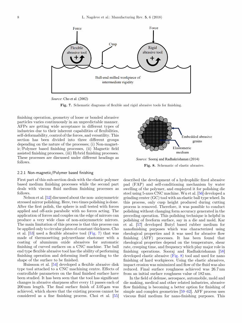
Fig. 7. Schematic diagrams of flexible and rigid abrasive tools for finishing.
8 L. Nagdeve et al.: Manufacturing Rev. 5, 6 (2018)
finishing operation, geometry of loose or bonded abrasiveparticles varies continuously in an unpredictable manner.AFPs are getting wide acceptance in different types ofindustries due to their inherent capabilities of flexibilities,self-deformability, control of the forces, and versatility. Thissection has been divided into three different groupsdepending on the nature of the processes; (i) Non-magnet-ic/Polymer based finishing processes, (ii) Magnetic fieldassisted finishing processes, (iii) Hybrid finishing processes.These processes are discussed under different headings asfollows.
Fig. 8. Schematic of elastic abrasive.
2.2.1 Non-magnetic/Polymer based finishing
First part of this sub-section deals with the elastic polymerbased medium finishing processes while the second partdeals with viscous fluid medium finishing processes asfollows.
Nelson et al. [52] discussed about the non- axisymmetricstressedmirror polishing. Here, two times polishing is done.After the first polish, the sphere is null tested with forcesapplied and off-axis parabolic with no forces acting. Theapplication of forces and couples on the edge of mirrors canproduce a very wide class of non-axisymmetric mirrors.The main limitation of this process is that this process canbe applied only to circular plates of constant thickness. Choet al. [53] used a flexible abrasive tool (Fig. 7) that wasmade of thermosetting polyurethane elastomer with acoating of aluminum oxide abrasives for automaticfinishing of curved surfaces on a CNC machine. The ballend type flexible abrasive tool has the ability of performingfinishing operation and deforming itself according to theshape of the surface to be finished.
Huissoon et al. [54] developed a flexible abrasive disktype tool attached to a CNC machining centre. Effects ofcontrollable parameters on the final finished surface havebeen studied. It has been seen that the tool has significantchanges in abrasive sharpness after every 11 passes each of200mm length. The final surface finish of 3.05mm wasachieved, which shows that the existing process cannot beconsidered as a fine finishing process. Choi et al. [55]
described the development of a hydrophilic fixed abrasivepad (FAP) and self-conditioning mechanism by waterswelling of the polymer, and employed it for polishing diesteel using 5-axes CNCmachine. Wu et al. [56] developed agrinding center (GC) tool with an elastic ball type wheel. Inthis process, only cusp height produced during cuttingprocess is removed. Therefore, it was possible to conductpolishing without changing form accuracy generated in thepreceding operation. This polishing technique is helpful inpolishing of freeform surface, say in a die and mold. Karet al. [57] developed Butyl based rubber medium fornanofinishing purposes which was characterized usingrheological properties and it was used for abrasive flowfinishing (AFF) processes. It has been found thatrheological properties depend on the temperature, shearrate, creeping time, and frequency which play major role infinishing operations. Sooraj and Radhakrishanan [58]developed elastic abrasive (Fig. 8) tool and used for nanofinishing of hard workpieces. Using the elastic abrasives,impact erosion was minimized and flow of the fluid was alsoreduced. Final surface roughness achieved was 26.7 nmfrom an initial surface roughness value of 182 nm.
In the field of defense, aerospace, automobile, mold anddie making, medical and other related industries, abrasiveflow finishing is becoming a better option for finishing ofsimple and complex geometries [59–62]. AFF process usesviscous fluid medium for nano-finishing purposes. This
Fig. 9. Schematic of abrasive particle held by polymer chainsand plasticizer.
L. Nagdeve et al.: Manufacturing Rev. 5, 6 (2018) 9
process also has been used for deburring, sharp edgerounding, removing recast layer and creating compressiveresidual stresses [63]. Tzeng et al. [64] discussed self-modulating abrasive medium and its applications inabrasive flow machining (AFM) process. Medium withcoarse abrasive particles and higher abrasive concentrationyields higher viscosity and improves surface finish. Asfinishing period increases, viscosity of the medium changes.It also revealed that the fluidity and stickiness nature of theself-modulating abrasive medium could be automaticallyadjusted, and used to finish tiny micro channels. Wanget al. [65] carried out experiments and removed recast layerof a complex hole by AFM process. Jain et al. [66] appliedFinite Element Method (FEM) to study AFF of complexgeometry. Theoretical models were developed for materialremoval and surface finish, and the theoretical results werecompared with the experimental results. It was concludedthat material removal is significantly affected by theextrusion pressure. It was also concluded that change in Ravalue of conical surface was less as compared to acylindrical surface while keeping the same extrusionpressure and no. of finishing cycles. Shankar et al. [67]developed different types of medium by homogeneouslymixing soft styrene butadiene based polymer, plasticizerand abrasive particles for finishing complex shapedcomponents (Fig. 9). The developed medium had theability of better flow ability, self-deformability, andabrading ability. Rheological properties of the AFFmedium are studied for evaluating finishing forces in thisresearch work [68,69]. Theoretical model was developedwhose results were in good agreement with the experimen-tal results. Cheema et al. [70] presented the state of the artof the experimental investigations on simple and compli-cated geometries using AFF process. It has been concludedthat the process is capable to produce nanometer levelsurface finish on intricate profiles including both internaland external surfaces. It has also been reported that thedevelopment of an appropriate medium for the givenapplication is the key parameter in the success of the AFFprocess. Sarkar and Jain [71] developed a flexible tool whichwas analogous to the ball end mill by curing polydieme-thylsiloxane (PDMS). Flexible tool follows the path on thecurved surface. A bowl shaped copper workpiece wasfinished. Final surface finish obtained was 53 nm from theinitial roughness of 241 nm. Different sizes of abrasiveparticles were used to improve surface roughness value ofthe workpiece. Sarkar and Jain [72] also applied AFFprocess for finishing of femoral component which hadcomplex geometry using AFF set up. Surface roughnessachieved varied from 42.9 nm to 62.5 nm in various areas onthe surface of the femoral component. Medium propertieschange with time during finishing process which is the mainlimitation of the process.
2.2.2 Magnetic field assisted finishing2.2.2.1 Magnetorheological finishing (MRF)
In these finishing processes, magnetic field is used toexternally control the forces acting on the workpiecethrough the abrasive particles. Magnetic field assistedfinishing processes have been established for a wide variety
of applications including dies and molds, medical compo-nents, fluid systems, optics, electronic components, microelectromechanical systems (MEMS), etc. In these finishingprocesses, magnetorheological (MR) polishing fluid is usedwhich changes its properties under the influence ofmagnetic field. The MR polishing fluid consists offerromagnetic particles, non-magnetic abrasive particles,carrier medium, and some additives. When this fluid comesin the magnetic field zone, multiple flexible brushes (selfadaptable/deforming brushes) are formed. These brushesare used for finishing freeform surfaces. Jacobs et al. [73,74]developed a magnetic field assisted method for producingcomplex optics with figure accuracy less than 50 nm andsurface roughness less than 1 nm. On the setup designedand fabricated (Fig. 10), the experiments were conductedusing different MR fluids and different materials. Kordon-ski et al. [75] developed the first versatile vertical wheelMRF prototype machine. They were successful inconducting the experiments on flat, concave and convexparts up to 100mm in diameter.
Cheng et al. [76] conducted experiments on reactionbonded silicon carbide (RB-SiC) using MRF, and goodsurface finish and figure accuracy were obtained. Twodifferent non-magnetic abrasive particles used were Al2O3and diamond with MR fluid. Diamond powder gave betterresults but it was more expensive. Cheng et al. [77]proposed MR fluid based finishing process using 2-axeswheel shaped polishing tool for aspheric parts. Two ringmagnets of high strength are kept on both side ends ofwheel tool and another two rectangular bar magnets arelocated near to the tool cover. Localized magnetic field ofhigh intensity is generated by this arrangement. It has beenfound that surface roughness of 1.2 nm is obtained from theinitial surface roughness of 3.8 nm, after 10min. But, thisprocess is more time consuming for complex surfacesbecause of only two axes rotation of tool. Seok et al. [78]used MRF process for generating curved surface on siliconbased microstructure. The profile of the finished surface issimulated by the FEM where the profile is generated byusing a concave tool holder in which MR fluid makesmultiple flexible brushes. Here, “edge effect” is obtainedbecause of very high magnetic field intensity at the edges.The results could have been better if non-magnetic
Fig. 10. Schematic diagram of MRF Process.
Fig. 11. Schematic diagram of the MR jet finishing process.
10 L. Nagdeve et al.: Manufacturing Rev. 5, 6 (2018)
abrasive particles had been used in the MR fluid. Tricardet al. [79,80] developed a new technique for finishingconcave and freeform surfaces using a round MR fluid jet.MR fluid jet becomes highly collimated, coherent and longstable in the presence of magnetic field (Fig. 11). This typeof arrangement is required for steep concave workpiece.The workpiece is kept at the top of the jet and it is
continuously rotated. This technique can be used to finishconcave surface of glass, single crystal silicon wafer andother complicated profiles, including the inaccessible areas.But, the main drawback of this technique is that the initialsurface roughness should be 300 nm or more and theworkpiece should be hard.
MRF was developed and commercialized by QEDcenter for optics manufacturing in Rochester, USA [81].MRF process uses magneto rheological fluid as a polishingtool to perform polishing operation with sub-nanometersurface roughness value. MRP fluid forms a flexiblepolishing tool which can polish different kinds of shapeswith an appropriate combination of MRP fluid andfinishing parameters. It is a deterministic process thathas the ability to finish spherical and plane surface with anoptimum value of accuracy of 30 nm peak to valley andsurface roughness of less than 1 nm for optical glasses,single crystals and glass ceramic.
Sidpara and Jain [82] developed a magneto-rheologicalfluid based nano finishing tool for femoral (Knee joints),which has a complex profile. Permanent magnet of highstrength was used to produce strong magnetic field in thefinishing zone. The finishing tool was held in the tool headof 3-axes CNCmillingmachine. In the presence of magneticfield, MR fluid gets stiffened and forms a hemisphericalshaped flexible brush. Different types of MR fluids (i.e. oil,water or chemical based) were prepared as a medium tofinish Titanium alloy knee joint implant. It was concludedthat water based MR fluid is more effective for finishing
Fig. 12. (a) Schematic diagram of MRF set-up for teeth finishing, (b) Photographic view of MRF set-up and (c) Photograph ofpartially finished tooth.
L. Nagdeve et al.: Manufacturing Rev. 5, 6 (2018) 11
hard materials. Final Ra value of 28 nm was achieved fromthe initial Ra value of 268 nm in 16.4 h of finishing of oneface of the knee implant. But, this process is more timeconsuming and produces non-uniform surface finish on fourdifferent faces of the femoral. In the same way, Baghel et al.[83] polished the artificial crown for a tooth, which is one ofthe examples of freeform surfaces usingmagnetorheologicalfluid based finishing process. They used 3-axes CNCmillingmachine for this purpose. Final surface roughness Ra valueachieved was 30 nm and 57 nm from the initial surfaceroughness 2790 nm in X direction and 3180 nm in the Ydirection, respectively (Fig. 12). It was found that arearoughness value was 1.43mm which got reduced to finalsurface roughness value of approximately 0.008mm. Theprofile of the crown was convex and the brush was not ableto reach uniformly on the whole surface of the crown.Further, the distance between the brush and upper surfaceof the crown was not constant (that is machining gap) andhence, the surface was not uniformly finished. InFigure 12c, the polished area can be clearly seen.
Jang et al. [84] developed a new kind of deburringprocess using MR fluid. They deburred the micro moldsand other micro features of complex shape of micro parts.The process was able to remove burrs having height of200mm and thickness of 1mm. Singh et al. [85,86]developed a setup for nanofinishing of 3-D surface usingthe ball end MR finishing tool. A ball end shape of MRpolishing fluid was produced at the top surface of therotating tool. In this setup, magnetic field is created byelectromagnets and MR fluid is supplied through thecentral rotating core. It is observed that in case of non-magnetic materials, the magnetic lines of force do not passthrough the workpiece andmajority of themagnetic lines offorce are diverted from inner core to outer core at the tip ofthe tool, and MR fluid becomes stiffened along thesemagnetic lines of force. It is concluded that the presentprocess is more suitable to finish non-magnetic materials.Ball end magnetorheological finishing (BEMRF) tool hasbeen also developed to finish mild steel work-piece surfaceby using both synthesized and unbounded magneticabrasive based polishing MR fluid [87]. The percentage
change in surface roughness (%DRa) was calculated in boththe cases. It was found that %DRa with bonded magneticabrasive particles was higher than unbounded magneticabrasive based MR fluid. The performance of the ball endMR finishing process was satisfactorily demonstrated onthe typical 3D ferromagnetic milled workpiece [88]. Thesurface roughness produced was as low as 16.6 nm, 30.4 nm,71 nm and 123.7 nm on flat, 30°, 45° and curved surfaces ofthe 3-D workpiece, respectively. The variation in themagnetic normal force can be minimized by providing atilting motion to the MR finishing tool so that a normal tothe tool tip surface can always be made perpendicular tothe 3-D workpiece surface being finished during finishingoperation. This will produce uniform magnetic normalforce and flux density zone irrespective of 3-D workpiecesurface. This would lead to a better surface finish even incase of curved surfaces. Suzuki et al. [89] developed amethod for curved shape workpiece (single-crystalLiNbL3) using magnetic field assisted finishing method.It is reported that when colloidal silica is used as non-magnetic abrasive particles, surface roughness of less than10 nm Rmax can be achieved.
Bedi and Singh [90] reported the state-of-the-art onmagnetorheological methods for nanofinishing. In thisarticles various MR fluid based finishing processes havebeen reported which full fill the demand of ultrafinesurfaces. It has also been suggested that use of computercontrolled nanofinishing method could be a better optionfor controlled magnetic field finishing for new engineeringmaterials including different sizes and shapes. Selection ofdifferent abrasive particles, particles sizes and particlesshapes can be more notable research area which wouldinfluence the finishing of new engineering materials.
Kim et al. [91,92] developed a new kind of deburringprocess using MR fluid for micro features of complex shapeof micro parts in general and formicromoulds in particular.The process was able to shear off the burrs of height up to200mm and thickness of 1mm in two stages. First, theabrasive tool was used and then flexible magnetic abrasivebrush (FMAB) was used for deburring and polishing offreeform surfaces, and three dimensional dies and moulds.
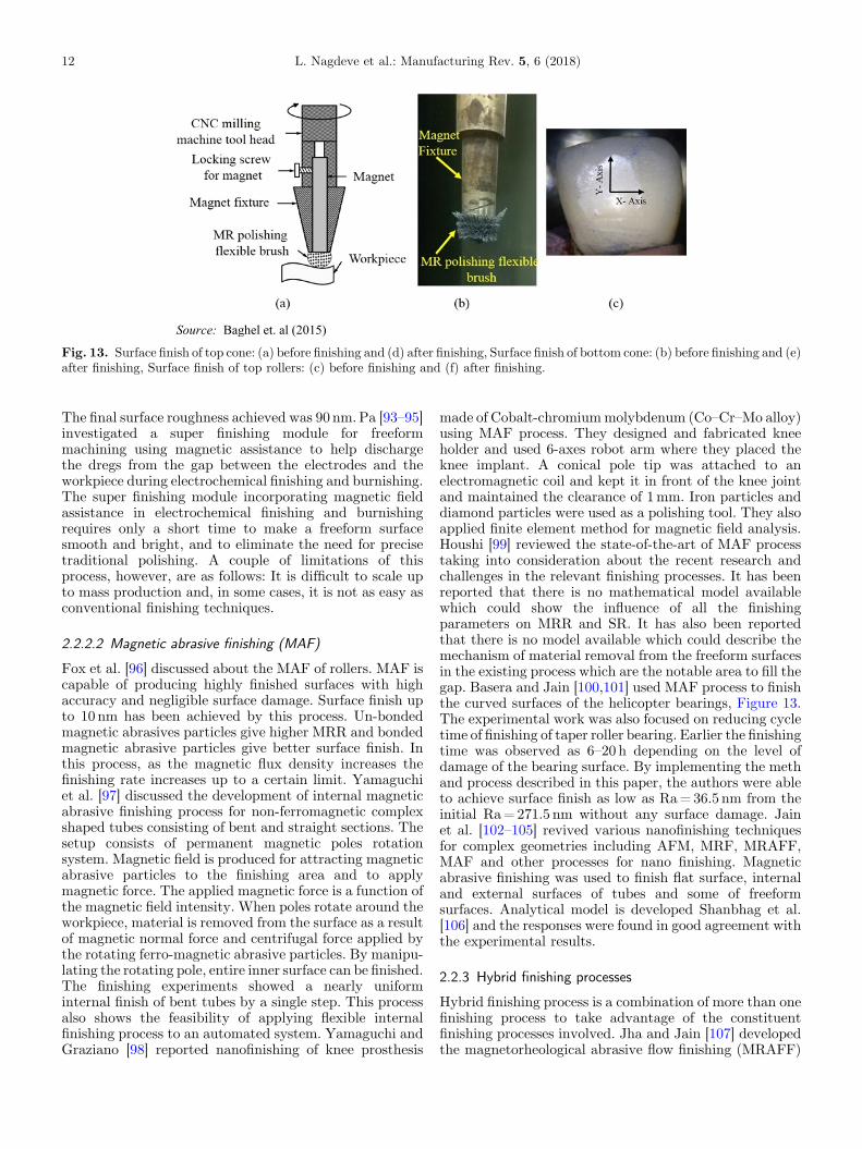
Fig. 13. Surface finish of top cone: (a) before finishing and (d) after finishing, Surface finish of bottom cone: (b) before finishing and (e)after finishing, Surface finish of top rollers: (c) before finishing and (f) after finishing.
12 L. Nagdeve et al.: Manufacturing Rev. 5, 6 (2018)
The final surface roughness achieved was 90 nm.Pa [93–95]investigated a super finishing module for freeformmachining using magnetic assistance to help dischargethe dregs from the gap between the electrodes and theworkpiece during electrochemical finishing and burnishing.The super finishing module incorporating magnetic fieldassistance in electrochemical finishing and burnishingrequires only a short time to make a freeform surfacesmooth and bright, and to eliminate the need for precisetraditional polishing. A couple of limitations of thisprocess, however, are as follows: It is difficult to scale upto mass production and, in some cases, it is not as easy asconventional finishing techniques.
2.2.2.2 Magnetic abrasive finishing (MAF)
Fox et al. [96] discussed about the MAF of rollers. MAF iscapable of producing highly finished surfaces with highaccuracy and negligible surface damage. Surface finish upto 10 nm has been achieved by this process. Un-bondedmagnetic abrasives particles give higher MRR and bondedmagnetic abrasive particles give better surface finish. Inthis process, as the magnetic flux density increases thefinishing rate increases up to a certain limit. Yamaguchiet al. [97] discussed the development of internal magneticabrasive finishing process for non-ferromagnetic complexshaped tubes consisting of bent and straight sections. Thesetup consists of permanent magnetic poles rotationsystem. Magnetic field is produced for attracting magneticabrasive particles to the finishing area and to applymagnetic force. The applied magnetic force is a function ofthe magnetic field intensity. When poles rotate around theworkpiece, material is removed from the surface as a resultof magnetic normal force and centrifugal force applied bythe rotating ferro-magnetic abrasive particles. By manipu-lating the rotating pole, entire inner surface can be finished.The finishing experiments showed a nearly uniforminternal finish of bent tubes by a single step. This processalso shows the feasibility of applying flexible internalfinishing process to an automated system. Yamaguchi andGraziano [98] reported nanofinishing of knee prosthesis
made of Cobalt-chromiummolybdenum (Co–Cr–Mo alloy)using MAF process. They designed and fabricated kneeholder and used 6-axes robot arm where they placed theknee implant. A conical pole tip was attached to anelectromagnetic coil and kept it in front of the knee jointand maintained the clearance of 1mm. Iron particles anddiamond particles were used as a polishing tool. They alsoapplied finite element method for magnetic field analysis.Houshi [99] reviewed the state-of-the-art of MAF processtaking into consideration about the recent research andchallenges in the relevant finishing processes. It has beenreported that there is no mathematical model availablewhich could show the influence of all the finishingparameters on MRR and SR. It has also been reportedthat there is no model available which could describe themechanism of material removal from the freeform surfacesin the existing process which are the notable area to fill thegap. Basera and Jain [100,101] used MAF process to finishthe curved surfaces of the helicopter bearings, Figure 13.The experimental work was also focused on reducing cycletime of finishing of taper roller bearing. Earlier the finishingtime was observed as 6–20 h depending on the level ofdamage of the bearing surface. By implementing the methand process described in this paper, the authors were ableto achieve surface finish as low as Ra=36.5 nm from theinitial Ra=271.5 nm without any surface damage. Jainet al. [102–105] revived various nanofinishing techniquesfor complex geometries including AFM, MRF, MRAFF,MAF and other processes for nano finishing. Magneticabrasive finishing was used to finish flat surface, internaland external surfaces of tubes and some of freeformsurfaces. Analytical model is developed Shanbhag et al.[106] and the responses were found in good agreement withthe experimental results.
2.2.3 Hybrid finishing processes
Hybrid finishing process is a combination of more than onefinishing process to take advantage of the constituentfinishing processes involved. Jha and Jain [107] developedthe magnetorheological abrasive flow finishing (MRAFF)
Fig. 14. (a) Schematic diagram of MRAFF process, and (b) Mechanism of material removal in MRAFF process.
L. Nagdeve et al.: Manufacturing Rev. 5, 6 (2018) 13
process by combining AFF and MRF processes. TheMRAFF setup is shown in Figure 14a and the mechanismof material removal in MRAFF process is shown inFigure 14b. AFF is not a deterministic process but MRF isa deterministic process where some of the processparameters can be externally changed, say, by changingthe current to the electromagnet, the magnetic field can bechanged during the process.
Das et al. [108,109] designed and developed the R-MRAFF setup and carried out experiments on the stainlesssteel tubes and flat surfaces. The medium has been rotatedby rotating the magnetic fixture in the existing MRAFFsetup. Therefore, rotation of the medium is attained in theexisting setup by rotation of the magnetic field, and hence,the process is known as rotating MRAFF (R-MRAFF)process. Kumar et al. [110] developed a fixture for femoralcomponent (Fig. 15) which is one of the examples offreeform surfaces and carried out the experiments on it.Magnetic fixture having 8 magnets was used in the setup.Mesh size and extrusion pressure were selected as variableparameters to study their effects on the final outcome. Ithas been observed that the process was useful for anycomplicated profile, but separate tooling is needed for eachworkpiece. It has also been noted that surface roughnesswas not uniform. They concluded that there is a need ofaugmentation in the workpiece fixture for getting uniformsurface finish by the existing set-up.
Hybrid finishing process is developed by combiningelastic emission machining (EEM) and MRF process toachieve atomic level of surface finish. In this finishingprocess, highMMR is achieved. In this hybrid process, timeand errors (placement, alignment, handling, etc.) can beminimized up to a great extent. Sidpara et al. [111] studiedthe fabrication and finishing processes (MRF and EMM) ofmirrors such as flat, cylindrical, elliptical and toroidalfollowed by various steps as grinding, etching, lapping, andpolishing. These processes are able to achieve surfaceroughness of a few Angstrom (below 1 nm) which isrequired in Synchrotron beam line for good focusingproperties and good reflectivity of X-rays. However, thereare few challenging issues related to the metrology becausethe measurement of surface roughness and slope errorsrequire specialized instruments on the specified level ofmeasurement.
Electrochemical honing is a hybrid super finishingprocess that associates advantages of both the processesthat is electrochemical machining and mechanical honing.Jain et al. [112] reported the state-of-the- art of ECH inwhich more than 90% of material is removed by electrolyticaction and remaining 10% is removed by abrasive honingaction. Pathak et al. [113] reported the mechanism of gearfinishing by pulse electrochemical honing (PECH). Moreresearch areas can be found to finish and explore the ECHprocess in herringbone, hypoid, worm and worm gear.
Fig. 15. Schematic of R-MRAFF process.
Table 1. Comparisons of abrasive-based finishing processes, Jain and Jain [110].
S. No Finishing process Work-piece Ra (nm)
1 Grinding – 25–62502 Honing – 25–15003 Lapping – 13–7504 Abrasive flow machining (AFM) with SiC abrasives Hardened steel 505 Magnetic abrasive finishing (MAF) with diamond abrasives Stainless steel rods 7.66 Magnetic float polishing (MFP) with CeO2 abrasives Si3N4 4.07 Magnetorheological finishing (MRF) with CeO2 Flat BK7 glass 0.88 Elastic emission machining (EEM) with ZrO2 abrasives Silicon <0.59 Ion beam machining (IBM) Cemented carbide 0.1
14 L. Nagdeve et al.: Manufacturing Rev. 5, 6 (2018)
Efforts are being made to develop new finishingprocesses in order to incorporate the merits of theindividual processes into the new processes. In this way,Jain et al. [114] developed the chemo-mechanical magneto-rheological finishing (CMMRAFF) process as a superfinishing process by combining three different finishingprocesses namely, chemo mechanical polishing, MRF andabrasive flow finishing processes. Minimum surfaceroughness of 0.486 nm was achieved on a single crystalsilicon wafer surface. The main characteristic ofCMMRAFF process is that this process can be employedfor all engineering material by optimizing chemicalcomposition of MRP fluid. Table 1 and Table 2 showsthe overall comparison of all the traditional and advancedfinishing processes with different characteristics employedfor finishing of freeform surfaces.
3 Issues to be addressed in nano-finishing offreeform surfaces
3.1 Existing challenges
The following areas are identified to be ones that wouldneed attention for further research:
– design and development of a fixture as the extendedreplica of the component with freeform surface andonline monitoring of input process parameters, namely,magnetic field, medium flow velocity or mediumpressure, etc;
–
3-D CFD simulation of MR polishing fluid, comprehen-sive modeling by coupling different physical phenomenato estimate velocities and forces in the fluid flowchannel;
Tab
le2.
Com
parisonof
differentad
vanced
nano
-finishingtechniqu
esused
forfreeform
surfaces.
Cha
racteristics
AFM
MAF
MRFF
MRAFF
R-M
RAFF
Adv
ancedR-M
RAFF
Basemedium
and
abrasive
Polym
eras
aviscoelastic
base
medium
mixed
with
fine
abrasives
non-mag
netic
abrasive
particles
andferrom
agnetic
particlesan
dad
ditives
Water
basedor
Oil
basedmedium
mixed
withcerium
oxideab
rasives
Mineral
oilan
dgrease
asviscop
lastic
medium
withCIP
san
ddifferenttypesof
abrasivesdepend
ing
upon
requ
irem
ent
Sameas
inMRAFF
Sameas
inMRAFF
Workp
iece
fixture
Cylindrical
Flat,ho
ldingdevices
depend
ingon
workp
iece
Workp
iece
isfixed
byan
device
and
pend
ulum
motionis
givento
workp
iece
Cylindrical
Cylindrical
Negativereplicaof
workp
iece
Working
principle
Toan
dfroflow
ofab
rasive
laden
viscoelastic
medium
throug
htherestricted
passag
e
Relativemotionof
medium
(FMAB)
withworkp
iece
Toan
dpro
mag
netically
stiffened
MR
polishing
fluidin
the
vicinity
ofworkp
iece
surface
Toan
dfroextrusion
ofmag
netically
stiffened
MR
polishing
fluidov
erworkp
iece
surface
Rotationas
wellas
toan
dfroextrusionof
mag
netically
stiffened
MR
polishing
fluidov
erworkp
iece
surface
Rotationas
wellas
toan
dfroextrusionof
mag
netically
stiffened
MR
polishing
fluidov
erworkp
iece
surface
throug
hun
iform
chan
nel
Mecha
nism
ofmaterialremov
alIndentation&
shearing
ofmaterial
intheform
ofmicrochips
Indentationan
dremov
alof
material
dueto
rotation
ofbrush
Shearing
and
materialremov
alin
theform
ofmicrochips
Shearing
and
materialremov
alin
theform
ofmicrochips
Shearing
andmaterial
remov
alin
theform
ofmicrochips
Shearing
andmaterial
remov
alin
theform
ofmicrochips
Minim
umsurface
roug
hness
46.6nm
Saraka
ran
dJa
in[Sarka
ran
dJa
in]36
.5nm
[Baseraan
dJa
in]
28nm
[Sidpa
raan
dJa
in]
36nm
[Kum
aran
dJa
in]
26nm
[Nag
deve
etal.]
App
lications
Smallho
lesin
micro-
rang
e,internal,an
dexternal
3Dcomplex
shap
edsurfaces
Flat,cylin
drical,
helical
geom
etry,
internal
and
external
surfaces
ofcylin
drical
geom
etry
Flat,spherical,
concav
e,conv
exan
dasph
erical
external
surfaces.Brittle
compo
nent
etc.
Non
-mag
netic
internal
closed
surfaces
and
external
surfaces
irrespective
ofmaterialtype
Internal
andexternal
surfaceof
anycomplex
geom
etricalshap
esof
non-mag
neticmaterial
irrespective
ofha
rdness
Internal
andexternal
surfaceof
anycomplex
geom
etricalshap
esof
non-mag
neticmaterial
irrespective
ofha
rdness
Lim
itations
Not
determ
inistic
Deterministic
Deterministic
Deterministic
Deterministic
Deterministic
Cha
lleng
esTocontrolthe
medium
prop
erties
during
experiments
Finishing
ofcomplex
features
inminim
umtime
Reducingfinishing
time
3-D
CFD
simulation
ofMR
polishing
fluid
Use
ofMag
neticreplica
offreeform
surfaceto
generate
theun
iform
mag
neticfixture
Use
ofMag
neticreplica
offreeform
surfaceto
generate
theun
iform
mag
neticfixture
Finishing
ofcomplex
features
Reducingfinishing
time
3-D
CFD
simulationof
MR
polishing
fluid
3-D
CFD
simulationof
MR
polishing
fluid
Toarchiveun
iform
surfacefinish
Reducingfinishingtime
Reducingfinishingtime
Toarchiveun
iform
surfacefinish
Toachieveun
iform
surfacefinish
L. Nagdeve et al.: Manufacturing Rev. 5, 6 (2018) 15
Fig. 16. (a) Solid model of the Knee Joint, (b) Solid model of negative replica of a Knee Joint, (c) Photographic view of R-MRAFFsetup and (d) Fabricate and assembly of replica fixture where knee joint is kept.
16 L. Nagdeve et al.: Manufacturing Rev. 5, 6 (2018)
–
reducing finishing time and obtaining uniform surfacefinish. It requires improvement in MR polishing fluid anddesign of a fixture for the workpiece;
–
on-line control of fluid properties in the presence ofmagnetic field is required to control the forces acting onthe workpiece surface.
For achieving uniform desired surface roughness on theworkpiece, proper arrangement of the poles of the magnetsis required so that the uniform magnetic field could beachieved at the outer surface of the workpiece to be finished.In this direction, Nagdeve et al. [115] designed anddeveloped the negative replica or cavity of the freeformsurface (knee joint) for uniformdistribution ofMRpolishingfluid and to generate uniform pulsatingmagnetic field in thefinishing region. Figure 16b shows a proposed workpiecefixture design for R-MRAFF process. The objective of thisdesign was to produce a constant velocity of MR fluid in thefinishing region and to reduce the total finishing time.
Figure 16a shows the solid model of a knee joint which isplaced inside the replica (see Fig. 16d). Figure 16c shows thephotographic view of R-MRAFF setup. Minimum surfaceroughness of 26 nm was achieved using this system.
3.2 Future scope3.2.1 Experimental work
The following are some exploratory areas in which furtherexperimental research would be needed to enhance theperformance of the finishing processes:
– for providing uniform magnetic field in different areas ofthe freeform surfaces, the negative replica can be used asa magnet fixture keeping in view that the radial distancebetween the freeform surface to be finished and themagnet surface is maintained almost constant. It will beable to produce almost constant magnetic field indifferent areas where finishing is to be done;
L. Nagdeve et al.: Manufacturing Rev. 5, 6 (2018) 17
–
the arrangement of magnets in the fixture can be madesuch that it produces pulsating magnetic field of thedesired frequency and strength along the freeformsurfaces;
–
rheological study of the MR fluid can be done for gettingappropriate yield stress and viscosity which play a majorrole in the finishing of freeform surfaces;
–
experiments can be conducted by maintaining differentgaps between the workpiece surface and replica offreeform surfaces and then analyzing the results foroptimizing the gap.
3.2.2 Theoretical work
–
2D-CFD simulation would be needed to analyze the exactvelocity profile along the curvature of all the surfaces ofthe freeform surfaces.
–
Numerical analysis and correlation among materialremoval and surface finish should be conducted.
–
A mathematical model of physical phenomenon ofmaterial removal and forces involved during the finishingprocess should be developed.
–
Parametric analysis of the employed processes whilecreating a freeform surface should be performed. Also, apredictive surface finish model should be developed.
–
Molecular dynamics simulations of CIPs and abrasiveparticle chains should be conducted to model the actualforces applied by abrasive particles on the surfaces to befinished.
4 Conclusion
Several configurations of conventional and non-conven-tional finishing processes such as grinding, buffing, honing,ball burnishing, soft and elastic abrasive tool and MR fluidbased finishing processes have been presented for finishingof freeform/sculptured surfaces. It is a challenging task toobtain a uniform surface finish in case of freeform surfaces.The review conducted leads to the following conclusions:
– 5 or 7 axes CNC machines are capable to produce evensurface finish, but in case of freeform surfaces in thenanometer range, it is still not satisfactory;
–
due to complex geometry, finishing time required is veryhigh. Although, drag finishing and belt finishing havebeen extensively used in the industries, but they are notable to produce the uniform surface finish;
–
finishing of freeform surfaces using abrasive flow finishingprocess is possible but external control of the forcesacting on the freeform surfaces is not feasible;
–
finishing of freeform surfaces is feasible through deploy-ing a flexible magnetic abrasive brush concept, involvingmagnetic field assisted nanometer finishing processessuch as MAF, MRF and MRAFF;
–
for achieving uniform surface finish in the case offreeform surfaces using a magnetorheological-fluid basedfinishing process, negative replica seems to be a potentialsolution.
References
1. L. Nagdeve, V.K. Jain, J. Ramkumar, Differential finishingof freeform surfaces (Knee joint) using R-MRAFF process &negative replica as a fixture, Mach. Sci. Technol. Int. J.(2017) 1–25 DOI: 10.1080/10910344.2017.1402929
2. L. Nagdeve, V.K. Jain, J. Ramkumar, Preliminary inves-tigations into nano-finishing of freeform surface (femoralcomponent) using inverse replica fixture, Int. J. Adv.Manuf.Technol. (2017) 1–12 DOI: 10.1007/s00170-017-1459-7
3. A. Lasemi, D. Xue, P.A. Gu, Freeform surface manufactur-ing approach by integration of inspection and tool pathgeneration, Int. J. Prod. Res. 50 (2012) 6709–6725
4. A. Lasemi, D. Xue, P.A. Gu, Recent development in CNCmachining of freeform surfaces: a state-of-the-art review,CAD Comput. Aided Des. 42 (2010) 641–654
8. ASTM standard: F 2083 -11 standard specifications for totalknee prosthesis, 1–9 DOI:10.1520/ F2083–11. 2
9. Z. Zhong, T. Nakagawa, New grinding methods for asphericmirrors with large curvature radii, CIRP Ann. Manuf.Technol. 41 (1992) 335–338
10. J. Zhao et al., A new method of automatic polishing oncurved aluminium alloy surfaces at constant pressure, Int. J.Mach. Tools Manuf. 35 (1994) 1683–1692
12. R. Balasubramaniam, R.V. Sarepaka, S. Subbiah,Micro andnano manufacturing series-diamond turn machining: theoryand practice, CRC Press, New York 2017, 160 p, ISBN&9781138748323 (Taylor & Francis Group)
13. Z. Pan, Y. Feng, S.Y. Liang, Material microstructureaffected machining: a review, Manufacturing Rev. 4 (2017)1–12
14. I. Hilerio, T.Mathia, C. Alepee, 3Dmeasurements of the kneeprosthesis surfaces applied in optimizing of manufacturingprocess, Wear 257 (2004) 1230–1234
15. H.Y. Tam, M. Hua, L. Zhang, Aspheric surface finishing byfixedabrasives, Int.J.Adv.Manuf.Technol.34(2007)483–490
16. I. Lazoglu, C. Manav, Y. Murtezaoglu, Tool path optimi-zation for free form surface machining, CIRP Ann. Manuf.Technol. 58 (2009) 101–104
17. B.J. Plichta, Grinding and finishing of sculptured surfacesusing an innovative multi tool head with independentpneumatic drive, J. Mach. Eng. 12 (2012) 7–14
18. N. Umehara, R. Komanduri, Magnetic fluid grinding of HIP-Si3N4 rollers, Wear 192 (1996) 85–93
19. T. Kuriyagawa, M.S.S. Zahmaty, K. Syoji, A new grindingmethod for aspheric ceramic mirrors, J. Mater. Process.Technol. 62 (1996) 387–392
20. B. Nowicki, M. Szafarczyk, The new method of free formsurface honing, Ann. CIPR 42 (1993) 425–428
21. R. Dynarowski, B. Nowicki, Investigation on non-conven-tional honing of sculptured surfaces for parts made of alloysteel, J. Mater. Process. Technol. 109 (2001) 270–276
27. Y. Song, C.H. Park, T. Moriwaki, Mirror finishing of Co-Cr-Mo alloy using elliptical vibration cutting, Precis. Eng. 34(2010) 784–789
28. R.H.M. Jafar, J.K. Spelt, M. Papini, Surface finishing ofmicro-channels using low kinetic energy abrasives, Int. J.Mech. Eng. Mechatron. 2 (2014) 43–50
29. H. Huang et al., Robotic grinding and polishing for turbine-vane overhaul, J.Mater. Process. Technol. 127 (2002) 140–145
30. H.Y. Tam, O.C.H. Lui, A.C.K. Mock, Robotic polishing offree-form surfaces using scanning paths, J. Mater. Process.Technol. 95 (1999) 191–200
31. H. Weule, D. Spath, U. Schauer, Robot assisted finishing ofdies and molds with automated quality control, Prod. Eng.112 (1994) 229–232
32. Y. Mizugaki et al., Development of metal-mold polishingrobot system with contact pressure control using CAD/CAM data, CIRP Ann. Manuf. Technol. 39 (1990) 523–526
33. H. Weule, S. Timmerman, Automation of the surfacefinishing in the manufacturing of dies andmolds, CIRPAnn.Manuf. Technol. 39 (1990) 299–303
34. G.B. Richard et al., Novel automated process for asphericsurface, Proc. SPIE 2000 Curr. Dev. Lens Des. Opt. Syst.Eng. 4093 (2000) 445–450
35. J. Zhao et al., Oblique ultrasonic polishing method by robotfor free-form surfaces, Int. J. Mach. Tools Manuf. 40 (2000)795–808
36. C. Brecher et al., Development of a force controlled orbitalpolishing head for free form surface finishing, Prod. Eng. 4(2010) 269–277
37. G. Elber, Freeform surface region optimization for 3-axisand 5-axis milling, Comput. Aided Des. 27 (1995) 465–470
38. J.S. Chen, Y.K. Huang, M.S. Chen, A study of the surfacescallop generating mechanism in the ball-end millingprocess, Int. J. Mach. Tools Manuf. 45 (2005) 1077–1084
39. C. Brecher et al., NURBS based ultra-precision free-formmachining, CIRP Ann. Manuf. Technol. 55 (2006) 547–550
40. R. Baptista, J.F.A. Simões, Three and five axes milling ofsculptured surfaces, J. Mater. Process. Technol. 103 (2000)398–403
41. J.H. Ahn et al., Intelligently automated polishing for highquality surface formation of sculptured die, J. Mater.Process. Technol. 130 (2002) 339–344
42. J.H. Ahn et al., Development of a sensor informationintegrated expert system for optimizing die polishing,Robot. Comput. Integr. Manuf. 17 (2001) 269–276
43. A. Walker et al., New results from the Precessions polishingprocess scaled to larger sizes, Proc. SPIE 5494 (2004) 71–80DOI: 10.1117/12.553044
44. A. Walker et al., The Precessions tooling for polishing andfiguring flat, spherical and aspheric surfaces, Opt. Express 11(2003) 958–964
45. L. Blunt et al., The application of optics polishing to freeform knee implants, in: Proceedings of the 6th EuspenInternational Conference-Baden bei, Wien, 2006, pp. 1–4
46. P. Charlton, L. Blunt, Surface and formmetrology of polishedfreeform biological surfaces, Wear 264 (2008) 394–399
47. C.F. Cheung et al., Analysis of surface generation in theultraprecision polishing of freeform surfaces, Proc. Inst.Mech. Eng. Part B: J. Eng. Manuf. 224 (2010) 59–73
48. A. Denkena, J. Köhler, M.V.D. Vander, A roughness modelfor the machining of biomedical ceramics by toric grindingpins, CIRP J. Manuf. Sci. Technol. 6 (2013) 22–33
49. A. Turger et al., Manufacturing conditioned roughness andwear of biomedical oxide ceramics for all-ceramic kneeimplants, Biomed. Eng. Online 12 (2013) 1–17
50. A. Curodeau, E. Sachs, S. Caldarise, Design and fabricationof cast orthopedic implants with freeform surface texturesfrom 3-D printed ceramic shell, J. Biomed. Mater. Res. 53(2000) 525–535
51. E.P. Koumoulos, E. Gkartzou, C.A. Charitidis, Additive(nano) manufacturing perspectives: the use of nanofillersand tailored materials, Manufacturing Rev. 4 (2017) 12
52. J. Nelson, Non-axisymmetric mirrors produced by stressedmirror polishing, Precis. Eng. 3 (1981) 7–10
54. J.P. Huissoon et al., Automated polishing of die steelsurfaces, Int. J. Adv. Manuf. Technol. 19 (2002) 285–290
55. J.Y. Choi, H.D. Jeong, A study on polishing of molds usinghydrophilic fixed abrasive pad, Int. J. Mach. Tools Manuf.44 (2004) 1163–1169
56. X. Wu, Y. Kita, K. Ikoku, New polishing technology of freeform surface by grinding center, J. Mater. Process. Technol.187 (2007) 81–84
57. K.K. Kar et al., Performance evaluation and rheologicalcharacterization of newly developed butyl rubber basedmedia for abrasive flow machining process, J. Mater.Process. Technol. 209 (2009) 2212–2221
58. V.S. Sooraj, V. Radhakrishnan, Fine finishing of internalsurfaces using elastic abrasives, Int. J. Adv.Manuf. Technol.73 (2014) 1495–1509
59. K. Przyklenk, Abrasive flow machining—a process forsurface finishing and deburring of workpieces with acomplicated shape by means of abrasive laden media, AdvNontradit. Mach. PED ASME 22 (1986) 101–110
61. L. Rhoades, Abrasive flowmachining: a case study, J.Mater.Process. Technol. 28 (1991) 107–116
62. T.R. Loveless, R.E. Williams, K.P. Rajurkar, A study of theeffects of abrasive-flow finishing on various machinedsurfaces, J. Mater. Process. Technol. 47 (1994) 133–151
64. H.J. Tzeng et al., Self-modulating abrasive medium and itsapplication to abrasive flow machining for finishing microchannel surfaces, Int. J. Adv. Manuf. Technol. 32 (2007)1163–1169
L. Nagdeve et al.: Manufacturing Rev. 5, 6 (2018) 19
65. A.C. Wang et al., Uniform surface polished method ofcomplex holes in abrasive flow machining, Trans. NonferrousMetal. Soc. China (English Edition) 19 (2009) s250–s257
66. V.K. Jain et al., Investigations into abrasive flow finishingof complex workpieces using FEM, Wear 267 (2011) 71–80
67. M.R. Sarkar, V.K. Jain, J. Ramkumar, Rheologicalcharacterization of styrene-butadiene based medium andits finishing performance using rotational abrasive flowfinishing process, Int. J. Mach. Tools Manuf. 51 (2011) 947–957
68. J.K. Sambharia, H.S. Mali, Characterisation and perfor-mance evaluation of developed alternative polymer abrasivegels for abrasive flow finishing process, Int. J. Precis.Technol. 5 (2015) 185–200
69. S. Singh et al., Modelling of nano-finishing forces and surfaceroughness in abrasive flow finishing process using rheologicalproperties, Int. J. Precis. Technol. 6 (2016) 123–141
70. M.S. Cheema et al., Developments in abrasive flowmachining: a review on experimental investigations usingabrasive flow machining variants and media, Proc. Inst.Mech. Eng. Part B: J. Eng. Manuf. 226 (2012) 1951–1962
71. M. Sarkar, V.K. Jain, Development of a flexible abrasive toolfor nano finishing of complex surfaces, in: Development of aFlexible Abrasive Tool for Nano Finishing of ComplexSurfaces, Vision for Future (MVF2013) Conference atIndian Institute of Technology, Guwahati, India, 2013
72. M. Sarkar, V.K. Jain, Nanofinishing of freeform surfacesusing abrasive flow finishing process, Proc. Inst. Mech. Eng.Part B: J. Eng. Manuf. 231 (2017) 1501–1505
73. S.D. Jacobs, in: T. Kasai (Ed.), Optical Fabrication andTesting, SPIE, Bellingham, WA 1995, pp. 372–382
74. S.D. Jacobs, Magnetorheological finishing: a deterministicprocess for optics manufacturing, in: T. Kasai (Ed.),Proceedings of the International Conference on Opticalfabrication and testing, Tokyo, Japan, 1995, pp.
75. W.I. Kordonski, S.D. Jacobs, D. Golini, Technical digestseries, in: Optical fabrication and testing, Optical Society ofAmerica, Washington, DC, 1996, pp. 146–149
76. H. Cheng, Z. Feng, Y. Wang, Magnetorheological finishingof SiC aspheric mirrors, Mater. Manuf. Process. 20 (2005)917–931
77. H.B. Cheng, Y. Yam, Y.T. Wang, Experimentation on MRfluid using a 2-axis wheel tool, J. Mater. Process. Technol.209 (2009) 5254–5261
78. J. Seok, Y.J. Kim, K.I. Jang, A study on the fabrication ofcurved surfaces usingmagnetorheological fluid finishing, Int.J. Mach. Tools Manuf. 47 (2007) 2077–2090
79. M. Tricard, P.R. Dumas, D. Golini, SOI wafer polishingwith magnetorheological finishing (MRF), SOI Conf. 3/6(2003) 127–129
80. M. Tricard, W.I. Kordonski, A.B. Shorey, Magnetorheo-logical jet finishing of conformal, freeform and steep concaveoptics, CIRP Ann. Manuf. Technol. 55 (2006) 309–312
81. D.C. Harris, History of magnetorheological finishing,window and dome technologies and materials XII, Int.Soc. Opt. Photonics 8016 (2011) 80160N
82. A.M. Sidpara, V.K. Jain, Nanofinishing of freeform surfacesof prosthetic knee joint implant, Proc. Inst. Mech. Eng. PartB: J. Eng. Manuf. 226 (2012) 1833–1846
83. P. Baghel et al., Preliminary investigation into finishing ofartificialdentalcrown,Int.J.Precis.Technol.5(2015)229–245
84. K.I. Jang, D.Y. Kim, S. Maeng, Deburring microparts usinga magnetorheological fluid, Int. J. Mach. Tools Manuf. 53(2012) 170–175
85. A. Singh, S. Jha, P.M. Pandey, Design and development ofnanofinishing process for 3D surfaces using ball end MRfinishing tool, Int. J. Mach. Tools Manuf. 51 (2011) 142–151
86. A. Singh, S. Jha, P.M. Pandey, Nanofinishing of a typical 3Dferromagnetic workpiece using ball end magnetorheologicalfinishing process, Int. J.Mach. ToolsManuf. 63 (2012) 21–31
87. M.S. Niranjan, S. Jha, Optimum selection of machiningparameters in ball end magnetorheological finishing process,Int. J. Precis. Technol. 5 (2015) 217–228
88. A.K. Singh, S. Jha, P.M. Pandey, Performance evaluation ofimproved ball end magnetorheological finishing processes,World Academy of Science, Engineering and Technology,Int. J. Mech. Aerosp. Ind. Mechatron. Manuf. Eng. 6 (2012)356–360
89. H. Suzuki et al., Magnetic field-assisted polishing applica-tion to curved surface’ Precision Engineering 11 (1989) 197–202
90. T.S. Bedi, A.K. Singh, Magnetorheological methods fornanofinishing a review, Part. Sci. Technol. 34 (2016) 412–422
91. J.D. Kim, I.H. Noh, Magnetic polishing of three dimensionaldie and mold surfaces, Int. J. Adv. Manuf. Technol. 33(2007) 18–23
92. J.D. Kim, M.S. Choi, Study on magnetic polishing of free-form surfaces, Int. J. Mach. Tools Manuf. 37 (1997) 1179–1187
93. P.S. Pa, Design of a magnetic-assistance super finish modulefor freeform machining, J. Vac. Sci. Technol. B Micro-electron. Nanometer Struct. 27 (2009) 1221
94. P.S. Pa, Magnetic-assistance finishing processes in freeformsurfaces, J. Mater. Eng. Perform. 18 (2009) 99–405
95. P.S. Pa, Super finishing with ultrasonic and magneticassistance in electrochemical micro-machining, Electrochim.Acta 54 (2009) 6022–6027
96. M. Fox, K. Agrawal, T. Shinmura, Magnetic abrasivefinishing of rollers, CIRP Ann. Manuf. Technol. 43 (1994)181–184
97. H. Yamaguchi, T. Shinmura, A. Kobayashi, Development ofan internal magnetic abrasive finishing process for non-ferromagnetic complex shaped tubes, Jpn. Soc. Mech. Eng.44 (2001) 275–281
98. H. Yamaguchi, A. Graziano, Surface finishing of cobaltchromium alloy femoral knee components, CIRP Ann.Manuf. Technol. 63 (2014) 309–312
99. M.N. Houshi, A comprehensive review on magnetic abrasivefinishing process, Adv. Eng. Forum 18 (2016) 1–20
100. P.K. Basera, V.K. Jain, Nano-finishing of aircraft bladebearing by magnetic abrasive finishing (MAF) process, 2ndAnnual International Conference on Material Science,Metals and Manufacturing (M3 2012), 2012, pp. 129–136
101. P.K. Basera, V.K. Jain, Reducing downtime of repairing fortaper roller bearing by magnetic abrasive finishing (MAF)process, Int. J. Innov. Manag. Technol. 4 (2013) 130–136
102. V.K. Jain et al., Nano-finishing techniques: a review, Proc.Inst.Mech.Eng.PartC:J.Mech.Eng.Sci. 226 (2012)327–346
106. V.V. Shanbhag et al., Modelling for evaluation of surfaceroughness in magnetic abrasive finishing of flat surfaces, Int.J. Precis. Technol. 6 (2016) 159–170
107. S. Jha, V.K. Jain, Design and development of the magneto-rheological abrasive flow finishing (MRAFF) process, Int. J.Mach. Tools Manuf. 44 (2004) 1019–1029
109. M. Das, V.K. Jain, P.S. Ghoshdastidar, Nanofinishing of flatworkpieces using rotational-magnetorheological abrasiveflow finishing (R-MRAFF) process, Int. J. Adv. Manuf.Technol. 62 (2012) 405–420
110. S. Kumar, V.K. Jain, A. Sidpara, Nanofinishing of freeformsurfaces (knee joint implant) by rotational-magnetorheo-logical abrasive flow finishing (R-MRAFF) process, Precis.Eng. 42 (2015) 165–178
111. A. Sidpara, V.K. Jain, G.S. Lodha, Finishing of synchrotronbeamline mirrors, 5th International & 26th All IndiaManufacturingTechnology, Design andResearch Conference(AIMTDR 2014), IIT Guwahati, Assam, India, 2014, pp. 1–6
112. N.K. Jain et al., State of the art review of electrochemicalhoning of internal cylinders and gears, Proc. Inst. Mech.Eng. Part B: J. Eng. Manuf. 223 (2009) 665–681
113. S. Pathak, N.K. Jain, I.A. Palani, Effect of honing gearhardness on surface quality and micro-geometry improve-ment of straight bevel gear in PECH process, Int. J. Adv.Manuf. Technol. 85 (2016) 2197–2205
114. V.K. Jain et al., Chemo-mechanical magneto-rheologicalfinishing (CMMRF) of silicon for microelectronics applica-tions, CIRP Ann. Manuf. Technol. 59 (2010) 323–328
115. L. Nagdeve, V.K. Jain, J. Ramkumar, Experimentalinvestigations into nano-finishing of freeform surfaces usingnegative replica of the knee joint, Procedia CIRP 42 (2016)793–798
116. R.K. Jain, Modeling and simulation of abrasive flowmachining process, PhD thesis, Indian Institute of Technol-ogy, Kanpur, India, 1999
Cite this article as: Leeladhar Nagdeve, V.K. Jain, J. Ramkumar, Nanofinishing of freeform/sculptured surfaces: state-of-the-art,Manufacturing Rev. 5, 6 (2018)