American Institute of Aeronautics and Astronautics 1 NASA Puffin Electric Tailsitter VTOL Concept Mark D. Moore 1 NASA Langley Research Center, Hampton, VA 23681 Electric propulsion offers dramatic new vehicle mission capabilities, not possible with turbine or reciprocating engines; including high reliability and efficiency, low engine weight and maintenance, low cooling drag and volume required, very low noise and vibration, and zero emissions. The only penalizing characteristic of electric propulsion is the current energy storage technology level, which is set to triple over the next 5-10 years through huge new investments in this field. Most importantly, electric propulsion offers incredible new degrees of freedom in aircraft system integration to achieve unprecedented levels of aerodynamic, propulsive, control, and structural synergistic coupling. A unique characteristic of electric propulsion is that the technology is nearly scale-free, permitting small motors to be parallelized for fail-safe redundancy, or distributed across the airframe for tightly coupled interdisciplinary functionality without significant impacts in motor- controller efficiency or specific weight. Maximizing the potential benefit of electric propulsion is dependent on applying this technology to synergistic mission concepts. The vehicle missions with the most benefit include those which constrain environmental impact (or limit noise, exhaust, or emission signatures) are short range, or where large differences exist in the propulsion system sizing between takeoff and cruise conditions. Electric propulsion offers the following unique capabilities that other propulsion systems can’t provide for short range Vertical Takeoff and Landing (VTOL) aircraft; elimination of engine noise and emissions, drastic reduction in engine cooling and radiated heat, drastic reduction in vehicle vibration levels, drastic improvement in reliability and operating costs, variable speed output at full power, for improved cruise efficiency at low tip-speed, elimination of high/hot sizing penalty, and reduction of engine-out penalties. I. Introduction lectric propulsion is a potential game changing technology for aircraft. It offers as significant of a transformation as the change from internal combustion to turbine engines. Looking into the future, it has the potential to transform aircraft and create new aviation markets. While this paper focuses on a single advanced concept designed with a primary electric propulsion system for a specific mission intent, there is the potential for electric propulsion to impact many missions with very different integrations. Other advanced concepts, Figure 1, have also been developed for other missions, and while they will not be discussed in detail in this paper, also offer insight into the intriguing potential of electric propulsion as a powerful new technology that provides aircraft designers with the potential for highly synergistic integration. These other electric propulsion concepts are mentioned below to indicate the breadth of possibilities that electric propulsion offers, and the potential this technology has to result in very different functioning aircraft that can bring about entirely new mission capabilities. For this reason electric propulsion is considered a ‘frontier’ technology that offers an ability to achieve capabilities previously not possible. • Hyper efficient general aviation aircraft to achieve greater than 200 passenger miles per gallon at speeds greater than 100 mph. This particular concept utilizes a hybrid-electric propulsion system integrated with a boundary layer ingestion inlet to accomplish very high installed propulsion efficiency, and a cruise optimized engine installation that is augmented by electric wingtip propulsor/turbines for low speed takeoff and climb thrust with a much lower disc-loading propeller. 1 Aerospace Engineer, Aeronautics Systems Analysis Branch, NASA Langley, MS 442, AIAA Member. E https://ntrs.nasa.gov/search.jsp?R=20110011311 2018-05-21T09:01:58+00:00Z
Transcript
American Institute of Aeronautics and Astronautics
1
NASA Puffin Electric Tailsitter VTOL Concept
Mark D. Moore1
NASA Langley Research Center, Hampton, VA 23681
Electric propulsion offers dramatic new vehicle mission capabilities, not possible with turbine or reciprocating engines; including high reliability and efficiency, low engine weight and maintenance, low cooling drag and volume required, very low noise and vibration, and zero emissions. The only penalizing characteristic of electric propulsion is the current energy storage technology level, which is set to triple over the next 5-10 years through huge new investments in this field. Most importantly, electric propulsion offers incredible new degrees of freedom in aircraft system integration to achieve unprecedented levels of aerodynamic, propulsive, control, and structural synergistic coupling. A unique characteristic of electric propulsion is that the technology is nearly scale-free, permitting small motors to be parallelized for fail-safe redundancy, or distributed across the airframe for tightly coupled interdisciplinary functionality without significant impacts in motor-controller efficiency or specific weight. Maximizing the potential benefit of electric propulsion is dependent on applying this technology to synergistic mission concepts. The vehicle missions with the most benefit include those which constrain environmental impact (or limit noise, exhaust, or emission signatures) are short range, or where large differences exist in the propulsion system sizing between takeoff and cruise conditions. Electric propulsion offers the following unique capabilities that other propulsion systems can’t provide for short range Vertical Takeoff and Landing (VTOL) aircraft; elimination of engine noise and emissions, drastic reduction in engine cooling and radiated heat, drastic reduction in vehicle vibration levels, drastic improvement in reliability and operating costs, variable speed output at full power, for improved cruise efficiency at low tip-speed, elimination of high/hot sizing penalty, and reduction of engine-out penalties.
I. Introduction lectric propulsion is a potential game changing technology for aircraft. It offers as significant of a transformation as the change from internal combustion to turbine engines. Looking into the future, it has the
potential to transform aircraft and create new aviation markets. While this paper focuses on a single advanced concept designed with a primary electric propulsion system for a specific mission intent, there is the potential for electric propulsion to impact many missions with very different integrations. Other advanced concepts, Figure 1, have also been developed for other missions, and while they will not be discussed in detail in this paper, also offer insight into the intriguing potential of electric propulsion as a powerful new technology that provides aircraft designers with the potential for highly synergistic integration. These other electric propulsion concepts are mentioned below to indicate the breadth of possibilities that electric propulsion offers, and the potential this technology has to result in very different functioning aircraft that can bring about entirely new mission capabilities. For this reason electric propulsion is considered a ‘frontier’ technology that offers an ability to achieve capabilities previously not possible.
• Hyper efficient general aviation aircraft to achieve greater than 200 passenger miles per gallon at speeds greater than 100 mph. This particular concept utilizes a hybrid-electric propulsion system integrated with a boundary layer ingestion inlet to accomplish very high installed propulsion efficiency, and a cruise optimized engine installation that is augmented by electric wingtip propulsor/turbines for low speed takeoff and climb thrust with a much lower disc-loading propeller.
1 Aerospace Engineer, Aeronautics Systems Analysis Branch, NASA Langley, MS 442, AIAA Member.
American Institute of Aeronautics and Astronautics
2
• Vertical Takeoff and Landing (VTOL) aircraft that can take advantage of distributing electric motors across the airframe for redundant vertical lift systems. This particular concept utilizes multiple mono-rotors of high solidity and low tip speed, which are stopped in cruise flight to act as wing extensions. A six vertical lift post layout provides the ability to fail any post, while maintaining lift balance and control about all axes.
• Aerial robotic vehicle that provides distributed sensing and observation over oceans for months at a time, unrefueled. This concept is the equivalent of a robotic Albatross, utilizing dynamic soaring to harvest the wind gradients at low altitudes over water environments. This concept also has wingtip propulsor/turbines, to provide temporary thrust for takeoff from the water if zero wind conditions are encountered; while letting the wingtip propellers act as turbines in flight to either reduce the induced drag or provide energy to recharge the batteries.
• Wind energy harvesting Unmanned Aerial Vehicles (UAVs). These tethered vehicle systems offer the potential to convert wind into electricity and take advantage of the higher wind speeds and greater consistency above ground. A myriad of approaches are possible, from inflatable buoyant electric vehicles, to cross-wind soaring vehicles.
The NASA Puffin concept, Figure 2, is an On-Demand aircraft designed to provide quiet, efficient, and safe close proximity operations to businesses and neighborhoods. It is a tailsitter VTOL aircraft that attempts to achieve as compact of a footprint as possible, and with the simplest VTOL lift system possible. Low noise is accomplished by accommodating low tip speed prop-rotors, an elimination of tail rotor acoustic interactions, and the elimination of engine noise . Safety is accomplished by having complete redundancy in the power train system that permits up to any two components to fail while still generating full power, and by having no exposed rotors at heights that can be reached by operators. Efficiency is accomplished through a minimal wetted and frontal area that is far lower than other aircraft due to the tailsitter configuration, wings that are sized for cruise flight instead of takeoff, nearly zero cooling drag, induced drag reduction through propeller interaction of the wing tip vortex, variable rpm of the electric motor system for optimum advance ratio in flight, and a high efficiency electric motor system. While a tailsitter configuration is the easiest method of providing vertical flight, it also results in very high propeller inflow angles
Figure 1. Electric propulsion aircraft advanced concepts. Top left shows the hyper efficiency General Aviation concept that utilizes a Goldschmied and wingtip propeller/turbine system. Top right shows the Samarai distributed electric aircraft that utilizes multiple high solidity Samara mono-rotors for vertical lift, while stopping them at cruise to act as wings in combination with a conventional aft propulsion system. Lower left shows the Robotic Albatross concept that utilizes dynamic soaring for flight over water environments with regenerative wingtip propeller/turbines. Lower right shows the Joby Energy truss-braced cross-wind airborne wind energy harvesting concept.
American Institute of Aeronautics and Astronautics
3
during transition from hover to forward flight. For this reason a unique bi-planar prop-rotor system is utilized to permit teetering flapping during the transition to alleviate the propeller oscillating bending loads with a fairly simple hub mechanism. Detailed analysis was performed on each of the unique features of this concept, including aeroacoustic analysis of the prop-rotor at variable tip speeds, blade dynamics of the teetering prop-rotor, stability and control analysis of the vehicle both with cyclic control and with only tail slipstream control surfaces, and power train reliability analysis of the newly developed redundant electric propulsion system. AIAA and AHS papers are available for each of these detailed disciplinary analyses for further technical detail.6,7,8,9,10
Another AIAA paper by the author goes into depth relating to the On-Demand vision, the mission goals, and vehicle technologies required for such a market to evolve. Therefore this paper describes in depth the design intent, potential benefits, performance, concept of operations, and detailed multi-disciplinary system study analysis results. The initial and current versions of the concept are shown below, as development continues to refine the design. The intent of the Puffin is not to develop a prototype of a future aviation product, but to explore the potential of electric propulsion through an advanced technology demonstrator. The overall goal of this design effort is to gain insight into the integration of this new technology, and understand what missions and vehicle types can be most enabled with the new features and characteristics. These characteristic differences from existing propulsion solutions are summarized below.
Electric Propulsion Benefits: – Zero: Emissions, Power lapse with altitude – Low: Noise, Vibration, Cooling drag, Volume, Maintenance, Operating Costs – High: Efficiency, Reliability, Safety, Engine power to weight – Scale free integration relating to power to weight and efficiency – Variable rpm output at full power without a gearbox – Emergency power increase of 50-100% for 30 to 120 seconds
Electric Propulsion Penalties: – High energy storage cost and weight
(Gasoline provides 65x higher energy densities) Unknown:
– Volume production cost of electric propulsion systems – Ability to certify with FAA in a cost effective manner
Every characteristic relating to electric propulsion is superior to existing small aircraft propulsion choices, except for one, the specific weight of the energy storage system. Effort was not placed into this liability by this design effort due to the fact that private industry is currently making massive investments of billions of dollars per year for both improved energy and power density batteries. Current efforts at MIT and Stanford to utilize short carbon nanotube
Figure 2. NASA Puffin electric VTOL concept. Left shows the initial concept, right shows the current version after additional performance optimization.
American Institute of Aeronautics and Astronautics
4
‘conduits’ on the anodes offer the potential to decrease the battery resistivity for rapid charging as well as higher power densities, while also increasing the energy density by a factor of three. Therefore, efforts to address the current single liability of electric propulsion is left to private industry, with this design effort focused on how to take advantage of the new characteristics and investigate electric propulsion integration into small aircraft platforms.
One of the most important benefits of electric propulsion is the scale-free nature of this technology, providing essentially the same efficiency and power to weight at small and large motor sizes. This scale-free nature is not true with reciprocating or turbine engines, which at small sizes suffer significant reliability, efficiency, and power to weight reductions, with costs per horsepower becoming far worse as well. Such a characteristic enables greater design freedom to consider distribution of motors to achieve synergies with other disciplines such as aerodynamics and control. Most of all it permits the designer to develop redundant propulsion systems that can be potentially failsafe, and offer far greater safety and assurances from propulsion system failure (which accounts for approximately 20% of small aircraft accidents). Most current implementations of electric propulsion across small aircraft merely use electric motors as drop-in replacements for internal combustion engines, which misses out on much of the potential electric propulsion has to offer. This type of design by tradition has been called the ‘Merrimac effect’, named after the first iron-clad ships which were designed as wooden ships, with merely steel placed over the wood as an outer layer instead of redesigning the vehicle to integrally take advantage of the new characteristics.
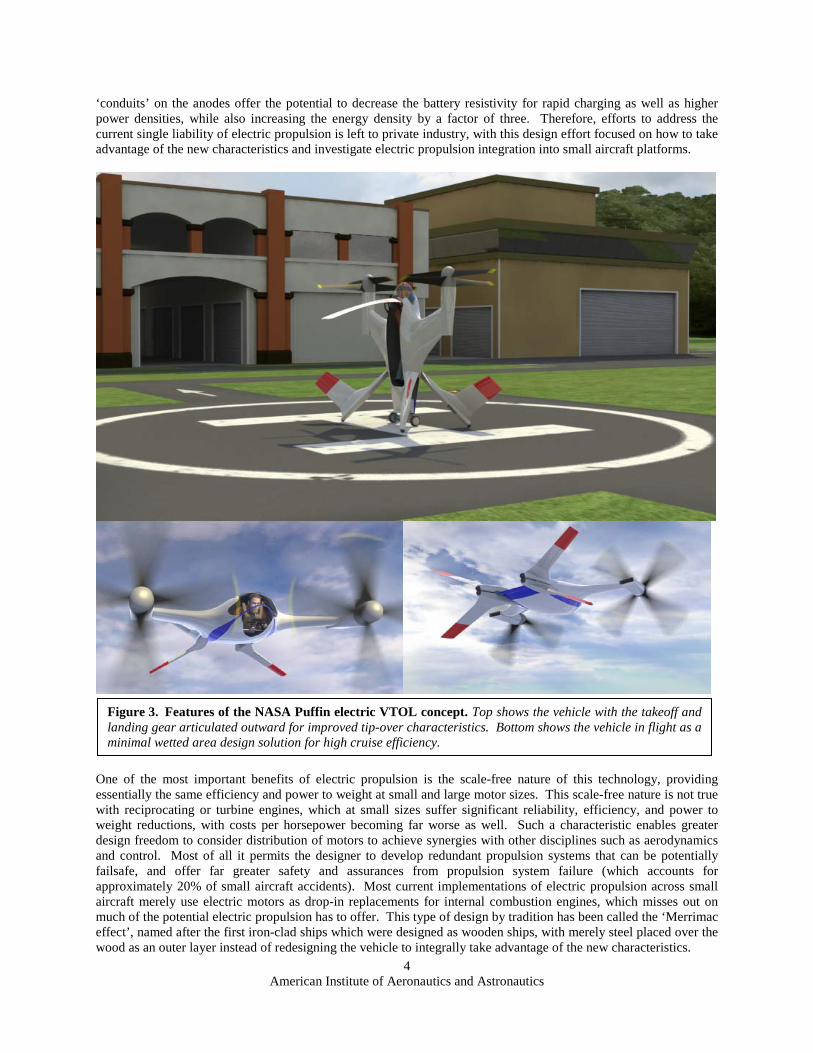
Figure 3. Features of the NASA Puffin electric VTOL concept. Top shows the vehicle with the takeoff and landing gear articulated outward for improved tip-over characteristics. Bottom shows the vehicle in flight as a minimal wetted area design solution for high cruise efficiency.
American Institute of Aeronautics and Astronautics
5
II. Concept Benefits A zero emission, highly efficient, highly reliable, ultra low noise VTOL capability would be a game changer compared to existing close proximity flight capabilities, for both unmanned and manned applications. The benefits described for this vehicle permit synergistic integration which reduces the penalty of current electric energy storage from a factor of 65 (the current difference in energy storage density compared to hydrocarbon fuels), to merely a factor of 3. This is due to 3x increased motor efficiency, 2x engine specific weight improvement, 2x engine-out sizing reduction for a VTOL lift system, 1.3x high/hot engine sizing reduction, and 1.4x fuel system installation weight reduction compared to liquid (including containment, unusable fuel, and plumbing weight reductions). Therefore, when battery energy density increases from the current lithium phosphate capacity of 200 to 600 W hr/kg, the other benefits of electric propulsion permit parity between electric and hydrocarbon energy systems. This 3 times increase in battery energy density is anticipated to occur within the next 5 to 10 years. However, this comparison is based purely on a performance comparison and does not take into account certain characteristics of electric that offer increased value for certain missions. Key among these factors is the ability to achieve emission-free green operation, nearly zero engine noise, and variable speed operation at maximum power. Therefore there are certainly better missions than others to apply this new technology, where these benefits are necessary factors towards mission success. Maximizing the potential benefit of electric propulsion is dependent on applying this technology to synergistic mission concepts. The vehicle missions with the most benefit include those which constrain environmental impact (or limit noise, exhaust, or emission signatures) are short range, or where large differences exist in the propulsion system sizing between takeoff and cruise conditions. This is the reason why electric propulsion is specifically being applied to On-Demand aviation close proximity vehicles that require these features, without the current limit on range (due to poor battery specific energy) being a significant issue. Electric propulsion offers the following unique capabilities that other propulsion systems can’t provide,
Elimination of engine noise and emissions. While engine noise is almost completely eliminated through the use of electric motors, other propulsion noise (such as the prop-rotor) is also important for achieving ultra low noise, close proximity operations. This design effort integrates the electric power-train to a 400 ft/sec tip-speed prop-rotor (compared to 700-800 ft/sec for conventional rotors and propellers), since noise varies to approximately the 4.5 power of the tip-speed.
Drastic reduction in engine cooling and radiated heat. Even small electric motors are able to achieve efficiencies greater than 90%, with only 5-10% of the engine energy radiated as heat. Thermal engines have efficiencies of approximately 25-30%, with up to 75% of their energy radiated as heat. The Puffin electric motor system (including the belt gear reduction system) has a 92% efficiency. Therefore instead of suffering from 15 to 20% of the total drag coming from cooling losses (as is standard in small aircraft), less than 3% of the total drag is associated with cooling drag.
Drastic reduction in vehicle vibration levels. This translates to greater comfort for manned vehicles, or improved sensor platform sensitivity for unmanned vehicles. Application of electric propulsion to this tail-sitter design permits VTOL capability while achieving a vibration-free cruise far superior to helicopter solutions due to rotor flow symmetry. The elimination of engine impulse loads feeding into propeller or rotor systems also alleviates gearbox reliability issues.
Drastic improvement in reliability and operating costs. Small turbine or reciprocating engines are notoriously unreliable, inefficient, and require frequent maintenance, with many UAV engines experiencing engine life of less than 100 hours. Brushless electric motors have a single moving part with no contact between surfaces, which eliminates any component wear. The operating fuel/energy cost is a factor of 6 times lower for electrical versus hydrocarbon fuel, due to achieving 3 times the engine efficiency and the reduced cost of electricity versus petroleum products.
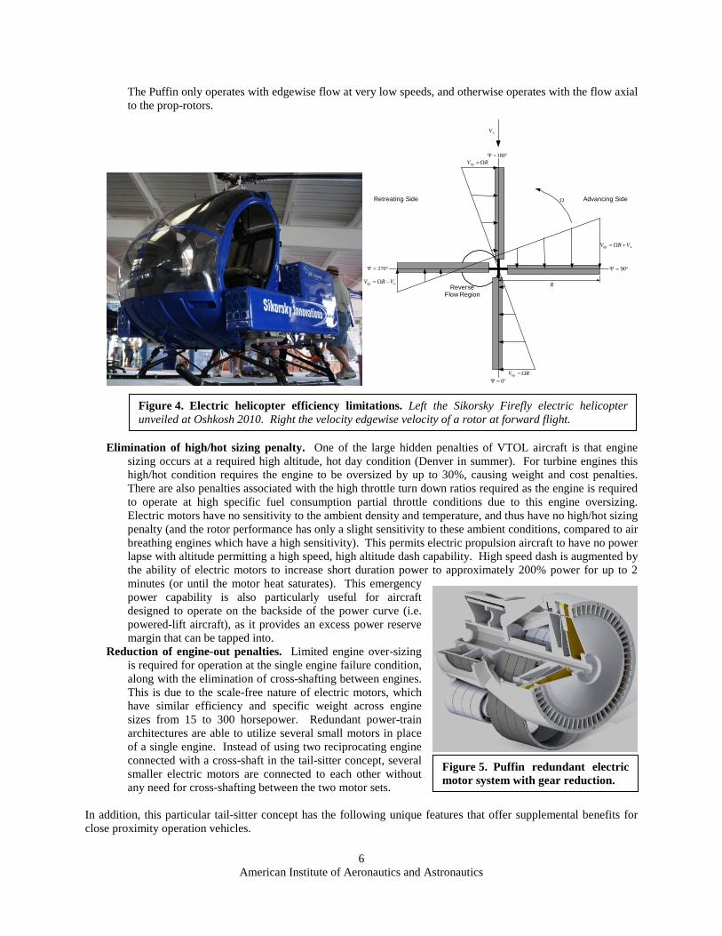
Variable speed output at full power, for improved cruise efficiency at low tip-speed. While helicopters have long pursued variable speed gearboxes and slowed rotors to increase the cruise efficiency, electric motors provide the equivalent of a continuously variable transmission over a 50% rpm operating range with no loss in efficiency and no gearbox weight. Slowing the prop-rotor in a tail-sitter vehicle in cruise has relatively minor prop-rotor stability issues compared to asymmetric helicopter slowed rotors, while permitting an approximately 25% reduction in cruise power required due to operation at optimum advance ratios (tip speed relative to cruise speed). But electric propulsion can not merely be added to existing helicopters and achieve this benefit due to limitations from retreating blade stall with edgewise rotor flight.
American Institute of Aeronautics and Astronautics
6
The Puffin only operates with edgewise flow at very low speeds, and otherwise operates with the flow axial to the prop-rotors.
°=Ψ 0
°=Ψ 270
°=Ψ 180
°=Ψ 90
Ω
∞V
RVtip Ω=
RVtip Ω=
∞−Ω= VRVtip
∞+Ω= VRVtip
RReverseFlow Region
Advancing SideRetreating Side
Elimination of high/hot sizing penalty. One of the large hidden penalties of VTOL aircraft is that engine
sizing occurs at a required high altitude, hot day condition (Denver in summer). For turbine engines this high/hot condition requires the engine to be oversized by up to 30%, causing weight and cost penalties. There are also penalties associated with the high throttle turn down ratios required as the engine is required to operate at high specific fuel consumption partial throttle conditions due to this engine oversizing. Electric motors have no sensitivity to the ambient density and temperature, and thus have no high/hot sizing penalty (and the rotor performance has only a slight sensitivity to these ambient conditions, compared to air breathing engines which have a high sensitivity). This permits electric propulsion aircraft to have no power lapse with altitude permitting a high speed, high altitude dash capability. High speed dash is augmented by the ability of electric motors to increase short duration power to approximately 200% power for up to 2 minutes (or until the motor heat saturates). This emergency power capability is also particularly useful for aircraft designed to operate on the backside of the power curve (i.e. powered-lift aircraft), as it provides an excess power reserve margin that can be tapped into.
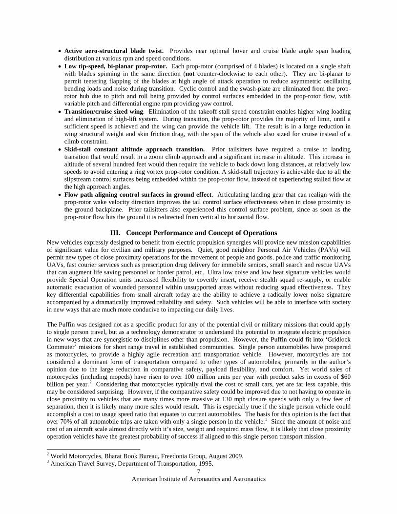
Reduction of engine-out penalties. Limited engine over-sizing is required for operation at the single engine failure condition, along with the elimination of cross-shafting between engines. This is due to the scale-free nature of electric motors, which have similar efficiency and specific weight across engine sizes from 15 to 300 horsepower. Redundant power-train architectures are able to utilize several small motors in place of a single engine. Instead of using two reciprocating engine connected with a cross-shaft in the tail-sitter concept, several smaller electric motors are connected to each other without any need for cross-shafting between the two motor sets.
In addition, this particular tail-sitter concept has the following unique features that offer supplemental benefits for close proximity operation vehicles.
Figure 4. Electric helicopter efficiency limitations. Left the Sikorsky Firefly electric helicopter unveiled at Oshkosh 2010. Right the velocity edgewise velocity of a rotor at forward flight.
Figure 5. Puffin redundant electric motor system with gear reduction.
American Institute of Aeronautics and Astronautics
7
• Active aero-structural blade twist. Provides near optimal hover and cruise blade angle span loading distribution at various rpm and speed conditions.
• Low tip-speed, bi-planar prop-rotor. Each prop-rotor (comprised of 4 blades) is located on a single shaft with blades spinning in the same direction (not counter-clockwise to each other). They are bi-planar to permit teetering flapping of the blades at high angle of attack operation to reduce asymmetric oscillating bending loads and noise during transition. Cyclic control and the swash-plate are eliminated from the prop-rotor hub due to pitch and roll being provided by control surfaces embedded in the prop-rotor flow, with variable pitch and differential engine rpm providing yaw control.
• Transition/cruise sized wing. Elimination of the takeoff stall speed constraint enables higher wing loading and elimination of high-lift system. During transition, the prop-rotor provides the majority of limit, until a sufficient speed is achieved and the wing can provide the vehicle lift. The result is in a large reduction in wing structural weight and skin friction drag, with the span of the vehicle also sized for cruise instead of a climb constraint.
• Skid-stall constant altitude approach transition. Prior tailsitters have required a cruise to landing transition that would result in a zoom climb approach and a significant increase in altitude. This increase in altitude of several hundred feet would then require the vehicle to back down long distances, at relatively low speeds to avoid entering a ring vortex prop-rotor condition. A skid-stall trajectory is achievable due to all the slipstream control surfaces being embedded within the prop-rotor flow, instead of experiencing stalled flow at the high approach angles.
• Flow path aligning control surfaces in ground effect. Articulating landing gear that can realign with the prop-rotor wake velocity direction improves the tail control surface effectiveness when in close proximity to the ground backplane. Prior tailsitters also experienced this control surface problem, since as soon as the prop-rotor flow hits the ground it is redirected from vertical to horizontal flow.
III. Concept Performance and Concept of Operations New vehicles expressly designed to benefit from electric propulsion synergies will provide new mission capabilities of significant value for civilian and military purposes. Quiet, good neighbor Personal Air Vehicles (PAVs) will permit new types of close proximity operations for the movement of people and goods, police and traffic monitoring UAVs, fast courier services such as prescription drug delivery for immobile seniors, small search and rescue UAVs that can augment life saving personnel or border patrol, etc. Ultra low noise and low heat signature vehicles would provide Special Operation units increased flexibility to covertly insert, receive stealth squad re-supply, or enable automatic evacuation of wounded personnel within unsupported areas without reducing squad effectiveness. They key differential capabilities from small aircraft today are the ability to achieve a radically lower noise signature accompanied by a dramatically improved reliability and safety. Such vehicles will be able to interface with society in new ways that are much more conducive to impacting our daily lives. The Puffin was designed not as a specific product for any of the potential civil or military missions that could apply to single person travel, but as a technology demonstrator to understand the potential to integrate electric propulsion in new ways that are synergistic to disciplines other than propulsion. However, the Puffin could fit into ‘Gridlock Commuter’ missions for short range travel in established communities. Single person automobiles have prospered as motorcycles, to provide a highly agile recreation and transportation vehicle. However, motorcycles are not considered a dominant form of transportation compared to other types of automobiles; primarily in the author’s opinion due to the large reduction in comparative safety, payload flexibility, and comfort. Yet world sales of motorcycles (including mopeds) have risen to over 100 million units per year with product sales in excess of $60 billion per year.2 Considering that motorcycles typically rival the cost of small cars, yet are far less capable, this may be considered surprising. However, if the comparative safety could be improved due to not having to operate in close proximity to vehicles that are many times more massive at 130 mph closure speeds with only a few feet of separation, then it is likely many more sales would result. This is especially true if the single person vehicle could accomplish a cost to usage speed ratio that equates to current automobiles. The basis for this opinion is the fact that over 70% of all automobile trips are taken with only a single person in the vehicle.3
2 World Motorcycles, Bharat Book Bureau, Freedonia Group, August 2009.
Since the amount of noise and cost of an aircraft scale almost directly with it’s size, weight and required mass flow, it is likely that close proximity operation vehicles have the greatest probability of success if aligned to this single person transport mission.
3 American Travel Survey, Department of Transportation, 1995.
American Institute of Aeronautics and Astronautics
8
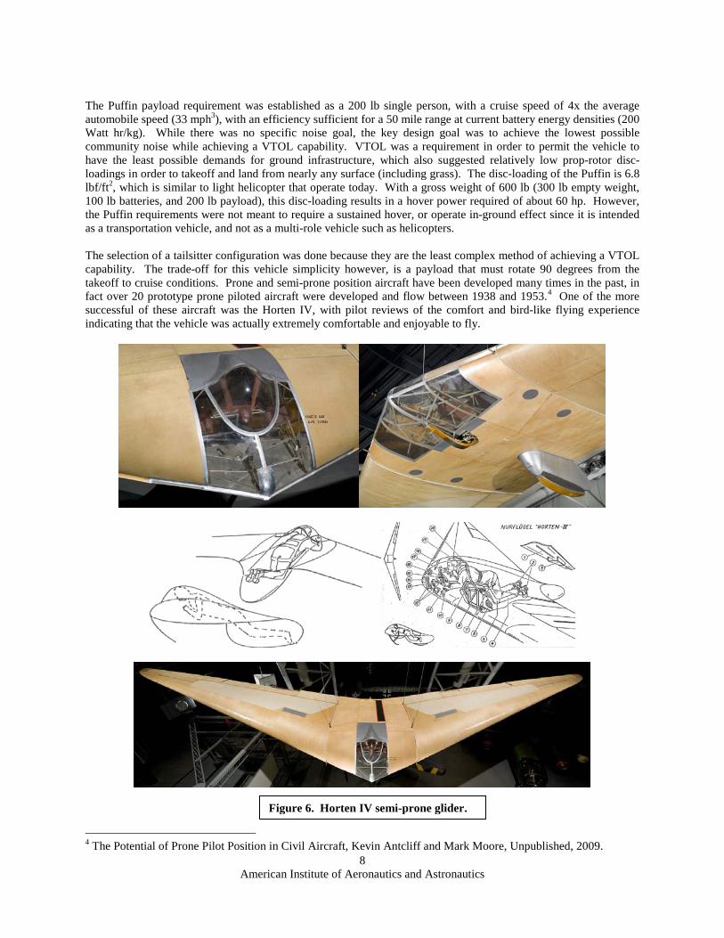
The Puffin payload requirement was established as a 200 lb single person, with a cruise speed of 4x the average automobile speed (33 mph3), with an efficiency sufficient for a 50 mile range at current battery energy densities (200 Watt hr/kg). While there was no specific noise goal, the key design goal was to achieve the lowest possible community noise while achieving a VTOL capability. VTOL was a requirement in order to permit the vehicle to have the least possible demands for ground infrastructure, which also suggested relatively low prop-rotor disc-loadings in order to takeoff and land from nearly any surface (including grass). The disc-loading of the Puffin is 6.8 lbf/ft2, which is similar to light helicopter that operate today. With a gross weight of 600 lb (300 lb empty weight, 100 lb batteries, and 200 lb payload), this disc-loading results in a hover power required of about 60 hp. However, the Puffin requirements were not meant to require a sustained hover, or operate in-ground effect since it is intended as a transportation vehicle, and not as a multi-role vehicle such as helicopters. The selection of a tailsitter configuration was done because they are the least complex method of achieving a VTOL capability. The trade-off for this vehicle simplicity however, is a payload that must rotate 90 degrees from the takeoff to cruise conditions. Prone and semi-prone position aircraft have been developed many times in the past, in fact over 20 prototype prone piloted aircraft were developed and flow between 1938 and 1953.4
One of the more successful of these aircraft was the Horten IV, with pilot reviews of the comfort and bird-like flying experience indicating that the vehicle was actually extremely comfortable and enjoyable to fly.
4 The Potential of Prone Pilot Position in Civil Aircraft, Kevin Antcliff and Mark Moore, Unpublished, 2009.
Figure 6. Horten IV semi-prone glider.
American Institute of Aeronautics and Astronautics
9
Cruise performance of the Puffin based on standard conceptual design analysis methods, combined with momentum blade element analysis for the prop-rotor. Component efficiencies and more detailed analysis was also incorporated to improve the analysis accuracy, since this vehicle is rather unconventional and outside of the regression-based method database. Aerodynamic analysis was calibrated to the Arnold AR-5 aircraft since a large amount of aerodynamic data was available for that aircraft, and it is very similar in size and weight. The AR-5 established the FAI world speed record for an aircraft under 660 lbs, traveling 213 mph with less than 65 hp. Analysis indicated an L/D of 17.8 at 100 mph and 14.5 at 150 mph. While the wetted area of the Puffin was slightly less than the AR-5 aircraft, yet the parasite drag of the Puffin was higher due to the high degree of laminar flow that was achieved with the AR-5. Cruise power was estimated less than 20 hp at the 100 mph cruise speed, which provids approximately 50 miles range to meet that design objective. One interesting feature of the Puffin due to the electric propulsion system, would be the ability to extract approximately 120 hp for approximately 1 minute (until the electric motors become heat saturated), and achieve a dash speed of greater than 250 mph, even at sea level altitudes. Since electric propulsion experiences no lapse rate with altitude, flight at higher altitudes (with oxygen systems) could yield far higher cruise and dash speeds (if you can allow for enough battery weight to get you to altitude!) The goal of achieving a 10x reduction of perceived noise from the lowest noise helicopters today is based on comparison to the MD 500 NOTAR and Kaman Kmax helicopters that achieve approximately 82 db certification levels. While a portion of the comparative benefit is purely due to a far lower mass vehicle (600 lbs gross weight versus 3000 lbs and above), the majority of the noise decrement is based on incorporation of a low tip speed prop-rotor system. It is unknown to what level the community noise must be reduced for accommodation of public acceptance of Puffin-like vehicle, based on a noise perspective. However, the ability to meet locality noise standards, and future airport boundary standards at any adjoining property to the flight operations is expected to be a minimally acceptable criteria. Such criteria would suggest than the noise at the property boundary would need to be at the 55 to 60 db level, which is in the range of the 10x noise reduction goal. Concept of Operations (ConOps) were developed for the Puffin, with design of a high capacity Heliport to better understand how such vehicles might interface with communities to minimize flight risk and community noise, while meeting the existing FAA Helipad standards. Figure 8 shows a rendering of this close proximity airfield as part of a business park that accommodates up to 150 based Puffin aircraft (with covered storage), as well as an additional 50 visiting aircraft within a 6 acre site. The concept was developed with a dual-use functionality, with office space above the vehicle garages, while maintaining a large open area in the center with the buildings providing acoustic shielding to the remainder of the community. Two helipads are used for non-interfering takeoff and landings, with ground taxi patterns that provide one-way paths to avoid vehicle conflict during peak operation times when takeoffs and departures could occur at intervals of less than one minute each, altering between the takeoff and landing pads. The actual transition from hover to full forward flight takes place in less than 15 seconds.
IV. Detailed Concept Analysis The Puffin technology demonstration concept is being studied through the use of higher-order analysis tools that can capture physics-based effects in aero-acoustics and prop-rotor dynamics while yielding highly credible results. The following research activities have been performed. Since reports and papers are available for each of the individual detailed analyses, no in-depth review is performed of these studies in this paper. Additional analyses are ongoing in the aeroacoustics discipline, since the key objective is to accomplish highly credible noise predictions that can substantiate the ability to achieve a 10x reduction in the perceived noise levels compared to today’s quietest
Figure 7. High capacity Heliport design.
American Institute of Aeronautics and Astronautics
10
helicopters. Sub-scale testing of low tip speed prop-rotors is also on-going at Georgia Tech Research Institute of several different prop-rotor designs across a range of 400 to 500 ft/sec tip speeds. These tests will provide calibration data sets for the analysis tools, as well as audible signatures that can be compared to assess other noise factors such as the noise annoyance (which is outside of simply achieving a low decibel signature).
• Conceptual Design and Performance Analysis (Mark Moore, NASA Langley) Concept development and geometric configuration development using Vehicle Sketch Pad5
• Integrated High Fidelity Aerodynamics and Aeroacoustics
(VSP), and performance analysis using blade element momentum analysis for the prop-rotor, drag build-up and performance utilizing the FLight Optimization and Performance (FLOPS) tool, and induced drag analysis utilizing Vorlax vortex lattice analysis coupled to regressed wingtip propeller interactions. Figure 8 shows the vehicle geometry tool VSP being used for vehicle sizing and layout.
6
optimization of blade planform characteristics, Overflow aerodynamic CFD solutions, and WopWop aeroacoustic analysis. Figure 9 shows a
(Jeremy Bain, Georgia Tech) Prop-rotor analysis including a Pareto mapping and
prediction of the Overflow/WopWop acoustic comparison to the HART sub-scale experimental test data of a typical tip speed rotor (717 ft/sec) versus the Puffin tip speed of 400 ft/sec. The sunflower pattern of the Puffin acoustics is a result of constructive and destructive interference between the two prop-rotors on either side of the vehicle wingtip. This analysis showed an approximately 30 db reduction, however, did not account for all broadband noise sources. Subsequent efforts will account for the broadband sources, since at lower tip speeds their contributions become an increasingly significant noise source.
• Redundant Electric Power train Design7
pole count motor. Integral gear reductions were also analyzed including both planetary gear system and redundant belt system solutions. Figure 10 shows one of the failure tree comparisons between the quad-motor (on the left), and the high pole count motor (on the right). The high pole
(Bryan Seegers, Mdot Engineering) Detailed failure mode analysis, CAD build-up and design of the redundant electric motor system with comparison of 3 different architectures, including integrated quad-motor, a ring motor, and a high
count motor was the down-selected power train architecture, in combination with a belt system, as shown in Figure 5. The overall motor gearbox efficiency was estimated to 92%, with a power to weight of better than hp per pound at the nominal 30 hp per nacelle rating, with an allowance of failure of any 2 poles or any two belts. Essentially each individual power system offers the equivalent of a multi-engine rating to accomplish the safety goal, and eliminate the need for cross-shafting between the prop-rotor nacelles.
• Prop-Rotor Structural Dynamics Analysis8
5 Vehicle Sketch Pad: A Parametric Geometry Modeler for Conceptual Aircraft Design, Andrew Hahn, AIAA Paper 2010-657.
(Jinwei Shin, NIA) Development of a multi-body dynamics model of the teetering bi-planar prop-rotor system, with study of the aeroelastic response and loading of the system under various flight conditions. The MBDyn analysis tool was utilized, in combination with the aerodynamic Overflow analysis results in
6 Aerodynamic and Acoustic Design of a Low Noise Dual Rotor Tail-sitter, Jeremy Bain and Kyle Collins, AHS, 2009. 7 High Efficiency Redundant Electric Power System, Bryan Seegers, Final Presentation, Sept 28 2009. 8 Multibody Dynamics Model of a VTOL Teetering Rotor, Jinwei Shin and Pierangelo Masarati, AHS, 2009.
Figure 8. Geometric layout using Vechicle Sketch Pad.
Figure 9. Puffin acoustic signature in hover compared to HART data.
Figure 10. Failure tree analysis of competing electric motor designs.
American Institute of Aeronautics and Astronautics
11
vertical, transition, and horizontal flight modes. Comparison was made to non-teetering systems to showcase the difference in aeromechanic characteristics, and specifically the approximately 10x difference in oscillating blade bending moments that results from permitting a teetering flapping motion during the high angle of attack transition flight. Figure 11 shows this difference in loading between the flapping and non-flapping systems. Addition effort is ongoing to understand the scale effects of the oscillating bending to determine whether small prop-rotor systems have advantages that can be utilized in order to achieve further reductions of complexity in other small VTOL vehicles.
• Tail-sitter Stability, Control and Transition9
wash streamtube to determine the local velocities at the tail surfaces. Control surface forces were calculated with incorporation into a non-linear 6 Degree of Freedom simulator with corridor exploration of transition speeds and vehicle angle of attack. The results indicated that
(Buddy Michini, MIT) Stability and control analysis incorporating blade element modeling of the prop-rotor along with modeling of the contraction of the prop-rotor
the Puffin had sufficient control through a sufficiently wide transition corridor, purely through the tail and wing slipstream controllers without incorporation of cyclic control on the prop-rotors. Parametric studies of various wing areas, levels of thrust, and tail areas were performed to guide further optimization of the planform.
• Sub-scale prototype testing10
cost Remote Control (RC) based equipment effort, in part to determine the value of low cost rapid
(Todd Hodege, NIA) In order to assess the simplifying assumptions of the stability and control analysis, a 1/3 scale demonstrator was built to perform experimental flights and determine the transition control characteristics. This was done as a low
prototyping experiments. Hover testing has been performed, with the research vehicle having the ability to fly both with and without prop-rotor cyclic control to determine the need for active propulsion control. Transition flight has not yet been performed.
V. Conclusion Research has been conducted to determine the potential of electric propulsion to provide new breakthrough capabilities for close proximity VTOL flight operations for small aircraft. Such vehicles have the potential of being far lower noise than any man carrying VTOL aircraft currently in production. Electric propulsion has a number of unique characteristics that foster the ability to achieve synergistic integration with other disciplinary components and suggest that future electric propulsion vehicles will have offer significantly greater design freedom, due to the scale-free nature of this new technology. The Puffin research concept has been analyzed in a multi-disciplinary way while incorporating higher-order analysis in areas where the vehicle is substantially different than existing aircraft.
Acknowledgments The author would like to thank Andy Hahn, Bill Fredericks, Casey Burley, Ken Goodrich, Dennis Bushnell, Rich Antcliff, Kevin Antcliff, and Charlie Harris for their support and insight which has helped to develop this concept. The author would also like to thank the Puffin development team for their excellent analysis during the development of this concept including, Jeremy Bain of Georgia Tech, Todd Hodges and Jinwei Shin of the National Institute of Aerospace, Bryan Seegers of Mdot Propulsion, and Buddy Michini and Jonathan How of MIT. Jeremy Bain has particularly been a major contributor, who has added tremendous value to this concept exploration. 9 Puffin Control Analysis Final Report, Buddy Michini and Jonathan How, Jan 13 2010. 10 Puffin Subscale Flight Demonstrator, Todd Hodges, NIA, Jul 30 2010.
Figure 13. Puffin 1/3 scale flight demonstrator.
Figure 11. Oscillating bending moment for a fixed and teeting prop-rotor.
Figure 12. Blade element and wake propagation model for stability and control analysis.
American Institute of Aeronautics and Astronautics