33
Nat 5: Electricity and Energy 1

Nat 5: Electricity and Energy 1
2 Nat 5: Electricity and Energy
3.1 Conservation of Energy
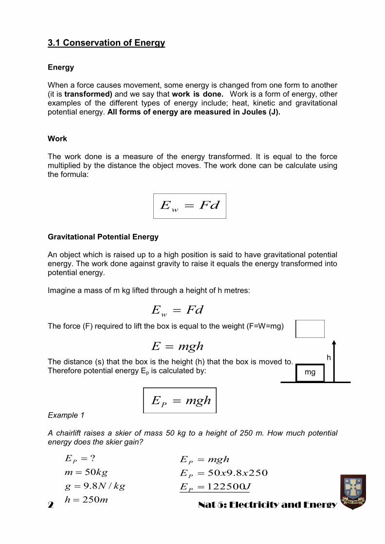
Energy When a force causes movement, some energy is changed from one form to another (it is transformed) and we say that work is done. Work is a form of energy, other examples of the different types of energy include; heat, kinetic and gravitational potential energy. All forms of energy are measured in Joules (J). Work The work done is a measure of the energy transformed. It is equal to the force multiplied by the distance the object moves. The work done can be calculate using the formula: Gravitational Potential Energy An object which is raised up to a high position is said to have gravitational potential energy. The work done against gravity to raise it equals the energy transformed into potential energy. Imagine a mass of m kg lifted through a height of h metres: The force (F) required to lift the box is equal to the weight (F=W=mg) The distance (s) that the box is the height (h) that the box is moved to. Therefore potential energy Ep is calculated by: Example 1 A chairlift raises a skier of mass 50 kg to a height of 250 m. How much potential energy does the skier gain?
FdEw
h
mg
mghE
mghE
FdE
P
w
JE
xxE
mghE
P
P
P
122500
2508.950
mh
kgNg
kgm
EP
250
/8.9
50
?

Nat 5: Electricity and Energy 3
Example 2 A pendulum bob is raised to a height of 20cm and has a mass of 50 g. calculate the potential energy gained by the pendulum as it is raised to this height.
Kinetic Energy Kinetic energy is the energy associated with a moving object. The kinetic energy that an object has is determined by the mass (m) of the object and the speed (v) squared. It can be calculated using the formula: Example How much kinetic energy does a car of mass 1000 kg have when it is travelling at 20 ms
-1?
Conservation of Energy Energy cannot be created or destroyed, but can be changed from one form into another. For example, the force of friction causes kinetic energy to be transformed into heat energy or gravitational potential energy can be transformed into kinetic energy in theme parks. Roller coasters have loads of Physics to enjoy!
2
2
1mvEK
JE
xxE
mvE
K
K
K
200000
2010002
1
2
1
2
2
mh
kgm
EP
2.0
05.0
?
JE
xxE
mghE
P
P
P
098.0
2.08.905.0
120
1000
?
msv
kgm
EK

4 Nat 5: Electricity and Energy
Example1 A stone of mass 2 kg is dropped from a height of 5 m. Calculate the velocity of the stone as it hits the ground. Air resistance is negligible. At a height of 5 m the stone has some gravitational potential energy:
As there is no air resistance all of the potential energy will be converted to kinetic energy.
Example 2 A child’s sling shot toy is used to fire a 10g mass at a target. The slingshot is pulled back a distance of 15cm using a force of 4N. If all of the work done in pulling the sling shot back is converted into kinetic energy calculate the speed of the 10g mass as it leaves the sling shot. Efficiency Machines can be used to transform one kind of energy into another. For example, an electric motor transforms electrical energy into kinetic energy. This energy might be further transformed into potential energy if the motor is used to drive a lift. However, not all the electrical energy which is supplied to the motor will be trans-formed into the final useful form of energy. Some may be transformed into heat, due to friction, and sound. Although no energy has been destroyed, some is ‘wasted’ as it cannot be used. This makes the machine inefficient. Efficiency is measured by expressing the useful energy output as a percentage of the total energy input.
1
2
2
2
2
11
120
005.06.0
01.02
115.04
2
1
msv
v
v
xvxx
mvFxd
EE KW
JE
xxE
mghE
P
P
P
98
58.92
1
2
2
2
9.9
98
22
198
2
198
msv
v
xvx
mv
EE KP
mh
kgNg
kgm
EP
5
/8.9
2
?
?
4
15.0
01.0
v
NF
md
kgm
Nat 5: Electricity and Energy 5
3.2 Charge Carriers and Electric Fields
There are two types of electrical charge; positive and negative. Objects can become charged by rubbing them. During this process negative charges (electrons) can be transferred to the material (making it negatively charged) or the electrons can be removed from the material (making it positively charged). The properties of charged substances can be investigated using polythene and acetate rods. When an acetate rod is rubbed it becomes positively charged and when a polythene rod is rubbed it becomes negatively charged. If two polythene rods are brought together they will repel (similarly for two acetate rods). If a polythene and an acetate rod are brought together they will attract. Opposite charges attract, like charges repel.
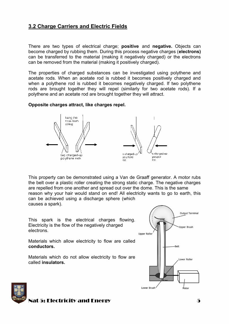
This property can be demonstrated using a Van de Graaff generator. A motor rubs the belt over a plastic roller creating the strong static charge. The negative charges are repelled from one another and spread out over the dome. This is the same reason why your hair would stand on end! All electricity wants to go to earth, this can be achieved using a discharge sphere (which causes a spark). This spark is the electrical charges flowing. Electricity is the flow of the negatively charged electrons. Materials which allow electricity to flow are called conductors. Materials which do not allow electricity to flow are called insulators.

6 Nat 5: Electricity and Energy
Electric Current Electric current is a measure of the flow of charge around a circuit and depends on the amount of charge passing any point in a circuit every second. Electric current (I) is measured in amperes, A. Electric charge (Q) is measured in coulombs, C. Time (t) is measured in seconds, s. Example Calculate the electric current in a circuit if 3 C of charge pass a point in a circuit in a time of 1 minute. Alternating Current (a.c.) and Direct Current (d.c.)
All power supplies can be grouped into one of two categories depending on the way that they supply energy to the charges in a circuit. A d.c. supply produces a flow of charge through a circuit in one direction only. An a.c. supply produces a flow of charge which regularly reverses its direction through a circuit. The direction of the current depends upon which side of the battery / supply terminal is positive and which is negative. U.K. mains electricity is an alternating supply with a quoted voltage of 230 V and a frequency of 50 Hz. This means that it completes one cycle 50 times per second.
The peak voltage for an alternating supply cannot be used as a measure of its effective voltage as the voltage is only at that peak value for a short space of time. The effective (quoted) voltage of an a.c. supply is less than the peak value. For example, an alternating supply with a peak value of 10 V does not supply the same power to a circuit as a direct supply of 10 V. The effective voltage for an a.c. supply would be 70 % of the peak voltage. 70% of 10 V = 7 V.
ItQ
AI
I
t
QI
05.0
60
3
Varying a.c. supply Steady d.c. supply
Volts (V)
Time (s) Time (s)
peak Volts (V)
st
CQ
I
60
3
?
Nat 5: Electricity and Energy 7
3.3 Potential Difference and Circuits
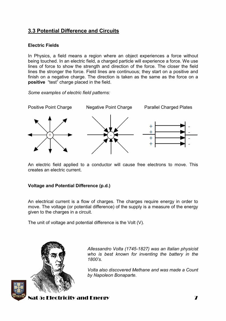
Electric Fields In Physics, a field means a region where an object experiences a force without being touched. In an electric field, a charged particle will experience a force. We use lines of force to show the strength and direction of the force. The closer the field lines the stronger the force. Field lines are continuous; they start on a positive and finish on a negative charge. The direction is taken as the same as the force on a positive “test” charge placed in the field. Some examples of electric field patterns:
An electric field applied to a conductor will cause free electrons to move. This creates an electric current. Voltage and Potential Difference (p.d.) An electrical current is a flow of charges. The charges require energy in order to move. The voltage (or potential difference) of the supply is a measure of the energy given to the charges in a circuit. The unit of voltage and potential difference is the Volt (V).
Allessandro Volta (1745-1827) was an Italian physicist who is best known for inventing the battery in the 1800’s. Volta also discovered Methane and was made a Count by Napoleon Bonaparte.
Positive Point Charge Negative Point Charge Parallel Charged Plates

8 Nat 5: Electricity and Energy
Circuit Symbols Circuit symbols are used in electrical circuits to represent circuit components or devices making them easier to draw and understand. Some of the circuit symbols that you will need to know are shown below.
Meters
Ammeter Voltmeter Cell Battery
Lamp Resistor Variable Resistor Fuse
Switch LDR (light dependent resistor)
Thermistor Capacitor
Diode Photovoltaic LED (light emitting diode)
Placing An Ammeter Electric current is measured using an ammeter which is connected in series with the component. Ammeter measures current through the lamp.
Placing A Voltmeter Potential difference (p.d.), or voltage, is measured using a voltmeter which is connected in parallel with a component. The voltmeter measures the voltage (p.d.) across the lamp.
Relay

Nat 5: Electricity and Energy 9
Current and Potential Difference in Series Circuits The current is the same at all points in a series circuit. One way to remember this is that there is only one path for the current to flow. The sum of the potential difference across the components in a series circuit is equal to the voltage of the supply. Current and Potential Difference in Parallel Circuits In a parallel circuit the current has more than one path to follow. This means that the supply current splits through each parallel branch. The potential difference across components is the same for all components.
IA = IB= IC
VS= V1+ V2
VS = V1= V2
IS= IA+ IB

10 Nat 5: Electricity and Energy
Household Wiring and The Ring Circuit The wiring in a house connects all appliances together in parallel. This is so that each has the mains supply of 230 volts across it and also so that they can all be used independently The power sockets in a house are connected by means of a ring circuit. In a ring circuit the live, neutral and earth wires form a loop of cable going from the consumer unit to all of the sockets in turn and then back to the consumer unit. There are several advantages for wiring the house in this way: the cables can be thinner because there are
two paths for the current each part of the cable carries less current a ring circuit is more convenient since sockets can be placed anywhere
V is Voltage, measured in Volts (V) I is current, measured in Amperes (A) R is resistance, measured in Ohm’s (Ω)
IRV
100
1060
63
R
xR
I
VR
IRV
Electrical Resistance Ohm’s Law Resistance is a measure of the opposition of a circuit component to the current through that component. The greater the resistance of a component, the smaller the current through that component. All normal circuit components have resistance and the resistance of a component is measured using the relationship: This relationship is known as Ohm’s Law, named after a German physicist, Georg Ohm. For components called resistors, the resistance remains approximately constant for different values of current. This means that the V/I = constant (R). Example Find the resistance of the lamp in the circuit diagram below.

Nat 5: Electricity and Energy 11
General Circuit Problems Example 1 In the circuit below the ammeter reads 0.8 A, the current through the lamp is 0.3A and the voltmeter reads 6V. (a) Is this a series or parallel circuit?
(b) (i) What are the current values at X and Y? (ii) What is the potential difference across the lamp? (a) Parallel Circuit. b) (i) X = 0.8 A and Y = 0.5 A. (ii) Voltage across lamp = 6 V.
Example 2
An electric fire has three elements which can be switched on and off independently. The elements are connected in parallel to the mains supply. Each element draws a current of 0·3 A when switched on.
(a) Determine the voltage across the middle element.
(b) Calculate the total current flowing from the supply when two of the elements are switched on.
(c) Calculate the maximum current drawn from the mains by the fire.
(a) 230V (In parallel the voltage remains the same across each branch) (b) 0.6A (two branches each drawing 0.3A gives 0.3 + 0.3 = 0.6A) (c) 0.9A
12 Nat 5: Electricity and Energy
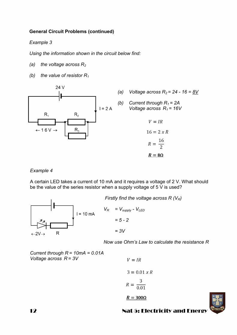
General Circuit Problems (continued) Example 3 Using the information shown in the circuit below find: (a) the voltage across R2 (b) the value of resistor R1
(a) Voltage across R2 = 24 - 16 = 8V (b) Current through R1 = 2A Voltage across R1 = 16V
Example 4 A certain LED takes a current of 10 mA and it requires a voltage of 2 V. What should be the value of the series resistor when a supply voltage of 5 V is used?
Firstly find the voltage across R (VR) VR = Vsupply - VLED
= 5 - 2 = 3V Now use Ohm’s Law to calculate the resistance R
Current through R = 10mA = 0.01A Voltage across R = 3V
Nat 5: Electricity and Energy 13
RT= R1+ R2 + R3
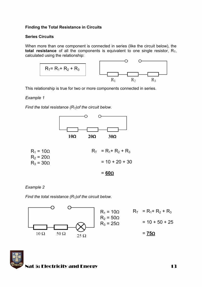
Finding the Total Resistance in Circuits Series Circuits When more than one component is connected in series (like the circuit below), the total resistance of all the components is equivalent to one single resistor, RT, calculated using the relationship: This relationship is true for two or more components connected in series. Example 1 Find the total resistance (RT)of the circuit below. Example 2 Find the total resistance (RT)of the circuit below.
10Ω 20Ω 30Ω
RT = R1+ R2 + R3
= 10 + 20 + 30
= 60Ω
R1 = 10Ω R2 = 20Ω
R3 = 30Ω
RT = R1+ R2 + R3
= 10 + 50 + 25
= 75Ω
R1 = 10Ω R2 = 50Ω
R3 = 25Ω

14 Nat 5: Electricity and Energy
Parallel Circuits When more than one component is connected in parallel, the total resistance of all the components is equivalent to one single resistor, RT, calculated using the relationship: This relationship is true for two or more components connected in parallel. Example 1 Find the total resistance (RT) of the circuit below. Example 2 Find the total resistance (RT) of the circuit below.
321
1111
RRRRT
R1
R2
R3
30Ω
60Ω

Nat 5: Electricity and Energy 15
Combination Circuits Example 1 Calculate the total resistance between X and Y. Step 1: Find the total resistance of the parallel section:
Step 2: Add 20 Ω to 25 Ω connected in series. RT =R1 + R2
RT = 20 +25 RT = 45 Ω Example 2 Calculate the total resistance between X and Y.
The two 15Ω resistors are in series
with each other and can therefore be simply added together.
15 + 15 = 30Ω
The two 30Ω resistors are also in series with each other so;
30 + 30 = 60Ω
The two branches are in parallel so the total resistance can be calculated as follows;
20
20
11
100
1
25
11
111
21
T
T
T
T
R
R
R
RRR

16 Nat 5: Electricity and Energy
Potential Divider Circuits
A potential divider is a device or a circuit that uses two (or more) resistors or a variable resistor (potentiometer) to provide a fraction of the available voltage (p.d.) from the supply.
Fixed Resistance Variable Resistance The p.d. from the supply is divided across the resistors in direct proportion to their individual resistances. Take the fixed resistance circuit - this is a series circuit therefore the current is the same at all points. Isupply = I1 = I2 where I1 = current through R1 And I2 = current through R2
Using Ohm’s Law:
Hence
or and
Example Calculate the output p.d., Vout, from the potential divider circuit shown.
2
2
1
1
R
V
R
V
R
V
T
S R
VI
S
T
xVR
RV 1
1 SxV
RR
RV
21
11
2
1
2
1
R
R
V
V
VV
kR
kR
V
S
Out
20
15
10
?
2
1
VV
xV
xVRR
RVV
Out
Out
SOut
8
201510
10
21
11
Nat 5: Electricity and Energy 17
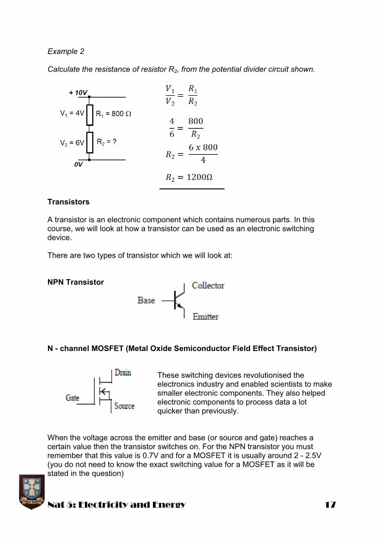
Example 2 Calculate the resistance of resistor R2, from the potential divider circuit shown.
Transistors A transistor is an electronic component which contains numerous parts. In this course, we will look at how a transistor can be used as an electronic switching device. There are two types of transistor which we will look at: NPN Transistor
N - channel MOSFET (Metal Oxide Semiconductor Field Effect Transistor)
These switching devices revolutionised the electronics industry and enabled scientists to make smaller electronic components. They also helped electronic components to process data a lot quicker than previously.
When the voltage across the emitter and base (or source and gate) reaches a certain value then the transistor switches on. For the NPN transistor you must remember that this value is 0.7V and for a MOSFET it is usually around 2 - 2.5V (you do not need to know the exact switching value for a MOSFET as it will be stated in the question)
18 Nat 5: Electricity and Energy
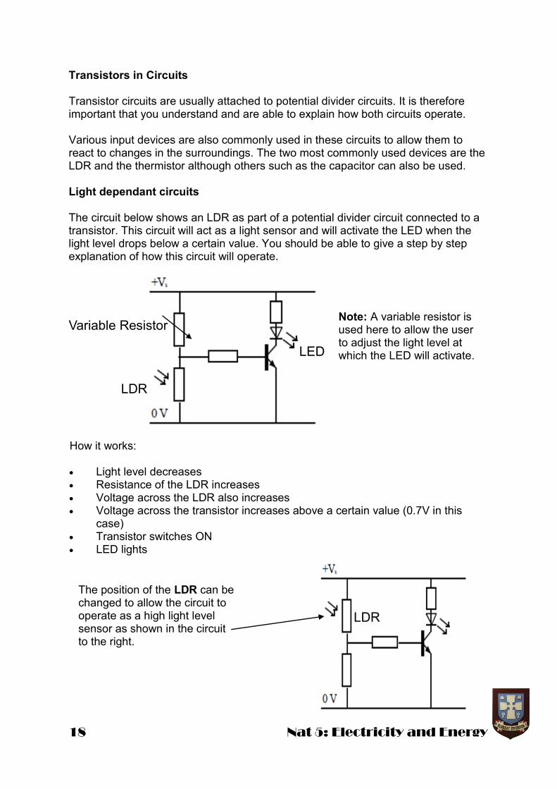
Transistors in Circuits Transistor circuits are usually attached to potential divider circuits. It is therefore important that you understand and are able to explain how both circuits operate. Various input devices are also commonly used in these circuits to allow them to react to changes in the surroundings. The two most commonly used devices are the LDR and the thermistor although others such as the capacitor can also be used. Light dependant circuits The circuit below shows an LDR as part of a potential divider circuit connected to a transistor. This circuit will act as a light sensor and will activate the LED when the light level drops below a certain value. You should be able to give a step by step explanation of how this circuit will operate.
LDR
Variable Resistor Note: A variable resistor is used here to allow the user to adjust the light level at which the LED will activate.
How it works: Light level decreases Resistance of the LDR increases Voltage across the LDR also increases Voltage across the transistor increases above a certain value (0.7V in this
case) Transistor switches ON LED lights
The position of the LDR can be changed to allow the circuit to operate as a high light level sensor as shown in the circuit to the right.
LED
LDR

Nat 5: Electricity and Energy 19
Temperature dependant circuits Thermistors can be used instead of LDRs to create temperature sensitive circuits. An example of a temperature sensing circuit that activates an LED when the temperature drops below a certain value is shown below.
Note: NPN Transistors are used here but MOSFETs can also be used.
Thermistor
How it works: Temperature decreases Resistance of the thermistor increases Voltage across the thermistor also increases Voltage across the transistor increases above a certain value (0.7V in this case) Transistor switches ON LED lights
Example 1 The circuit below is part of a temperature sensitive circuit that is used to operate a heater.
a) Explain how the circuit operates to switch on the heater when the temperature falls below a certain level. b) If the resistance of the variable resistor is now increased explain what effect this will have on the temperature at which the heater is switched on?
a) As the temperature decreases the resistance of the thermistor increases. The voltage across the thermistor also increases. This causes the voltage across the MOSFET to increase and when it reaches a certain value it allows current to flow to the relay. The relay switch will close and cause the heater to operate. b) If the resistance of the variable resistor is increased the thermistor will have to reach a higher value of resistance to switch on the MOSFET. The temperature at which the heater is switched on will therefore be lower.
20 Nat 5: Electricity and Energy
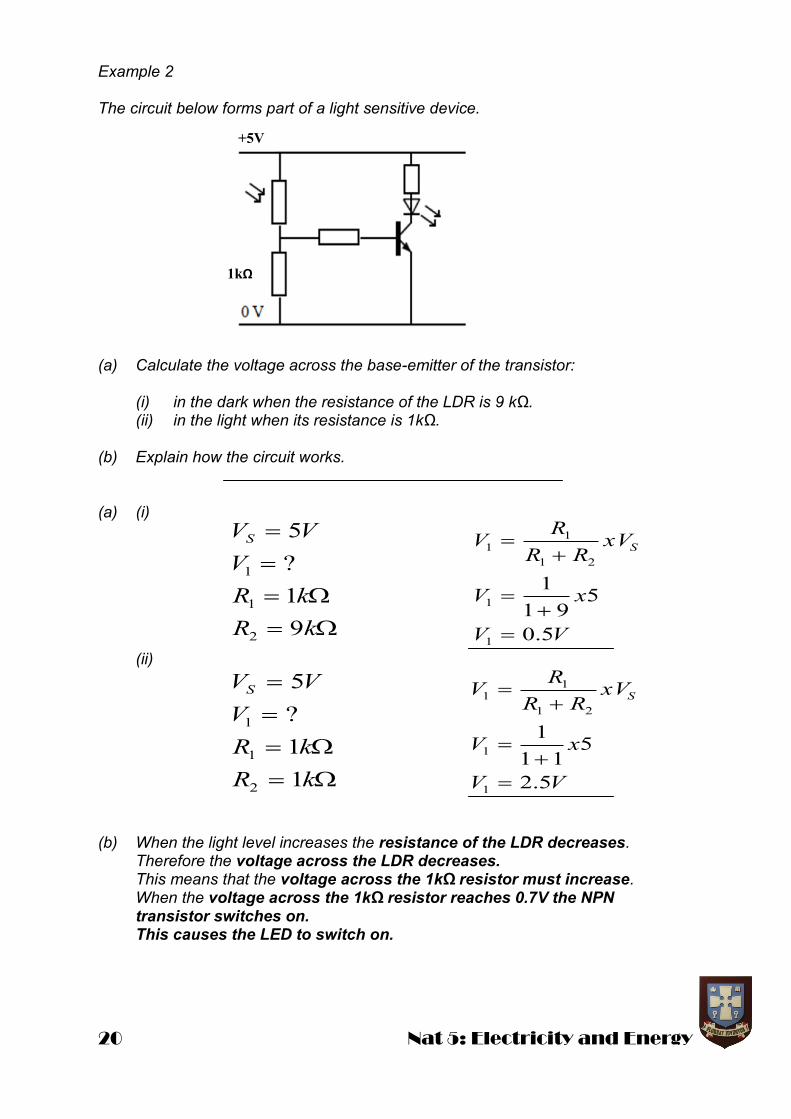
Example 2 The circuit below forms part of a light sensitive device. (a) Calculate the voltage across the base-emitter of the transistor: (i) in the dark when the resistance of the LDR is 9 kΩ. (ii) in the light when its resistance is 1kΩ. (b) Explain how the circuit works. (a) (i) (ii) (b) When the light level increases the resistance of the LDR decreases. Therefore the voltage across the LDR decreases. This means that the voltage across the 1kΩ resistor must increase. When the voltage across the 1kΩ resistor reaches 0.7V the NPN transistor switches on. This causes the LED to switch on.
kR
kR
V
VVS
9
1
?
5
2
1
1
VV
xV
xVRR
RV S
5.0
591
1
1
1
21
11
kR
kR
V
VVS
1
1
?
5
2
1
1
VV
xV
xVRR
RV S
5.2
511
1
1
1
21
11
1kΩ
+5V

Nat 5: Electricity and Energy 21
3.4 Electrical Energy and Power Electrical energy, like all forms of energy, has the symbol E and is measured in joules, J. Power and Energy To compare different components it is often useful to compare the rate at which energy is transformed, that is the energy transformed each second. This electrical energy transformation each second is known as the power. The power of an appliance can be found using the following equation: Power is measured in watts, W, energy is measured in joules, J and time is measured in seconds, s. 1 watt is equivalent to the transfer of 1 joule per second. Example 1 The electric motor on a ceiling fan uses 207 kJ of electrical energy in 30 minutes. Calculate the power rating of the motor in the fan. E = 207 kJ = 207000 J t = 30 minutes = 1800 seconds P = ? Example 2 (using previous knowledge) An electric motor rated at 500 W runs for 2 minutes and does 45 kJ of work. What is its input energy? E = ? t = 2 minutes = 120 s P = 500 W
t
EP
WP
P
t
EP
115
1800
207000
JE
E
E
t
EP
60000
120500
120500
22 Nat 5: Electricity and Energy
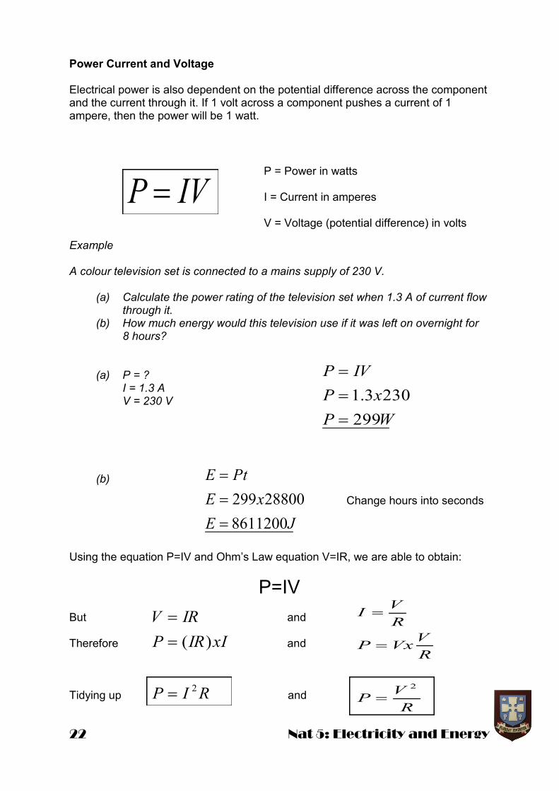
Power Current and Voltage Electrical power is also dependent on the potential difference across the component and the current through it. If 1 volt across a component pushes a current of 1 ampere, then the power will be 1 watt. Example A colour television set is connected to a mains supply of 230 V. (a) Calculate the power rating of the television set when 1.3 A of current flow through it. (b) How much energy would this television use if it was left on overnight for 8 hours? (a) P = ? I = 1.3 A V = 230 V (b) Using the equation P=IV and Ohm’s Law equation V=IR, we are able to obtain:
P=IV
But and Therefore and Tidying up and
IVP
P = Power in watts I = Current in amperes V = Voltage (potential difference) in volts
WP
xP
IVP
299
2303.1
JE
xE
PtE
8611200
28800299
Change hours into seconds
RIP
xIIRP
IRV
2
)(
R
VP
R
VVxP
R
VI
2
Nat 5: Electricity and Energy 23
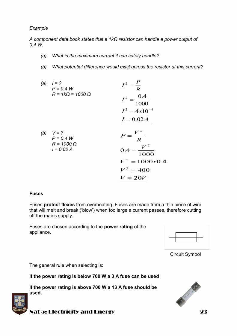
Example A component data book states that a 1kΩ resistor can handle a power output of 0.4 W. (a) What is the maximum current it can safely handle? (b) What potential difference would exist across the resistor at this current? (a) I = ? P = 0.4 W R = 1kΩ = 1000 Ω (b) V = ? P = 0.4 W R = 1000 Ω I = 0.02 A Fuses Fuses protect flexes from overheating. Fuses are made from a thin piece of wire that will melt and break (‘blow’) when too large a current passes, therefore cutting off the mains supply. Fuses are chosen according to the power rating of the appliance. Circuit Symbol The general rule when selecting is: If the power rating is below 700 W a 3 A fuse can be used If the power rating is above 700 W a 13 A fuse should be used.
AI
xI
I
R
PI
02.0
104
1000
4.0
42
2
2
VV
V
xV
V
R
VP
20
400
4.01000
10004.0
2
2
2
2
24 Nat 5: Electricity and Energy
Power Lines Electricity is distributed around the country using a vast network of power lines. These power lines which transmit electricity have a resistance. Therefore the power dissipated can be calculated using: To reduce these power losses the energy providers have investigated and invested in wires with a low resitance. The other way to reduce power losses is to decrease the current flowing through the wires. To do this a high voltage is used. As you know a higher voltages results in a lower current. These measures mean that there is less heat energy lost to the surroundings and therefore more electrical energy transferred to the consumer!
3.5 Heat Heat and Temperature Heat and temperature are related, but they are not the same. Temperature is a measure of the amount of heat energy that a material has. Heat energy is actually a type of kinetic energy. It increases as the movement of the individual particles of the material increases. We state that the temperature of a substance is a measure of the mean kinetic energy of its particles. The temperature of an object will increase as the heat energy increases. Specific Heat Capacity The specific heat capacity of a substance is the amount of heat energy required to change the temperature of 1kg of a substance by 1
oC. Specific heat capacity can be
calculated using the formula: Where: EH is the energy measured in Joules (J) c is the specific heat capacity in Joules per kilogram degrees Celsius (J/kg
oC )
m is the mass in kilograms (kg) ΔT is the change in temperature in degrees Celsius (
oC)
TcmEH
RIP 2
Nat 5: Electricity and Energy 25
Example When a kettle containing 2 kg of water (specific heat capacity 4200 J/kg
oC) cools
from 40 oC to 20
oC, calculate the heat given out by the water.
c = 4200 J/kg
oC
m = 2 kg ΔT = 20
oC
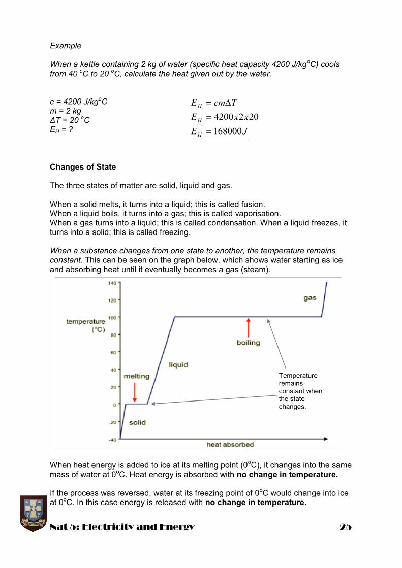
EH = ? Changes of State The three states of matter are solid, liquid and gas. When a solid melts, it turns into a liquid; this is called fusion. When a liquid boils, it turns into a gas; this is called vaporisation. When a gas turns into a liquid; this is called condensation. When a liquid freezes, it turns into a solid; this is called freezing. When a substance changes from one state to another, the temperature remains constant. This can be seen on the graph below, which shows water starting as ice and absorbing heat until it eventually becomes a gas (steam).
When heat energy is added to ice at its melting point (0oC), it changes into the same
mass of water at 0oC. Heat energy is absorbed with no change in temperature.
If the process was reversed, water at its freezing point of 0
oC would change into ice
at 0oC. In this case energy is released with no change in temperature.
JE
xxE
TcmE
H
H
H
168000
2024200
Temperature remains constant when the state changes.
26 Nat 5: Electricity and Energy
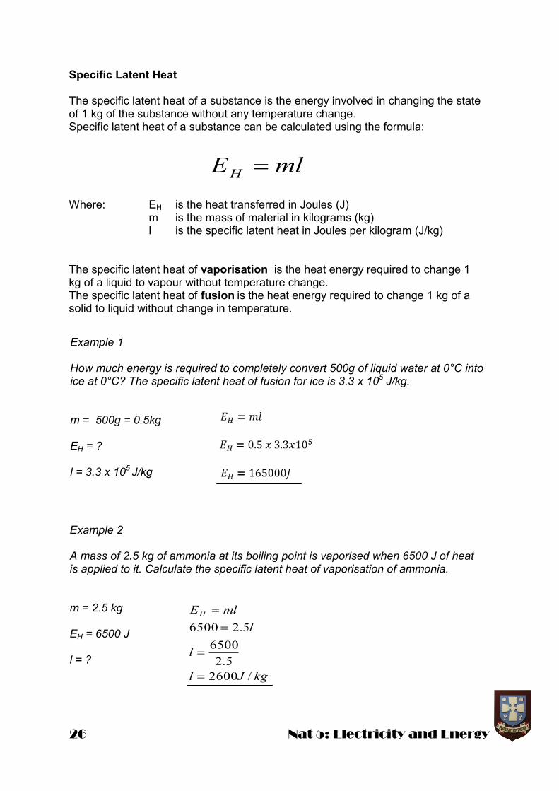
Specific Latent Heat The specific latent heat of a substance is the energy involved in changing the state of 1 kg of the substance without any temperature change. Specific latent heat of a substance can be calculated using the formula: Where: EH is the heat transferred in Joules (J) m is the mass of material in kilograms (kg) l is the specific latent heat in Joules per kilogram (J/kg) The specific latent heat of vaporisation is the heat energy required to change 1 kg of a liquid to vapour without temperature change. The specific latent heat of fusion is the heat energy required to change 1 kg of a solid to liquid without change in temperature.
mlEH
kgJl
l
l
mlEH
/2600
5.2
6500
5.26500
Example 1 How much energy is required to completely convert 500g of liquid water at 0°C into ice at 0°C? The specific latent heat of fusion for ice is 3.3 x 10
5 J/kg.
m = 500g = 0.5kg EH = ? l = 3.3 x 10
5 J/kg
Example 2 A mass of 2.5 kg of ammonia at its boiling point is vaporised when 6500 J of heat is applied to it. Calculate the specific latent heat of vaporisation of ammonia. m = 2.5 kg EH = 6500 J l = ?
Nat 5: Electricity and Energy 27
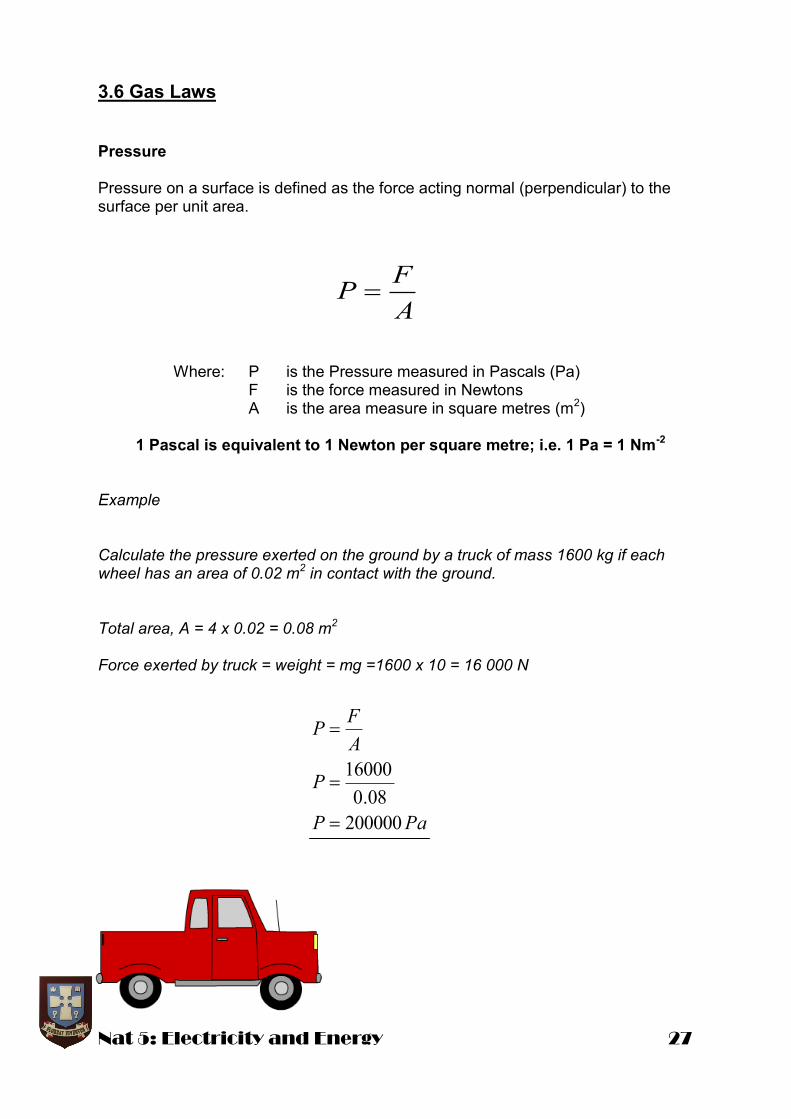
3.6 Gas Laws Pressure Pressure on a surface is defined as the force acting normal (perpendicular) to the surface per unit area. Where: P is the Pressure measured in Pascals (Pa) F is the force measured in Newtons A is the area measure in square metres (m
2)
1 Pascal is equivalent to 1 Newton per square metre; i.e. 1 Pa = 1 Nm
-2
Example Calculate the pressure exerted on the ground by a truck of mass 1600 kg if each wheel has an area of 0.02 m
2 in contact with the ground.
Total area, A = 4 x 0.02 = 0.08 m
2
Force exerted by truck = weight = mg =1600 x 10 = 16 000 N
A
FP
PaP
P
A
FP
200000
08.0
16000
28 Nat 5: Electricity and Energy
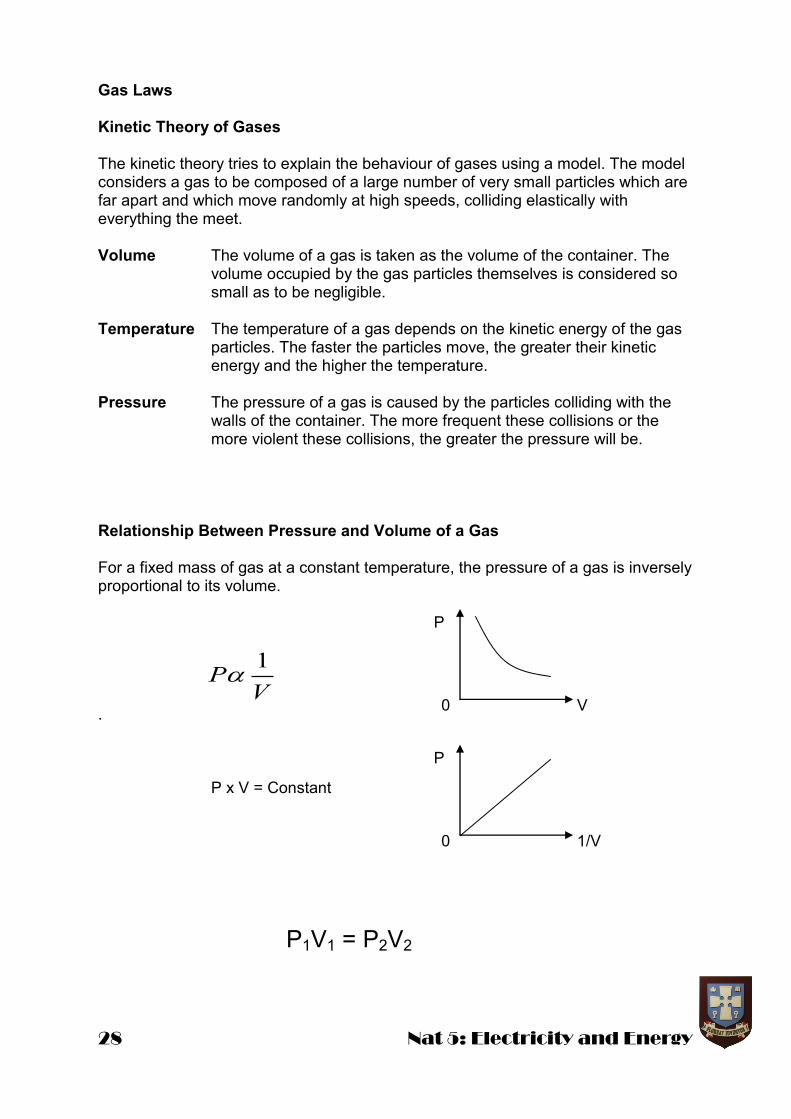
Gas Laws Kinetic Theory of Gases The kinetic theory tries to explain the behaviour of gases using a model. The model considers a gas to be composed of a large number of very small particles which are far apart and which move randomly at high speeds, colliding elastically with everything the meet. Volume The volume of a gas is taken as the volume of the container. The volume occupied by the gas particles themselves is considered so small as to be negligible. Temperature The temperature of a gas depends on the kinetic energy of the gas particles. The faster the particles move, the greater their kinetic energy and the higher the temperature. Pressure The pressure of a gas is caused by the particles colliding with the walls of the container. The more frequent these collisions or the more violent these collisions, the greater the pressure will be. Relationship Between Pressure and Volume of a Gas For a fixed mass of gas at a constant temperature, the pressure of a gas is inversely proportional to its volume. . P x V = Constant
P1V1 = P2V2
VP
1
P
0 V
P
0 1/V

Nat 5: Electricity and Energy 29
Example The pressure of a gas enclosed in a cylinder by a piston changes from 80 kPa to 200 kPa. If there is no change in temperature and the initial volume was 25 litres, calculate the new volume. P1 = 80 kPa P1 V1 = P2 V2 V1 = 25 litres 80 x 25 = 200 x V2 P2 = 200 kPa V2 = 10 litres V2 = ? Relationship Between Pressure and Temperature of a Gas If a graph is drawn of pressure against temperature in degrees Celsius for a fixed mass of gas at a constant volume, the graph is a straight line which does not pass through the origin. When the graph is extended until the pressure reaches zero, it crosses the temperature axis at –273
oC. This is true for all gases.
The Kelvin Temperature Scale –273
oC is called absolute zero and is zero on the Kelvin temperature scale. At a
temperature of absolute zero, 0 K, all particle motion stops and this is therefore the lowest possible temperature. One division on the Kelvin temperature scale is the same size as one division on the Celsius temperature scale, i.e. temperature difference isthe same in Kelvin as in degrees Celsius. Note the unit of the Kelvin scale is the Kelvin, K, not degrees Kelvin!
–273oC T /
oC
P / Pa

30 Nat 5: Electricity and Energy
Converting to Kelvin
If the graph of pressure against temperature is drawn using the Kelvin temperature scale, the graph now goes through the origin. For a fixed mass of gas at a constant volume, the pressure of a gas is directly proportional to its fixed temperature measured in Kelvin (K). Example Hydrogen in a sealed container at 27
oC has a pressure of 1.8 x 10
5 Pa. If it is heat-
ed to a temperature of 77 oC , what will be its new pressure?
P1 = 1.8 x 10
5 Pa
T1 = 27
oC = 300 K
P2 = ? T2 = 77
oC = 350 K
T / K 0
P / Pa
TP constT
P
2
2
1
1
T
P
T
P
PaxP
Px
T
P
T
P
5
2
2
5
2
2
1
1
101.2
350300
108.1
Converting oC into K add 273
Converting K into oC subtract 273

Nat 5: Electricity and Energy 31
Relationship Between Volume and Temperature of a Gas If a graph is drawn of volume against temperature, in degrees Celsius, for a fixed mass of gas at a constant pressure, the graph is a straight line which does not pass through the origin. When the graph is extended until the volume reaches zero, again it crosses the temperature axis at -273
oC. This is true for all gases.
If the graph of volume against temperature is drawn using the Kelvin temperature scale, the graph now goes through the origin. For a fixed mass of gas at a constant pressure, the volume of a gas is directly proportional to its temperature measured in Kelvin (K). Example 400 cm
3 of air is at a temperature of 20
oC. At what temperature will the volume be
500 cm3 if the air pressure does not change?
V1 = 400 cm
3
T1 = 20 oC = 293 K
V2 = 500 cm3
T2 = ?
–273oC T /
oC
V / m3
T / K 0
V / m3
TV constT
V
2
2
1
1
T
V
T
V
KT
T
T
V
T
V
366
500
293
400
2
2
2
2
1
1

32 Nat 5: Electricity and Energy
Combined Gas Equation By combing the previous three relationships, the following relationship for the pressure, volume and temperature of a fixed mass of gas is true for all gases. Example A balloon contains 1.5 m
3 of helium at a pressure of 100 kPa and a temperature of
27 oC. If the pressure is increased to 250 kPa at a temperature of 127
oC, calculate
the new volume of the balloon. P1 = 100 kPa V1 = 1.5 m
3
T1 = 27 oC = 300K
P2 = 250 kPa V2 = ?
T2 = 127 oC = 400K
2
22
1
11
T
VP
T
VPconst
T
VP
3
2
2
22
1
11
8.0
400
250
300
5.1100
mV
xVx
T
VP
T
VP
Nat 5: Electricity and Energy 33
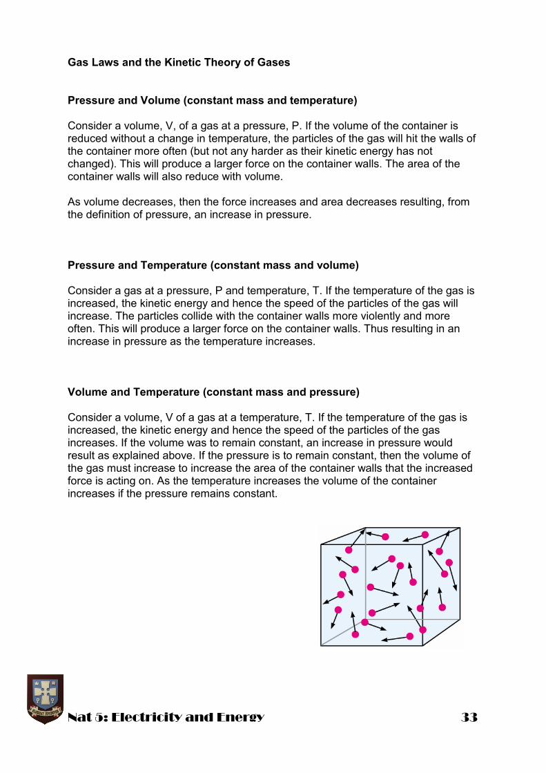
Gas Laws and the Kinetic Theory of Gases Pressure and Volume (constant mass and temperature) Consider a volume, V, of a gas at a pressure, P. If the volume of the container is reduced without a change in temperature, the particles of the gas will hit the walls of the container more often (but not any harder as their kinetic energy has not changed). This will produce a larger force on the container walls. The area of the container walls will also reduce with volume. As volume decreases, then the force increases and area decreases resulting, from the definition of pressure, an increase in pressure. Pressure and Temperature (constant mass and volume) Consider a gas at a pressure, P and temperature, T. If the temperature of the gas is increased, the kinetic energy and hence the speed of the particles of the gas will increase. The particles collide with the container walls more violently and more often. This will produce a larger force on the container walls. Thus resulting in an increase in pressure as the temperature increases. Volume and Temperature (constant mass and pressure) Consider a volume, V of a gas at a temperature, T. If the temperature of the gas is increased, the kinetic energy and hence the speed of the particles of the gas increases. If the volume was to remain constant, an increase in pressure would result as explained above. If the pressure is to remain constant, then the volume of the gas must increase to increase the area of the container walls that the increased force is acting on. As the temperature increases the volume of the container increases if the pressure remains constant.


