NATIONAL BUREAU OF STANDARDS REPORT Test of the Mobilization Structure Under Sustained Uniformly Distributed Load by L. F. Skoda Report to Bureau of Yards and Docks Department of the Navy U. S. DEPARTMENT OF COMMERCE NATIONAL BUREAU OF STANDARDS 7387
Transcript
NATIONAL BUREAU OF STANDARDS REPORT
Test of the Mobilization Structure
Under Sustained Uniformly Distributed Load
by
L. F. Skoda
Report to
Bureau of Yards and Docks
Department of the Navy
U. S. DEPARTMENT OF COMMERCE
NATIONAL BUREAU OF STANDARDS
7387
THE NATIONAL BUREAU OF STANDARDS
Functions and Activities
The functions of the National Bureau of Standards are set forth in the Act of Congress, March 3, 1901, as
amended by Congress in Public Law 619, 1950. These include the development and maintenance of the na-
tional standards of measurement and the provision of means and methods for making measurements consistent
with these standards; the determination of physical constants and properties of materials; the development of
methods and instruments for testing materials, devices, and structures; advisory services to government agen-
cies on scientific and technical problems; invention and development of devices to serve special needs of the
Government; and the development of standard practices, codes, and specifications. The work includes basic
and applied research, development, engineering, instrumentation, testing, evaluation, calibration services,
and various consultation and information services. Research projects are also performed for other government
agencies when the work relates to and supplements the basic program of the Bureau or when the Bureau's
unique competence is required. The scope of activities is suggested by the listing of divisions and sections
on the inside of the back cover.
Publications
The results of the Bureau’s research are published either in the Bureau’s own series of publications or
in the journals of professional and scientific societies. The Bureau itself publishes three periodicals avail-
able from the Government Printing Office: The Journal of Research, published in four separate sections,
presents complete scientific and technical papers; the Technical News Bulletin presents summary and pre-
liminary reports on work in progress; and Basic Radio Propagation Predictions provides data for determining
the best frequencies to use for radio communications throughout the world. There are also five series of non-
A complete listing of the Bureau’s publications can be found in National Bureau of Standards Circular
460, Publications of the National Bureau of Standards, 1901 to June 1947 (SI. 25), and the Supplement to Na-
tional Bureau of Standards Circular 460, July 1947 to June 1957 ($1.50), and Miscellaneous Publication 240,
July 1957 to June 1960 (Includes Titles of Papers Published in Outside Journals 1950 to 1959) (S2. 2 5); avail-
able from the Superintendent of Documents, Government Printing Office, Washington 25, D. C.
NATIONAL BUREAU OF STANDARDS REPORTNBS PROJECT NBS REPORT
1001-12-10411 November 27, 1961 7387
Test of the Mobilization StructureUnder Sustained Uniformly Distributed Load
by
L. F. Skoda
To(
Bureau of Yards and DocksDepartment of the Navy
NATIONAL BUREAU OF STANDintended for use within the Govto additional evaluation and revie
listing of this Report, either in wthe Office of the Director, Nation
however, by the Government ageto reproduce additional copies fo
IMPORTANT NOTICE
'ess accounting documentsApproved for public release by the b published it is subjected
Director of the National Institute of^tion, or open-literature
c . , , , „ , „ is obtained in writing fromStandards and Technology (NIST) h permission is not needed,
on October 9, 2015. >ared If that agency wishes
<NRSy>
U. S. DEPARTMENT OF COMMERCE
NATIONAL BUREAU OF STANDARDS
Test of the Mobilization StructureUnder Sustained Uniformly Distributed Load
L. F. Skoda
A 44- by 80-ft precast thin-shell panel frame structure wasconstructed for the purpose of evaluating erection techniques,structural stability and joint sealing materials. The problemsencountered during erection can be mainly attributed to inade-quate dimensional control of the precast units and handlingtechniques used after casting and during erection of the precastunits; the difficulties during erection of the structure couldhave been avoided by strict adherence to more rigid dimensionalcontrol.
A uniformly distributed live load of 40 psf was applied to
a two bent test section of the structure. A maximum deflectionof 2 in. occurred at mid-span of the roof sections 5 months afterapplication of the test load, as equilibrium was approached. Sidewall movements were significantly large only at the west wall,with a maximum deflection of 0.4 in. evident at equilibrium 3
months after initiation of the test. Daily deflection variationswere observed after equilibrium was reached which can be attri-buted to environmental changes.
The joint sealing materials used in the structure achievedtheir intended purpose but other sources of water penetrationwere apparent. The construction bolts that were exposed to theelements, particularly those used at the wall-roof connections,were a source of leakage. The more damaging source of leakagewas through the transverse cracks that appeared in the webs ofthe roof panels. The exact clause of these cracks has not beenprecisely determined so that a solution to this problem is notapparent at this time.
1. INTRODUCTION
Among the problems confronting the engineer in the design of thin-shell precast concrete structures are. the problems concerning casting and
erection techniques, dimensional tolerances, watertightness of joints, anddeflections under sustained loads. In order to develop the required in-
formation, a 44- by 80-ft experimental "Mobilization Structure" waserected on the NBS grounds at the request of the Bureau of Yards and Docksand a two-bent section of it was subjected to a sustained load test for
a period of a year. This report summarizes the results of the observationsmade on the structure during the past year.
*
2 .
2. PROCEDURE
2.1 Description of Structure.
The "Mobilization Structure" illustrated in figure 1 is a precastthin-shell concrete building composed of 20 bents, each bent being 4-ftwide and spanning 44 ft. The bents are made up of two side wall and tworoof panels that are essentially channel shaped in cross section. Fabri-cation of the building elements and erection of the structure were accom-plished on the basis of a competitive bid contract.
The panels were fastened to one another by a system of bolted and
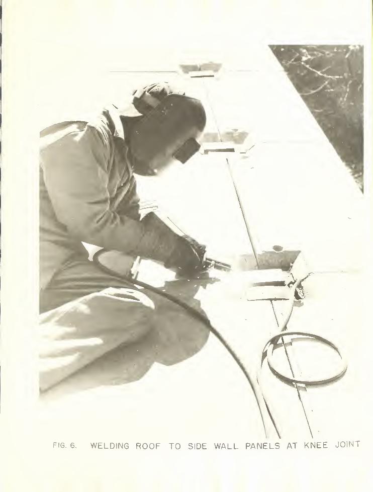
welded connections. Inserts had been cast into the wall panels and foot-ings that enabled a welded connection to be made between each wall paneland the footing. The knee joint (wall-roof connection) was made with lap
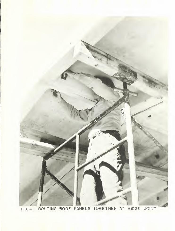
welded splices of metal plates that were attached to the main reinforcingof each wall and roof panel prior to casting. The roof panels comprisingeach bent were joined together at the crown with two 3/4 in. D bolts that
passed through transverse ribs located at the crown ends of the roofpanels. Each bent was connected to the previous bent with a number of
3/4 in. D bolts. These bolts passed through pipe sleeves that were pre-cast into the longitudinal legs of all panels. Closure of the structurewas accomplished with end wall panels that were bolted to the first and
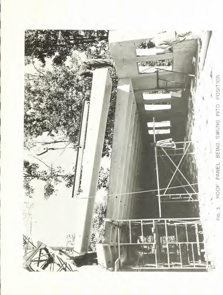
last bents. Views of wall and roof panels, and joints between them are
shown in figures 1 through 6.
2.2 Design of Test
The third and fourth bents from the south end wall were selected as
the two bent test section. These particular bents were chosen becauseerection of the structure began at the north end wall, thereby enablingthe contractor to develop an erection technique prior to erection of thetest bents. The test section was purposely separated from the rest of
the structure by a space of 1/2 in. The two test bents were bolted to-gether but no connections were made to the adjoining bents.
The live load of 20 psf was used in the design of the structure. Auniformly distributed live load equal to twice the design load was appliedto the test section. The test load consisted of pea gravel of known weightcarefully screeded to a predetermined depth. The gravel was maintained at
a uniform depth by a plywood framework that surrounded the test section.The plywood framework was arranged so that the two bents comprising thetest section could be loaded separately.
;
.
3.
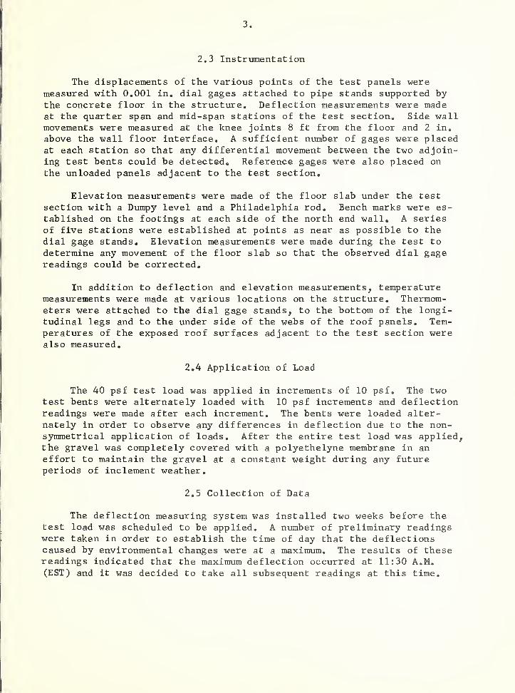
2.3
Instrumentation
The displacements of the various points of the test panels weremeasured with 0.001 in. dial gages attached to pipe stands supported bythe concrete floor in the structure. Deflection measurements were madeat the quarter span and mid-span stations of the test section. Side wallmovements were measured at the knee joints 8 ft from the floor and 2 in.
above the wall floor interface. A sufficient number of gages were placedat each station so that any differential movement between the two adjoin-ing test bents could be detected. Reference gages were also placed on
the unloaded panels adjacent to the test section.
Elevation measurements were made of the floor slab under the testsection with a Dumpy level and a Philadelphia rod. Bench marks were es-
tablished on the footings at each side of the north end wall. A seriesof five stations were established at points as near as possible to thedial gage stands. Elevation measurements were made during the test to
determine any movement of the floor slab so that the observed dial gagereadings could be corrected.
In addition to deflection and elevation measurements, temperaturemeasurements were made at various locations on the structure. Thermom-eters were attached to the dial gage stands, to the bottom of the longi-tudinal legs and to the under side of the webs of the roof panels. Tem-peratures of the exposed roof surfaces adjacent to the test section werealso measured.
2.4
Application of Load
The 40 psf test load was applied in increments of 10 psf. The twotest bents were alternately loaded with 10 psf increments and deflectionreadings were made after each increment. The bents were loaded alter-nately in order to observe any differences in deflection due to the non-symmetrical application of loads. After the entire test load was applied,the gravel was completely covered with a polyethelyne membrane in an
effort to maintain the gravel at a constant weight during any futureperiods of inclement weather.
2.5
Collection of Data
The deflection measuring system was installed two weeks before thetest load was scheduled to be applied. A number of preliminary readingswere taken in order to establish the time of day that the deflectionscaused by environmental changes were at a maximum. The results of thesereadings indicated that the maximum deflection occurred at 11:30 A.M.(EST) and it was decided to take all subsequent readings at this time.
4
At 11:30 A.M. on the day that the test load was applied, a set of zero
readings were taken on all dial gages and elevation stations. The test load
was then applied, as previously described, in 10 psf increments to alternatebents with a complete set of readings being made before and after each incre-
ment. The total load of 40 psf was applied by 2:30 P.M. on the same day at
which time a final set of readings was taken. Subsequent readings were madeon all dial gages according to the following schedule: first 30 days, daily;next 60 days, bi-weekly; next 9 months, bi-monthly; after the first year,monthly.
The reference gages measured movements of the unloaded panels adjacentto the test section. As thefie adjacent panels were bolted to the structurealong one edge only, it was felt that deflection measurements of unloadedpanels that were bolted along both edges would be more significant. Con-sequently, one month after application of the test load, additional gageswere placed at the crown and knee joints of a bent located halfway betweenthe test section and the north end wall.
Five months after the test began the deflection measuring system wasmodified. Mechanical difficulties necessitated the elimination of the
gages measuring the quarter span deflection and the gages measuring wallmovements 2 in. above the floor. The gages at the knee joints and crownwere rearranged to measure average movements at each station rather thanmovements of individual panels. The reference gages at the adjacent panelsand at the middle of the structure were allowed to remain undisturbed.
3. RESULTS
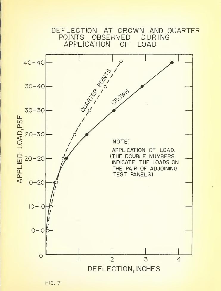
3.1 Instantaneous Deflections During the Loading Period
The differential deflections anticipated as a result of alternate bentloading did not materialize. Figure 7 indicates the deflection vs. appliedload at the crown and quarter points. The applied load notation refers tothe amount of load applied to each bent (i.e., 0-10 means 0 psf on the northbent and 10 psf on the south bent). Although these curves represent theaverage deflection across the profile of each station, the load-deflectioncurves were essentially identical for individual bents.
Side wall movements did not become significant until the entire liveload was applied. Measurements made at the kneee joints (8 ft above thefloor level) indicated an average outward movement of .045 in. at maximumload. Measurements made 2 in, above the floor indicated an average outwardmovement of .002 in. at maximum load.
5.
3.2 Deflections After One Year
Figure 8 is a graphic presentation of the deflection at the crown and
quarter points plotted against the duration of sustained load. The deflec-
tion at the crown increased at a rapid rate for the first 20 days. The
rate of increase became essentially linear for the next 100 days. From the
120 day period until the structure was under test for a year the deflection
at the crown increased at a rate of approximately .01 in. per month, with
a total one year deflection of 2.07 in.
The quarter point deflection measured just after application of the
40 psf load was .23 in. This initial deflection doubled after one day and
increased to .92 in. after 148 days. As previously mentioned, mechanicaldifficulties necessitated the elimination of these gages after 148 days.
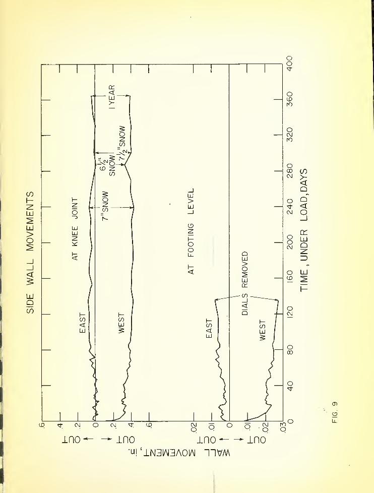
Side wall movements at the knee joints and footings are shown in
figure 9. Very little lateral movement was observed at the knee joint in
the east side wall, the maximum being .08 in. 135 days after the beginningof the test. The west side wall stabilized to an average outward movementof .4 in. approximately 3 months after the beginning of the test. Side
wall movements measured at the footings followed the displacement patternobserved at the knee joints.
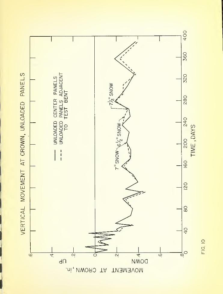
A comparison of movements at the crown of panels adjacent to the testbent and panels near the center of the structure is made in figure 10. Thegages near the center of the structure were placed in service approximatelya month after the test began so that the comparison of deflections couldonly be made from that time on. Movement of the panels adjacent to thetest bents agreed very closely with those observed near the center of thestructure. This agreement indicates that the entire roof section acts as a
unit when subjected to environmental changes.
3.3 Effects of Snow Loads and Temperatures
The deflections observed at times when the structure was subjected tovarious snow loads are indicated on figures 8 through 10. The deflectionobserved during the first snow load of 7 In. shows an expected increase indeflection at the crown accompanied by lateral movement of the side walls.The second snow load of 6.5 in. was preceded by heavy rainfall and a suddenfreeze. This unusual moisture condition in the panels and formation ofice in the open joint between the test bents and the rest of the structureresulted in erratic movements at all gage stations. The third snow load of7.5 in. was preceded by dry weather and the observed deflections conformedto those normally expected. The snow loadings did not appear to produce anylasting effects as deflection recovery occurrred after each thaw.
Temperature measurements were taken at various positions on the struc-ture at the same time as deflection measurements. The difference in tem-perature of the roof surfaces and the underside of the longitudinal legs ofthe panels have been as high as 30° or more. Although an attempt was made
6 .
to correlate these temperatures and temperature differentials with ob-
served deflections, no direct correlation was found to exist between tem-
perature and deflections. It appears that other factors such as changingmoisture conditions of the concrete must be considered.
4.
SUMMARY
1. The instantaneous deflections at maximum load of the crown,
quarter points and knee joints were .380, .236, and .045 in. respectivelywith no differential deflections observed due to alternate bent loading.
2. The equilibrium deflection at the crown was reached 5 months afterapplication of the 40 psf test load and was approximately 2 in.
3. Side wall movements were only significantly large at the west wallwhich attained a maximum stable deflection of 0.4 in. 3 months after ini-
tiation of the test.
4. Deflection measurements taken of unloaded panels at various loca-tions within the structure show that the entire roof system acts as a unitwhen subjected to environmental changes.
5. The effects of snow loading are temporary and full recovery was ob-
served after melting.
6. Daily variations in deflection of precast concrete panels cannot beattributed to temperature alone but must include the moisture condition of
the concrete.
5.
GENERAL OBSERVATIONS
A number of observations were made during and after erection of the
structure that were not directly related to the load test but are of suf-ficient importance to warrant discussion.
5.1 Dimensional Tolerances
It is noted that the firm responsible for casting the panels used inthe Mobilization Structure is a reputable concern with a great deal of
experience in precasting techniques. An inspection of the forms used to
cast the panels revealed that the firm did a commendable job of form con-struction with the personnel involved displaying a great interest in theseparticular panels as well as the future of this type 6f construction. Theforms were constructed of sheet steel and structural shapes that were welded
'
7
together and adequately braced to prevent displacements during casting.With all of the precautions taken to insure accuracy in casting, the
length of the completed structure was 2 in. in excess of the specifiedlength. If the observed departure of 2 in. in 80 ft, or 1 part in 480is considered excessive, it is clear that specifications must be pre-pared which will require a higher degree of dimensional control thanis now available in a commercial plant experienced in precasting opera-tions.
5.2 Erection of Precast Members
Another important point to be considered in the construction of a
building such as the Mobilization Structure is the method used to movethe panels after casting and during erection. The lifting rig devisedto position the roof panels in the structure consisted of a stiff backthat was bolted to the panels by means of four threaded inserts that
had been cast into each panel. The side walls were positioned in a
similar fashion with a stiff back bolted to the top of each panel by
means of two threaded inserts. Figures 2 and 3 show panels beingpositioned with a crane.
This system of moving the panels proved successful in that no panelswere lost through breakage or severe damage. However, two objection-able features resulted from the use of this system. Cracks developedacross the webs of each roof panel between opposite pairs of inserts.These cracks indicate that a plane of weakness was created by the insertcavities. After erection of the building was completed the insert cavi-ties were filled with dry grout. These grout plugs appeared sound priorto the winter season, but after a number of cycles of freezing and thaw-ing the bond between the panels and the plugs was destroyed to such anextent that the plugs could be simply lifted out of the cavities. Theseresults indicate that the panels must be adequately reinforced in thevicinity of the embedded inserts, and that greater care must be takenin grouting the insert cavities. In the future, the insert cavitieswill receive a coating of epoxy/Thiokol adhesive prior to grouting, a
system which proved to be successful in grouting welded joints of precastconcrete panels - (See NBS Report 6682).
5.3 Bolted Connections
The third point to be considered in this discussion deals with thesystem of bolts used between bents. The first indication of an existingproblem was realized on the morning of the second day of erection. Thefirst three bents had been erected on the first day with all bolts in
place and only hand tightened. The following morning an inspection ofthe three bent section revealed visible cracks between the vertical ribsand the webs of the side wall panels. Further investigation revealed
.
8
that the bolts were so tight that they could not be easily loosened with a
wrench. The conclusion reached was that the tightening of the bolts re-
sulted from the temperature drop that occurred between 4:00 P.M. of thefirst day and 8:00 A.M. of the second day. With this experience in mindthe erectors installed all subsequent bolts in the wall panels with a veryminimum of tightening.
Another problem brought about by the use of the bolt system is that
each bolt exposed to weathering is a source of water leakage during rainyweather. The bolts at the knee joints in particular exhibited a tendencyto permit the passage of water. The reason for this is that water runningoff the roof follows the contour of the upper wall section and passesthrough the bolt holes. The same problem is evident at the bolted connec-tions between wall panels but with less severity than was observed at the
knee joints. The elimination of exposed bolts would, of course, be theideal solution to the problem and future design considerations should bedirected towards this end.
5.4 Cracks in Webs of Roof Panels
It was observed a number of months after erection of the structurethat the webs of all roof panels exhibited transverse cracks spaced approxi-mately 2 ft apart along their lengths. These cracks were large enough toproduce visible damp spots on the under side of the panels during any rainstorm. When a continuous light rain or a sudden heavy rain storm occurredsufficient water leaked through the cracks to completely wet the floor area.
The first explanation advanced for these cracks was that they occurredas a result of drying shrinkage. An investigation was undertaken to producesimilar cracking in scaled down laboratory size specimens similar to theroof panels. Although this investigation is not complete, indications arethat shrinkage alone does not account for the formation of transverse andlongitudinal cracks in the webs. The present hypothesis is that thesecracks were caused by a combination of drying shrinkage and thermal stressesresulting from temperature differentials between the longitudinal legs and
webs of the panels.
USCOMM-NBS-DC
FIG.
I.
MOBILIZATION
STRUCTURE
FIG.
3.
ROOF
PANEL
BEING
SWUNG
INTO
POSITION
FIG. 4. BOLTING ROOF PANELS TOGETHER AT RIDGE JOINT
FIG.
5.
BOLTING
ROOF
TO
SIDE
WALL
PANELS
AT
KNEE
JOIN!
APPLIED
LOAD,PSF
DEFLECTION AT CROWN AND QUARTERPOINTS OBSERVED DURINGAPPLICATION OF LOAD
DEFLECTION
AT
CROWN
AND
QUARTER
POINTS
UNDER
SUSTAINED
UNIFORMLY
DISTRIBUTED
LOAD
OF
40
PSF
I
IS
'U!£
NOI103~ld3CI
00
S2u_
120
160
200
240
280
320
360
400
TIME,
UNDER
LOAD
,
DAYS
SIDE
WALL
MOVEMENTS
mo-—-±no ino— — ino'U| ‘1N31AJ3A01AI TIVM
120
160
200
240
280
320
360
400
TIME,
UNDER
LOAD,
DAYS
VERTICAL
MOVEMENT
AT
CROWN,
UNLOADED
PANELS
dn NMoa'
u!
‘ NMOidO IV -LN31AI3A01AI
120
160
200
240
280
320
360
400
TIME
,
DAYS
U. S. DEPARTMENT OE COMMERCELuther H. Hodges, beaetury
NATIONAL BUREAU OF STANDARDSA. V. Astin, Director
THE NATIONAL BUREAU OF STANDARDS
The scope of activities of the National Bureau of Standards at its major laboratories in Washington, D.C., and
Boulder, Colorado, is suggested in the following listing of the divisions and sections engaged in technical work.
In general, each section carries out specialized research, development, and engineering in the field indicated by
its title. A brief description of the activities, and of the resultant publications, appears on the inside of the
front cover.
WASHINGTON, D.C.
Electricity. Resistance and Reactance. Electrochemistry. Electrical Instruments. Magnetic Measurements.Dielectrics. •
Metrology. Photometry and Colorimetry. Refractometry. Photographic Research. Length. Engineering Metrology.Mass and Scale. Volumetry and Densimetry.
Heat. Temperature Physics. Heat Measurements. Cryogenic Physics. Equation of State. Statistical Physics.
Radiation Physics. X-ray. Radioactivity. Radiation Theory. High Energy Radiation. Radiological Equipment.Nucleonic Instrumentation. Neutron Physics.
Analytical and Inorganic Chemistry. Pure Substances. Spectrochemistry. Solution Chemistry. Standard Refer-
Building Research. Structural Engineering. Fire Research. Mechanical Systems. Organic Building Materials.Codes and Safety Standards. Heat Transfer. Inorganic Building Materials.
Ionosphere Research and Propagation. Low Frequency and Very Low Frequency Research. Ionosphere Research.Prediction Services. Sun-Earth Relationships. Field Engineering. Radio Warning Services.
Radio Propagation Engineering. Data Reduction Instrumentation. Radio Noise. Tropospheric Measurements.Tropospheric Analysis. Propagation-Terrain Effects. Radio-Meteorology. Lower Atmosphere Physics.Radio Standards. High Frequency Electrical Standards. Radio Broadcast Service. Radio and Microwave Materi-als. Atomic Frequency ana Time Interval Standards. Electronic Calibration Center. Millimeter-Wave Research.Microwave Circuit Standards.
Radio Systems. High Frequency and Very High Frequency Research. Modulation Research. Antenna Research.Navigation Systems.
Upper Atmosphere and Space Physics. Upper Atmosphere and Plasma Physics. Ionosphere and ExosphereScatter. Airglow and Aurora. Ionospheric Radio Astronomy.