N early all surfaces reflect light. Some surfaces, such as the surface of this lake, reflect light in a way that creates an almost perfect image of the surroundings. People often refer to such a lake as a “glassy lake” because the surface is so smooth and still, like glass. Water must be very smooth and still in order to reflect light in a way that produces an image. However, the pages of this book are smooth and still but you cannot see a reflection of your face when you look at the pages. What is the difference between the surface of still water or of a mirror and the surface of these pages in the way that they reflect light? In this chapter, you will learn about the law of reflection and how to use the law to make predictions about whether an image will form and how it will appear. 170
Transcript
Nearly all surfaces reflect light. Some surfaces, such as the surface of this lake, reflect light in a way that creates an almost perfect image
of the surroundings. People often refer to such a lake as a “glassy lake” because the surface is so smooth and still, like glass. Water must be very smooth and still in order to reflect light in a way that produces an image. However, the pages of this book are smooth and still but you cannot see a reflection of your face when you look at the pages. What is the difference between the surface of still water or of a mirror and the surface of these pages in the way that they reflect light? In this chapter, you will learn about the law of reflection and how to use the law to make predictions about whether an image will form and how it will appear.
Sir Isaac Newton believed that light is a stream of fast-moving, unimaginably tiny particles. For example, a lantern flame was thought to release tiny particles of light, which travelled in a perfectly straight line until they entered an eye, where they were absorbed to make an image. This model came to be called the particle model of light, and parts of the model are still in use today.
However, light also has properties that are best described using waves, such as the use of wavelength and frequency to account for the different colours of light. You studied the wave model of light in Chapter 4. The particle model and the wave model correctly describe some properties of light, but neither one describes all of light’s properties.
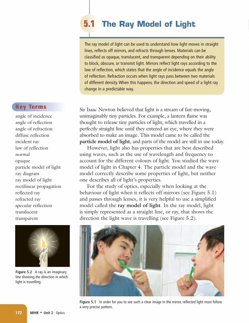
For the study of optics, especially when looking at the behaviour of light when it reflects off mirrors (see Figure 5.1) and passes through lenses, it is very helpful to use a simplified model called the ray model of light. In the ray model, light is simply represented as a straight line, or ray, that shows the direction the light wave is travelling (see Figure 5.2).
Key Termsangle of incidenceangle of reflectionangle of refractiondiffuse reflectionincident raylaw of reflectionnormalopaqueparticle model of lightray diagramray model of lightrectilinear propagationreflected rayrefracted rayspecular reflectiontranslucenttransparent
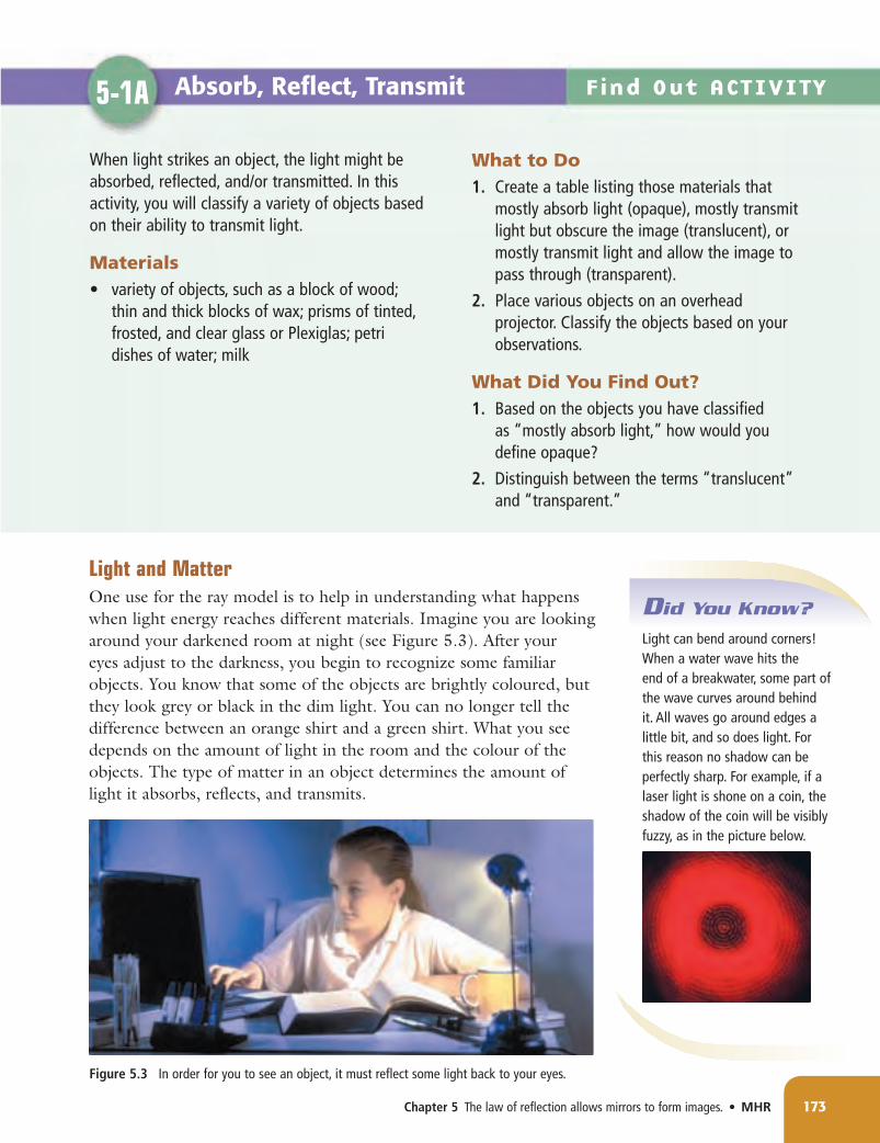
Light and MatterOne use for the ray model is to help in understanding what happens when light energy reaches different materials. Imagine you are looking around your darkened room at night (see Figure 5.3). After your eyes adjust to the darkness, you begin to recognize some familiar objects. You know that some of the objects are brightly coloured, but they look grey or black in the dim light. You can no longer tell the difference between an orange shirt and a green shirt. What you see depends on the amount of light in the room and the colour of the objects. The type of matter in an object determines the amount of light it absorbs, reflects, and transmits.
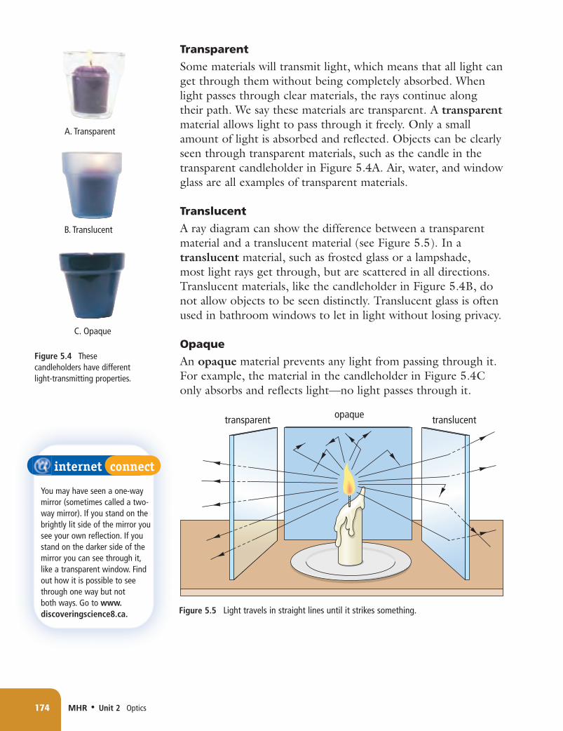
Some materials will transmit light, which means that all light can get through them without being completely absorbed. When light passes through clear materials, the rays continue along their path. We say these materials are transparent. A transparent material allows light to pass through it freely. Only a small amount of light is absorbed and reflected. Objects can be clearly seen through transparent materials, such as the candle in the transparent candleholder in Figure 5.4A. Air, water, and window glass are all examples of transparent materials.
Translucent
A ray diagram can show the difference between a transparent material and a translucent material (see Figure 5.5). In a translucent material, such as frosted glass or a lampshade, most light rays get through, but are scattered in all directions. Translucent materials, like the candleholder in Figure 5.4B, do not allow objects to be seen distinctly. Translucent glass is often used in bathroom windows to let in light without losing privacy.
Opaque
An opaque material prevents any light from passing through it. For example, the material in the candleholder in Figure 5.4C only absorbs and reflects light—no light passes through it.
ShadowsShadows tell you about one of the most important properties of light: light travels in straight lines. This is known as rectilinear propagation. It is true as long as light stays in the same medium, or substance. This property allows you to make predictions about shadows and images using ray diagrams. For example, when you are walking away from the Sun during sunset, your shadow becomes much longer than you are tall (see Figure 5.6). In the ray diagram, your body casts a shadow because it blocks the light rays striking you. The light rays on either side of you continue in a straight line until they hit the ground. Figure 5.7 shows how a ray diagram can be used to show how the size of shadows is related to the distance of the object from the light source.
Reading Check1. What are three uses for the ray model?2. How is an opaque material different from a translucent
material?3. Is a glass of water with red food colouring in it translucent
or transparent? Explain.4. What is the relationship between the size of the shadow and
the distance of the object from the light source?
NL8 U2 CH05.indd 175 11/5/08 1:18:50 PM
Light Can Be ReflectedThis book uses black letters printed on white paper. The black ink is opaque because all the light falling on the ink is absorbed. But the white paper reflects all of the light that falls on it. Does that mean the white paper is a mirror? If so, why can you not see your reflection in the white parts of the page?
In fact, there are two different types of reflection. Reflection from a mirror-like surface, which produces an image of the surroundings, is called specular reflection. Reflection from a rough surface, which does not produce a clear image but instead allows you to see what is on the surface, is called diffuse reflection. To act as a mirror, a surface needs to be smooth compared to the wavelength of the light striking the surface (see Figure 5.8A). Even though a piece of paper may feel smooth, a photograph taken through a microscope reveals that the surface is actually not very smooth at all (see Figure 5.8B). The ray diagram shows that the light rays bounce off randomly at all angles, giving the paper the appearance of being translucent (see Figure 5.8C).
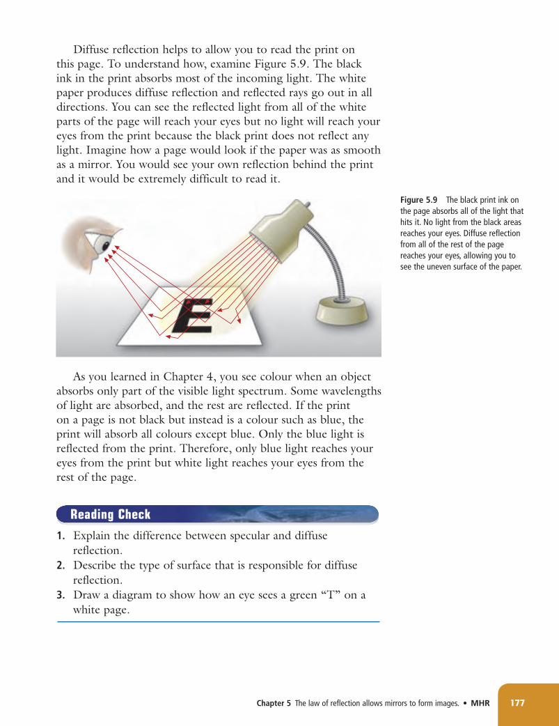
Diffuse reflection helps to allow you to read the print on this page. To understand how, examine Figure 5.9. The black ink in the print absorbs most of the incoming light. The white paper produces diffuse reflection and reflected rays go out in all directions. You can see the reflected light from all of the white parts of the page will reach your eyes but no light will reach your eyes from the print because the black print does not reflect any light. Imagine how a page would look if the paper was as smooth as a mirror. You would see your own reflection behind the print and it would be extremely difficult to read it.
As you learned in Chapter 4, you see colour when an object absorbs only part of the visible light spectrum. Some wavelengths of light are absorbed, and the rest are reflected. If the print on a page is not black but instead is a colour such as blue, the print will absorb all colours except blue. Only the blue light is reflected from the print. Therefore, only blue light reaches your eyes from the print but white light reaches your eyes from the rest of the page.
Reading Check1. Explain the difference between specular and diffuse
reflection.2. Describe the type of surface that is responsible for diffuse
reflection.3. Draw a diagram to show how an eye sees a green “T” on a
white page.
NL8 U2 CH05.indd 177 11/5/08 1:18:54 PM
The Law of ReflectionHow does light reflect off a mirror? It is helpful to think about how a light ray is similar to a water wave bouncing off a solid barrier. Imagine a great rock wall rising high out of the water. If waves strike such a barrier head on, the waves will bounce straight back in the reverse direction. However, if a wave strikes the barrier from an angle, then it will also bounce off at an angle—at precisely the same angle as the incoming wave that struck the barrier.
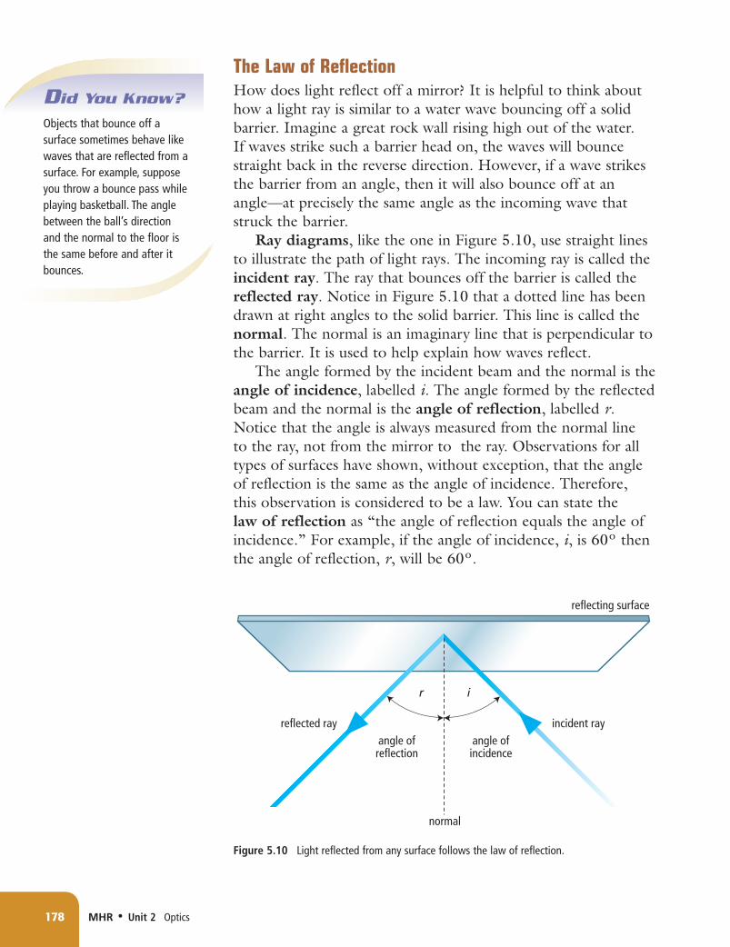
Ray diagrams, like the one in Figure 5.10, use straight lines to illustrate the path of light rays. The incoming ray is called the incident ray. The ray that bounces off the barrier is called the reflected ray. Notice in Figure 5.10 that a dotted line has been drawn at right angles to the solid barrier. This line is called the normal. The normal is an imaginary line that is perpendicular to the barrier. It is used to help explain how waves reflect.
The angle formed by the incident beam and the normal is the angle of incidence, labelled i. The angle formed by the reflected beam and the normal is the angle of reflection, labelled r. Notice that the angle is always measured from the normal line to the ray, not from the mirror to the ray. Observations for all types of surfaces have shown, without exception, that the angle of reflection is the same as the angle of incidence. Therefore, this observation is considered to be a law. You can state the law of reflection as “the angle of reflection equals the angle of incidence.” For example, if the angle of incidence, i, is 60º then the angle of reflection, r, will be 60º.
Light Can Be RefractedYou learned in Chapter 4 that refraction is the bending of a wave, such as light, when it travels from one medium (material) to another. Figure 5.11 shows you how light bends as it travels from air to water.
Waves bend because the speed of the waves changes when travelling from one medium to another. But why does a change in speed cause a change in the direction of a wave?
To visualize what happens when the crest of a wave reaches the surface between two media, imagine each wave crest as a row of students in a marching band. In Figure 5.12, you see the band marching from an area of firm ground to an area of mud. The mud is so sticky that the students cannot march as fast. As each student in the band reaches the mud, he or she slows down. The slower students “pull” the line back and cause a bend in the line. As a result, the direction in which the entire row is marching, changes. The larger red arrow shows the direction in which the band, as a whole, is moving. This is just what happens to a wave when it crosses the surface from air into water.
Describing Refraction Now that you understand why a change in the speed of a wave, such as light, causes refraction, you can use rays to describe the direction of the wave. Most of the terms used to describe refraction are the same or similar to the terms used with reflection (Figure 5.13). The incident ray and angle of incidence are defined just as they are in reflection. This time, the normal is perpendicular to the surface between the two media and it extends through both media. As you can see in the figure, the refracted ray is in the second medium and is travelling in a different direction than the incident ray. The angle labelled “R” is the angle of refraction. Note that a capital, or uppercase, R is used for refraction whereas a small, or lowercase, r is used for reflection.
The Direction of the Refracted Ray You saw in the model of the marching band that when the marchers slowed down, their direction turned toward the normal. In general, when the speed of a wave slows down in the second medium, the direction of the wave is bent toward the normal. Is there a way that you can predict whether a wave will slow down or speed up when going from the first to the second medium?
The density of the material determines the speed of light in that medium. In general, light travels more slowly in a more dense medium than in a less dense medium. Therefore, when light travels from a less dense to a more dense medium, the ray bends toward the normal. When light travels from a more dense medium to a less dense medium, the ray bends away from the normal. These points are summarized in Figure 5.14.
Refraction Effects When you see an object, your brain assumes that the light coming from the object traveled to your eyes in straight lines. However, if the light from the object passed through two different media before it reached your eye, the light did not travel in a straight line. As a result, the object is not where your brain thinks it is.
Reading Check1. What is the relationship between the crest of a wave and the
direction of the wave?2. Why does the direction of a ray of light change when the
light travels from one medium to another medium having a different density?
3. Define “angle of refraction.”
less densemore dense
R
imore denseless dense
R
i
Figure 5.14Thedirectioninwhicharefractedraytravelsdependsonwhetherthesecondmediumismoredenseorlessdensethanthefirstmedium.InA,thelightisslowingdownasitentersthedensermedium,justasthemarchingbandisslowingdownastheymarchintothemud.InB,thelightisspeedingupasitexitsthedensermedium,justasthemarchersarespeedingupastheymarchoutofthemud.A B
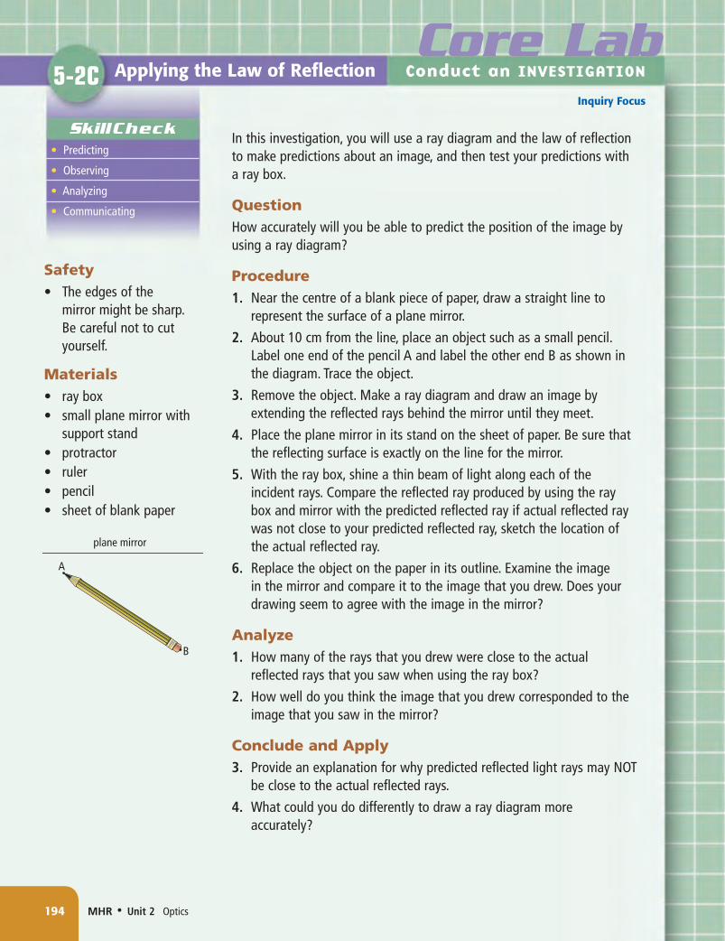
Investigation5-1Donpage184.
Suggested Activity
NL8 U2 CH05.indd 181 11/5/08 1:19:03 PM
You can see this effect if you look at a pencil that is sticking out of a glass of water (Figure 5.15). The light from the top portion of the pencil travels in a straight line to your eye. The light from the bottom portion bends as it exits the water. Your brain has trouble determining the correct position of the underwater portion, so the pencil appears to be broken at the water level.
To understand how your brain sees an underwater object, examine Figure 5.16. The solid line from the fish shows the actual path of the light. It bends at the surface of the water before reaching your eye. The dotted line shows how your brain thinks the light is travelling. Your brain thinks that the fish is located at the “apparent position.”
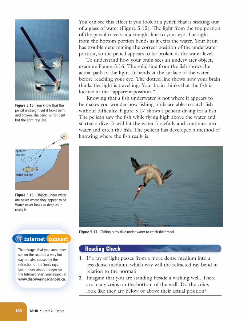
Knowing that a fish underwater is not where it appears to be makes you wonder how fishing birds are able to catch fish without difficulty. Figure 5.17 shows a pelican diving for a fish. The pelican saw the fish while flying high above the water and started a dive. It will hit the water forcefully and continue into water and catch the fish. The pelican has developed a method of knowing where the fish really is.
Reading Check1. If a ray of light passes from a more dense medium into a
less dense medium, which way will the refracted ray bend in relation to the normal?
2. Imagine that you are standing beside a wishing well. There are many coins on the bottom of the well. Do the coins look like they are below or above their actual position?
A Light slows down and refracts toward the normal as it passes from air into water.
B Light speeds up and bends away from the normal as it passes from water into air.
normal
water
air
normal
NL8 U2 CH05.indd 185 11/5/08 1:19:22 PM
186 MHR • Unit 2 Optics
How Big Is Earth?WhatisthecircumferenceofEarth?TodayyoumightusetheInternettofindtheanswer.But2250yearsago,youcouldhaveaskedamannamedEratosthenesofAlexandria,Egypt.Hehadjustfigureditoutforhimself,andwasthefirstpersontodoso.Eratostheneswasamathematician,ageographer,andthedirectorofthegreatlibraryofAlexandria,thegreatestcentreofknowl-edgeoftheancientworld.
Checking Concepts1. Compare and contrast the following
terms: (a) translucent, transparent (b) transmit, absorb (c) reflect, refract2. The angle of incidence of a light ray is
43°. What is the angle of reflection?3. Light slows down as it moves from air
into water. Explain how this causes the direction of a light ray to change.
4. Why can you see your reflection in a smooth piece of aluminum foil, but not in a crumpled ball of foil?
5. If you look at a shiny object and see your reflection in it, are you experiencing specular reflection or diffuse reflection? Explain.
Understanding Key Ideas6. Explain how shadows demonstrate
rectilinear propagation.7. (a) What is meant by the term “normal”
in a ray diagram that represents reflection?
(b) Does the meaning of normal change when representing refraction? Explain.
8. Why does a pencil that is sticking out of a glass of water look bent? Draw a diagram to support your explanation.
9. (a) Draw a line representing a flat mirror. Then add a normal line perpendicular to the mirror. Draw a light ray approaching and then touching the mirror at the same place as the normal line. Complete the ray diagram showing the ray’s reflection.
(b) Label the incident ray, normal, reflected ray, angle of incidence, and angle of reflection.
10. A semi-transparent mirror will both reflect and refract an incident light ray. Draw a straight line representing the surface of a glass mirror. Show a light ray striking the surface of the mirror at a slightly downward angle. The ray splits into a reflected ray, which bounces back, and a refracted ray, which is transmitted through the glass. When drawing your sketch, make sure to use the laws of reflection. The refracted ray will bend toward the normal since glass is denser than air.
11. Why is it desirable that the pages of a book be rough rather than smooth and glossy?
You can see your reflection as you glance into a calm pool of water or walk past a shop window. When you "see yourself", in a reflection, you are actually seeing a likeness of yourself called an image. Most of the time, you probably look for your image in a flat, smooth mirror called a plane mirror.
Plane MirrorsHow do reflected rays form an image that we can see in a mirror?
Study Figure 5.18 to answer this question. When light shines on an object such as a blueberry, the light reflects off all points on the blueberry in all directions. In Figure 5.18, just a few of the rays that reflect off one point on the blueberry are shown. All of the rays from the blueberry that strike the mirror reflect according to the law of reflection. The rays that reach your eye appear to be coming from a point behind the mirror. The same process occurs for every point on the blueberry. The brain is trained to assume that light rays travel in straight lines. Therefore, your brain interprets the pattern of light that reaches your eye as an image of a blueberry behind the mirror. To find out where the brain believes the blueberry to be, extend the rays that reach the person's eye backward to a point behind the mirror. These extended rays are shown by the dotted lines in the figure. When you extend more than one ray, the lines will meet at a point behind the mirror. This is the point where the image is located. You could carry out the same process for several points on the blueberry to find out exactly where the entire image of the blueberry is located.
The image of the blueberry is called a virtual image, since the light rays that reach the eye only appear to be coming from the object. The reflected rays don't actually meet; only the extended rays meet at the object. When an object's image lies behind the mirror, the image is virtual.
Predicting Image CharacteristicsWe can use mirrors for many applications if we know certain things about the images they produce. In fact, we can predict certain characteristics of an image by asking four questions:How does the image size compare to the object size?How does the image distance compare to the object distance?Is the image upright (right-side-up) or inverted (upside-down)?Is the image virtual?
If you measure the length of an object and its image in a plane mirror, you will find that they are the same size. Next, measure the distance from the object to the mirror. This is called the object distance. Then, measure the distance from the image to the mirror. (You can do this by placing a ruler between the object and the mirror.) This is called the image distance. You will find that an image in a plane mirror is the same distance from the mirror as is the object. Next, note that an image in a plane mirror is the same orientation as the object. If the object is upright, the image is also upright. Finally, note that the image is behind the mirror. No light rays actually meet at the image, so the image must be virtual.The following points summarize the characteristics of images in plane mirrors:• Image size is equal to object size.• Image distance is equal to object distance.• The image is upright. (Its orientation is the same as that of
the object.)• The image is virtual.
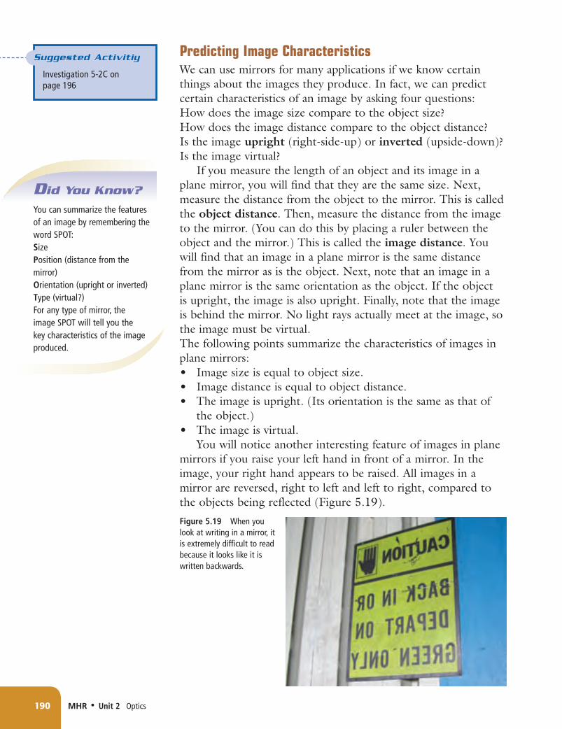
You will notice another interesting feature of images in plane mirrors if you raise your left hand in front of a mirror. In the image, your right hand appears to be raised. All images in a mirror are reversed, right to left and left to right, compared to the objects being reflected (Figure 5.19).
Using Plane Mirrors When you think of plane mirrors, you probably think first of a bathroom mirror which you might often use to comb your hair. Figure 5.20 shows many different uses for plane mirrors.
Reading Check1. Why does your brain see an image behind a plane mirror?2. What is a virtual image?3. How would you describe an image in a plane mirror?
Checking Concepts1. When you view an object in a plane
mirror, light rays carry an image to your eye.
a) Where do the light rays appear to be coming from?
b) Where are the light rays actually coming from?
2. Draw a ray diagram of an object in a plane mirror and use the law of reflection to predict the image. Draw and label the normal. Measure and label the angles of incidence and reflection.
3. How is the image produced by a plane mirror different from the object it reflects?
4. List the relationships between an object and its image as seen in a plane mirror.
5. Give at least three examples of uses for plane mirrors.
Understanding Key Ideas6. The following diagram represents a pool
table with a billiard ball sitting on it. When a billiard ball hits the side of the table, it bounces off according to the law of reflection. Copy the drawing on a piece of paper. Sketch the path that the ball would have to take in order to bounce off the opposite side of the table and then land in pocket A. Sketch the path that the ball would have to take in order to bounce off the opposite side of the table and then land in pocket B. Hint: If the side of the table where the ball hits is like a mirror, where is the
image of the pocket you want the ball to go in? Why might you aim at that image?
7. If you can see another person’s face in a mirror, what must that person see in the same mirror? Explain.
In Section 5.21, you learned that, in plane mirrors, the distance from the mirror to the image is equal to the distance from the mirror to the object. The warning that appears on the mirror in Figure 5.21 suggests that this is not true for curved mirrors. How does a curved mirror change the image? How can you predict the properties of images in mirrors such as this one? In this section, you will learn how to describe and predict the formation of images in curved mirrors.
Concave Mirrors Have you ever looked at yourself in
a shaving mirror or a makeup mirror? If you held the mirror close to your face, you probably noticed that the image of your face was very large. If you looked at the mirror from a distance, though, you would have seen that the image of your face looked very small—and upside-down! How could one mirror produce such different images?
Shaving and makeup mirrors are examples of concave mirrors. Concave mirrors have a reflecting surface that curves inward like the inside of a bowl or sphere. The curved surface of the mirror reflects light in a unique way, creating an image that differs from the object being reflected (Figure 5.22).
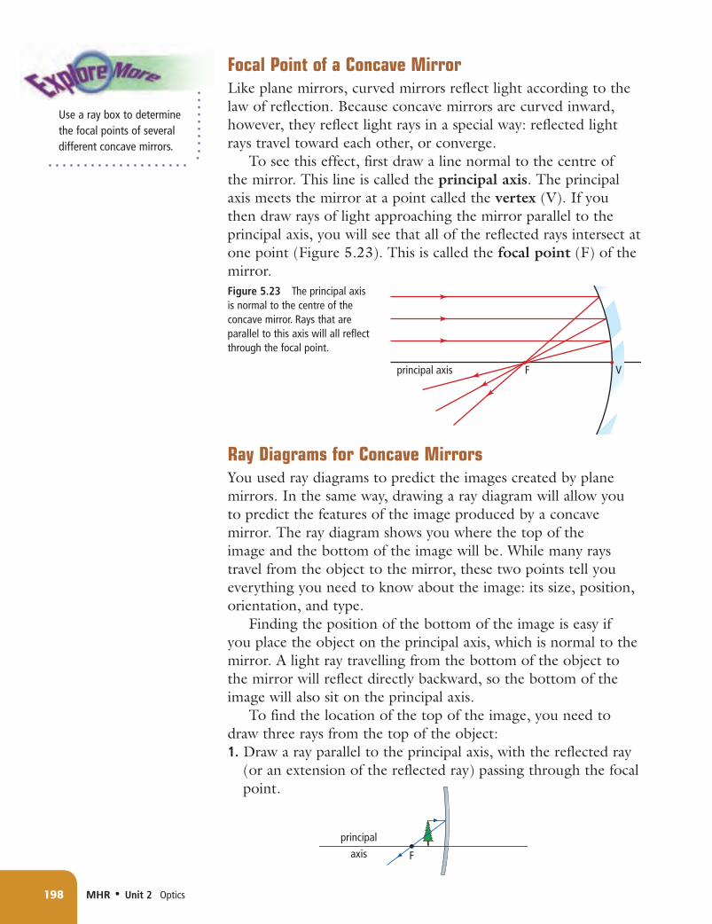
Focal Point of a Concave MirrorLike plane mirrors, curved mirrors reflect light according to the law of reflection. Because concave mirrors are curved inward, however, they reflect light rays in a special way: reflected light rays travel toward each other, or converge.
To see this effect, first draw a line normal to the centre of the mirror. This line is called the principal axis. The principal axis meets the mirror at a point called the vertex (V). If you then draw rays of light approaching the mirror parallel to the principal axis, you will see that all of the reflected rays intersect at one point (Figure 5.23). This is called the focal point (F) of the mirror.
Ray Diagrams for Concave Mirrors You used ray diagrams to predict the images created by plane mirrors. In the same way, drawing a ray diagram will allow you to predict the features of the image produced by a concave mirror. The ray diagram shows you where the top of the image and the bottom of the image will be. While many rays travel from the object to the mirror, these two points tell you everything you need to know about the image: its size, position, orientation, and type.
Finding the position of the bottom of the image is easy if you place the object on the principal axis, which is normal to the mirror. A light ray travelling from the bottom of the object to the mirror will reflect directly backward, so the bottom of the image will also sit on the principal axis.
To find the location of the top of the image, you need to draw three rays from the top of the object:1. Draw a ray parallel to the principal axis, with the reflected ray
(or an extension of the reflected ray) passing through the focal point.
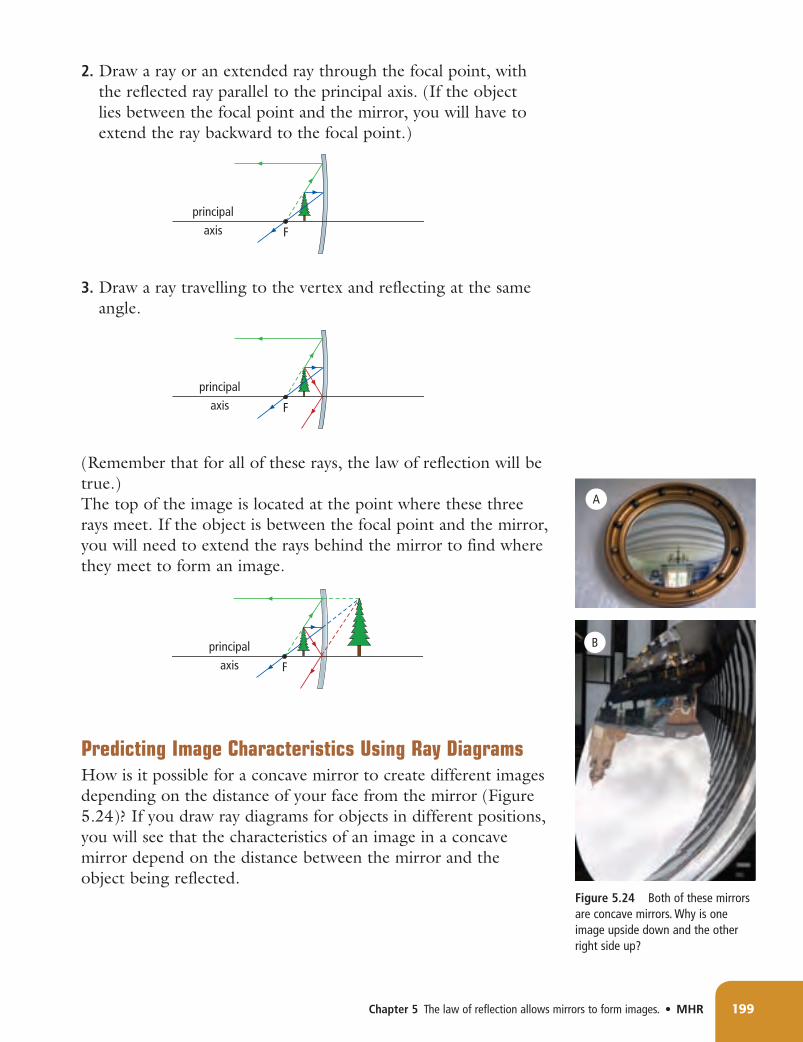
2. Draw a ray or an extended ray through the focal point, with the reflected ray parallel to the principal axis. (If the object lies between the focal point and the mirror, you will have to extend the ray backward to the focal point.)
3. Draw a ray travelling to the vertex and reflecting at the same angle.
(Remember that for all of these rays, the law of reflection will be true.)The top of the image is located at the point where these three rays meet. If the object is between the focal point and the mirror, you will need to extend the rays behind the mirror to find where they meet to form an image.
Predicting Image Characteristics Using Ray DiagramsHow is it possible for a concave mirror to create different images depending on the distance of your face from the mirror (Figure 5.24)? If you draw ray diagrams for objects in different positions, you will see that the characteristics of an image in a concave mirror depend on the distance between the mirror and the object being reflected.
Recall that if you hold a makeup mirror very close to your face, your image will appear very large (Figure 5.25). By drawing the three rays from the top of the object, you can predict the image. Look at the ray diagram in Figure 5.26 to see how this image is produced.
For a concave mirror, when an object is between the focal point and the mirror, the image has the following characteristics:• The image is larger than the object.• The image distance is larger than the object distance.• The image is upright.• The image is virtual.
Object Between the Focal Point and Two Times the Focal Point
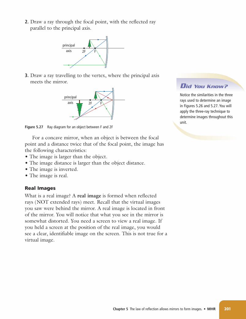
As you move a makeup mirror away from your face, your image will become inverted. Draw the three rays from the top of the object to find out why:
1. Draw a ray parallel to the principal axis, with the reflected ray passing through the focal point.
2. Draw a ray through the focal point, with the reflected ray parallel to the principal axis.
3. Draw a ray travelling to the vertex, where the principal axis meets the mirror.
For a concave mirror, when an object is between the focal point and a distance twice that of the focal point, the image has the following characteristics:• The image is larger than the object.• The image distance is larger than the object distance.• The image is inverted.• The image is real.
Real Images
What is a real image? A real image is formed when reflected rays (NOT extended rays) meet. Recall that the virtual images you saw were behind the mirror. A real image is located in front of the mirror. You will notice that what you see in the mirror is somewhat distorted. You need a screen to view a real image. If you held a screen at the position of the real image, you would see a clear, identifiable image on the screen. This is not true for a virtual image.
What happens as you move a makeup mirror farther from your face? By drawing the three rays from the top of the object, you can predict the image. Look at the ray diagram in Figure 5.28 to see how this image is produced.
For a concave mirror, when an object is beyond a distance twice that of the focal point, the image has the following characteristics:• The image is smaller than the object.• The image distance is smaller than the object distance.• The image is inverted.• The image is real.
Now you know how the same mirror can form either an upright image or an inverted image, and an image that is either larger or smaller than the object being reflected. You know how to predict the image, no matter where the object is. It is this important skill that allows people to put concave mirrors to use in a variety of ways.
Reading Check1. Describe how your approach to drawing the three rays from
the top of an object differs depending on where the object is located.
2. What is the difference between a virtual image and a real image?
3. Make a table outlining the image SPOT features for an object between F and V, between F and 2F, and beyond 2F.
4. Use the three rays to draw a ray diagram for an object located at a distance exactly two times the focal point. Describe the characteristics of the image.
Using Concave Mirrors Concave mirrors have many uses. If a bright light is placed at the focal point, then all of its light rays that bounce off the mirror are reflected parallel to each other (Figure 5.29A). This makes an intense beam of light. Spotlights, flashlights, overhead projectors, car headlights, and lighthouses use this kind of mirror (Figure 5.29B). The largest telescopes all use concave mirrors to collect light because the mirror concentrates the light so effectively.
Satellite dishes that receive television signals are curved dishes that reflect the microwaves coming from satellites. The parallel beams of microwaves coming from the satellite are reflected to a detector that is located at the focal point of the dish (see Figure 5.30). The signal is brought to the receiver inside the house by a cable. The receiver converts the microwave signals into television pictures and sound.
Convex MirrorsYou have probably seen mirrors like the one in Figure 5.31 in convenience stores. A store employee can see nearly everything in the store in the mirror. The images in the mirror, however, are quite distorted due to the shape of the mirror. Can you see how the centre of the mirror sticks out? A mirror that is curved outward, like the outside of a bowl or sphere, is called a convex mirror.
Focal Point of a Convex MirrorThe curved surface of a convex mirror causes light rays to travel away from each other, or diverge.
To see this effect, first draw the principal axis for the mirror. Just as with concave mirrors, the principal axis is normal to the centre of the mirror. If you then draw rays of light approaching the mirror parallel to the principal axis, you will see that all of the rays are reflected away from each other (Figure 5.32). They will never meet. However, if you extend the rays behind the mirror, the extended rays will intersect at the focal point, F. The focal point for a convex mirror is behind the mirror.
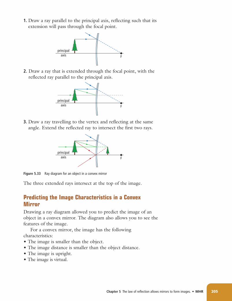
Ray Diagrams for Convex Mirrors Drawing ray diagrams for convex mirrors is very similar to drawing ray diagrams for concave mirrors. By placing the bottom of the object on the principal axis, you know that the bottom of the image will also lie on the principal axis. If you draw three rays from the top of the object, you will be able to predict the image. Remember that all rays will obey the law of reflection. The three rays are the same as the ones you drew in ray diagrams for concave mirrors:
1. Draw a ray parallel to the principal axis, reflecting such that its extension will pass through the focal point.
2. Draw a ray that is extended through the focal point, with the reflected ray parallel to the principal axis.
3. Draw a ray travelling to the vertex and reflecting at the same angle. Extend the reflected ray to intersect the first two rays.
The three extended rays intersect at the top of the image.
Predicting the Image Characteristics in a Convex MirrorDrawing a ray diagram allowed you to predict the image of an object in a convex mirror. The diagram also allows you to see the features of the image.
For a convex mirror, the image has the following characteristics:• The image is smaller than the object.• The image distance is smaller than the object distance.• The image is upright.• The image is virtual.
Using Convex MirrorsConvex mirrors are very useful because they produce an image that is smaller than the object being reflected. Why is this characteristic important? More objects can be seen in a convex mirror than in a plane mirror of the same size. Convex security mirrors make it possible to monitor a large area from a single location. Convex mirrors can also widen the view of traffic that can be seen in rear-view or side-view mirrors in automobiles, large trucks, and school buses (Figure 5.34A). They are often placed at sharp corners in buildings, or even on roads, to allow people to see hazards that would normally be out of view around the corner.
Some streetlights use convex reflector mirrors for a different reason: they reflect light rays away from each other. This casts light out over a large area. A disco ball also makes use of this property (Figure 5.34B).
206 MHR • Unit 2 Optics
Reading Check1. How does the focal point of a convex mirror differ from
that of a concave mirror?2. If the rays of light that reflect from a convex mirror never
meet, how can you use the three rays in a ray diagram to find the image?
3. Do the characteristics of an image in a convex mirror depend on the distance of the object from the mirror? Draw two ray diagrams to illustrate this.
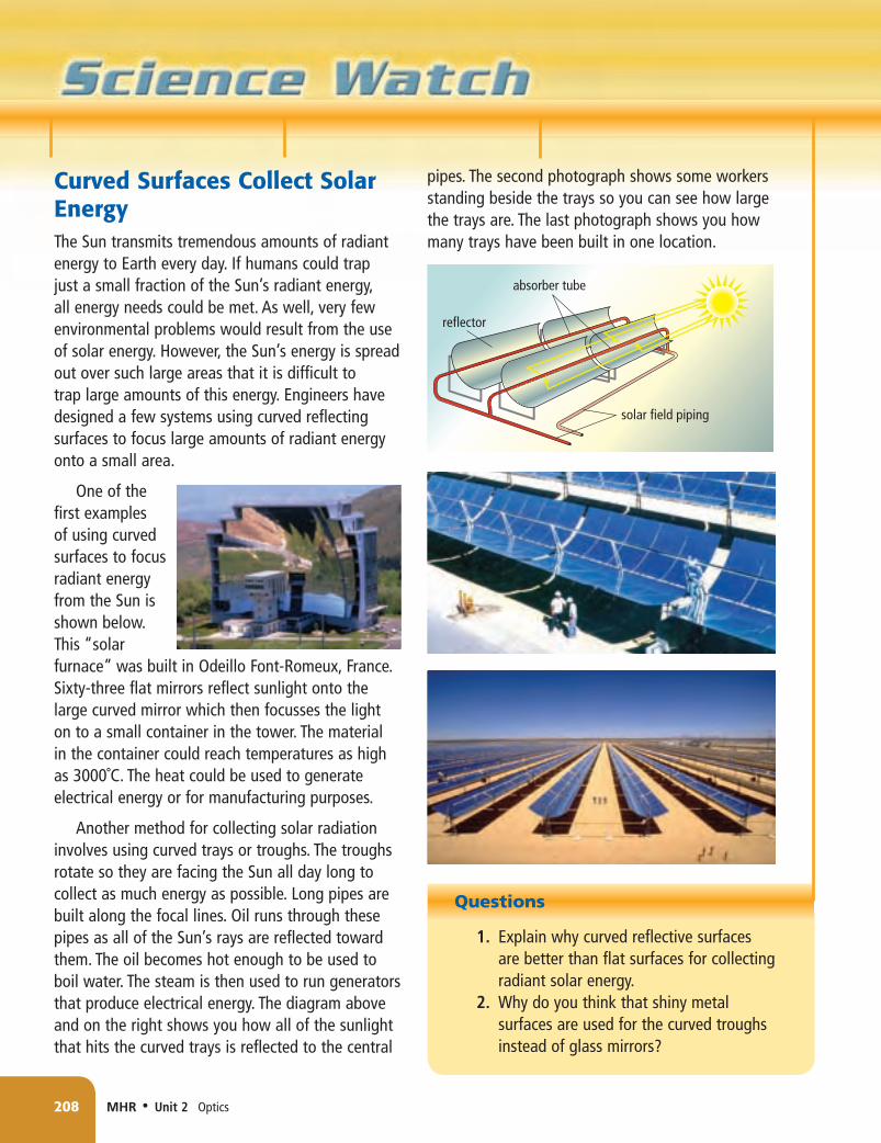
Curved Surfaces Collect Solar Energy TheSuntransmitstremendousamountsofradiantenergytoEartheveryday.IfhumanscouldtrapjustasmallfractionoftheSun’sradiantenergy,allenergyneedscouldbemet.Aswell,veryfewenvironmentalproblemswouldresultfromtheuseofsolarenergy.However,theSun’senergyisspreadoutoversuchlargeareasthatitisdifficulttotraplargeamountsofthisenergy.Engineershavedesignedafewsystemsusingcurvedreflectingsurfacestofocuslargeamountsofradiantenergyontoasmallarea.
Checking Concepts 1. What are the three rays that allow you
to predict an image in a curved mirror? 2. Explain how you would find the focal
point of a concave mirror. 3. Sketch a diagram of a concave mirror
and include the principal axis and the focal point.
4. For both of the situations below, you can use the three-ray technique to determine the image. Will the process you use to draw each of the three rays be exactly the same for (a) and (b)? If not, how will the process differ at each step?
(a)
(b)
5. Name one way in which concave mirrors are commonly used.
6. How does a convex mirror differ from a concave mirror with respect to the appearances of the mirrors?
7. Can a convex mirror form a real image? a virtual image? Use ray diagrams to support your answers.
8. Describe one common use for convex mirrors.
Understanding Key Ideas 9. Would an object placed exactly at the
focal point of a concave mirror produce an image? Use a ray diagram to explain. (Hint: Can you draw the three rays from the top of the object?)
10. Draw two ray diagrams, one for an object in front of a concave mirror and one for a convex mirror. Describe the image characteristics for each drawing.
11. Why is it important to draw a principal axis and place the bottom of the object on the axis when drawing ray diagrams for concave and convex mirrors?
12. Make a sketch that shows how you would find the focal point of a convex mirror.
Prepare Your Own Summary In this chapter, you learned about the law of reflection and about plane, concave, and convex mirrors. You learned how to draw ray diagrams for curved mirrors and to describe the images formed in these mirrors. Create your own summary of the key ideas from this chapter. You may include graphic organizers or illustrations with your notes. Use the following headings to organize your notes. 1. Law of Reflection 2. Specular and Diffuse Reflection 3. Refraction of Light 4. Plane, Concave, and Convex Mirrors 5. Ray Diagrams 6. Uses of Mirrors
Checking Concepts 1. (a) Make a drawing of a flat reflecting
surface with an incident ray, a normal, and a reflected ray.
(b) Use your diagram to explain the law of reflection.
2. Explain the difference between specular reflection and diffuse reflection. Which type of reflection allows you to see an image of yourself in a mirror?
3. Explain how reflected light allows you to read the words on this page.
4. In the diagram above and on the right, a lamp is shining light on a volley ball. Light is reflected off all parts of the ball. Two rays that reflect from one point on the ball are shown hitting a plane mirror and reflecting from it. Sketch a similar diagram and use it to show how you would find the image of the same point on the volley ball.
5. Examine the sketch you made for question 4. Is the image real or virtual? Explain.
6. Copy the following drawings in your notebook.
(a) Complete ray diagrams for both drawings.
(b) Use your ray diagrams to show and explain how a concave mirror can form upright images and inverted images.
(c) For each image, state whether it is real or virtual.
7. Why are concave mirrors often used for makeup mirrors or shaving mirrors?
8. How does the image in a shaving mirror change as you move the mirror from arm's length in toward your face?
9. Copy the diagram below into your notebook. Place an object on the principal axis in a location that will form an image that is real, inverted, and smaller than the object. Complete the ray diagram to demonstrate that the image is real, inverted, and smaller than the object. (You might have to try more than once.)
10. Explain how you would make a convex mirror from a piece of a shiny sphere.
11. (a) Draw a horizontal line and a convex mirror passing through the centre of the horizontal line.
(b) Label the horizontal line “principal axis.”
(c) Label the vertical line “convex mirror.”
(d) Place an object on the left side of the convex mirror.
(e) Mark the focal point on the principal axis in the correct position for a convex mirror.
(f) Complete the ray diagram. (g) State whether the image is real or
virtual, upright or inverted, and whether it is larger or smaller than the object.
Understanding Key Ideas 12. Explain how the law of reflection can
account for both specular reflection and diffuse reflection.
13. Explain how you can use a screen to determine whether an image is real or virtual.
14. How does placing the bottom of an object on the principal axis make it easier to locate an image in a ray diagram?
15. Why is the flashlight bulb placed at the focal point of the curved reflector in a flashlight?


![Anisotropic Diffusion of Surfaces and Functions on Surfaces · Zhao et al. [2001, 2000]). In these methods, surfaces are formulated as isosurfaces (level surfaces) of 3D functions,](https://static.documents.pub/doc/80x56/604a4b1cd8577906ef6a6ad5/anisotropic-diffusion-of-surfaces-and-functions-on-surfaces-zhao-et-al-2001-2000.jpg)


