Barudan Technical Sewing Head Maintenance Manual 8/1/97 YS-E & A Sewing Head B 2-1 TOOLS NEEDED 3 mm Allen Wrench Needle Screwdriver Flathead Screwdriver Offset Screwdriver Flashlight New Needle Cleaning Brush NEEDLE DEPTH ADJUSTMENT PURPOSE: The needle must rise 2-3 mm from bottom dead center thus forming a loop behind the needle. As the hook point passes behind the needle it captures the formed loop. If the Needle Bar is too high or too low the sewing quality is effected. The needle can not capture the loop therefore a stitch will not be formed or not form properly. CAUSES: < Red caps worn or broken. < Broken needle. < “Slam” into hoop. < Changed needle brand. SYMPTOMS: < Skip Stitches < Looping < Fraying < Breaking Thread < Breaking Needles PROCEDURE: 1. Power down Embroidery Machine 2. Disengage Needle Bar Driver. 3. Pull thread Keep Lever forward to disengage Thread Apron Clamps. See Figure 1 .
Transcript
Barudan Technical Sewing Head Maintenance Manual8/1/97
YS-E & A Sewing Head B2-1
TOOLS NEEDED3 mm Allen WrenchNeedle Screwdriver
Flathead ScrewdriverOffset Screwdriver
FlashlightNew Needle
Cleaning Brush
NEEDLE DEPTH ADJUSTMENT
PURPOSE:The needle must rise 2-3 mm from bottom dead center thus forming a loop behind the needle. Asthe hook point passes behind the needle it captures the formed loop. If the Needle Bar is too highor too low the sewing quality is effected. The needle can not capture the loop therefore a stitch willnot be formed or not form properly.
CAUSES:< Red caps worn or broken.< Broken needle.< “Slam” into hoop.< Changed needle brand.
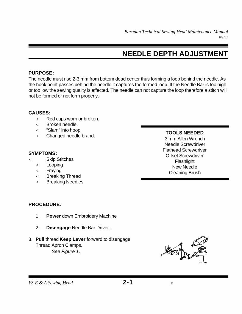
3. Pull thread Keep Lever forward to disengageThread Apron Clamps.
See Figure 1.
Barudan Technical Sewing Head Maintenance Manual8/1/97
YS-E & A Sewing Head b2-2
Figure 2
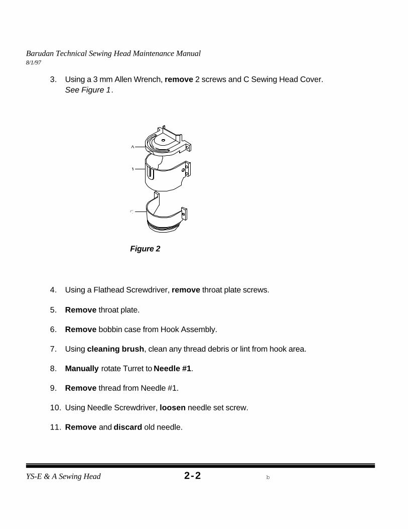
3. Using a 3 mm Allen Wrench, remove 2 screws and C Sewing Head Cover. See Figure 1.
4. Using a Flathead Screwdriver, remove throat plate screws.
5. Remove throat plate.
6. Remove bobbin case from Hook Assembly.
7. Using cleaning brush, clean any thread debris or lint from hook area.
8. Manually rotate Turret to Needle #1.
9. Remove thread from Needle #1.
10. Using Needle Screwdriver, loosen needle set screw.
11. Remove and discard old needle.
Barudan Technical Sewing Head Maintenance Manual8/1/97
YS-E & A Sewing Head B2-3
Figure 2
Figure 3
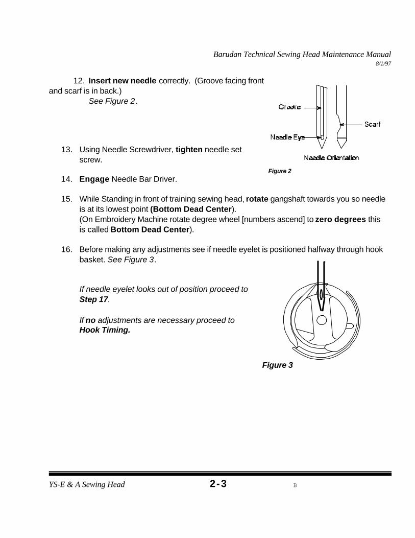
12. Insert new needle correctly. (Groove facing frontand scarf is in back.)
See Figure 2.
13. Using Needle Screwdriver, tighten needle setscrew.
14. Engage Needle Bar Driver.
15. While Standing in front of training sewing head, rotate gangshaft towards you so needleis at its lowest point (Bottom Dead Center). (On Embroidery Machine rotate degree wheel [numbers ascend] to zero degrees thisis called Bottom Dead Center).
16. Before making any adjustments see if needle eyelet is positioned halfway through hookbasket. See Figure 3.
If needle eyelet looks out of position proceed to Step 17.
If no adjustments are necessary proceed toHook Timing.
Barudan Technical Sewing Head Maintenance Manual8/1/97
YS-E & A Sewing Head b2-4
Figure 4
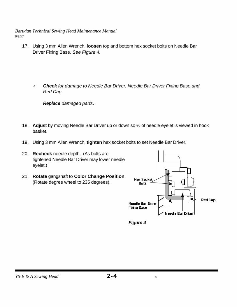
17. Using 3 mm Allen Wrench, loosen top and bottom hex socket bolts on Needle BarDriver Fixing Base. See Figure 4.
< Check for damage to Needle Bar Driver, Needle Bar Driver Fixing Base andRed Cap.
Replace damaged parts.
18. Adjust by moving Needle Bar Driver up or down so ½ of needle eyelet is viewed in hookbasket.
19. Using 3 mm Allen Wrench, tighten hex socket bolts to set Needle Bar Driver.
20. Recheck needle depth. (As bolts aretightened Needle Bar Driver may lower needleeyelet.)
21. Rotate gangshaft to Color Change Position.
(Rotate degree wheel to 235 degrees).
Barudan Technical Sewing Head Maintenance Manual8/1/97
YS-E & A Sewing Head B2-5
Note: If symptoms are still occurring proceed to Hook Timing.
22. Reinstall throat plate.
23. Using Flathead Screwdriver, tighten throat plate screws.
24. Reinstall bobbin case.
25. Using 3 mm Allen Wrench, replace Sewing Head Cover.
26. Using enclosed disk, sew the “HOX” test to check for proper adjustment.
Barudan Technical Sewing Head Maintenance Manual8/1/97
Hook timing is probably the most misunderstood aspect of embroidery machine mechanics. Ithas nothing to do with the type of fabric, tension or synchronization of the heads on a multi-headmachine.
PURPOSE:Hook timing is the proper position of the Hook Assembly in relation to the needle in order to forma stitch. The hook is directly attached to the drive shaft, eliminating the need to routinely re-timeit.
CAUSES:< Something gets caught in Hook Assembly.< Size of needle has drastically changed.< A build-up of thread behind hook pushes hook out of
line.
SYMPTOMS:< Machine fails to form or complete a stitch. < Excessive Needle Breaks.< Thread Frays< “Birdnesting”
PROCEDURE:Needle depth must be checked before timing the hook.
A. PREPARATION
1. Power down Embroidery Machine.
2. Disengage Needle Bar Driver.
3. Using a Flathead Screwdriver, remove throat plate screws.
4. Remove throat plate.
5. Remove bobbin case from Hook Assembly.
Barudan Technical Sewing Head Maintenance Manual8/1/97
YS-E & A Sewing Head b2-7
Figure 1
6. Using cleaning brush, clean any thread debris or lint from hook area.
7. Rotate gangshaft until Take-up Levers are in up position. (On Embroidery Machinerotate degree wheel [numbers ascend] to 235 degrees).
8. With finger, check entire Hook Assembly for burrs or nicks.
If burrs or nicks are present on Hook Assembly continue to Section B.
If Hook Assembly is not damaged continue to Section C.
B. HOOK ASSEMBLY REPLACEMENT
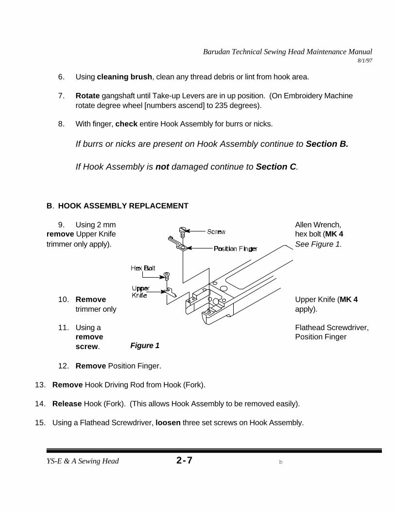
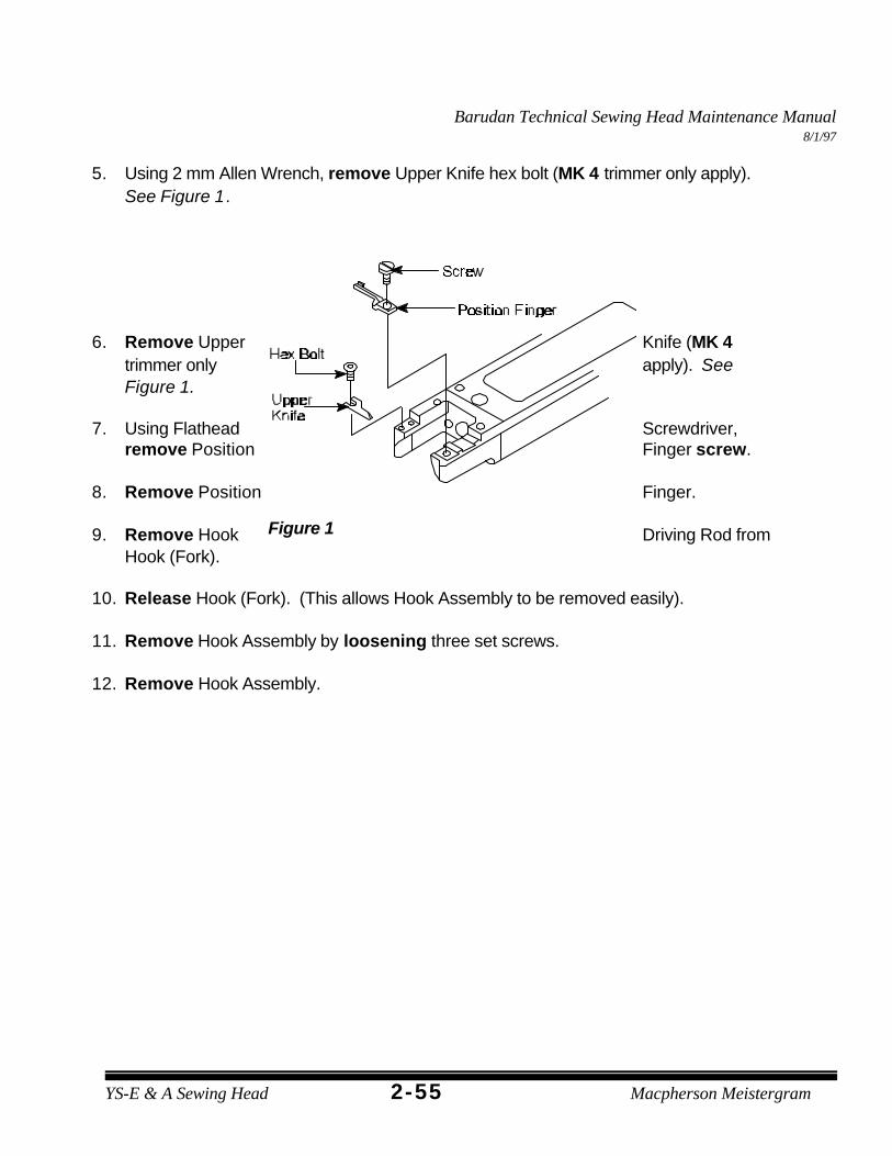
9. Using 2 mm Allen Wrench,remove Upper Knife hex bolt (MK 4trimmer only apply). See Figure 1.
10. Remove Upper Knife (MK 4trimmer only apply).
11. Using a Flathead Screwdriver,remove Position Fingerscrew.
12. Remove Position Finger.
13. Remove Hook Driving Rod from Hook (Fork).
14. Release Hook (Fork). (This allows Hook Assembly to be removed easily).
15. Using a Flathead Screwdriver, loosen three set screws on Hook Assembly.
Barudan Technical Sewing Head Maintenance Manual8/1/97
YS-E & A Sewing Head b2-8
Note: If burrs or nicks can not be smoothed, replace with new HookAssembly.
Figure 2
16. Remove Hook Assembly.
17. Gently rub burred or nicked area of Hook Assembly with emery or crocus cloth untilsmooth.
18. Rotate gangshaft to Color Change Position. (Rotate degree wheel to 235 degrees).
19. Insert repaired or new Hook Assembly on bottom shaft.
20. Replace Position Finger.
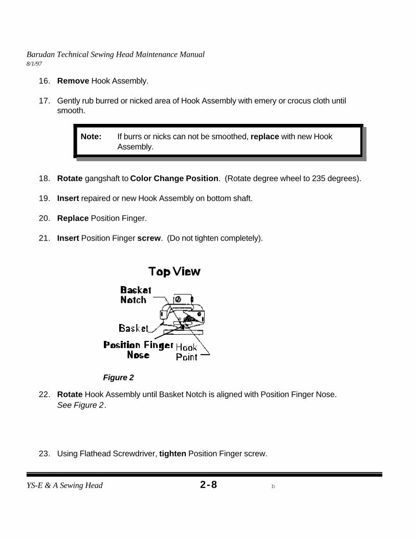
21. Insert Position Finger screw. (Do not tighten completely).
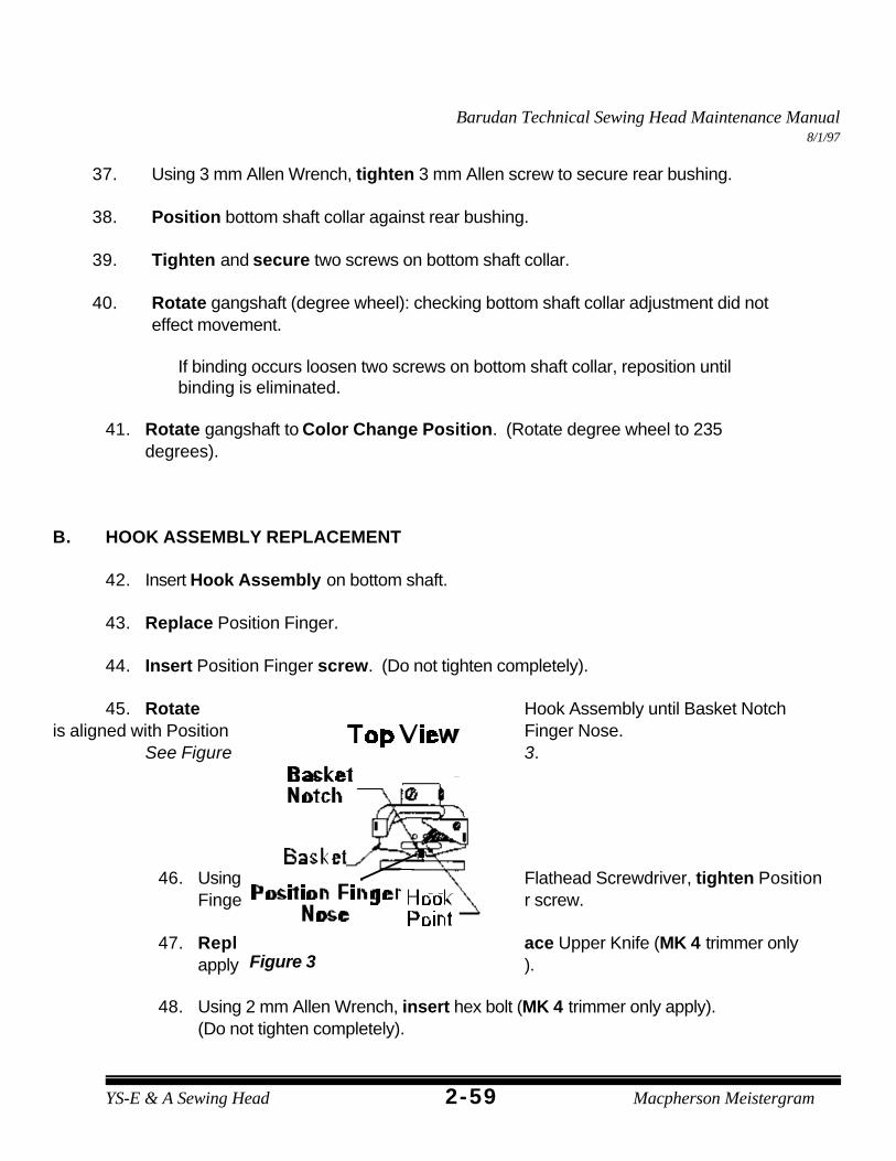
22. Rotate Hook Assembly until Basket Notch is aligned with Position Finger Nose. See Figure 2.
23. Using Flathead Screwdriver, tighten Position Finger screw.
Barudan Technical Sewing Head Maintenance Manual8/1/97
YS-E & A Sewing Head b2-9
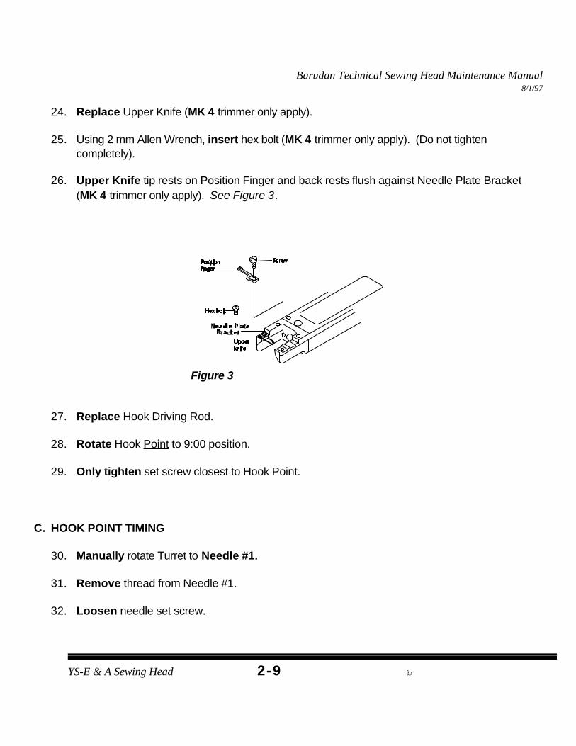
24. Replace Upper Knife (MK 4 trimmer only apply).
25. Using 2 mm Allen Wrench, insert hex bolt (MK 4 trimmer only apply). (Do not tightencompletely).
26. Upper Knife tip rests on Position Finger and back rests flush against Needle Plate Bracket(MK 4 trimmer only apply). See Figure 3.
Figure 3
27. Replace Hook Driving Rod.
28. Rotate Hook Point to 9:00 position.
29. Only tighten set screw closest to Hook Point.
C. HOOK POINT TIMING
30. Manually rotate Turret to Needle #1.
31. Remove thread from Needle #1.
32. Loosen needle set screw.
Barudan Technical Sewing Head Maintenance Manual8/1/97
YS-E & A Sewing Head b2-10
Figure 4
Figure 5
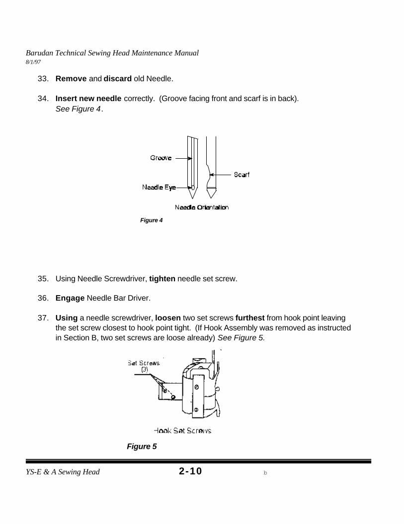
33. Remove and discard old Needle.
34. Insert new needle correctly. (Groove facing front and scarf is in back). See Figure 4.
35. Using Needle Screwdriver, tighten needle set screw.
36. Engage Needle Bar Driver.
37. Using a needle screwdriver, loosen two set screws furthest from hook point leavingthe set screw closest to hook point tight. (If Hook Assembly was removed as instructedin Section B, two set screws are loose already) See Figure 5.
Barudan Technical Sewing Head Maintenance Manual8/1/97
YS-E & A Sewing Head b2-11
Figure 6
(Degree Wheel: First screw=115 degrees; Second screw=175 degrees)
38. While Standing in front of training sewing head, rotate gangshaft towards you so needleis at its lowest point (Bottom Dead Center). (Rotate degree wheel to zero degrees this is called Bottom Dead Center).
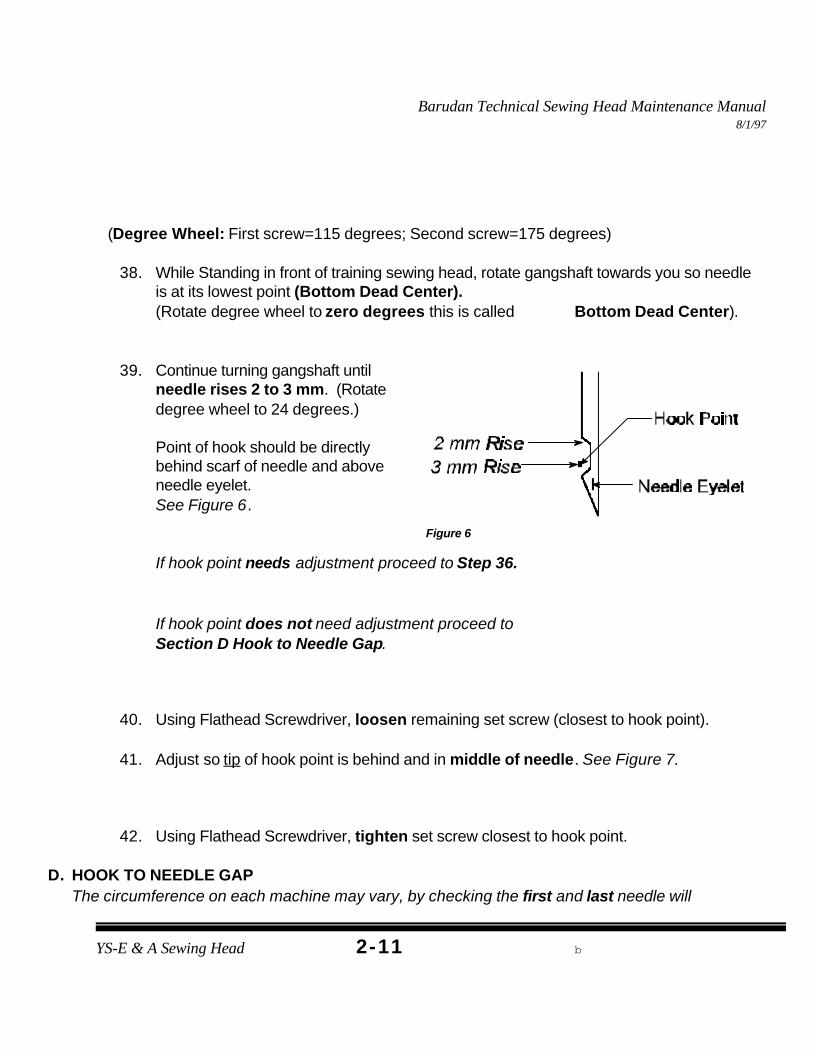
39. Continue turning gangshaft untilneedle rises 2 to 3 mm. (Rotatedegree wheel to 24 degrees.)
Point of hook should be directlybehind scarf of needle and aboveneedle eyelet. See Figure 6.
If hook point needs adjustment proceed to Step 36.
If hook point does not need adjustment proceed to Section D Hook to Needle Gap.
40. Using Flathead Screwdriver, loosen remaining set screw (closest to hook point).
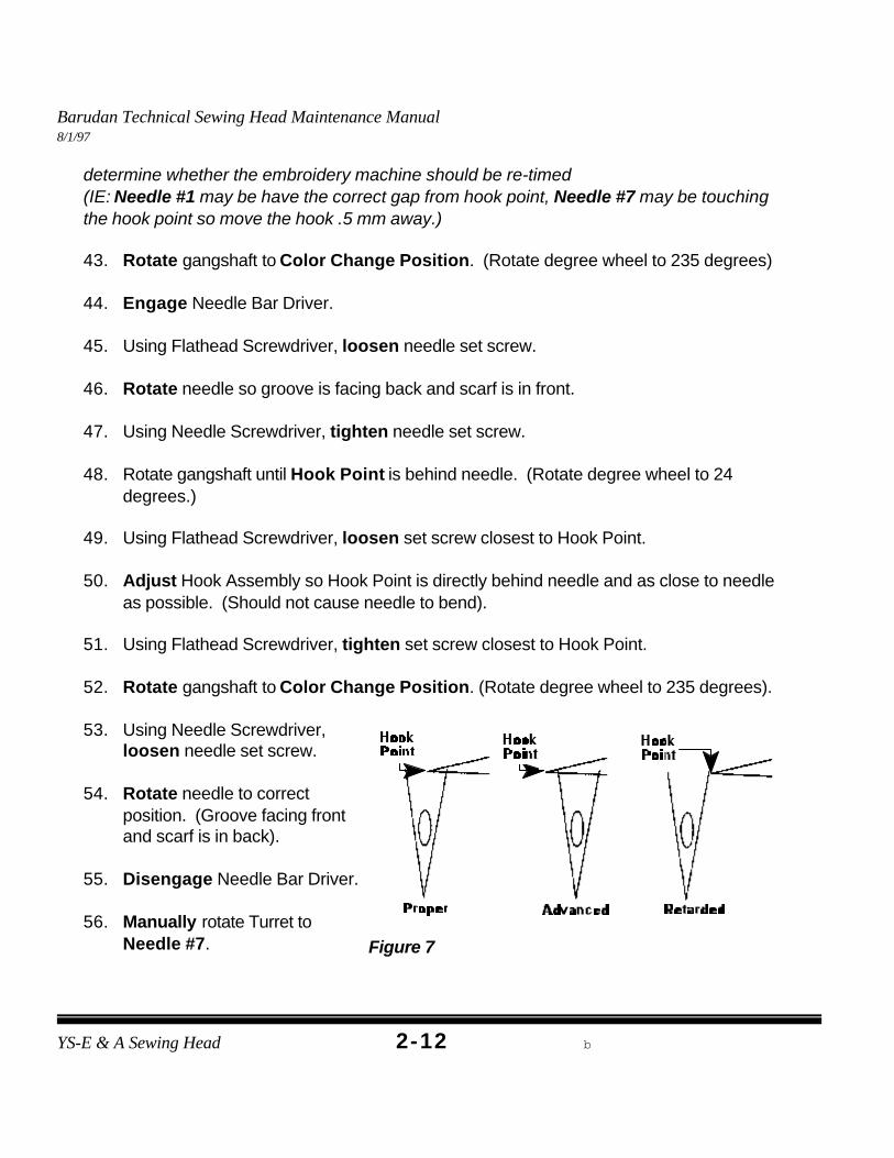
41. Adjust so tip of hook point is behind and in middle of needle. See Figure 7.
42. Using Flathead Screwdriver, tighten set screw closest to hook point.
D. HOOK TO NEEDLE GAPThe circumference on each machine may vary, by checking the first and last needle will
Barudan Technical Sewing Head Maintenance Manual8/1/97
YS-E & A Sewing Head b2-12
Figure 7
determine whether the embroidery machine should be re-timed (IE: Needle #1 may be have the correct gap from hook point, Needle #7 may be touchingthe hook point so move the hook .5 mm away.)
43. Rotate gangshaft to Color Change Position. (Rotate degree wheel to 235 degrees)
44. Engage Needle Bar Driver.
45. Using Flathead Screwdriver, loosen needle set screw.
46. Rotate needle so groove is facing back and scarf is in front.
47. Using Needle Screwdriver, tighten needle set screw.
48. Rotate gangshaft until Hook Point is behind needle. (Rotate degree wheel to 24degrees.)
49. Using Flathead Screwdriver, loosen set screw closest to Hook Point.
50. Adjust Hook Assembly so Hook Point is directly behind needle and as close to needleas possible. (Should not cause needle to bend).
51. Using Flathead Screwdriver, tighten set screw closest to Hook Point.
52. Rotate gangshaft to Color Change Position. (Rotate degree wheel to 235 degrees).
53. Using Needle Screwdriver,loosen needle set screw.
54. Rotate needle to correctposition. (Groove facing frontand scarf is in back).
55. Disengage Needle Bar Driver.
56. Manually rotate Turret toNeedle #7.
Barudan Technical Sewing Head Maintenance Manual8/1/97
YS-E & A Sewing Head b2-13
57. Remove thread from Needle #7.
58. Using Needle Screwdriver, loosen needle set screw.
59. Insert new needle, groove is facing back and scarf is in front.
60. Using Needle Screwdriver, tighten needle set screw.
61. Engage Needle Bar Driver.
62. Rotate gangshaft until Hook Point is behind needle. (Rotate degree wheel to 24degrees).
63. Hook Point should be directly behind needle and as close to needle as possible. (Should not cause needle to bend).
If Hook Point causes needle to bend on Needle #7 then adjust Hook Point 0.5 mm away from needle.
64. Using Flathead Screwdriver, tighten two remaining set screws (furthest from hookpoint).
65. Rotate gangshaft to Color Change Position. (Rotate degree wheel to 235 degrees).
66. Using Needle Screwdriver, loosen needle set screw.
67. Rotate needle to correct position. (Groove facing front and scarf is in back).
68. Using Needle Screwdriver, tighten needle set screw.
69. Proceed to Position Finger Adjustment.
Barudan Technical Sewing Head Maintenance Manual8/1/97
YS-E & A Sewing Head b2-14
TOOLS NEEDEDSmall Flathead Screwdriver
Figure 1
NOTE: Bobbin thread may not be centered if adjustment is incorrect.
POSITION FINGER ADJUSTMENT
DEFINITION:The Position Finger secures the hook basket in place and guides the bobbin thread to fabric.
CAUSES:< Replaced Hook Assembly.< Position Finger set screw not secure.
SYMPTOMS:< Bobbin thread underside of garment not
centered.< No bobbin thread-”looping”.
PROCEDURE:
1. Engage Needle Bar Driver.
2. Rotate gangshaft until needle reaches it’s lowest point, Bottom Dead center. (OnEmbroidery Machine rotate degree wheel [numbers ascend] to zero degrees this iscalled Bottom Dead Center.
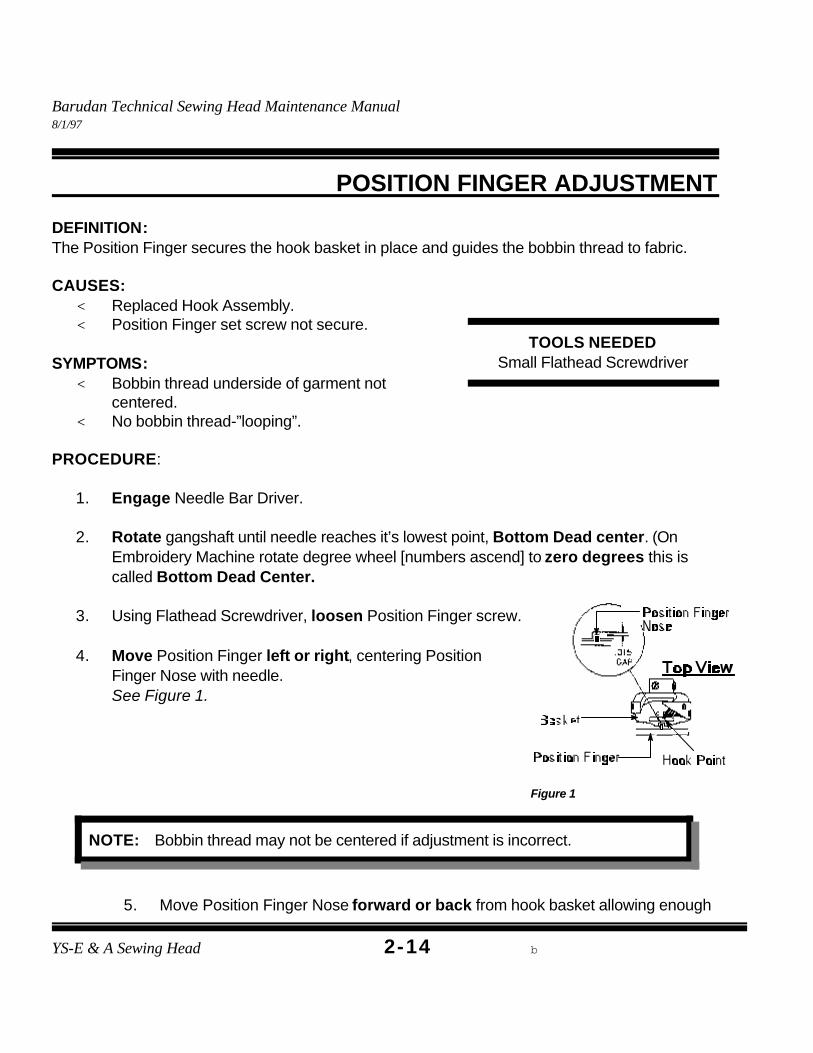
3. Using Flathead Screwdriver, loosen Position Finger screw.
4. Move Position Finger left or right, centering PositionFinger Nose with needle. See Figure 1.
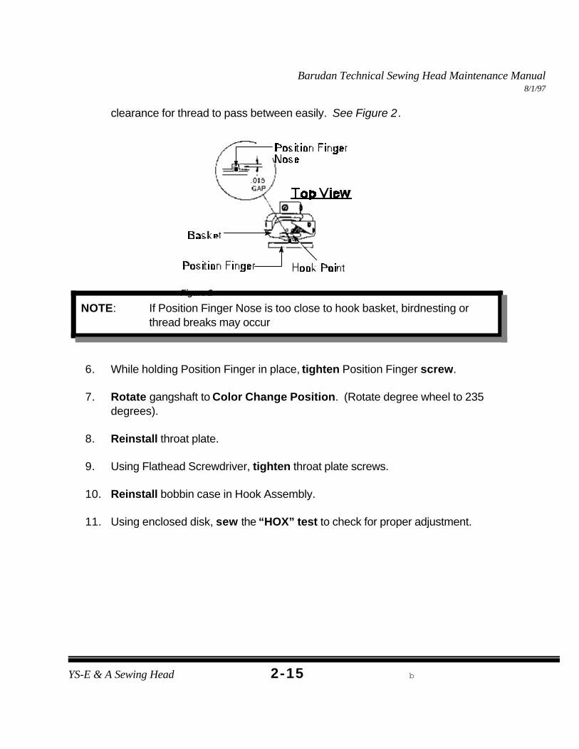
5. Move Position Finger Nose forward or back from hook basket allowing enough
Barudan Technical Sewing Head Maintenance Manual8/1/97
YS-E & A Sewing Head b2-15
Figure 2
NOTE: If Position Finger Nose is too close to hook basket, birdnesting orthread breaks may occur
clearance for thread to pass between easily. See Figure 2.
6. While holding Position Finger in place, tighten Position Finger screw.
7. Rotate gangshaft to Color Change Position. (Rotate degree wheel to 235degrees).
8. Reinstall throat plate.
9. Using Flathead Screwdriver, tighten throat plate screws.
10. Reinstall bobbin case in Hook Assembly.
11. Using enclosed disk, sew the “HOX” test to check for proper adjustment.
Barudan Technical Sewing Head Maintenance Manual8/1/97
YS-E & A Sewing Head b2-16
TOOLS NEEDED3 mm Allen Wrench
2.5 mm Allen Wrench2 mm Allen Wrench
Small Flathead ScrewdriverNeedle ScrewdriverOffset Screwdriver
New NeedlesNew Needle Bar
New Small SpringFlashlight
Figure 1
NEEDLE BAR REPLACEMENT
DEFINITION:The Needle Bar holds the needle and moves up and down.
CAUSES:< Bent < Burrs< Lack of Lubrication
SYMPTOMS:< Little or no movement up or down.< Skip Stitches.< Breaking needles
PROCEDURE:
A. NEEDLE BAR REPLACEMENT
1. Power down Embroidery Machine.
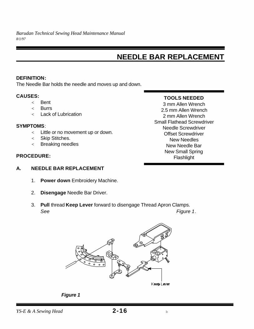
2. Disengage Needle Bar Driver.
3. Pull thread Keep Lever forward to disengage Thread Apron Clamps. See Figure 1.
Barudan Technical Sewing Head Maintenance Manual8/1/97
2-17
Figure 2
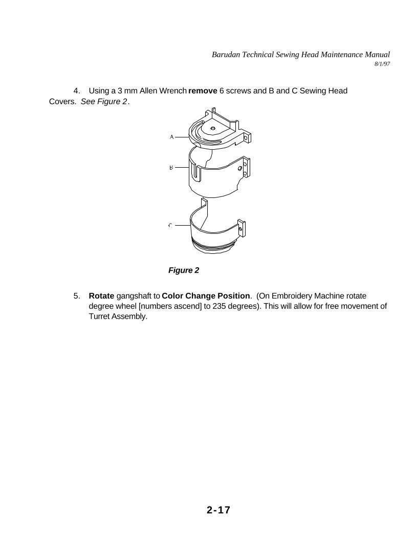
4. Using a 3 mm Allen Wrench remove 6 screws and B and C Sewing HeadCovers. See Figure 2.
5. Rotate gangshaft to Color Change Position. (On Embroidery Machine rotatedegree wheel [numbers ascend] to 235 degrees). This will allow for free movement ofTurret Assembly.
Barudan Technical Sewing Head Maintenance Manual8/1/97
YS-E & A Sewing Head b2-18
Figure 3
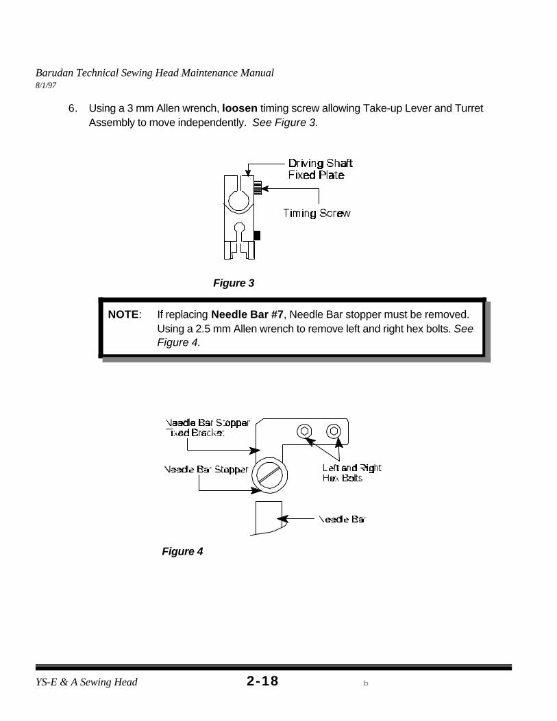
NOTE: If replacing Needle Bar #7, Needle Bar stopper must be removed. Using a 2.5 mm Allen wrench to remove left and right hex bolts. SeeFigure 4.
Figure 4
6. Using a 3 mm Allen wrench, loosen timing screw allowing Take-up Lever and TurretAssembly to move independently. See Figure 3.
Barudan Technical Sewing Head Maintenance Manual8/1/97
YS-E & A Sewing Head B2-19
NOTE: If removing Needle Bar #7 rotate Turret to Needle #6 andmanually rotate Turret Assembly to far left.
Figure 5
7. Move Take-Up Assembly opposite of Turret Assembly. (Allowing needle to beremoved easily).
8. Using a Needle Screwdriver, loosen needle set screw and remove needle.
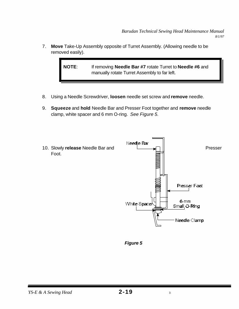
9. Squeeze and hold Needle Bar and Presser Foot together and remove needleclamp, white spacer and 6 mm O-ring. See Figure 5.
10. Slowly release Needle Bar and PresserFoot.
Barudan Technical Sewing Head Maintenance Manual8/1/97
YS-E & A Sewing Head b2-20
Figure 6
NOTE: If removing Needle Bar #7, rotate Needle Bar counterclockwise90 degrees, this enables Needle Bar to pass stopper bracket.
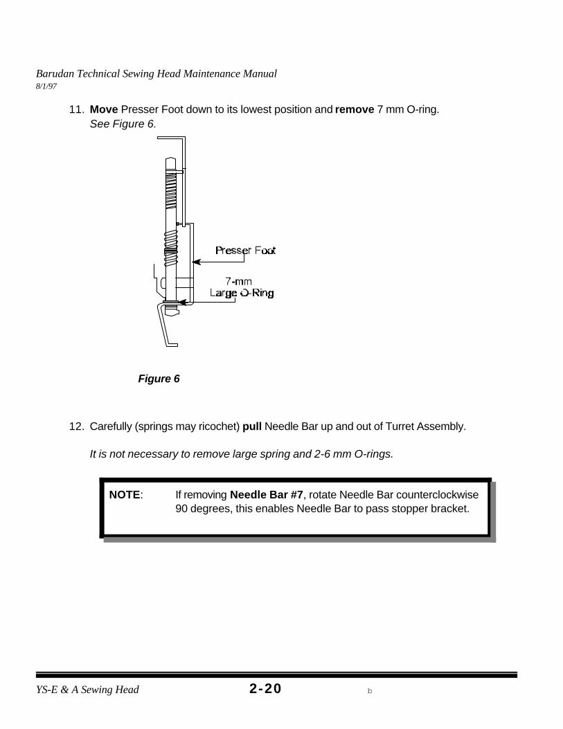
11. Move Presser Foot down to its lowest position and remove 7 mm O-ring. See Figure 6.
12. Carefully (springs may ricochet) pull Needle Bar up and out of Turret Assembly.
It is not necessary to remove large spring and 2-6 mm O-rings.
Barudan Technical Sewing Head Maintenance Manual8/1/97
YS-E & A Sewing Head B2-21
Figure 7
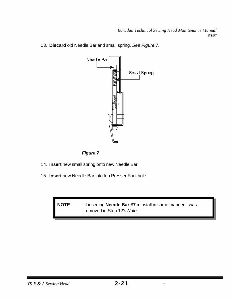
NOTE: If inserting Needle Bar #7 reinstall in same manner it wasremoved in Step 12's Note.
13. Discard old Needle Bar and small spring. See Figure 7.
14. Insert new small spring onto new Needle Bar.
15. Insert new Needle Bar into top Presser Foot hole.
Barudan Technical Sewing Head Maintenance Manual8/1/97
YS-E & A Sewing Head b2-22
Figure 8
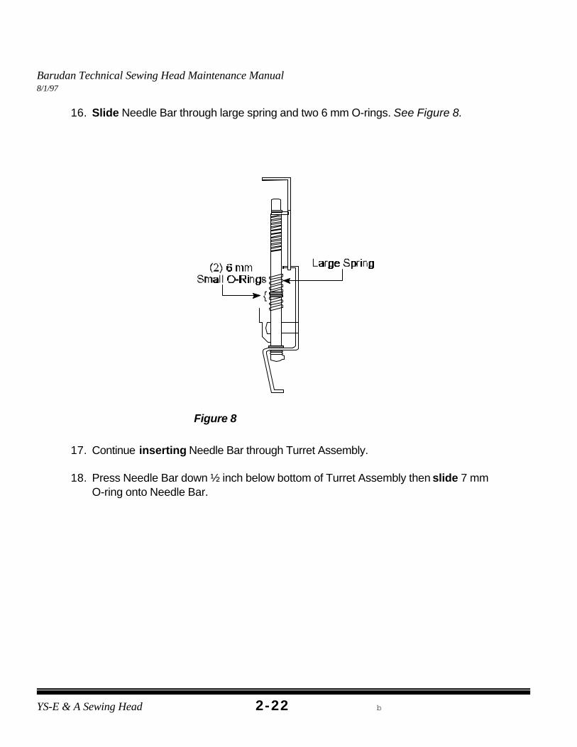
16. Slide Needle Bar through large spring and two 6 mm O-rings. See Figure 8.
17. Continue inserting Needle Bar through Turret Assembly.
18. Press Needle Bar down ½ inch below bottom of Turret Assembly then slide 7 mm O-ring onto Needle Bar.
Barudan Technical Sewing Head Maintenance Manual8/1/97
YS-E & A Sewing Head B2-23
Figure 9
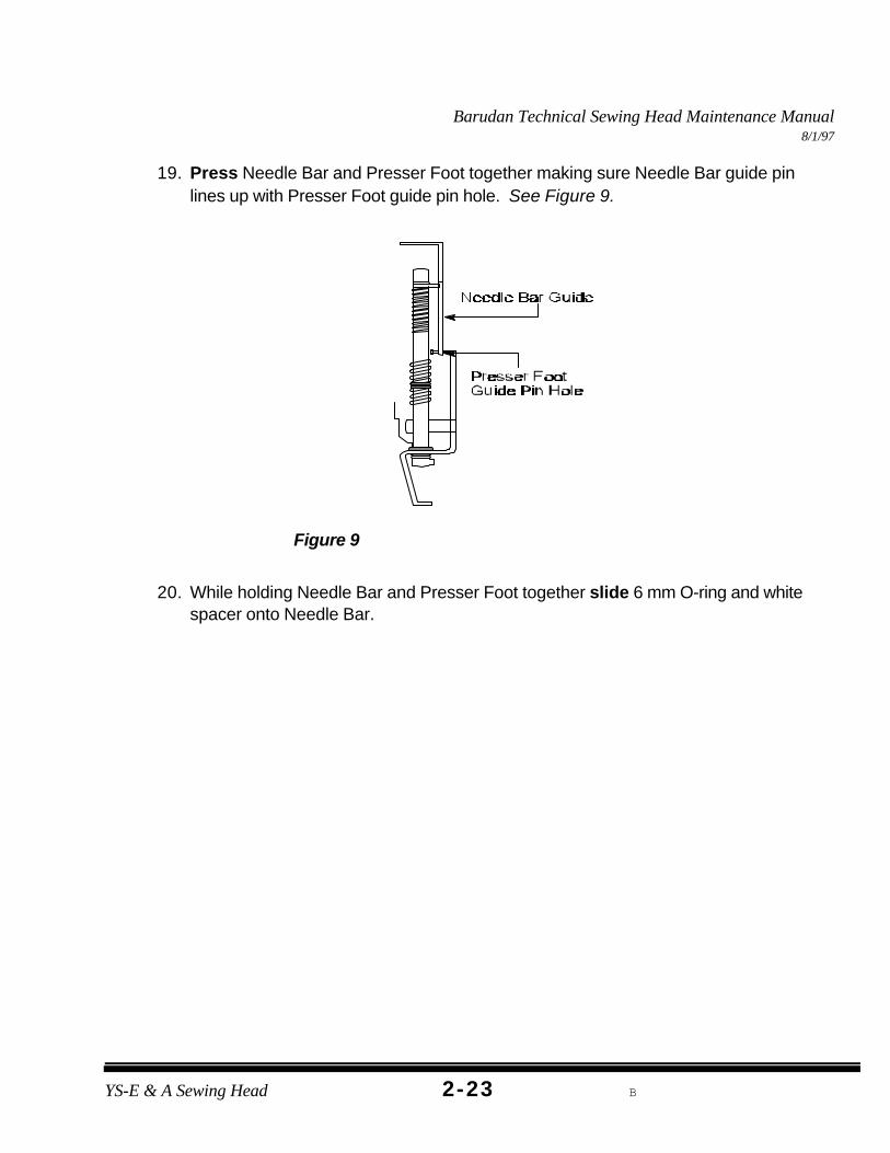
19. Press Needle Bar and Presser Foot together making sure Needle Bar guide pinlines up with Presser Foot guide pin hole. See Figure 9.
20. While holding Needle Bar and Presser Foot together slide 6 mm O-ring and whitespacer onto Needle Bar.
Barudan Technical Sewing Head Maintenance Manual8/1/97
YS-E & A Sewing Head b2-24
Figure 10
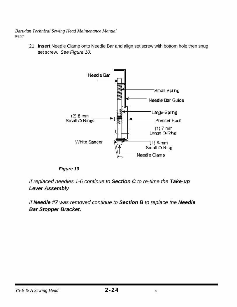
21. Insert Needle Clamp onto Needle Bar and align set screw with bottom hole then snugset screw. See Figure 10.
If replaced needles 1-6 continue to Section C to re-time the Take-upLever Assembly
If Needle #7 was removed continue to Section B to replace the NeedleBar Stopper Bracket.
Barudan Technical Sewing Head Maintenance Manual8/1/97
YS-E & A Sewing Head B2-25
Figure 11
Figure 12
B. NEEDLE BAR STOPPER BRACKET REPLACEMENT
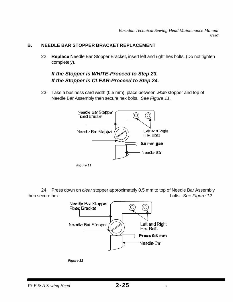
22. Replace Needle Bar Stopper Bracket, insert left and right hex bolts. (Do not tightencompletely).
If the Stopper is WHITE-Proceed to Step 23.If the Stopper is CLEAR-Proceed to Step 24.
23. Take a business card width (0.5 mm), place between white stopper and top ofNeedle Bar Assembly then secure hex bolts. See Figure 11.
24. Press down on clear stopper approximately 0.5 mm to top of Needle Bar Assemblythen secure hex bolts. See Figure 12.
Barudan Technical Sewing Head Maintenance Manual8/1/97
YS-E & A Sewing Head b2-26
Figure 13
NOTE: The Take-up Lever may be centered with Take-up Driving Roller onNeedle #7 but to check for accurate alignment you must alsocheck Needle #1.
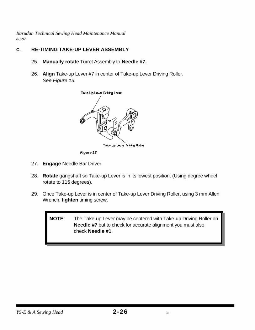
C. RE-TIMING TAKE-UP LEVER ASSEMBLY
25. Manually rotate Turret Assembly to Needle #7.
26. Align Take-up Lever #7 in center of Take-up Lever Driving Roller. See Figure 13.
27. Engage Needle Bar Driver.
28. Rotate gangshaft so Take-up Lever is in its lowest position. (Using degree wheelrotate to 115 degrees).
29. Once Take-up Lever is in center of Take-up Lever Driving Roller, using 3 mm AllenWrench, tighten timing screw.
Barudan Technical Sewing Head Maintenance Manual8/1/97
YS-E & A Sewing Head B2-27
NOTE: If gangshaft does not rotate freely there may not be enoughclearance between Take-up Lever and Take-up Driving Roller Arm.Take-up Lever #7 may have to be adjusted slightly right of center toallow clearance for Take-up Lever #1.
30. Rotate gangshaft to Color Change Position. (Rotate degree wheel to 235degrees).
31. Disengage Needle Bar Driver.
32. Manually Rotate Turret Assembly to Needle #1.
33. Engage Needle Bar Driver.
34. While slowly rotating gangshaft (do not force), check to insure proper clearancebetween Take-up Lever and Take-up Driving Roller Arm until Take-up Lever is in itslowest position. (Using the degree wheel rotate to 115 degrees).
35. Using 3 mm Allen Wrench, replace Sewing Head Covers.
36. Using enclosed disk, sew the “HOX” test to check for proper adjustment.
Barudan Technical Sewing Head Maintenance Manual8/1/97
YS-E & A Sewing Head b2-28
TOOLS NEEDED3 mm Allen Wrench
2.5 mm Allen Wrench2 mm Allen WrenchNeedle ScrewdriverOffset Screwdriver
Small Flathead ScrewdriverNeedle Nose PliersNew Presser Foot
FlashlightMOST PRESSER FEET CAN BE BENT BACK
INTO SHAPE.
PRESSER FOOT REPLACEMENT
DEFINITION:Presses down on material to prevent flagging.
Barudan Technical Sewing Head Maintenance Manual8/1/97
2-29YS-E & A Sewing Head Macpherson Meistergram
Figure 1
Figure 2
Figure 3
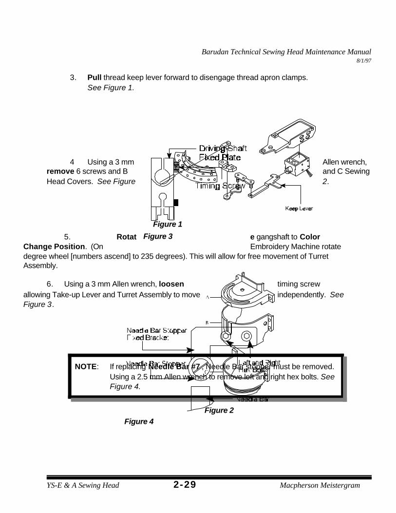
NOTE: If replacing Needle Bar #7 , Needle Bar stopper must be removed.Using a 2.5 mm Allen wrench to remove left and right hex bolts. SeeFigure 4.
Figure 4
3. Pull thread keep lever forward to disengage thread apron clamps. See Figure 1.
4 Using a 3 mm Allen wrench,remove 6 screws and B and C SewingHead Covers. See Figure 2.
5. Rotat e gangshaft to ColorChange Position. (On Embroidery Machine rotatedegree wheel [numbers ascend] to 235 degrees). This will allow for free movement of TurretAssembly.
6. Using a 3 mm Allen wrench, loosen timing screwallowing Take-up Lever and Turret Assembly to move independently. SeeFigure 3.
Barudan Technical Sewing Head Maintenance Manual8/1/97
YS-E & A Sewing Head b2-30
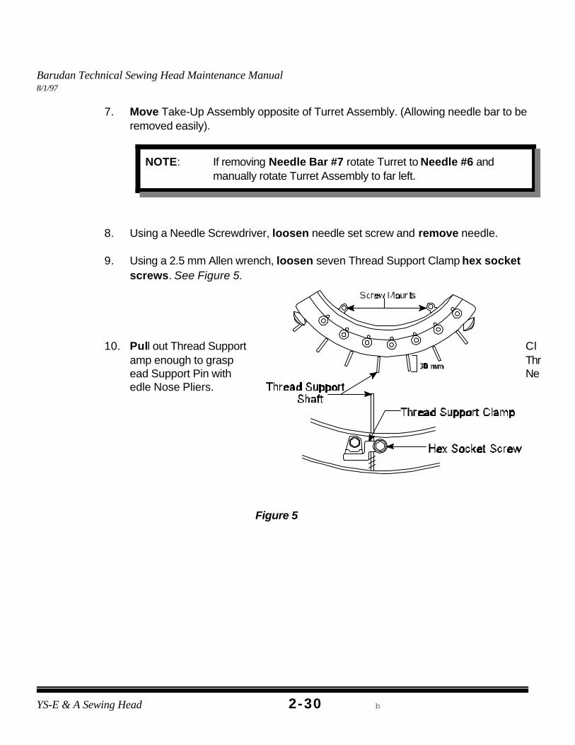
NOTE: If removing Needle Bar #7 rotate Turret to Needle #6 andmanually rotate Turret Assembly to far left.
Figure 5
7. Move Take-Up Assembly opposite of Turret Assembly. (Allowing needle bar to beremoved easily).
8. Using a Needle Screwdriver, loosen needle set screw and remove needle.
9. Using a 2.5 mm Allen wrench, loosen seven Thread Support Clamp hex socketscrews. See Figure 5.
10. Pull out Thread Support Clamp enough to grasp Thread Support Pin with Needle Nose Pliers.
Barudan Technical Sewing Head Maintenance Manual8/1/97
2-31YS-E & A Sewing Head Macpherson Meistergram
Figure 6
Figure 7
Figure 8
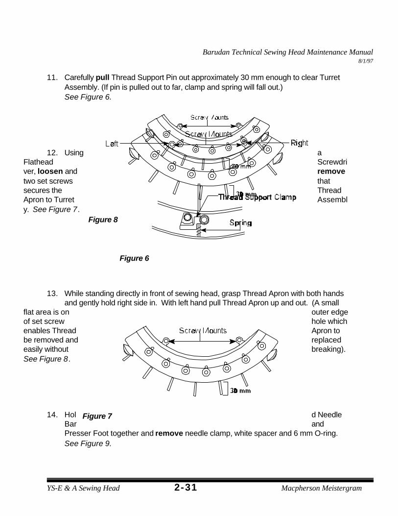
11. Carefully pull Thread Support Pin out approximately 30 mm enough to clear TurretAssembly. (If pin is pulled out to far, clamp and spring will fall out.) See Figure 6.
12. Using aFlathead Screwdriver, loosen and removetwo set screws thatsecures the ThreadApron to Turret Assembly. See Figure 7.
13. While standing directly in front of sewing head, grasp Thread Apron with both handsand gently hold right side in. With left hand pull Thread Apron up and out. (A small
flat area is on outer edgeof set screw hole whichenables Thread Apron tobe removed and replacedeasily without breaking). See Figure 8.
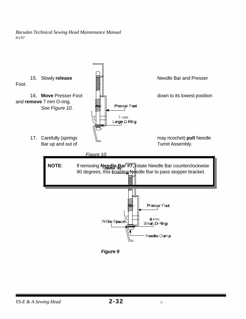
14. Hol d NeedleBar andPresser Foot together and remove needle clamp, white spacer and 6 mm O-ring. See Figure 9.
Barudan Technical Sewing Head Maintenance Manual8/1/97
YS-E & A Sewing Head b2-32
Figure 9
Figure 10
NOTE: If removing Needle Bar #7, rotate Needle Bar counterclockwise90 degrees, this enables Needle Bar to pass stopper bracket.
15. Slowly release Needle Bar and PresserFoot.
16. Move Presser Foot down to its lowest positionand remove 7 mm O-ring.
See Figure 10.
17. Carefully (springs may ricochet) pull NeedleBar up and out of Turret Assembly.
Barudan Technical Sewing Head Maintenance Manual8/1/97
2-33YS-E & A Sewing Head Macpherson Meistergram
Figure 11
Figure 12
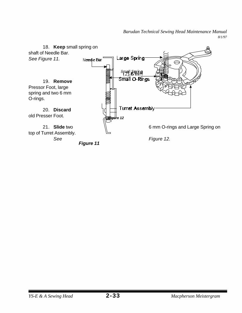
18. Keep small spring onshaft of Needle Bar. See Figure 11.
19. RemovePressor Foot, largespring and two 6 mmO-rings.
20. Discardold Presser Foot.
21. Slide two 6 mm O-rings and Large Spring ontop of Turret Assembly.
See Figure 12.
Barudan Technical Sewing Head Maintenance Manual8/1/97
YS-E & A Sewing Head b2-34
Figure 13
Figure 14
NOTE: If inserting Needle Bar #7 reinstall in same manner it wasremoved in Step 17's Note.
Figure 15
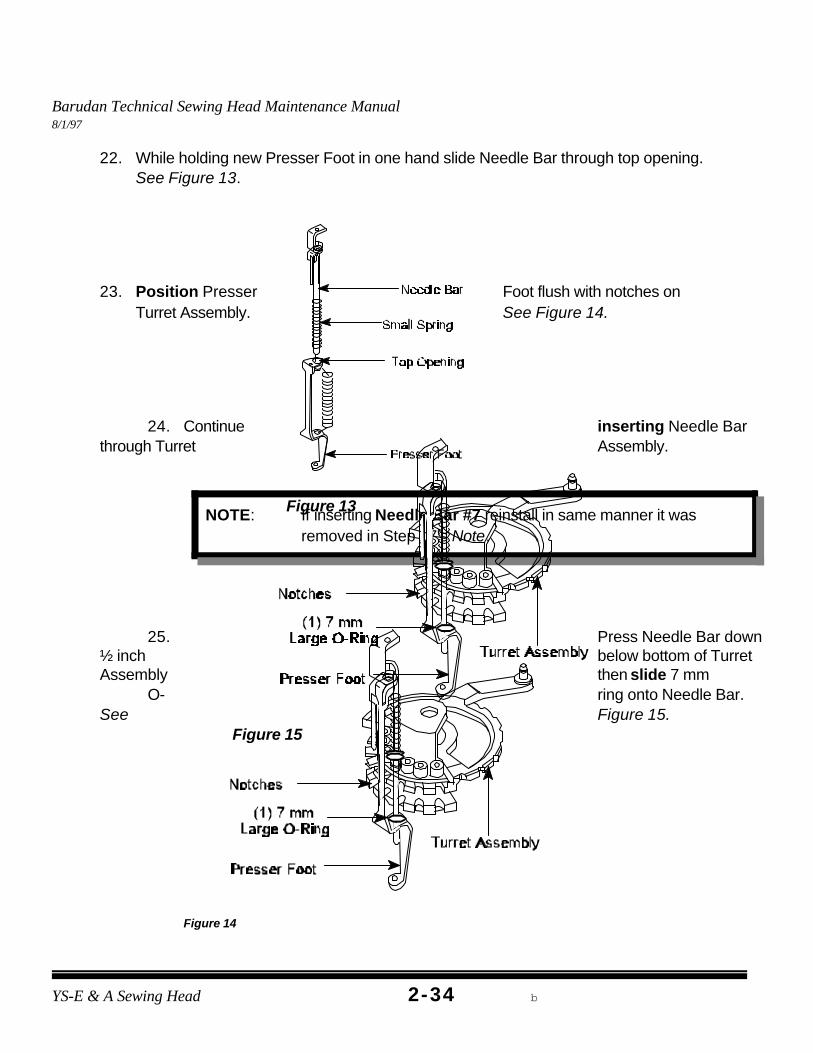
22. While holding new Presser Foot in one hand slide Needle Bar through top opening. See Figure 13.
23. Position Presser Foot flush with notches onTurret Assembly. See Figure 14.
25. Press Needle Bar down½ inch below bottom of TurretAssembly then slide 7 mm
O- ring onto Needle Bar. See Figure 15.
Barudan Technical Sewing Head Maintenance Manual8/1/97
2-35YS-E & A Sewing Head Macpherson Meistergram
Figure 16
Figure 17Figure 18
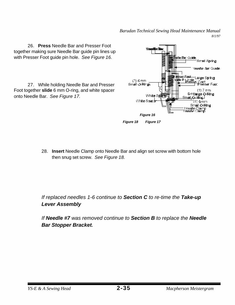
26. Press Needle Bar and Presser Foottogether making sure Needle Bar guide pin lines upwith Presser Foot guide pin hole. See Figure 16.
27. While holding Needle Bar and PresserFoot together slide 6 mm O-ring, and white spaceronto Needle Bar. See Figure 17.
28. Insert Needle Clamp onto Needle Bar and align set screw with bottom holethen snug set screw. See Figure 18.
If replaced needles 1-6 continue to Section C to re-time the Take-upLever Assembly
If Needle #7 was removed continue to Section B to replace the NeedleBar Stopper Bracket.
Barudan Technical Sewing Head Maintenance Manual8/1/97
YS-E & A Sewing Head b2-36
Figure 19
Figure 20
Figure 21
B. NEEDLE BAR STOPPER BRACKETREPLACEMENT
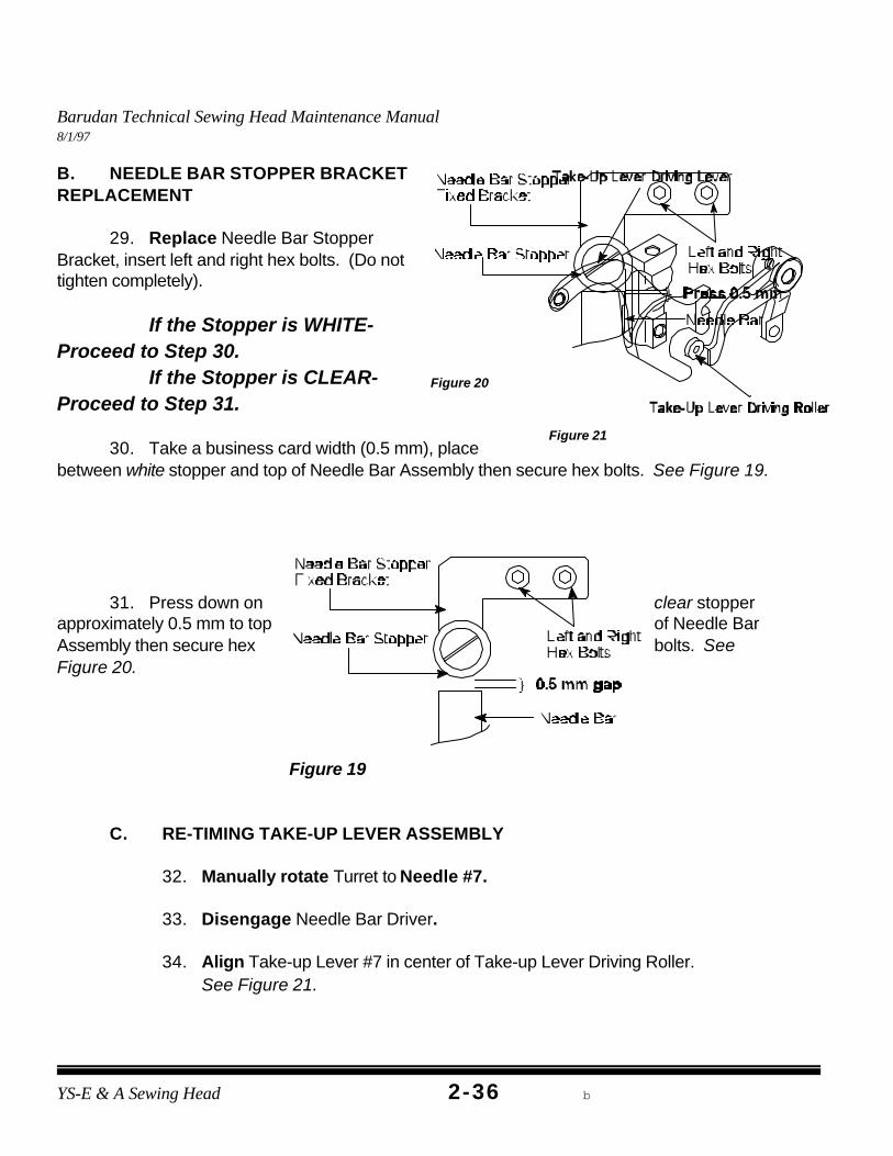
29. Replace Needle Bar StopperBracket, insert left and right hex bolts. (Do nottighten completely).
If the Stopper is WHITE-Proceed to Step 30.
If the Stopper is CLEAR-Proceed to Step 31.
30. Take a business card width (0.5 mm), placebetween white stopper and top of Needle Bar Assembly then secure hex bolts. See Figure 19.
31. Press down on clear stopperapproximately 0.5 mm to top of Needle BarAssembly then secure hex bolts. SeeFigure 20.
C. RE-TIMING TAKE-UP LEVER ASSEMBLY
32. Manually rotate Turret to Needle #7.
33. Disengage Needle Bar Driver.
34. Align Take-up Lever #7 in center of Take-up Lever Driving Roller. See Figure 21.
Barudan Technical Sewing Head Maintenance Manual8/1/97
2-37YS-E & A Sewing Head Macpherson Meistergram
35. Engage Needle Bar Driver.
36. Rotate gangshaft so Take-up Lever is in its lowest position. (Using degree wheelrotate to 115 degrees).
Barudan Technical Sewing Head Maintenance Manual8/1/97
YS-E & A Sewing Head b2-38
Figure 22
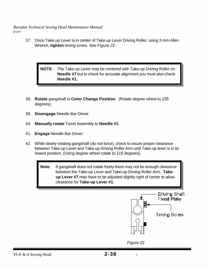
NOTE: The Take-up Lever may be centered with Take-up Driving Roller onNeedle #7 but to check for accurate alignment you must also checkNeedle #1.
Note: If gangshaft does not rotate freely there may not be enough clearancebetween the Take-up Lever and Take-up Driving Roller Arm. Take-up Lever #7 may have to be adjusted slightly right of center to allowclearance for Take-up Lever #1.
37. Once Take-up Lever is in center of Take-up Lever Driving Roller, using 3 mm AllenWrench, tighten timing screw. See Figure 22.
38. Rotate gangshaft to Color Change Position. (Rotate degree wheel to 235degrees).
39. Disengage Needle Bar Driver.
40. Manually rotate Turret Assembly to Needle #1.
41. Engage Needle Bar Driver.
42. While slowly rotating gangshaft (do not force), check to insure proper clearancebetween Take-up Lever and Take-up Driving Roller Arm until Take-up lever is in itslowest position. (Using degree wheel rotate to 115 degrees).
Barudan Technical Sewing Head Maintenance Manual8/1/97
2-39YS-E & A Sewing Head Macpherson Meistergram
Figure 23
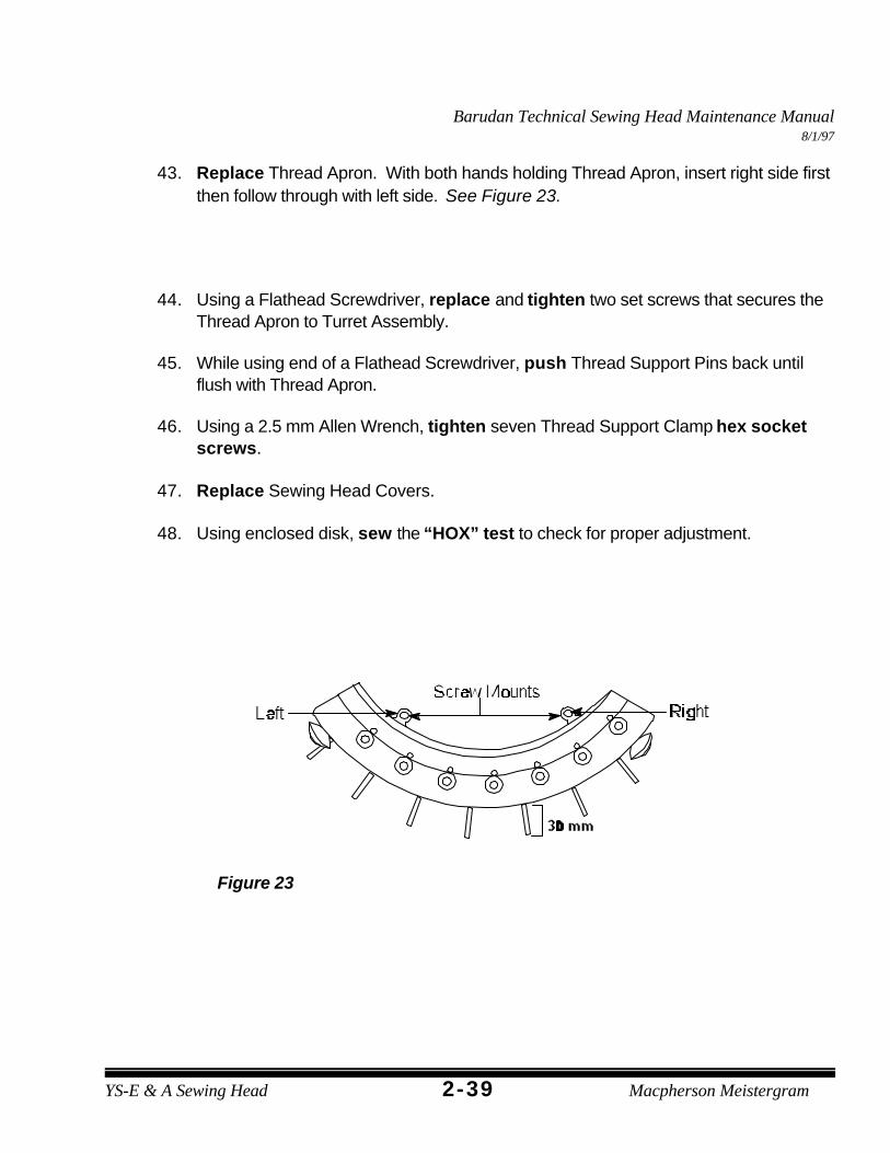
43. Replace Thread Apron. With both hands holding Thread Apron, insert right side firstthen follow through with left side. See Figure 23.
44. Using a Flathead Screwdriver, replace and tighten two set screws that secures theThread Apron to Turret Assembly.
45. While using end of a Flathead Screwdriver, push Thread Support Pins back untilflush with Thread Apron.
46. Using a 2.5 mm Allen Wrench, tighten seven Thread Support Clamp hex socketscrews.
47. Replace Sewing Head Covers.
48. Using enclosed disk, sew the “HOX” test to check for proper adjustment.
Barudan Technical Sewing Head Maintenance Manual8/1/97
YS-E & A Sewing Head b2-40
TOOLS NEEDED1.5 mm Allen Wrench
3 mm T-Handle Allen WrenchNew Take-Up Lever (s)
Figure 1
Figure 2
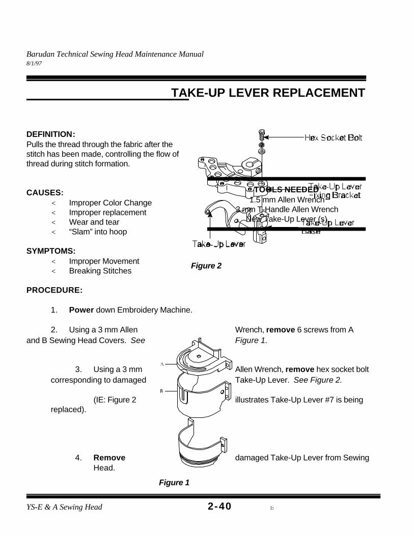
TAKE-UP LEVER REPLACEMENT
DEFINITION:Pulls the thread through the fabric after thestitch has been made, controlling the flow ofthread during stitch formation.
CAUSES:< Improper Color Change< Improper replacement< Wear and tear< “Slam” into hoop
SYMPTOMS:< Improper Movement< Breaking Stitches
PROCEDURE:
1. Power down Embroidery Machine.
2. Using a 3 mm Allen Wrench, remove 6 screws from Aand B Sewing Head Covers. See Figure 1.
3. Using a 3 mm Allen Wrench, remove hex socket boltcorresponding to damaged Take-Up Lever. See Figure 2.
(IE: Figure 2 illustrates Take-Up Lever #7 is beingreplaced).
4. Remove damaged Take-Up Lever from SewingHead.
Barudan Technical Sewing Head Maintenance Manual8/1/97
2-41YS-E & A Sewing Head Macpherson Meistergram
Figure 3
Figure 4
Figure 5
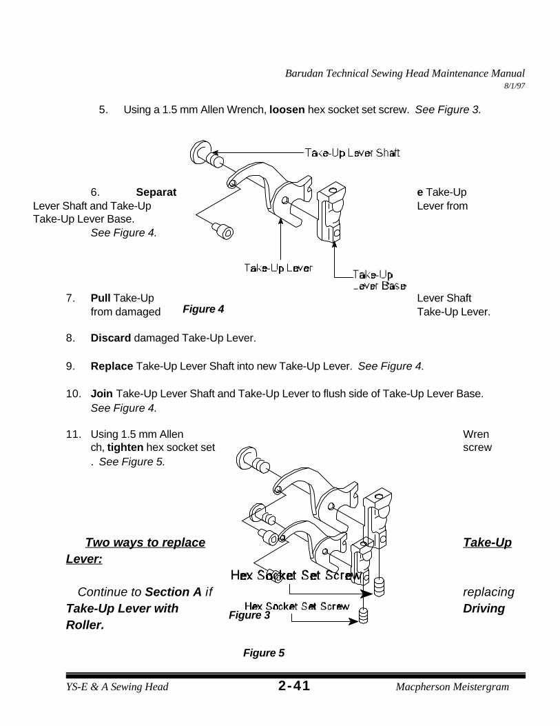
5. Using a 1.5 mm Allen Wrench, loosen hex socket set screw. See Figure 3.
6. Separat e Take-UpLever Shaft and Take-Up Lever fromTake-Up Lever Base.
See Figure 4.
7. Pull Take-Up Lever Shaftfrom damaged Take-Up Lever.
8. Discard damaged Take-Up Lever.
9. Replace Take-Up Lever Shaft into new Take-Up Lever. See Figure 4.
10. Join Take-Up Lever Shaft and Take-Up Lever to flush side of Take-Up Lever Base. See Figure 4.
11. Using 1.5 mm Allen Wrench, tighten hex socket set screw. See Figure 5.
Two ways to replace Take-UpLever:
Continue to Section A if replacingTake-Up Lever with DrivingRoller.
Barudan Technical Sewing Head Maintenance Manual8/1/97
YS-E & A Sewing Head b2-42
Figure 6
or
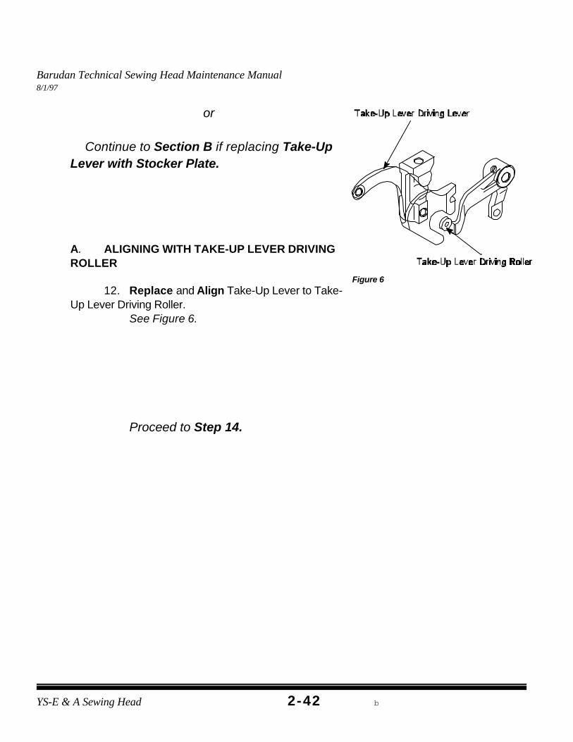
Continue to Section B if replacing Take-UpLever with Stocker Plate.
A. ALIGNING WITH TAKE-UP LEVER DRIVINGROLLER
12. Replace and Align Take-Up Lever to Take-Up Lever Driving Roller.
See Figure 6.
Proceed to Step 14.
Barudan Technical Sewing Head Maintenance Manual8/1/97
2-43YS-E & A Sewing Head Macpherson Meistergram
Figure 7
Figure 8
TOOLS NEEDED2 mm Allen Wrench
3 mm T-Handle Allen WrenchFlathead ScrewdriverNeedle Screwdriver
New Needle Bar DriverFlashlight
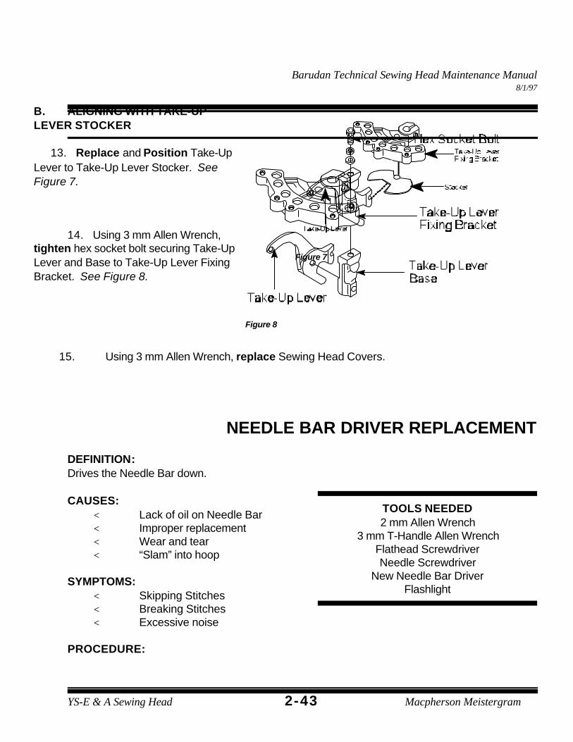
B. ALIGNING WITH TAKE-UPLEVER STOCKER
13. Replace and Position Take-UpLever to Take-Up Lever Stocker. SeeFigure 7.
14. Using 3 mm Allen Wrench,tighten hex socket bolt securing Take-UpLever and Base to Take-Up Lever FixingBracket. See Figure 8.
15. Using 3 mm Allen Wrench, replace Sewing Head Covers.
NEEDLE BAR DRIVER REPLACEMENT
DEFINITION:Drives the Needle Bar down.
CAUSES:< Lack of oil on Needle Bar< Improper replacement< Wear and tear< “Slam” into hoop
Barudan Technical Sewing Head Maintenance Manual8/1/97
YS-E & A Sewing Head b2-44
Figure 1
Figure 2
Figure 3
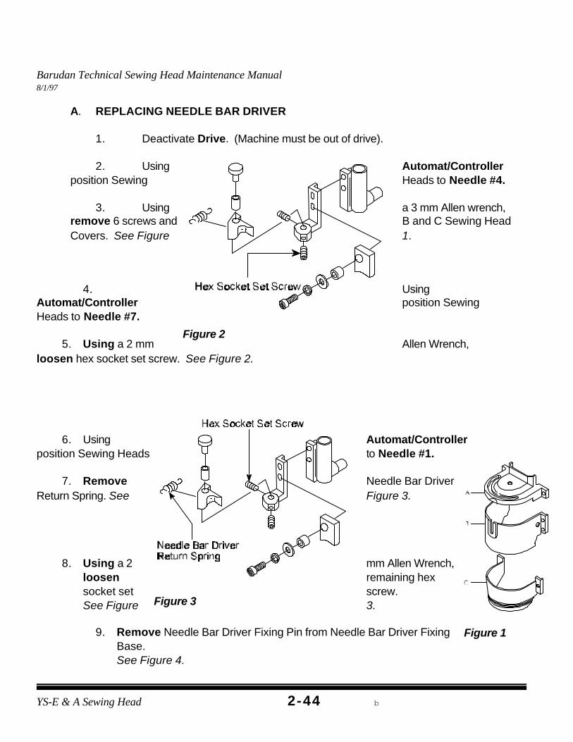
A. REPLACING NEEDLE BAR DRIVER
1. Deactivate Drive. (Machine must be out of drive).
2. Using Automat/Controllerposition Sewing Heads to Needle #4.
3. Using a 3 mm Allen wrench,remove 6 screws and B and C Sewing HeadCovers. See Figure 1.
4. UsingAutomat/Controller position SewingHeads to Needle #7.
5. Using a 2 mm Allen Wrench,loosen hex socket set screw. See Figure 2.
6. Using Automat/Controllerposition Sewing Heads to Needle #1.
7. Remove Needle Bar DriverReturn Spring. See Figure 3.
8. Using a 2 mm Allen Wrench,loosen remaining hexsocket set screw. See Figure 3.
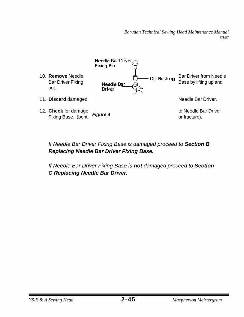
9. Remove Needle Bar Driver Fixing Pin from Needle Bar Driver FixingBase. See Figure 4.
Barudan Technical Sewing Head Maintenance Manual8/1/97
2-45YS-E & A Sewing Head Macpherson Meistergram
Figure 4
10. Remove Needle Bar Driver from NeedleBar Driver Fixing Base by lifting up andout.
11. Discard damaged Needle Bar Driver.
12. Check for damage to Needle Bar DriverFixing Base. (bent or fracture).
If Needle Bar Driver Fixing Base is damaged proceed to Section BReplacing Needle Bar Driver Fixing Base.
If Needle Bar Driver Fixing Base is not damaged proceed to SectionC Replacing Needle Bar Driver.
Barudan Technical Sewing Head Maintenance Manual8/1/97
YS-E & A Sewing Head b2-46
Figure 5
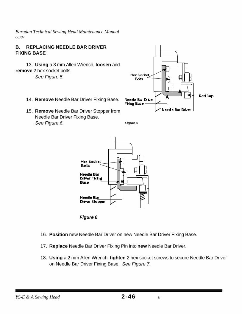
B. REPLACING NEEDLE BAR DRIVERFIXING BASE
13. Using a 3 mm Allen Wrench, loosen andremove 2 hex socket bolts.
See Figure 5.
14. Remove Needle Bar Driver Fixing Base.
15. Remove Needle Bar Driver Stopper fromNeedle Bar Driver Fixing Base. See Figure 6.
Figure 6
16. Position new Needle Bar Driver on new Needle Bar Driver Fixing Base.
17. Replace Needle Bar Driver Fixing Pin into new Needle Bar Driver.
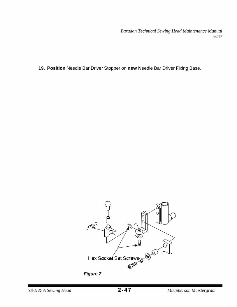
18. Using a 2 mm Allen Wrench, tighten 2 hex socket screws to secure Needle Bar Driveron Needle Bar Driver Fixing Base. See Figure 7.
Barudan Technical Sewing Head Maintenance Manual8/1/97
2-47YS-E & A Sewing Head Macpherson Meistergram
Figure 7
19. Position Needle Bar Driver Stopper on new Needle Bar Driver Fixing Base.
Barudan Technical Sewing Head Maintenance Manual8/1/97
YS-E & A Sewing Head b2-48
Figure 9
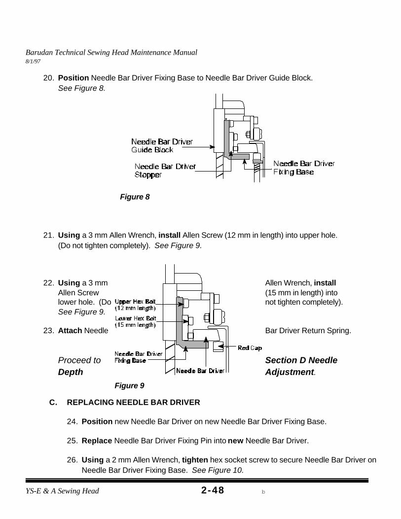
20. Position Needle Bar Driver Fixing Base to Needle Bar Driver Guide Block. See Figure 8.
Figure 8
21. Using a 3 mm Allen Wrench, install Allen Screw (12 mm in length) into upper hole. (Do not tighten completely). See Figure 9.
22. Using a 3 mm Allen Wrench, installAllen Screw (15 mm in length) intolower hole. (Do not tighten completely). See Figure 9.
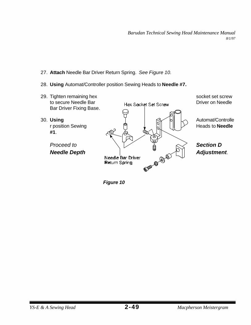
23. Attach Needle Bar Driver Return Spring.
Proceed to Section D NeedleDepth Adjustment.
C. REPLACING NEEDLE BAR DRIVER
24. Position new Needle Bar Driver on new Needle Bar Driver Fixing Base.
25. Replace Needle Bar Driver Fixing Pin into new Needle Bar Driver.
26. Using a 2 mm Allen Wrench, tighten hex socket screw to secure Needle Bar Driver onNeedle Bar Driver Fixing Base. See Figure 10.
Barudan Technical Sewing Head Maintenance Manual8/1/97
2-49YS-E & A Sewing Head Macpherson Meistergram
Figure 10
27. Attach Needle Bar Driver Return Spring. See Figure 10.
28. Using Automat/Controller position Sewing Heads to Needle #7.
29. Tighten remaining hex socket set screwto secure Needle Bar Driver on NeedleBar Driver Fixing Base.
30. Using Automat/Controller position Sewing Heads to Needle#1.
Proceed to Section DNeedle Depth Adjustment.
Barudan Technical Sewing Head Maintenance Manual8/1/97
YS-E & A Sewing Head b2-50
Figure 11
D. NEEDLE DEPTH ADJUSTMENT
31. Using a Flathead Screwdriver, remove throat platescrews.
32. Remove throat plate.
33. Remove bobbin case from Hook Assembly.
34. Using cleaning brush, clean any thread debris orlint from hook area.
35. Remove thread from Needle #1.
36. Using Needle Screwdriver, loosen needle set screw.
37. Remove and discard old needle.
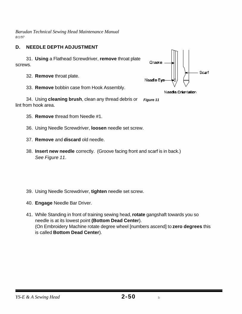
38. Insert new needle correctly. (Groove facing front and scarf is in back.) See Figure 11.
39. Using Needle Screwdriver, tighten needle set screw.
40. Engage Needle Bar Driver.
41. While Standing in front of training sewing head, rotate gangshaft towards you soneedle is at its lowest point (Bottom Dead Center). (On Embroidery Machine rotate degree wheel [numbers ascend] to zero degrees thisis called Bottom Dead Center).
Barudan Technical Sewing Head Maintenance Manual8/1/97
2-51YS-E & A Sewing Head Macpherson Meistergram
Figure 12
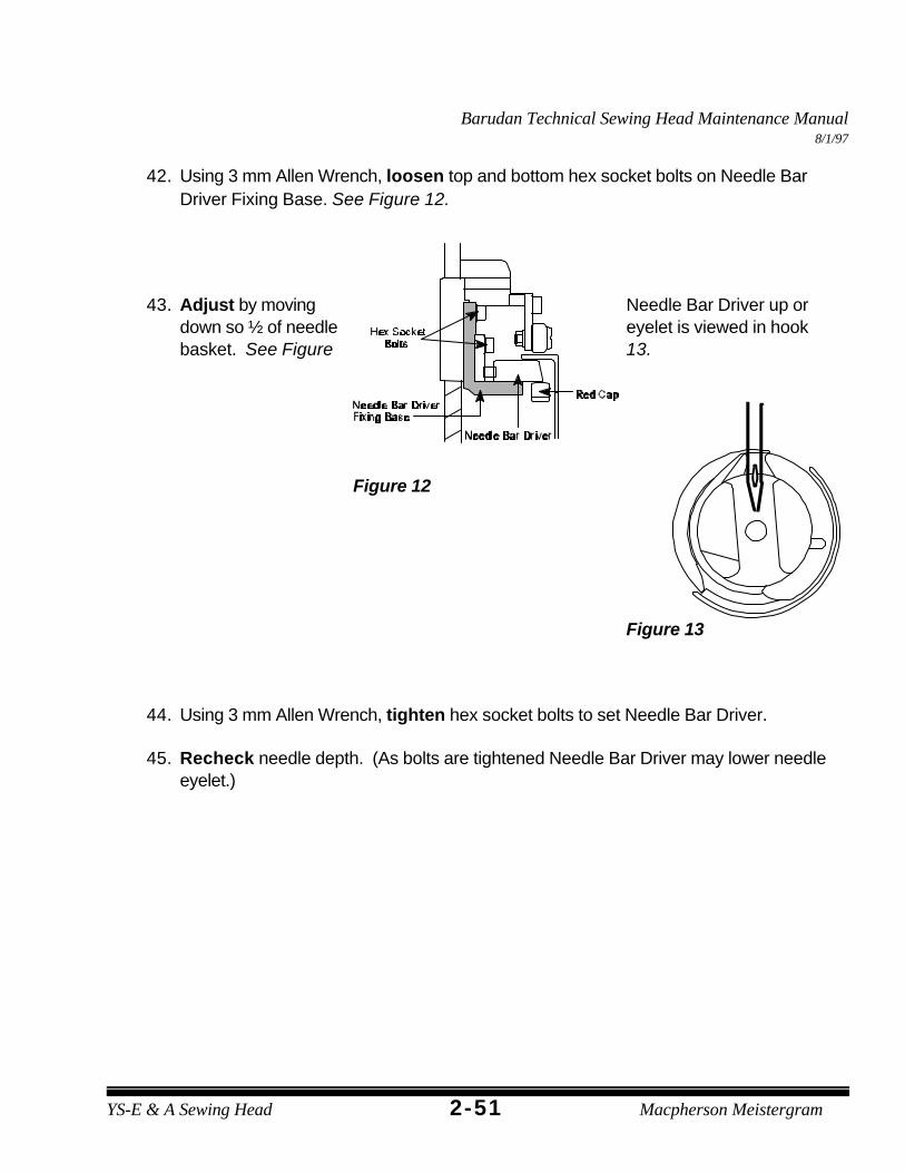
42. Using 3 mm Allen Wrench, loosen top and bottom hex socket bolts on Needle BarDriver Fixing Base. See Figure 12.
43. Adjust by moving Needle Bar Driver up ordown so ½ of needle eyelet is viewed in hookbasket. See Figure 13.
Figure 13
44. Using 3 mm Allen Wrench, tighten hex socket bolts to set Needle Bar Driver.
45. Recheck needle depth. (As bolts are tightened Needle Bar Driver may lower needleeyelet.)
Barudan Technical Sewing Head Maintenance Manual8/1/97
YS-E & A Sewing Head b2-52
46. Rotate gangshaft to Color Change Position. (Rotate degree wheel to 235 degrees)
47. Reinstall throat plate.
48. Using Flathead Screwdriver, tighten throat plate screws.
49. Reinstall bobbin case.
50. Using 3 mm Allen Wrench, replace Sewing Head Covers.
51. Using enclosed disk, sew the “HOX” test to check for proper adjustment.
Barudan Technical Sewing Head Maintenance Manual8/1/97
DEFINITION:The rear bushing allows the bottom shaft to rotate freely without front to back movement, securingthe Hook Assembly. The bushing has an oil pad which allows oil to saturate and lubricate thebottom shaft.
CAUSES:< Lack of oil< Improper replacement< Wear and tear
SYMPTOMS:< Little or no Hook movement< Excessive noise
PROCEDURE:
A. REMOVING REAR BUSHING
1. Power down Embroidery Machine.
2. Disengage Needle Bar Driver.
3. Using Flathead Screwdriver, remove throat plate screws.
4. Remove throat plate.
Barudan Technical Sewing Head Maintenance Manual8/1/97
YS-E & A Sewing Head b2-54
Barudan Technical Sewing Head Maintenance Manual8/1/97
2-55YS-E & A Sewing Head Macpherson Meistergram
Figure 1
5. Using 2 mm Allen Wrench, remove Upper Knife hex bolt (MK 4 trimmer only apply). See Figure 1.
6. Remove Upper Knife (MK 4trimmer only apply). SeeFigure 1.
7. Using Flathead Screwdriver,remove Position Finger screw.
8. Remove Position Finger.
9. Remove Hook Driving Rod fromHook (Fork).
10. Release Hook (Fork). (This allows Hook Assembly to be removed easily).
11. Remove Hook Assembly by loosening three set screws.
12. Remove Hook Assembly.
Barudan Technical Sewing Head Maintenance Manual8/1/97
YS-E & A Sewing Head b2-56
Figure 2
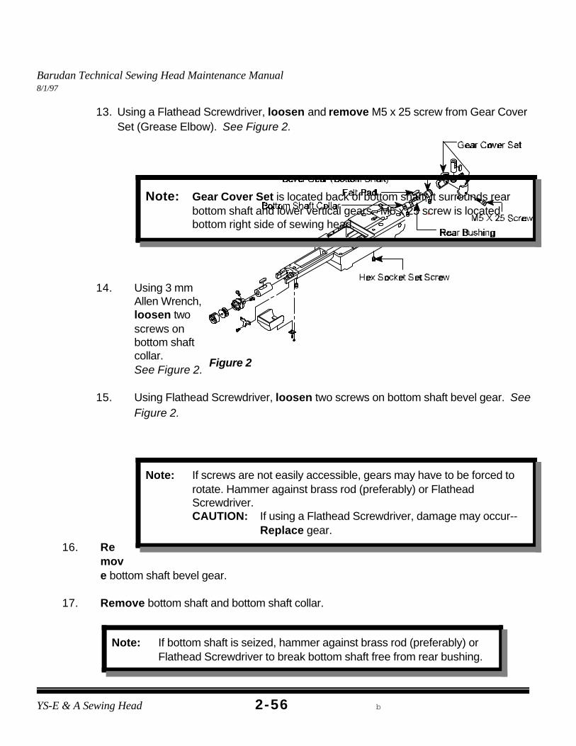
Note: Gear Cover Set is located back of bottom shaft, it surrounds rearbottom shaft and lower vertical gears. M5 x 25 screw is locatedbottom right side of sewing head.
Note: If screws are not easily accessible, gears may have to be forced torotate. Hammer against brass rod (preferably) or FlatheadScrewdriver. CAUTION: If using a Flathead Screwdriver, damage may occur--
Replace gear.
Note: If bottom shaft is seized, hammer against brass rod (preferably) orFlathead Screwdriver to break bottom shaft free from rear bushing.
13. Using a Flathead Screwdriver, loosen and remove M5 x 25 screw from Gear Cover Set (Grease Elbow). See Figure 2.
14. Using 3 mmAllen Wrench,loosen twoscrews onbottom shaftcollar. See Figure 2.
15. Using Flathead Screwdriver, loosen two screws on bottom shaft bevel gear. SeeFigure 2.
16. Remove bottom shaft bevel gear.
17. Remove bottom shaft and bottom shaft collar.
Barudan Technical Sewing Head Maintenance Manual8/1/97
2-57YS-E & A Sewing Head Macpherson Meistergram
Note: CAUTION: Oil Port on bushing must be positioned up with oilrecess facing front. This allows oil to pass through bushing ontobottom shaft.
18. Using 3 mm Allen Wrench, loosen 3 mm Allen screw from bottom rear bushing. (This screw holds bushing in place.)
19. Remove rear bushing by hammering a brass rod against rear side of bushing. (Bushing can only be removed in one direction--forward towards front of sewinghead).
20. Remove felt pad from bushing.
21. Clean felt pad and set aside.
22. Discard bushing.
23. Insert felt pad into new bushing.
24. Using permanent marker, mark both ends of new rear shaft bushing to indicate oilport location.
25. Oil outer bushing for smoother installation.
26. Insert new bushing from front (oil port facing up with oil recess facing front) untilbushing is 5 mm through opposite side of casting.
27. Using permanent marker, mark new bottom shaft end to indicate flat spot.
28. Insert new bottom shaft (marked flat end) through front bushing only.
29. Insert bottom shaft collar (shiny side against rear bushing) onto bottom shaft.
30. Position bevel gear to rear bushing and align holes.
Barudan Technical Sewing Head Maintenance Manual8/1/97
YS-E & A Sewing Head b2-58
Note: Once both gears are meshed and set into place the gangshaftshould rotate in the same manner when gears were apart.
Note: This adjustment is very critical:< Proper Gear Alignment-Gangshaft must rotate smoothly.
Unnoticeable Bottom Shaft front to back movement. .033 mmgap between bushing and bevel gear.
< Tight Gears-Gangshaft binds. Hammer gear in oppositedirection until gangshaft achieves the Proper Gear Alignment.
< Loose Gears-Bottom shaft has front to back movement and playbetween gears. Hammer bushing until achieving Proper GearAlignment .
31. Continue inserting bottom shaft through rear bushing and bevel gear until bottomshaft protrudes 2 mm.
32. With gears apart rotate gangshaft (degree wheel). Gangshaft should rotatesmoothly.
33. Align one set screw on bevel gear to mark (indicating flat spot) on bottom shaft thenusing Flathead Screwdriver, tighten set screw.
34. Using Flathead Screwdriver, tighten remaining set screw on bevel gear.
35. Position two gears together until teeth mesh .
36. Place brass rod against rear bushing and gently hammer brass rod until a .033 mm gap is between bushing and bevel gear.
Barudan Technical Sewing Head Maintenance Manual8/1/97
2-59YS-E & A Sewing Head Macpherson Meistergram
Figure 3
37. Using 3 mm Allen Wrench, tighten 3 mm Allen screw to secure rear bushing.
38. Position bottom shaft collar against rear bushing.
39. Tighten and secure two screws on bottom shaft collar.
48. Using 2 mm Allen Wrench, insert hex bolt (MK 4 trimmer only apply). (Do not tighten completely).
Barudan Technical Sewing Head Maintenance Manual8/1/97
YS-E & A Sewing Head b2-60
Figure 4
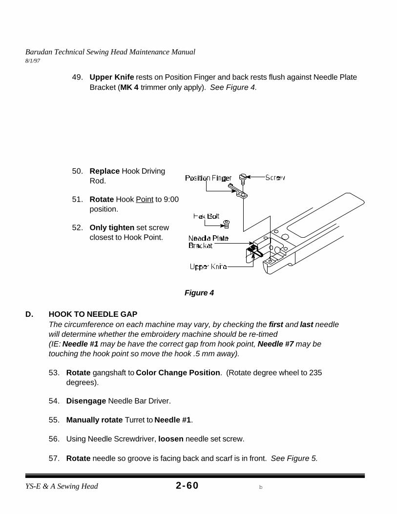
49. Upper Knife rests on Position Finger and back rests flush against Needle PlateBracket (MK 4 trimmer only apply). See Figure 4.
50. Replace Hook DrivingRod.
51. Rotate Hook Point to 9:00position.
52. Only tighten set screwclosest to Hook Point.
D. HOOK TO NEEDLE GAPThe circumference on each machine may vary, by checking the first and last needlewill determine whether the embroidery machine should be re-timed (IE: Needle #1 may be have the correct gap from hook point, Needle #7 may betouching the hook point so move the hook .5 mm away).
53. Rotate gangshaft to Color Change Position. (Rotate degree wheel to 235degrees).
54. Disengage Needle Bar Driver.
55. Manually rotate Turret to Needle #1.
56. Using Needle Screwdriver, loosen needle set screw.
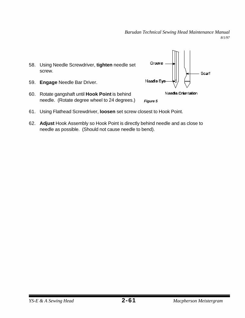
57. Rotate needle so groove is facing back and scarf is in front. See Figure 5.
Barudan Technical Sewing Head Maintenance Manual8/1/97
2-61YS-E & A Sewing Head Macpherson Meistergram
Figure 5
58. Using Needle Screwdriver, tighten needle setscrew.
59. Engage Needle Bar Driver.
60. Rotate gangshaft until Hook Point is behindneedle. (Rotate degree wheel to 24 degrees.)
61. Using Flathead Screwdriver, loosen set screw closest to Hook Point.
62. Adjust Hook Assembly so Hook Point is directly behind needle and as close toneedle as possible. (Should not cause needle to bend).
Barudan Technical Sewing Head Maintenance Manual8/1/97
YS-E & A Sewing Head b2-62
Figure 6
63. Using Flathead Screwdriver, tighten set screwclosest to Hook Point.
64. Rotate gangshaft to Color Change Position.(Rotate degree wheel to 235 degrees).
63. Using Needle Screwdriver, loosen needle setscrew.
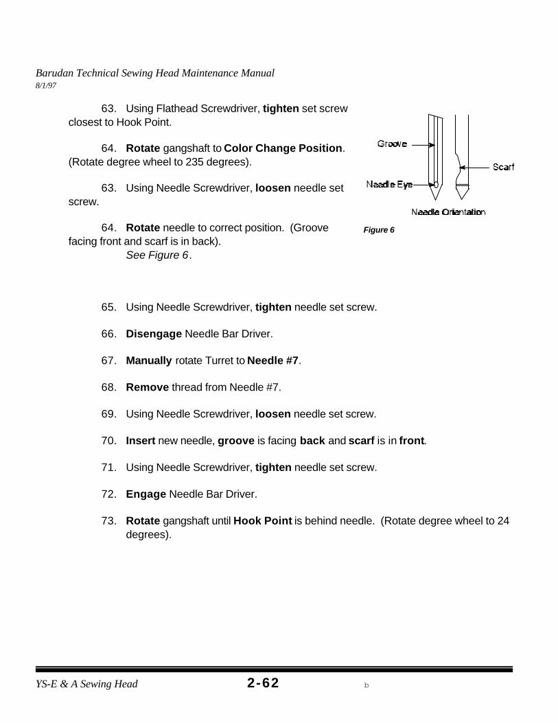
64. Rotate needle to correct position. (Groovefacing front and scarf is in back).
See Figure 6.
65. Using Needle Screwdriver, tighten needle set screw.
66. Disengage Needle Bar Driver.
67. Manually rotate Turret to Needle #7.
68. Remove thread from Needle #7.
69. Using Needle Screwdriver, loosen needle set screw.
70. Insert new needle, groove is facing back and scarf is in front.
71. Using Needle Screwdriver, tighten needle set screw.
72. Engage Needle Bar Driver.
73. Rotate gangshaft until Hook Point is behind needle. (Rotate degree wheel to 24degrees).
Barudan Technical Sewing Head Maintenance Manual8/1/97
2-63YS-E & A Sewing Head Macpherson Meistergram
NOTE: Bobbin thread may not be centered if adjustment is incorrect.
74. Hook Point should be directly behind needle and as close to needle as possible. (Should not cause needle to bend).
If Hook Point causes needle to bend on Needle #7 then adjust Hook Point 0.5 mm away from needle.
75. Using Flathead Screwdriver, tighten two remaining set screws (furthest from hookpoint).
76. Rotate gangshaft to Color Change Position. (Rotate degree wheel to 235degrees).
77. Using Needle Screwdriver, loosen needle set screw.
78. Rotate needle to correct position. (Groove facing front and scarf is in back).
E. POSITION FINGER ADJUSTMENT
79. Engage Needle Bar Driver.
80. Rotate gangshaft until needle reaches it’s lowest point, Bottom Dead center. (Rotate degree wheel to 0 degrees).
81. Using Flathead Screwdriver, loosen Position Finger screw.
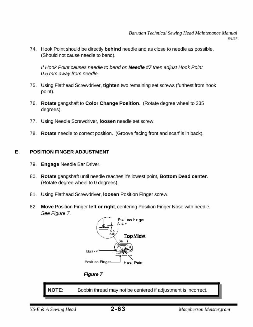
82. Move Position Finger left or right, centering Position Finger Nose with needle. See Figure 7.
Figure 7
Barudan Technical Sewing Head Maintenance Manual8/1/97
YS-E & A Sewing Head b2-64
Figure 8
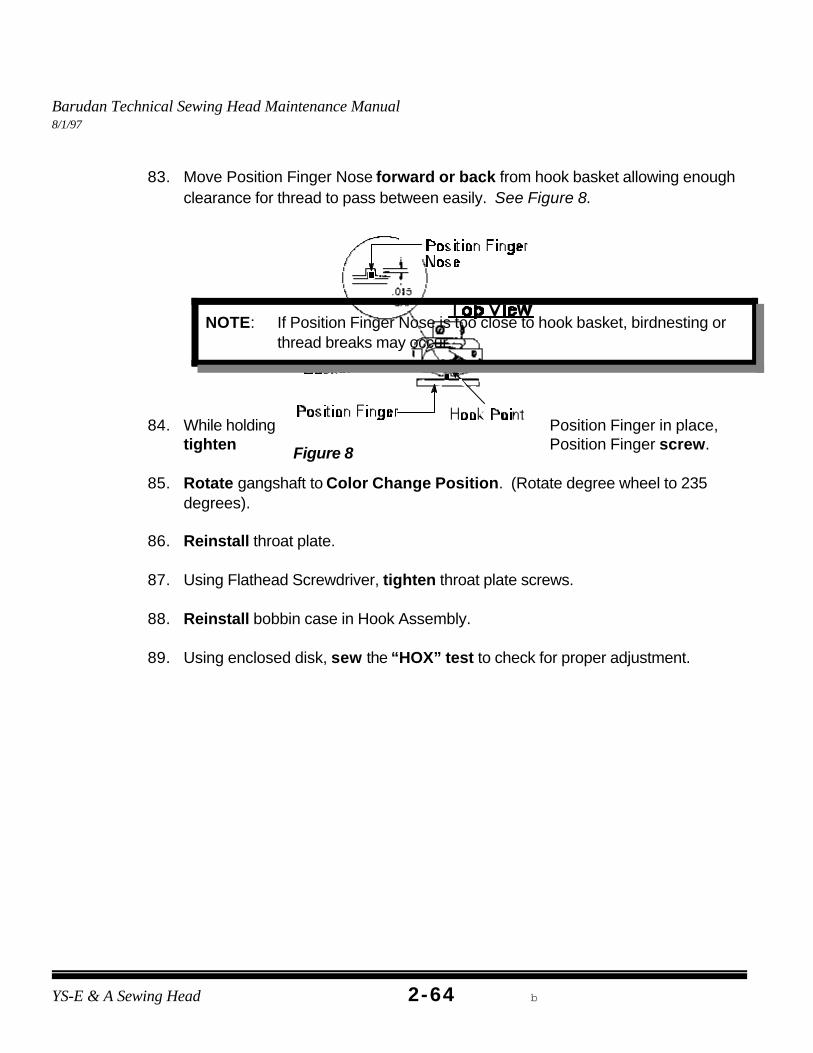
NOTE: If Position Finger Nose is too close to hook basket, birdnesting orthread breaks may occur.
83. Move Position Finger Nose forward or back from hook basket allowing enoughclearance for thread to pass between easily. See Figure 8.
84. While holding Position Finger in place,tighten Position Finger screw.
85. Rotate gangshaft to Color Change Position. (Rotate degree wheel to 235degrees).
86. Reinstall throat plate.
87. Using Flathead Screwdriver, tighten throat plate screws.
88. Reinstall bobbin case in Hook Assembly.
89. Using enclosed disk, sew the “HOX” test to check for proper adjustment.
Barudan Technical Sewing Head Maintenance Manual8/1/97
2-65YS-E & A Sewing Head Macpherson Meistergram
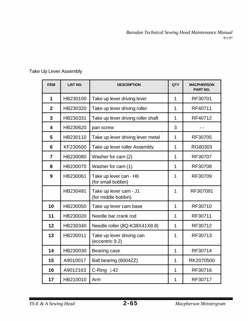
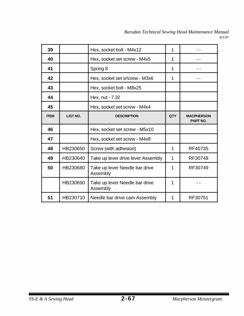
Take Up Lever Assembly
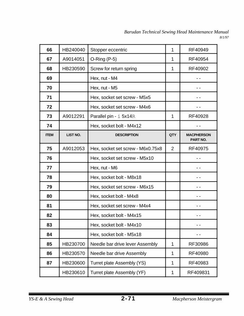
ITEM LIST NO. DESCRIPTION QTY MACPHERSONPART NO.
1 HB230100 Take up lever driving lever 1 RF30701
2 HB230320 Take up lever driving roller 1 RF40711
3 HB230331 Take up lever driving roller shaft 1 RF40712
4 HB230620 pan screw 3 - -
5 HB230110 Take up lever driving lever metal 1 RF30705
6 KF230500 Take up lever roller Assembly 1 RG80303
7 HB230080 Washer for cam (2) 1 RF30707
8 HB230070 Washer for cam (1) 1 RF30708
9 HB230061 Take up lever can - H6(for small bobbin)
1 RF30709
HB230491 Take up lever cam - J1(for middle bobbin)