24
New Features

New Features
2
ETAP Enterprise Solution
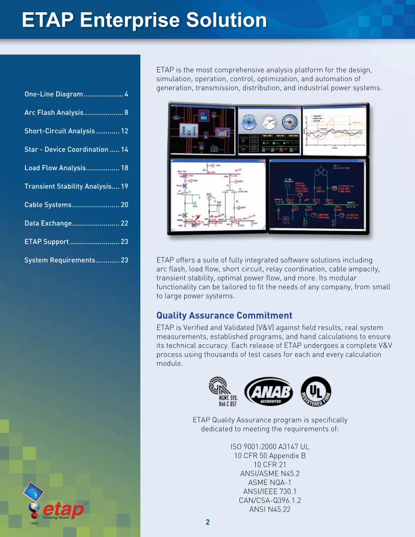
ETAP is the most comprehensive analysis platform for the design, simulation, operation, control, optimization, and automation of generation, transmission, distribution, and industrial power systems.
ETAP offers a suite of fully integrated software solutions including arc flash, load flow, short circuit, relay coordination, cable ampacity, transient stability, optimal power flow, and more. Its modular functionality can be tailored to fit the needs of any company, from small to large power systems.
Quality Assurance CommitmentETAP is Verified and Validated (V&V) against field results, real system measurements, established programs, and hand calculations to ensure its technical accuracy. Each release of ETAP undergoes a complete V&V process using thousands of test cases for each and every calculation module.
One-Line Diagram .................... 4
Arc Flash Analysis .................... 8
Short-Circuit Analysis ............ 12
Star - Device Coordination ..... 14
Load Flow Analysis ................. 18
Transient Stability Analysis .... 19
Cable Systems ........................ 20
Data Exchange ........................ 22
ETAP Support ......................... 23
System Requirements ............ 23
ETAP Quality Assurance program is specifically dedicated to meeting the requirements of:
ISO 9001:2000 A3147 UL10 CFR 50 Appendix B
10 CFR 21ANSI/ASME N45.2
ASME NQA-1ANSI/IEEE 730.1
CAN/CSA-Q396.1.2ANSI N45.22
3
What’s New in ETAP 6.0
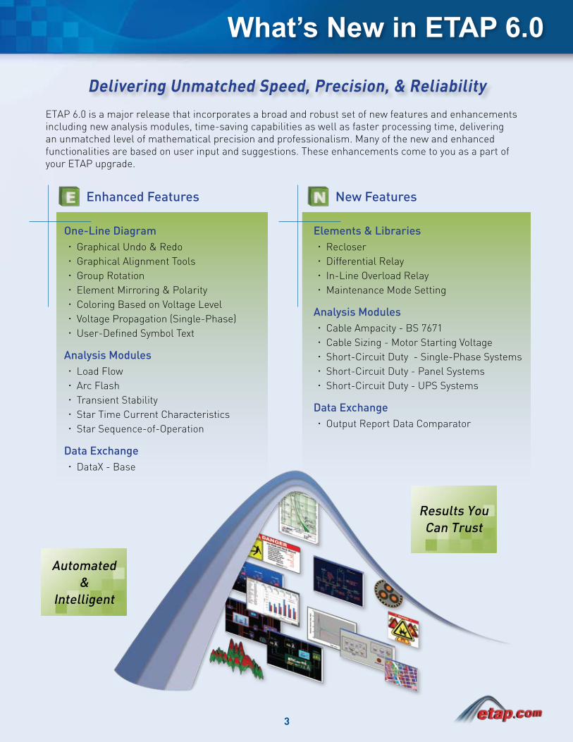
ETAP 6.0 is a major release that incorporates a broad and robust set of new features and enhancements including new analysis modules, time-saving capabilities as well as faster processing time, delivering an unmatched level of mathematical precision and professionalism. Many of the new and enhanced functionalities are based on user input and suggestions. These enhancements come to you as a part of your ETAP upgrade.
Results You Can Trust
Automated &
Intelligent
New FeaturesEnhanced Features
Delivering Unmatched Speed, Precision, & Reliability
Elements & LibrariesRecloser xDifferential Relay xIn-Line Overload Relay xMaintenance Mode Setting x
Analysis ModulesCable Ampacity - BS 7671 xCable Sizing - Motor Starting Voltage xShort-Circuit Duty - Single-Phase Systems xShort-Circuit Duty - Panel Systems xShort-Circuit Duty - UPS Systems x
Data ExchangeOutput Report Data Comparator x
One-Line DiagramGraphical Undo & Redo xGraphical Alignment Tools xGroup Rotation xElement Mirroring & Polarity xColoring Based on Voltage Level xVoltage Propagation (Single-Phase) xUser-Defined Symbol Text x
Analysis ModulesLoad Flow xArc Flash xTransient Stability xStar Time Current Characteristics xStar Sequence-of-Operation x
Data ExchangeDataX - Base x
4
One-Line Diagram
ETAP One-Line Diagram is a user-friendly interface for creating and managing the network database used for schematic network visualization. Using features such as the intelligent one-line diagram, multi-level nesting of sub-systems, multi-color symbols, interfaces for management of switching devices, and a unique multi-dimensional database you can interactively model, monitor, and manage the electrical network as well as execute simulation scenarios and analyze their results in a simple and intuitive manner.
ETAP 6.0 adds an extensive list of new features to the intelligent one-line diagram, propelling day-to-day system modeling and design tasks to a new level of speed, ease, and accuracy than ever before.
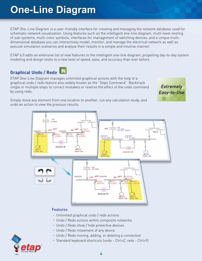
Graphical Undo / RedoETAP One-Line Diagram manages unlimited graphical actions with the help of a graphical undo / redo feature also widely known as the “Oops Command”. Backtrack single or multiple steps to correct mistakes or reverse the effect of the undo command by using redo.
Simply move any element from one location to another, run any calculation study, and undo an action to view the previous results.
FeaturesUnlimited graphical undo / redo actions xUndo / Redo actions within composite networks xUndo / Redo show / hide protective devices xUndo / Redo movement of any device xUndo / Redo moving, adding, or deleting a connection xStandard keyboard shortcuts (undo - Ctrl+Z, redo - Ctrl+Y) x
Extremely Easy-to-Use
5
One-Line Diagram
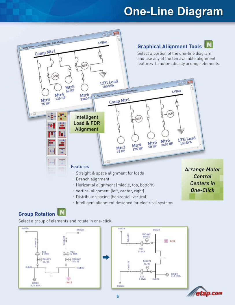
Graphical Alignment ToolsSelect a portion of the one-line diagram and use any of the ten available alignment features to automatically arrange elements.
Group RotationSelect a group of elements and rotate in one-click.
FeaturesStraight & space alignment for loads xBranch alignment xHorizontal alignment (middle, top, bottom) xVertical alignment (left, center, right) xDistribute spacing (horizontal, vertical) xIntelligent alignment designed for electrical systems x
Arrange Motor Control
Centers in One-Click
6
One-Line Diagram
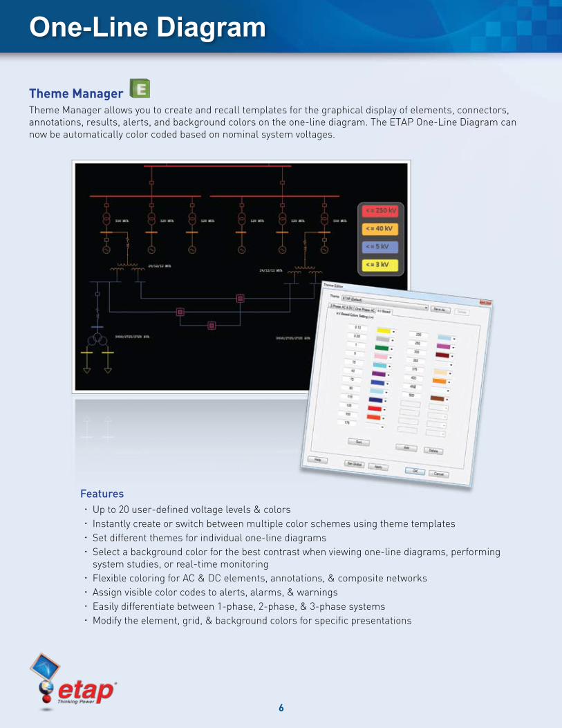
Theme Manager Theme Manager allows you to create and recall templates for the graphical display of elements, connectors, annotations, results, alerts, and background colors on the one-line diagram. The ETAP One-Line Diagram can now be automatically color coded based on nominal system voltages.
FeaturesUp to 20 user-defined voltage levels & colors xInstantly create or switch between multiple color schemes using theme templates xSet different themes for individual one-line diagrams xSelect a background color for the best contrast when viewing one-line diagrams, performing xsystem studies, or real-time monitoringFlexible coloring for AC & DC elements, annotations, & composite networks xAssign visible color codes to alerts, alarms, & warnings xEasily differentiate between 1-phase, 2-phase, & 3-phase systems xModify the element, grid, & background colors for specific presentations x
7
One-Line Diagram
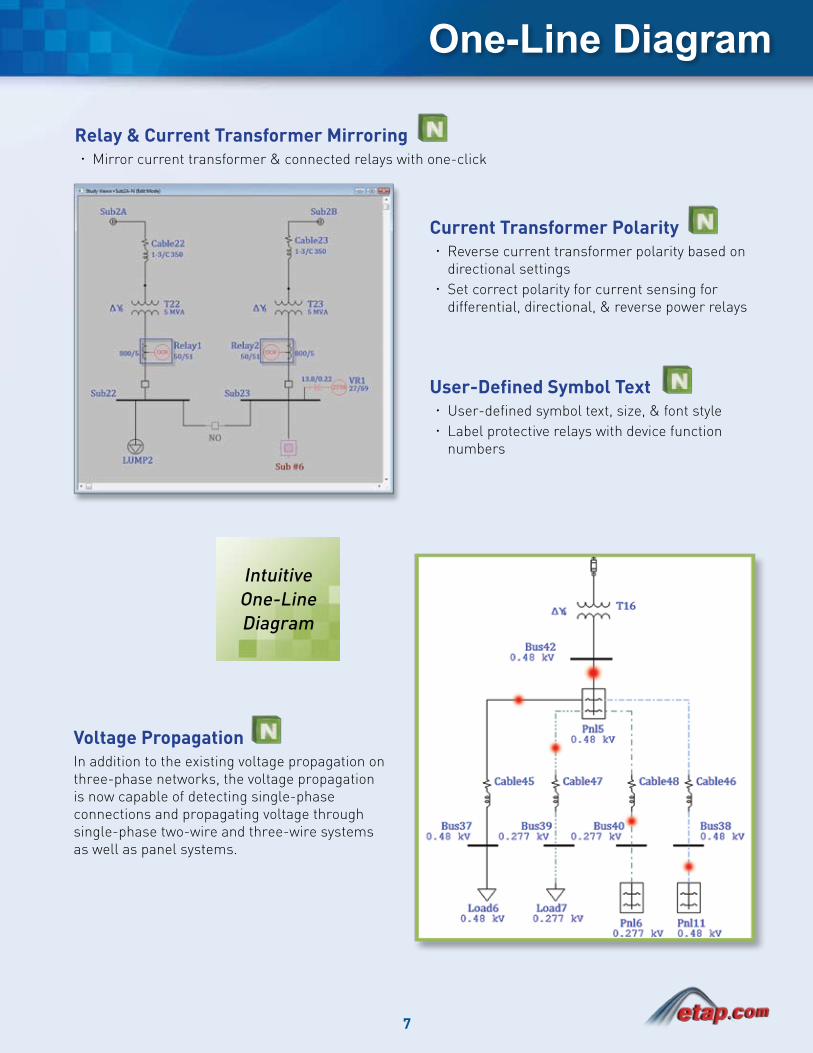
Relay & Current Transformer MirroringMirror current transformer & connected relays with one-click x
Current Transformer PolarityReverse current transformer polarity based on xdirectional settingsSet correct polarity for current sensing for xdifferential, directional, & reverse power relays
User-Defined Symbol TextUser-defined symbol text, size, & font style xLabel protective relays with device function xnumbers
Voltage PropagationIn addition to the existing voltage propagation on three-phase networks, the voltage propagation is now capable of detecting single-phase connections and propagating voltage through single-phase two-wire and three-wire systems as well as panel systems.
IntuitiveOne-LineDiagram

8
Arc Flash Analysis
Enhance Personnel Safety ETAP 6.0 brings you new and enhanced capabilities which allow for faster and easier performance of arc flash hazard analysis. Identify and analyze high risk arc flash areas in your electrical system with greater flexibility by simulating various incident energy mitigation methods.
Arc Flash is a completely integrated module that solves multiple scenarios to determine worst case incident energy levels and it also produces professional reports and high quality arc flash labels at a press of a button.
The Most Comprehensive
Arc Flash HazardAssessment
Solution
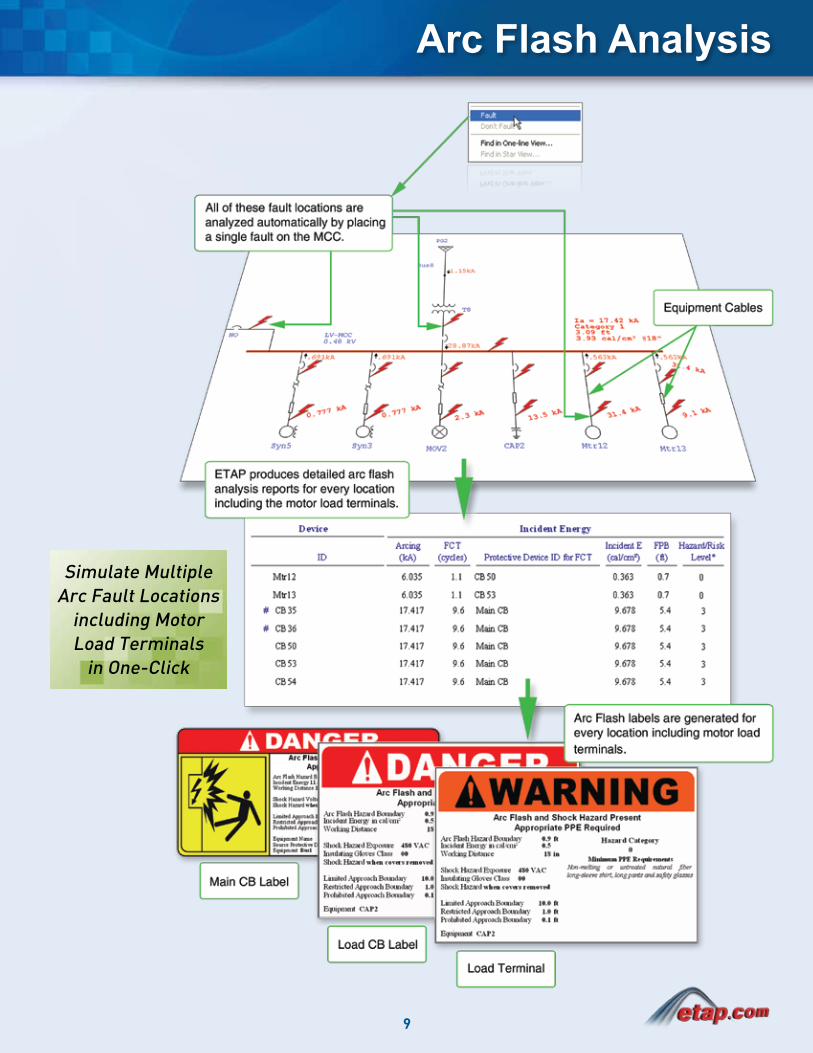
Load Terminal Arc Fault ETAP Arc Flash Analysis provides the flexibility to analyze hundreds of possible arc fault locations without the need for additional buses. This simple “One-Click & Fault” performs arc fault analysis at load terminals without the need for terminal buses or nodes.
Produce detailed analysis reports for every faulted location xAutomatically generate arc flash labels for every incoming main circuit breaker cubicle, load circuit xbreaker, & motor starter bucketAutomatically generate arc flash labels for every load terminal point including induction motors, xsynchronous motors, capacitor banks, & static loadsEvaluates incident energy for devices equipped with maintenance mode setting x
IEEE 1584a-2004 method xNFPA 70E-2000 & 2004 methods xCubic box & open air calculations xIntegrated with ANSI & IEC Short-Circuit xIntegrated with Star device coordination x
9
Arc Flash Analysis
Simulate MultipleArc Fault Locations
including Motor Load Terminals
in One-Click
10
Arc Flash Analysis
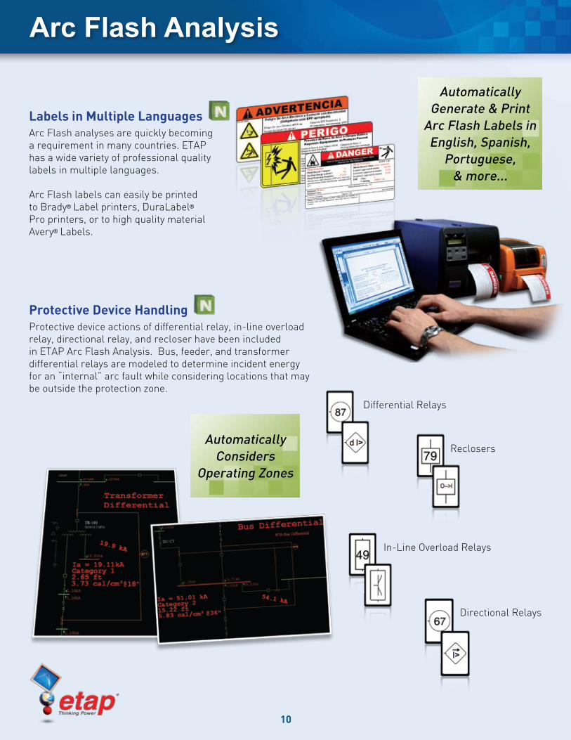
Labels in Multiple Languages Arc Flash analyses are quickly becoming a requirement in many countries. ETAP has a wide variety of professional quality labels in multiple languages.
Arc Flash labels can easily be printed to Brady® Label printers, DuraLabel® Pro printers, or to high quality material Avery® Labels.
Automatically Considers
Operating Zones
Automatically Generate & Print
Arc Flash Labels in English, Spanish,
Portuguese, & more...
Protective Device HandlingProtective device actions of differential relay, in-line overload relay, directional relay, and recloser have been included in ETAP Arc Flash Analysis. Bus, feeder, and transformer differential relays are modeled to determine incident energy for an “internal” arc fault while considering locations that may be outside the protection zone.
Differential Relays
In-Line Overload Relays
Reclosers
Directional Relays
11
Arc Flash Analysis
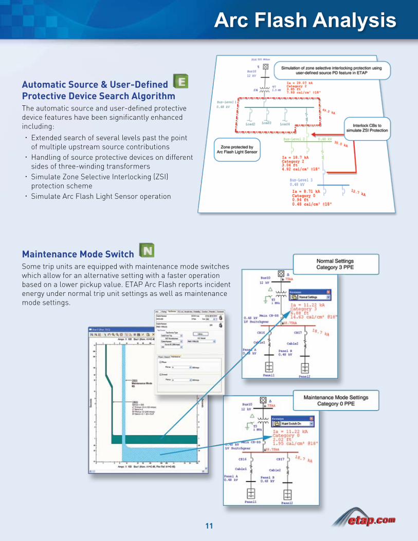
Maintenance Mode SwitchSome trip units are equipped with maintenance mode switches which allow for an alternative setting with a faster operation based on a lower pickup value. ETAP Arc Flash reports incident energy under normal trip unit settings as well as maintenance mode settings.
Automatic Source & User-Defined Protective Device Search AlgorithmThe automatic source and user-defined protective device features have been significantly enhanced including:
Extended search of several levels past the point xof multiple upstream source contributionsHandling of source protective devices on different xsides of three-winding transformersSimulate Zone Selective Interlocking (ZSI) xprotection schemeSimulate Arc Flash Light Sensor operation x
12
UPS SystemsPanel Systems
Multi-Phase Systems
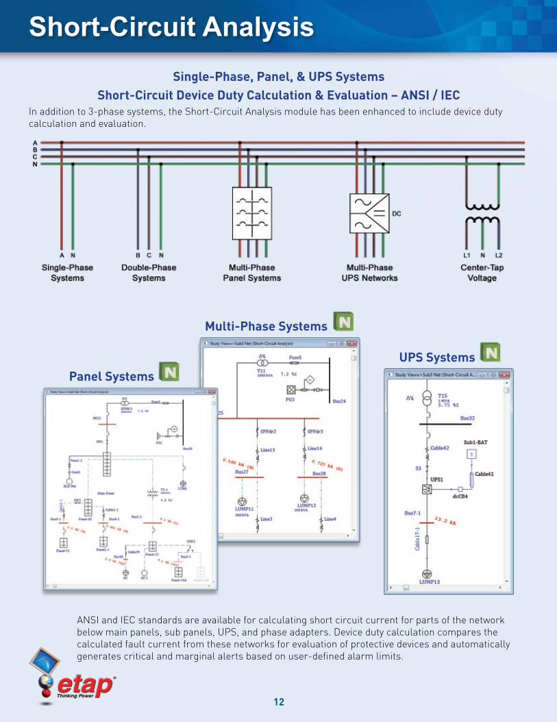
Short-Circuit AnalysisSingle-Phase, Panel, & UPS Systems
Short-Circuit Device Duty Calculation & Evaluation – ANSI / IECIn addition to 3-phase systems, the Short-Circuit Analysis module has been enhanced to include device duty calculation and evaluation.
ANSI and IEC standards are available for calculating short circuit current for parts of the network below main panels, sub panels, UPS, and phase adapters. Device duty calculation compares the calculated fault current from these networks for evaluation of protective devices and automatically generates critical and marginal alerts based on user-defined alarm limits.
13
Short-Circuit Analysis
Benefits of Equipment Cables for LoadsEliminate the need for adding cables (load feeder) & load terminal buses to one-line diagrams xFaster & easier system modeling xCleaner (less cluttered) one-line diagrams xReduce bus numbers (MCC with hundreds of loads is modeled with only one bus) xAutomatic cable sizing based on normal load, motor starting voltage drop, ampacity, & short circuit xrequirementsDisplay results of loading, voltage drop, & load terminal voltage based on bus or load rated voltage on one-line xdiagramsLoad Equipment Cables apply to induction motors, synchronous motors, capacitor banks, static loads, motor xoperated valves, & others with multiple quantitiesDisplay & reporting of the load terminal fault currents under maximum, 1 ½ - 4 cycle, & minimum conditions xfor three-phase, double-phase, & single-phase loads on the one-line diagram
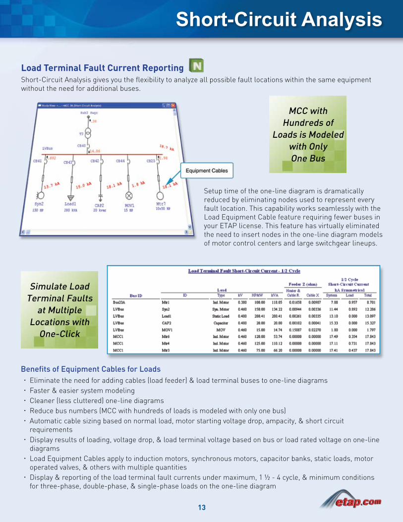
Load Terminal Fault Current ReportingShort-Circuit Analysis gives you the flexibility to analyze all possible fault locations within the same equipment without the need for additional buses.
Setup time of the one-line diagram is dramatically reduced by eliminating nodes used to represent every fault location. This capability works seamlessly with the Load Equipment Cable feature requiring fewer buses in your ETAP license. This feature has virtually eliminated the need to insert nodes in the one-line diagram models of motor control centers and large switchgear lineups.
Simulate Load Terminal Faults
at Multiple Locations with
One-Click
MCC with Hundreds of
Loads is Modeled with OnlyOne Bus
14
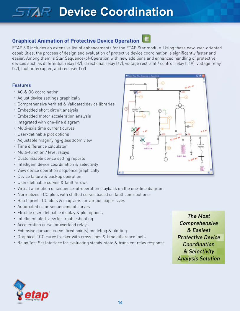
Graphical Animation of Protective Device OperationETAP 6.0 includes an extensive list of enhancements for the ETAP Star module. Using these new user-oriented capabilities, the process of design and evaluation of protective device coordination is significantly faster and easier. Among them is Star Sequence-of-Operation with new additions and enhanced handling of protective devices such as differential relay (87), directional relay (67), voltage restraint / control relay (51V), voltage relay (27), fault interrupter, and recloser (79).
FeaturesAC & DC coordination xAdjust device settings graphically xComprehensive Verified & Validated device libraries xEmbedded short circuit analysis xEmbedded motor acceleration analysis xIntegrated with one-line diagram xMulti-axis time current curves xUser-definable plot options xAdjustable magnifying-glass zoom view xTime difference calculator xMulti-function / level relays xCustomizable device setting reports xIntelligent device coordination & selectivity xView device operation sequence graphically xDevice failure & backup operation xUser-definable curves & fault arrows xVirtual animation of sequence-of-operation playback on the one-line diagram xNormalized TCC plots with shifted curves based on fault contributions xBatch print TCC plots & diagrams for various paper sizes xAutomated color sequencing of curves xFlexible user-definable display & plot options xIntelligent alert view for troubleshooting xAcceleration curve for overload relays xExtensive damage curve (fixed points) modeling & plotting xGraphical TCC curve tracker with cross lines & time difference tools xRelay Test Set Interface for evaluating steady-state & transient relay response x
The Most Comprehensive
& Easiest Protective Device
Coordination & Selectivity
Analysis Solution
Device Coordination
15
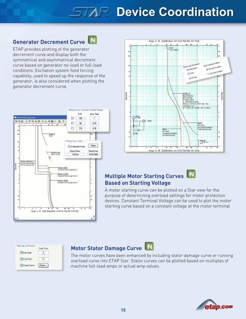
Generator Decrement CurveETAP provides plotting of the generator decrement curve and display both the symmetrical and asymmetrical decrement curve based on generator no-load or full-load conditions. Excitation system field forcing capability, used to speed up the response of the generator, is also considered when plotting the generator decrement curve.
Multiple Motor Starting Curves Based on Starting VoltageA motor starting curve can be plotted on a Star view for the purpose of determining overload settings for motor protection devices. Constant Terminal Voltage can be used to plot the motor starting curve based on a constant voltage at the motor terminal.
Motor Stator Damage CurveThe motor curves have been enhanced by including stator damage curve or running overload curve into ETAP Star. Stator curves can be plotted based on multiples of machine full-load amps or actual amp values.
Device Coordination
16
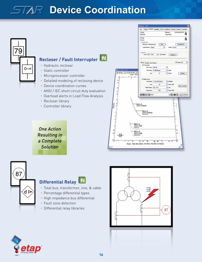
Recloser / Fault InterrupterHydraulic recloser xStatic controller xMicroprocessor controller xDetailed modeling of reclosing device xDevice coordination curves xANSI / IEC short circuit duty evaluation xOverload alerts in Load Flow Analysis xRecloser library xController library x
Differential RelayTotal bus, transformer, line, & cable xPercentage differential types xHigh impedance bus differential xFault zone detection xDifferential relay libraries x
One Action Resulting in a Complete
Solution
Device Coordination
17
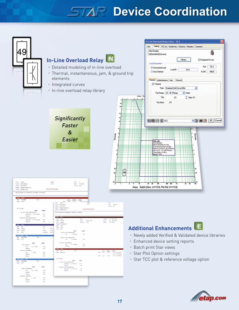
In-Line Overload RelayDetailed modeling of in-line overload xThermal, instantaneous, jam, & ground trip xelementsIntegrated curves xIn-line overload relay library x
SignificantlyFaster
&Easier
Additional EnhancementsNewly added Verified & Validated device libraries xEnhanced device setting reports xBatch print Star views xStar Plot Option settings xStar TCC plot & reference voltage option x
Device Coordination
18
Load Flow Analysis
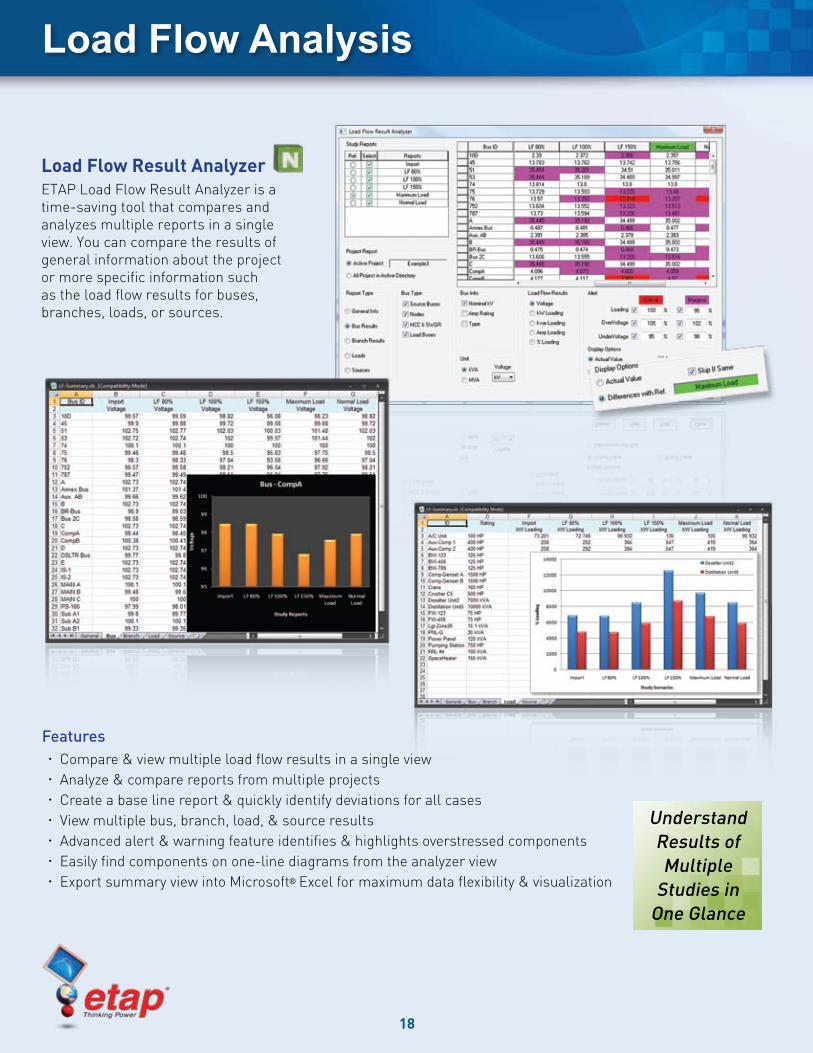
Load Flow Result AnalyzerETAP Load Flow Result Analyzer is a time-saving tool that compares and analyzes multiple reports in a single view. You can compare the results of general information about the project or more specific information such as the load flow results for buses, branches, loads, or sources.
FeaturesCompare & view multiple load flow results in a single view xAnalyze & compare reports from multiple projects xCreate a base line report & quickly identify deviations for all cases xView multiple bus, branch, load, & source results xAdvanced alert & warning feature identifies & highlights overstressed components xEasily find components on one-line diagrams from the analyzer view xExport summary view into Microsoft x ® Excel for maximum data flexibility & visualization
Understand Results of Multiple
Studies in One Glance
19
Transient Stability Analysis
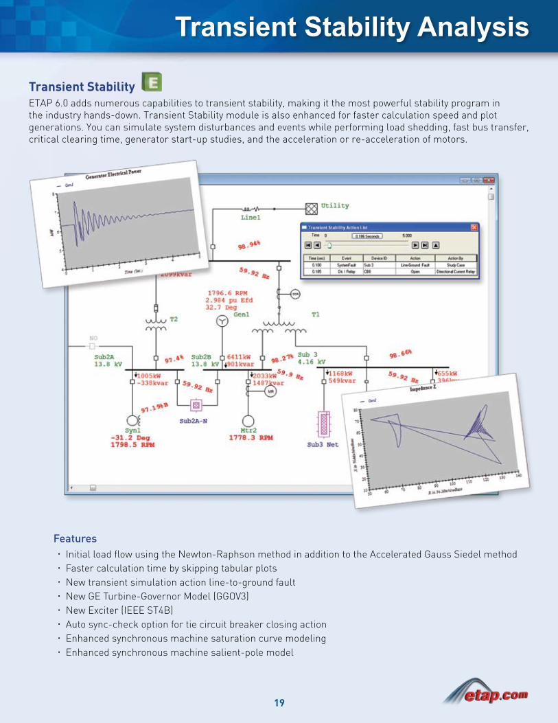
Transient StabilityETAP 6.0 adds numerous capabilities to transient stability, making it the most powerful stability program in the industry hands-down. Transient Stability module is also enhanced for faster calculation speed and plot generations. You can simulate system disturbances and events while performing load shedding, fast bus transfer, critical clearing time, generator start-up studies, and the acceleration or re-acceleration of motors.
Features Initial load flow using the Newton-Raphson method in addition to the Accelerated Gauss Siedel method xFaster calculation time by skipping tabular plots xNew transient simulation action line-to-ground fault xNew GE Turbine-Governor Model (GGOV3) xNew Exciter (IEEE ST4B) xAuto sync-check option for tie circuit breaker closing action xEnhanced synchronous machine saturation curve modeling xEnhanced synchronous machine salient-pole model x
20
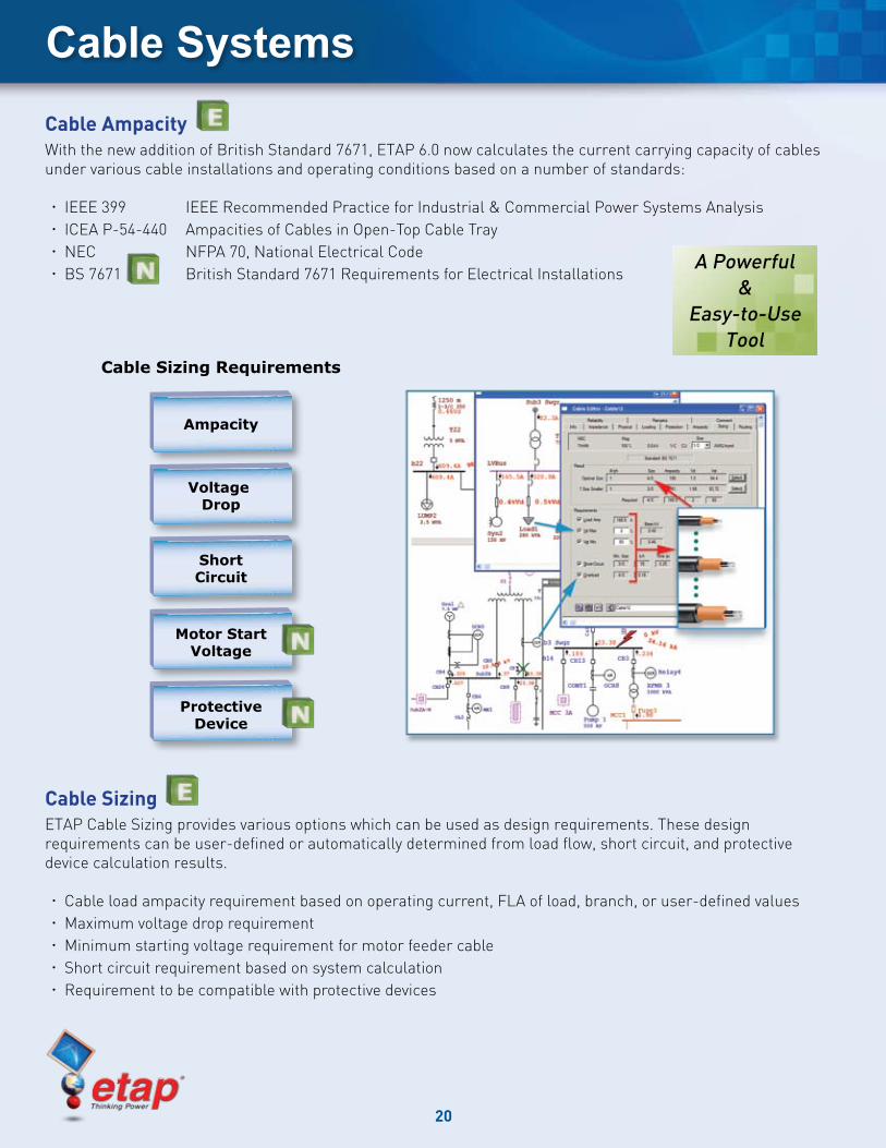
Cable SystemsCable Ampacity With the new addition of British Standard 7671, ETAP 6.0 now calculates the current carrying capacity of cables under various cable installations and operating conditions based on a number of standards:
IEEE 399 IEEE Recommended Practice for Industrial & Commercial Power Systems Analysis xICEA P-54-440 Ampacities of Cables in Open-Top Cable Tray xNEC NFPA 70, National Electrical Code xBS 7671 British Standard 7671 Requirements for Electrical Installations x
Cable SizingETAP Cable Sizing provides various options which can be used as design requirements. These design requirements can be user-defined or automatically determined from load flow, short circuit, and protective device calculation results.
Cable load ampacity requirement based on operating current, FLA of load, branch, or user-defined values xMaximum voltage drop requirement xMinimum starting voltage requirement for motor feeder cable xShort circuit requirement based on system calculation xRequirement to be compatible with protective devices x
A Powerful&
Easy-to-Use Tool
Ampacity
Voltage Drop
ShortCircuit
Motor StartVoltage
ProtectiveDevice
Cable Sizing Requirements
21
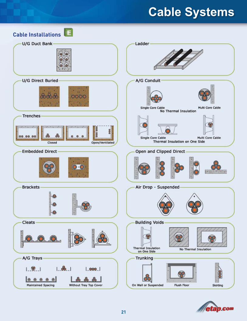
Cable SystemsCable Installations
22
Data Exchange
Data ExchangeETAP Data Exchange is used to import, export, and synchronize data between external data sources and ETAP. DataX provides many utilities including:
Legacy data transformation into ETAP xInterface with external architecture databases xCustomizable data mapping xIntelligent error checking xAutomatic one-line diagram generation x
DataX includes several new conversion programs that allow for conversion of third party electrical power system databases to ETAP. The conversion program will automatically generate a multi-layered graphical one-line diagram. A list of available conversion programs are available upon request.
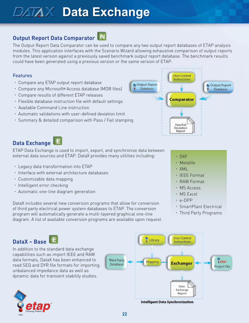
DataX – BaseIn addition to the standard data exchange capabilities such as import IEEE and RAW data formats, DataX has been enhanced to read SEQ and DYR file formats for importing unbalanced impedance data as well as dynamic data for transient stability studies.
Output Report Data ComparatorThe Output Report Data Comparator can be used to compare any two output report databases of ETAP analysis modules. This application interfaces with the Scenario Wizard allowing exhaustive comparison of output reports from the latest version against a previously saved benchmark output report database. The benchmark results could have been generated using a previous version or the same version of ETAP.
FeaturesCompare any ETAP output report database xCompare any Microsoft x ® Access database (MDB files)Compare results of different ETAP releases xFlexible database instruction file with default settings xAvailable Command Line instruction xAutomatic validations with user-defined deviation limit xSummary & detailed comparison with Pass / Fail stamping x
DXF xMetafile xXML xIEEE Format xRAW Format xMS Access xMS Excel xe-DPP xSmartPlant Electrical xThird Party Programs x
23
ETAP Support
Keep Up-to-Date with ETAP Product UpdatesImproving and expanding our products is a continual process for the ETAP development team. These ongoing product updates ensure that ETAP continues to not only meet, but exceed our customer requirements.
ETAP Upgrade & User-Support Contract (UUC)One of the best ways to get the most out of your software investment is to maintain a current maintenance contract. This ensures that your power system design, simulation, and analysis is always based on the newest, most advanced technology available. ETAP UUC includes:
All upgrades & new releases xUnlimited software support xUnlimited engineering support xAccess to the ETAP User FTP download site xReceive prerelease & beta versions of new product upgrades xFull access to OTI’s engineering expertise by your entire engineering xstaff
FeedbackOperation Technology, Inc. is dedicated to providing our customers with a superior product experience, and user feedback is one of the central elements of this commitment. In fact, ETAP is designed based on 95% of user suggestions and requests! Tell us how we are doing by:
Filling out a short survey at etap.com (click on User Feedback Form) xE-mailing ETAP Technical Support at support x @etap.comSharing your comments with your local ETAP Authorized xRepresentative
ETAP License OptionsTo meet the different needs of our varied customers, ETAP can be purchased via three licensing options, each of which has been tailored to meet specific customer needs. The newest license option is ETAP Advantage, which meets the requirements for quality assurance documentation and performance reporting. Visit etap.com for more details on the license options available.
Visit ETAP.comThe ETAP web site is your best resource for up-to-the minute information about ETAP products and services. The site includes the latest product update announcements, a worldwide training calendar, video tutorials, frequently asked questions, archived webinars, ETAP downloads, white papers and articles, information about ETAP User Groups, and much more. Click on the “Request ETAP News” link to receive periodic e-mails informing you of what’s new in ETAP.
ETAP 6.0 System Requirements
Operating System
Microsoft® Windows Vista™
Microsoft® Windows® XP (SP2) Professional or Home Edition
Microsoft® Server 2003 (SP2), Microsoft® Server 2003 R2 (SP2)
Other Software Requirements
Microsoft® Internet Explorer® 5.01 or higher (or minimum version level as specified by the operating system in use)
Microsoft® .NET Framework v1.1 (SP1)
Microsoft® .NET Framework v2.0 (SP1)
PC Configuration Requirements
Parallel port, USB port, or serial port (for stand-alone licensing only)
CD-ROM or DVD drive
5 to 80 GB hard disk space (based on project size, number of buses)
19” monitors recommended (dual monitors highly recommended)
Minimum display resolution – 1024x768
Recommended Hardware Requirements
500 Bus Projects:
Intel® Pentium® 4 – 2.0 GHz (or dual/quad core – E6600) or better
1 GB RAM
2000 Bus Projects: (Highly Recommended)
Intel® Pentium® 4 – 3.2 GHz with Hyper-Threading Technology (or dual/quad core - E6700) or better with high speed bus or equivalent
2 GB of RAM (high speed)
10000 Bus Projects and Higher:
Intel® Xeon® – 3.2 GHz with Hyper-Threading (or dual/quad core – X6800) or better with high speed system bus or AMD equivalent
2 to 4 GB RAM (high speed)

17 Goodyear, Suite 100 • Irvine, CA 92618
(800) 477-ETAP • (949) 462-0100 • Fax (949) 462-0200
OperatiOn technOlOgy, inc.


