16
THERMAL PERFORMANCE 156 TO 1348 NOMINAL TONS NEW NEW † Mark Owned by the Cooling Technology Institute. † Mr. GoodTower ® ®
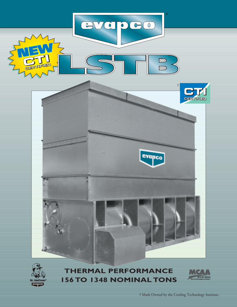
THERMAL PERFORMANCE156 TO 1348 NOMINAL TONS
NEWNEW
† Mark Owned by the Cooling Technology Institute.
†
Mr. GoodTower®
®
15723_LSTB Catalog 305 1/31/05 3:36 PM Page 1
©2005 EVAPCO, Inc.2
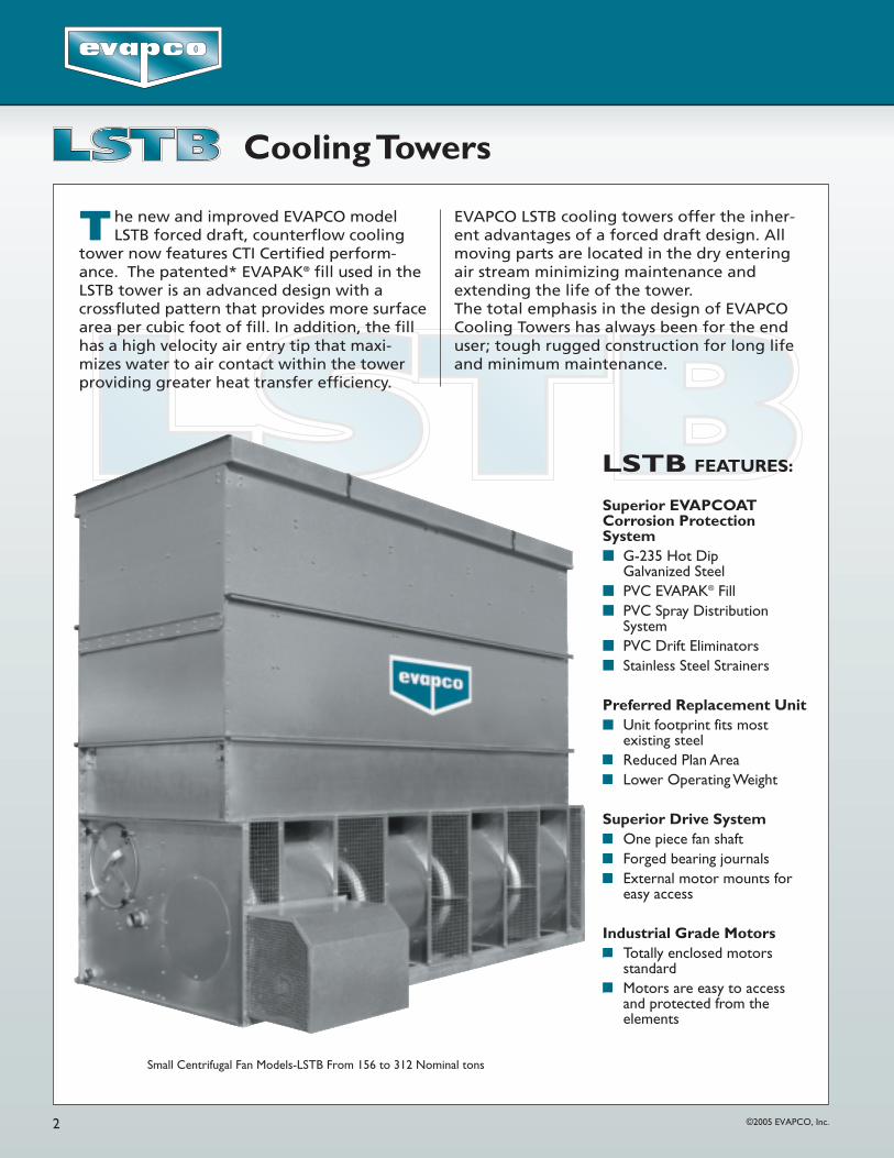
The new and improved EVAPCO modelLSTB forced draft, counterflow cooling
tower now features CTI Certified perform-ance. The patented* EVAPAK® fill used in theLSTB tower is an advanced design with acrossfluted pattern that provides more surfacearea per cubic foot of fill. In addition, the fillhas a high velocity air entry tip that maxi-mizes water to air contact within the towerproviding greater heat transfer efficiency.
EVAPCO LSTB cooling towers offer the inher-ent advantages of a forced draft design. Allmoving parts are located in the dry enteringair stream minimizing maintenance andextending the life of the tower. The total emphasis in the design of EVAPCOCooling Towers has always been for the enduser; tough rugged construction for long lifeand minimum maintenance.
Superior EVAPCOATCorrosion ProtectionSystem■ G-235 Hot Dip
Galvanized Steel■ PVC EVAPAK® Fill■ PVC Spray Distribution
System■ PVC Drift Eliminators■ Stainless Steel Strainers
Preferred Replacement Unit■ Unit footprint fits most
existing steel■ ■ Reduced Plan Area■ ■ Lower Operating Weight
Superior Drive System■ ■ One piece fan shaft■ ■ Forged bearing journals■ ■ External motor mounts for
easy access
Industrial Grade Motors■ ■ Totally enclosed motors
standard■ ■ Motors are easy to access
and protected from the elements
LSTB FEATURES:
Small Centrifugal Fan Models-LSTB From 156 to 312 Nominal tons
Cooling Towers
15723_LSTB Catalog 305 1/31/05 3:36 PM Page 2

Design Features
Application VersatilityCentrifugal fan units are recommended for a wide rangeof installations.They are excellent for larger installationswhere very quiet operation is a must, such as residentialneighborhoods. In addition, centrifugal fan units canoperate against the static pressure loss of ductwork andare ideal for indoor installations.
Very Quiet OperationCentrifugal fan units provide an inherently low noisecharacteristic which makes this design preferred formost installations that require low sound levels.Thesound they produce is predominantly in the high fre-quencies which is easily attenuated by building walls,windows, and natural barriers.Additionally, since thesound from the fans is directional, single sided air entrymodels can be turned away from critical areas avoidinga sound problem.When even quieter operation is nec-essary, centrifugal fan models can be equipped withoptional sound attenuation packages. Consult the facto-ry for details.
Indoor InstallationCentrifugal cooling towers canbe installed indoors when it isdesirable to hide the unit orwhen it is the only space avail-able. In addition to being quiet,they can handle the externalstatic pressure of ductwork byusing the next larger size fan motor. Drawings are avail-able showing how to make ductwork connections.
Blow-Thru ConstructionAll moving parts of Forced DraftTowers-fans, motors, bearing, drives,and belts, are in the the dry enteringair stream.This design feature reducescorrosion and maintenance problemsin these vital areas.
Low Installed CostsThe LSTB forced draft cooling tower is designed using amodular concept to minimize rigging, piping and sup-port costs.All major components are factory assembled
into completesections. Fans,shafts, bearingsand drives areinstalled andaligned at the fac-tory as an integralpart of the pansection to elimi-nate the necessityof field riggingthese key parts.
3
Large Centrifugal Fan Models LSTB from 228 to 1348 nominal tons
15723_LSTB Catalog 305 1/31/05 3:37 PM Page 3

4
Fan Motors
All LSTB models utilize heavy duty totally enclosed fanmotors (T.E.F.C.) designed specifically for coolingtower applications. In addition, EVAPCO offers manyoptional motors to meet your specific needs, including:
■ Premium Efficiency Motors■ Multi-Speed Motors■ Inverter-Duty Motors for VFD Applications
Fan Motor Location
EVAPCO mounts the fan motor in a convenient openarea to make it easy to adjust belt tension, access themotor, electrically connect it, or change the motor ifnecessary. The fan motor and drive are under a protec-tive cover for safety purposes and to protect themfrom the elements.
Centrifugal Fan Assembly
Fans on the LSTB models are of the forward curvedcentrifugal type with hot-dip galvanized steel construc-tion. All fans are statically and dynamically balanced andmounted in a hot-dip galvanized steel housing designedand manufactured by EVAPCO.
Design Features
LARGE SERIES MOTOR MOUNT
SMALL SERIES MOTOR MOUNT
Forged Bearing Journal
The fan shafts used on all LSTB models are standardwith forged bearing journals, eliminating the two-piecefan shaft with welded end journals, which is susceptibleto rusting and eventual failure. The solid forged designof the LSTB fan shaft provides durable long-lastingoperation, free from pre-mature mechanical failure.
CENTRIFUGAL WHEEL
15723_LSTB Catalog 305 1/31/05 3:37 PM Page 4
5
Design Features
Two Speed Motors
For those installations requiring close control, twospeed 1800/900 RPM motors are an excellent methodof capacity control. This arrangement gives capacitysteps of 10% (fans off), 60% (fans halfspeed) and 100%. Atemperature controller can be supplied to set controlsteps at 5°, so fairly close temperature control can bemaintained without excessive cycling of the fan motor.
Two-speed motors also save operating costs. At half-speed, the motor draws less than 15% of full loadpower. Since maximum wet bulb and maximum loadvery seldom coincide, the cooling tower will actuallyoperate at half-speed as much as 80% of the time. Thus,power costs will be reduced by approximately 85% dur-ing the major portion of the operating season.
A third advantage of two-speed motors is that noiselevels are reduced by 6 to 8 dB when operating at half-speed. Since both the load and the wet bulb are nor-mally lower at night, the tower will operate at lowspeed and the noise level will be substantially reducedduring this noise sensitive period.Caution – The water circulation pump must beinterlocked with the fan motor starter(s) to insurewater flow over the tower fill during fan operation.
Inverter Duty Motors
EVAPCO recommends the use of Inverter Duty Motorswhen Variable Frequency Drives are utilized for capacitycontrol. Inverter Duty Motors are available as an option.
Accessibility
The pan/fan section of a centrifugal fan unit is designed foraccessibility and maintenance. Fan and drive componentsare positioned to allow easy adjustment and cleaning. Allgrease fittings are in convenient locations for periodiclubrication. Large circular access doors are provided oneach section to allow entry into the pan. All float valveand strainer assemblies are located near the door foreasy adjustment and cleaning. The pan sump is designedto catch the dirt accumulated and can be flushed out witha hose.
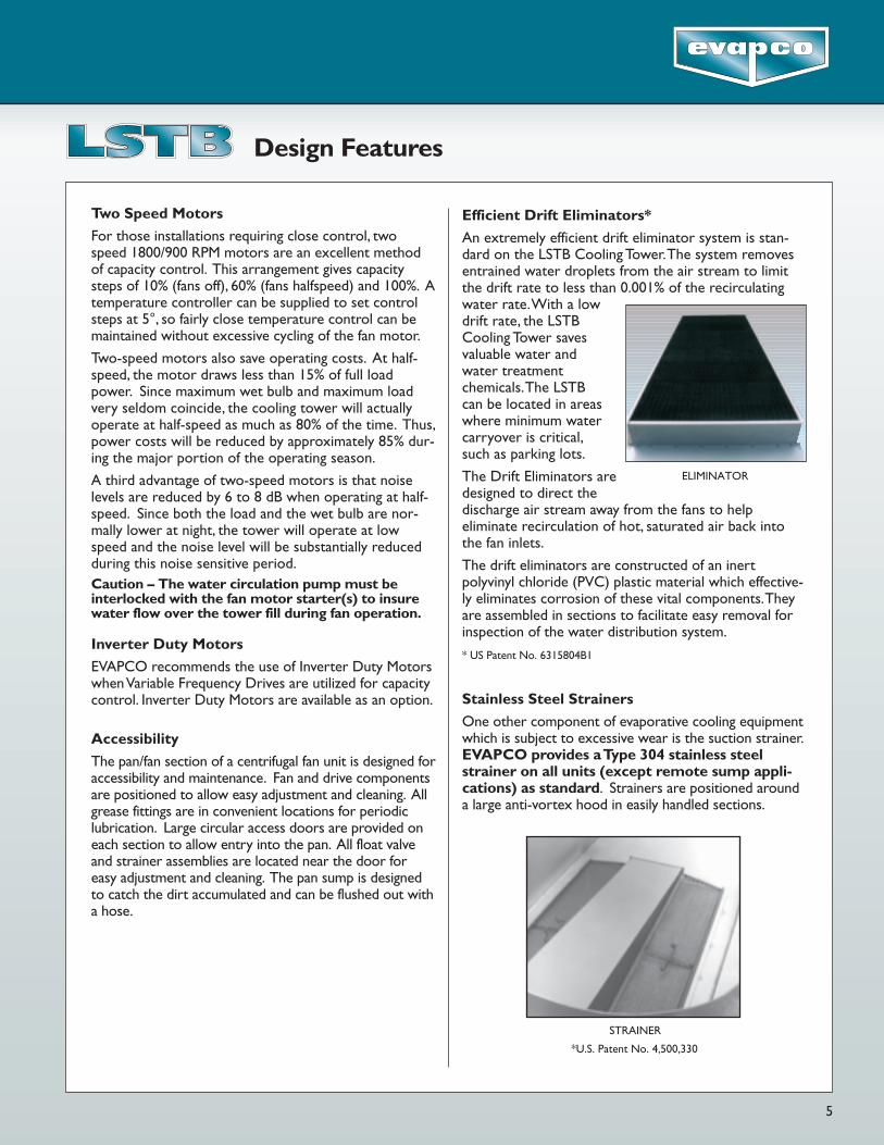
Efficient Drift Eliminators*
An extremely efficient drift eliminator system is stan-dard on the LSTB Cooling Tower.The system removesentrained water droplets from the air stream to limitthe drift rate to less than 0.001% of the recirculatingwater rate.With a lowdrift rate, the LSTBCooling Tower saves valuable water andwater treatment chemicals.The LSTB can be located in areaswhere minimum watercarryover is critical,such as parking lots.
The Drift Eliminators aredesigned to direct the discharge air stream away from the fans to help eliminate recirculation of hot, saturated air back intothe fan inlets.
The drift eliminators are constructed of an inertpolyvinyl chloride (PVC) plastic material which effective-ly eliminates corrosion of these vital components.Theyare assembled in sections to facilitate easy removal forinspection of the water distribution system.
* US Patent No. 6315804B1
Stainless Steel Strainers
One other component of evaporative cooling equipmentwhich is subject to excessive wear is the suction strainer.EVAPCO provides a Type 304 stainless steelstrainer on all units (except remote sump appli-cations) as standard. Strainers are positioned arounda large anti-vortex hood in easily handled sections.
ELIMINATOR
STRAINER
*U.S. Patent No. 4,500,330
15723_LSTB Catalog 305 2/4/05 10:16 AM Page 5
6
EVAPCOAT:
G-235 Hot-Dip Galvanized Steel
Construction
The standard material of construction for evaporativecooling equipment for many years has been hot-dip gal-vanized steel. The purpose of galvanizing is to protectthe base metal from corrosion, and the thickness of thegalvanized layer directly affects the equipment life.
EVAPCO has been instrumental in the development ofcorrosion protection technology and was the first manu-facturer to use G-235 galvanized steel construction. TheG-235 designation equates to a minimum of 2.35 ouncesof zinc per square foot of surface area.
The EVAPCOAT Corrosion Protection System isthe heaviest galvanized coating available forextended corrosion protection eliminating theneed for costly, unreliable epoxy paint finishes.
Stainless Steel Material Options
The EVAPCOAT Corrosion Protection System is satis-factory for most applications. If additional corrosion pro-tection is required the following stainless steel optionsare available. Please contact your local EVAPCO repre-sentative for pricing.
■ Stainless Steel Cold Water Basins:Models LSTB 8112 to 8536Models LSTB 10112 to 10636
■ ■ Stainless Steel Water Touch Basin:All LSTB Models
■ ■ Stainless Steel Water Touch Units:All LSTB Models
■ ■ All Stainless Steel Units:All LSTB Models
Consult the factory for construction details.
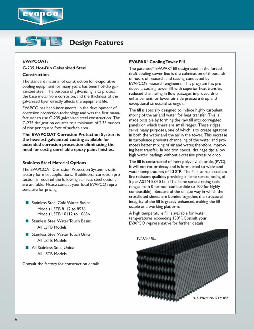
EVAPAK® Cooling Tower Fill
The patented* EVAPAK® fill design used in the forceddraft cooling tower line is the culmination of thousandsof hours of research and testing conducted byEVAPCO’s research engineers. This program has pro-duced a cooling tower fill with superior heat transfer,reduced channeling in flow passages, improved dripenhancement for lower air side pressure drop andexceptional structural strength.
The fill is specially designed to induce highly turbulentmixing of the air and water for heat transfer. This ismade possible by forming the raw fill into corrugatedpanels on which there are small ridges. These ridgesserve many purposes, one of which is to create agitationin both the water and the air in the tower. This increasein turbulence prevents channeling of the water and pro-motes better mixing of air and water, therefore improv-ing heat transfer. In addition, special drainage tips allowhigh water loadings without excessive pressure drop.
The fill is constructed of inert polyvinyl chloride, (PVC).It will not rot or decay and is formulated to withstandwater temperatures of 130°F. The fill also has excellentfire resistant qualities providing a flame spread rating of5 per ASTM-E84-81a. (The flame spread rating scaleranges from 0 for non-combustible to 100 for highlycombustible). Because of the unique way in which thecrossfluted sheets are bonded together, the structuralintegrity of the fill is greatly enhanced, making the fillusable as a working platform.
A high temperature fill is available for water temperatures exceeding 130°F. Consult your EVAPCO representative for further details.
Design Features
EVAPAK® FILL
*U.S. Patent No. 5,124,087
15723_LSTB Catalog 305 1/31/05 3:38 PM Page 6
7
Optional Equipment
Pan Freeze ProtectionRemote SumpWhenever a cooling tower is idle during sub-freezingweather, the water in the sump must be protected fromfreezing and damaging the pan. The simplest and most reli-able method of accomplishing this is with a remote sumptank located in a heated space in the building under thetower. With this system, the water in the tower drains tothe indoor tank whenever the pump is shut-off. When atower is ordered for remote sump operation, the standardfloat valve and strainer are omitted, and the unit is providedwith an oversized water out connection. When a remotesump is not possible, a supplementary means of heating thepan water must be provided.
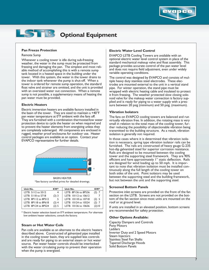
Electric HeatersElectric immersion heaters are available factory installed inthe basin of the tower. They are sized to maintain a +40°Fpan water temperature at 0°F ambient with the fans off.They are furnished with a combination thermostat/low waterprotection device to cycle the heater on when required andto prevent the heater elements from energizing unless theyare completely submerged. All components are enclosed inrugged, weather proof enclosures for outdoor use. Heatercontrol packages are available as an option. Contact yourEVAPCO representative for further details.
Steam or Hot Water CoilsPan coils are available as an alternate to the electric heatersdescribed above. Constructed of galvanized pipe installedin the cooling tower basin, they are supplied less controlsand are ready for piping to an external steam or hot watersource. Pan water heater controls should be interlockedwith the water circulating pump to prevent their operationwhen the pump is energized.
Electric Water Level ControlEVAPCO LSTB Cooling Towers are available with anoptional electric water level control system in place of thestandard mechanical makeup valve and float assembly. Thispackage provides accurate control of the pan water leveland does not require field adjustment, even under widelyvariable operating conditions.The control was designed by EVAPCO and consists of mul-tiple heavy duty stainless steel electrodes. These elec-trodes are mounted external to the unit in a vertical standpipe. For winter operation, the stand pipe must bewrapped with electric heating cable and insulated to protectit from freezing. The weather protected slow closing sole-noid valve for the makeup water connection is factory sup-plied and is ready for piping to a water supply with a pres-sure between 20 psig (minimum) and 50 psig. (maximum).
Vibration IsolatorsThe fans on EVAPCO cooling towers are balanced and runvirtually vibration free. In addition, the rotating mass is verysmall in relation to the total mass of the cooling tower, fur-ther reducing the possibility of objectionable vibration beingtransmitted to the building structure. As a result, vibrationisolation is generally not required. In those cases where it is determined that vibration isola-tion is necessary, spring type vibration isolator rails can befurnished. The rails are constructed of heavy gauge G-235hot-dip galvanized steel for superior corrosion resistance.Rails are designed to be mounted between the coolingtower and the supporting steel framework. They are 90%efficient and have approximately 1” static deflection. Railsare designed for wind loading up to 50 mph. It is impor-tant to note that vibration isolation must be installed con-tinuously along the full length of the cooling tower onboth sides of the unit. Point isolators may be usedbetween the supporting steel and the building framework,but not between the unit and the supporting steel.
Screened Bottom PanelsProtective inlet screens are provided on the front of the fansection on the LSTB. Screens are not provided on the bot-tom of the fan section since most units are mounted on theroof or at ground level.If units are installed in an elevated position, bottom screensare recommended for safety protection.
Other Options Available:Capacity Dampers and ControlsPony MotorsLaddersInverter Duty and 2 Speed MotorsSteam InjectorsStainless Steel Fan ShaftsTapered Discharge HoodsSolid Bottom Panels
BASIN HEATER*See factory certified prints for detailed drawings.
*
Unit No. KW* Unit No. KW*LSTB 5112 to 5512 4 LSTB 8P136 to 8P536 (2) 7LSTB 5118 to 5718 (2) 3 LSTB 10112 to 10612 7LSTB 8P112 to 8P512 5 LSTB 10118 to 10718 (2) 5LSTB 8P118 to 8P618 (2) 4 LSTB 10124 to 10524 (2) 7LSTB 8P124 to 8P524 (2) 5 LSTB 10136 to 10636 (2)10
* Electric heater selection based on 0°F ambient temperature. For alternatelow ambient heater selections, consult the factory.
15723_LSTB Catalog 305 1/31/05 3:38 PM Page 7
8
Applications
DesignEVAPCO LSTB Cooling Towers have heavy-duty construc-tion and are designed for long, trouble-free operation.However, proper equipment selection, installation andmaintenance are necessary to insure good unit perform-ance. Some of the major considerations in the applicationof a cooling tower are presented below. For additionalinformation, contact the factory.
Air CirculationIn reviewing the system design and unit location, it is impor-tant that enough fresh air is provided to enable proper unitperformance. The best location is on an unobstructed rooftop or on ground level away from walls and other barriers.Care must be taken when locating towers in wells or enclo-sures or next to high walls. The potential for recirculationof the hot, moist discharge air back into the fan intakeexists. Recirculation raises the wet bulb temperature of theentering air causing the leaving water temperature to riseabove design. For these cases, a discharge hood or duct-work should be provided to raise the overall unit heighteven with the adjacent wall, thereby reducing the chance ofrecirculation. For additional information see the EVAPCOEquipment Layout Manual. Engineering assistance is alsoavailable from the factory to identify potential recirculationproblems and recommend solutions.
Sound AttenuationThe centrifugal fan design of theLSTB models operate at lower soundlevels which make the units prefer-able for installations where noise is aconcern. For extremely noise sensi-tive installations, the LSTB modelsmay be supplied with inlet and/or discharge attenuationpackages which greatly reduce the sound levels. Evapcooffers Inlet and/or discharge attenuation packageswith CTI Certified performance.Discharge attenuation quiets sound radiating from thetop of the unit and features a tapered design with insulatedwalls acoustically lined with high density fiberglass. Inlet attenuation reduces sound radiated through thetower air intakes and consists of acoustically lined baffles tochange the path of the air entry and capture radiated noise.
PipingCooling tower piping should be designed and installed inaccordance with generally accepted engineering practices.All piping should be anchored by properly designed hang-ers and supports with allowance made for possible expan-sion and contraction. No external loads should be placedupon cooling tower connections, nor should any of thepipe supports be anchored to the unit framework.
Maintaining the Recirculated Water SystemThe cooling in a tower is accomplished by the evaporationof a portion of the recirculated spray water. As this waterevaporates, it leaves behind all of its mineral content andimpurities. Therefore, it is important to bleed-off anamount of water equal to that which is evaporated to pre-vent the buildup of impurities. If this is not done, the miner-al content and/or the corrosive nature of the water willcontinue to increase. This will ultimately result in heavyscaling or a corrosive condition.
Bleed-offA bleed line should be installed in the piping, external tothe unit. The bleed line must be properly sized for theapplication and provided with a metering connection andglobe valve. The recommended bleed off for a coolingtower is equivalent to the evaporation rate of 3 gpm per100 tons of cooling. If the make-up water supplying theunit is relatively free of impurities, it may be possible to cutback the bleed, but the unit must be checked frequently tomake sure scale is not forming. Make-up water pressuremust be maintained between 20 and 50 psig for properoperation of the float valve.
Water TreatmentIn some cases the make-up water will be so high in mineralcontent that a normal bleed-off will not prevent scaling. Inthis case water treatment will be required and a reputablewater treatment company familiar with the local water con-ditions should be consulted. Any chemical water treatment used must be compatiblewith the stainless or galvanized construction of the unit.The pH of the water should be maintained between 6.5 and8.0. In order to prevent “white rust”, the galvanized steel inthe unit may require routine passivation of the steel whenoperating in higher pH levels. Batch chemical feeding is notrecommended because it does not afford the proper degreeof control. If acid cleaning is required extreme caution mustbe exercised and only inhibited acids compatible with galva-nized steel construction should be used.
Control of Biological ContaminationWater quality should be checked regularly for biological con-tamination. If biological contamination is detected, a moreaggressive water treatment and mechanical cleaning programshould be undertaken. The water treatment program shouldbe performed by a qualified water treatment company. It isimportant that all internal surfaces be kept clean of accumu-lated dirt and sludge. In addition, the drift eliminators shouldbe maintained in good operating condition.
Note: The location of the cooling tower must beconsidered during the equipment layout stages of aproject. It is important to prevent the discharge air(potential of biological contamination) from beingintroduced into the fresh air intakes of the building.
† Mark Owned by the Cooling Technology Institute.
†
15723_LSTB Catalog 305 1/31/05 3:39 PM Page 8

9
Specifications
Furnish and install as shown on the plans an EVAPCOModel __________ blow-through cooling tower. Eachunit shall have the capacity to cool __________ GPMof water from __________ °F to __________ °F witha __________ °F entering wet bulb temperature. Thetower shall operate against __________ w.g. externalstatic pressure. Unit height shall not exceed _________.Additionally, the thermal performance shall be certifiedby the Cooling Technology Institute in accordance withCTI Standard 201.Non-CTI Certified units will not be acceptable.
Basin and CasingThe basin and casing shall be constructed of G-235 hot-dip galvanized steel for long life and durability. The heattransfer section shall be removable from the pan toprovide easy handling and rigging.The basin/fan section shall include fans and drivesmounted and aligned at the factory. These items shallbe located in the dry entering air stream to providemaximum service life and easy maintenance. Standardpan accessories shall include circular access doors,stainless steel strainers, and brass make-up valve withunsinkable, foam filled plastic float.
Centrifugal Fans/DrivesFans shall be forwardly curved centrifugal type of hotdip galvanized construction. The fans shall be factoryinstalled into the fan/pan section, and statically anddynamically balanced for vibration free operation. Fansshall be mounted on either a solid steel shaft or a hol-low steel shaft with forged bearing journals. The fanshaft shall be supported by heavy-duty, self-aligningbearings with cast iron housings and lubrication fittingsfor maintenance.The fan drives shall be V-belt type with taper locksheaves designed for 150% of the motor nameplatehorsepower.
Fan Motor__________ horsepower T.E.F.C. ball bearing fanmotor(s) with 1.15 service factor shall be furnishedsuitable for outdoor service on __________ volts,__________ hertz, and __________ phase. Motor(s)shall be mounted on an adjustable base.
Fill Section*The cooling tower fill shall be PVC (Polyvinyl Chloride)of cross-fluted design for optimum heat transfer and effi-ciency. The cross-fluted sheets shall be bonded togetherfor strength and durability. The PVC fill shall be self-extinguishing for fire resistance with a flame spread rat-ing of 5 per ASTM E84-81a. It shall also be resistant torot, decay or biological attack.
Water Distribution SystemThe spray header and branches shall be constructed ofSchedule 40, polyvinyl chloride (PVC) pipe for corrosionresistance and shall have a steel connection to attach theexternal piping. The water shall be distributed over thefill by precision molded ABS spray nozzles with large 3⁄8by 1 inch orifice openings and integral sludge ring toeliminate clogging. The internal tower water distributionpiping shall be removable for cleaning purposes.
EliminatorsThe eliminators shall be constructed of inert polyvinylchloride (PVC) that has been specially treated to resistultra violet light. Assembled in easily handled sections,the eliminator shall incorporate three changes in airdirection to assure removal of entrained moisture fromthe discharge air stream.The drift rate shall not exceed 0.001% of the recirculatedflow rate.
FinishAll pan and casing materials shall be constructed of G-235 heavy gauge mill hot-dip galvanized steel for maxi-mized protection against corrosion. During fabrication,all panel edges shall be coated with a 95% pure zinc-compound.Coated finishes shall not be acceptable.
* The LSTB uses the patented EVAPAK® fill (US Patent No.5,124,087) which is designed to induce highly turbulentmixing of the air and water for superior heat transfer.
15723_LSTB Catalog 305 2/4/05 10:16 AM Page 9
10
Thermal Performance
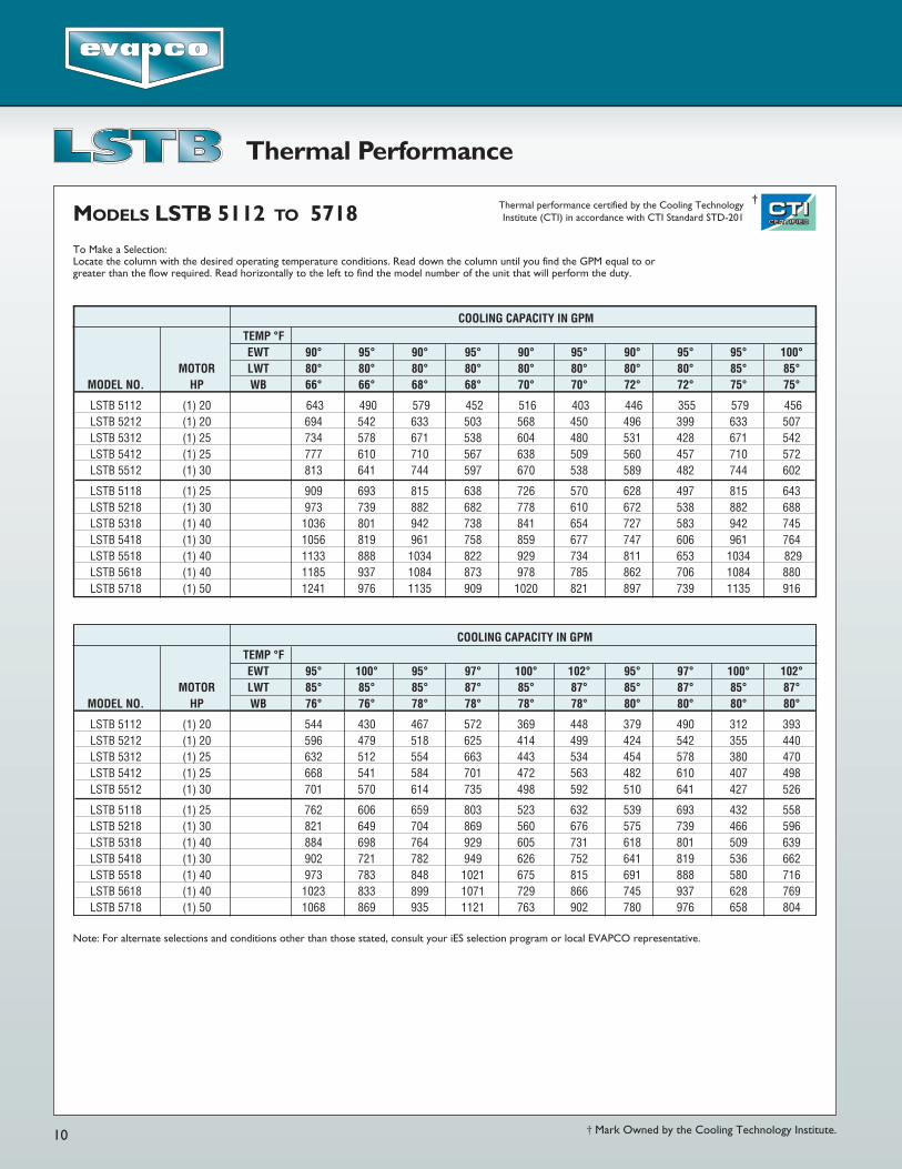
MODELS LSTB 5112 TO 5718†Thermal performance certified by the Cooling Technology
Institute (CTI) in accordance with CTI Standard STD-201
† Mark Owned by the Cooling Technology Institute.
COOLING CAPACITY IN GPMTEMP °FEWT 90° 95° 90° 95° 90° 95° 90° 95° 95° 100°
MOTOR LWT 80° 80° 80° 80° 80° 80° 80° 80° 85° 85°MODEL NO. HP WB 66° 66° 68° 68° 70° 70° 72° 72° 75° 75°
LSTB 5112 (1) 20 643 490 579 452 516 403 446 355 579 456LSTB 5212 (1) 20 694 542 633 503 568 450 496 399 633 507LSTB 5312 (1) 25 734 578 671 538 604 480 531 428 671 542LSTB 5412 (1) 25 777 610 710 567 638 509 560 457 710 572LSTB 5512 (1) 30 813 641 744 597 670 538 589 482 744 602
LSTB 5118 (1) 25 909 693 815 638 726 570 628 497 815 643LSTB 5218 (1) 30 973 739 882 682 778 610 672 538 882 688LSTB 5318 (1) 40 1036 801 942 738 841 654 727 583 942 745LSTB 5418 (1) 30 1056 819 961 758 859 677 747 606 961 764LSTB 5518 (1) 40 1133 888 1034 822 929 734 811 653 1034 829LSTB 5618 (1) 40 1185 937 1084 873 978 785 862 706 1084 880LSTB 5718 (1) 50 1241 976 1135 909 1020 821 897 739 1135 916
COOLING CAPACITY IN GPMTEMP °FEWT 95° 100° 95° 97° 100° 102° 95° 97° 100° 102°
MOTOR LWT 85° 85° 85° 87° 85° 87° 85° 87° 85° 87°MODEL NO. HP WB 76° 76° 78° 78° 78° 78° 80° 80° 80° 80°
LSTB 5112 (1) 20 544 430 467 572 369 448 379 490 312 393LSTB 5212 (1) 20 596 479 518 625 414 499 424 542 355 440LSTB 5312 (1) 25 632 512 554 663 443 534 454 578 380 470LSTB 5412 (1) 25 668 541 584 701 472 563 482 610 407 498LSTB 5512 (1) 30 701 570 614 735 498 592 510 641 427 526
LSTB 5118 (1) 25 762 606 659 803 523 632 539 693 432 558LSTB 5218 (1) 30 821 649 704 869 560 676 575 739 466 596LSTB 5318 (1) 40 884 698 764 929 605 731 618 801 509 639LSTB 5418 (1) 30 902 721 782 949 626 752 641 819 536 662LSTB 5518 (1) 40 973 783 848 1021 675 815 691 888 580 716LSTB 5618 (1) 40 1023 833 899 1071 729 866 745 937 628 769LSTB 5718 (1) 50 1068 869 935 1121 763 902 780 976 658 804
To Make a Selection:Locate the column with the desired operating temperature conditions. Read down the column until you find the GPM equal to orgreater than the flow required. Read horizontally to the left to find the model number of the unit that will perform the duty.
Note: For alternate selections and conditions other than those stated, consult your iES selection program or local EVAPCO representative.
†
15723_LSTB Catalog 305 1/31/05 4:03 PM Page 10
11
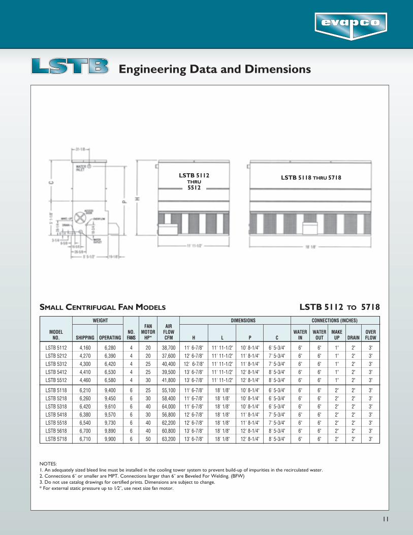
SMALL CENTRIFUGAL FAN MODELS LSTB 5112 TO 5718
NOTES:1. An adequately sized bleed line must be installed in the cooling tower system to prevent build-up of impurities in the recirculated water.2. Connections 6˝ or smaller are MPT. Connections larger than 6˝ are Beveled For Welding. (BFW)3. Do not use catalog drawings for certified prints. Dimensions are subject to change.* For external static pressure up to 1⁄2˝, use next size fan motor.
WEIGHT DIMENSIONS CONNECTIONS (INCHES)FAN AIR
MODEL NO. MOTOR FLOW WATER WATER MAKE OVERNO. SHIPPING OPERATING FANS HP* CFM H L P C IN OUT UP DRAIN FLOW
LSTB 5112 4,160 6,280 4 20 38,700 11' 6-7/8" 11' 11-1/2" 10' 8-1/4" 6' 5-3/4" 6" 6" 1" 2" 3"LSTB 5212 4,270 6,390 4 20 37,600 12' 6-7/8" 11' 11-1/2" 11' 8-1/4" 7' 5-3/4" 6" 6" 1" 2" 3"LSTB 5312 4,300 6,420 4 25 40,400 12' 6-7/8" 11' 11-1/2" 11' 8-1/4" 7' 5-3/4" 6" 6" 1" 2" 3"LSTB 5412 4,410 6,530 4 25 39,500 13' 6-7/8" 11' 11-1/2" 12' 8-1/4" 8' 5-3/4" 6" 6" 1" 2" 3"LSTB 5512 4,460 6,580 4 30 41,800 13' 6-7/8" 11' 11-1/2" 12' 8-1/4" 8' 5-3/4" 6" 6" 1" 2" 3"
LSTB 5118 6,210 9,400 6 25 55,100 11' 6-7/8" 18' 1/8" 10' 8-1/4" 6' 5-3/4" 6" 6" 2" 2" 3"LSTB 5218 6,260 9,450 6 30 58,400 11' 6-7/8" 18' 1/8" 10' 8-1/4" 6' 5-3/4" 6" 6" 2" 2" 3"LSTB 5318 6,420 9,610 6 40 64,000 11' 6-7/8" 18' 1/8" 10' 8-1/4" 6' 5-3/4" 6" 6" 2" 2" 3"LSTB 5418 6,380 9,570 6 30 56,800 12' 6-7/8" 18' 1/8" 11' 8-1/4" 7' 5-3/4" 6" 6" 2" 2" 3"LSTB 5518 6,540 9,730 6 40 62,200 12' 6-7/8" 18' 1/8" 11' 8-1/4" 7' 5-3/4" 6" 6" 2" 2" 3"LSTB 5618 6,700 9,890 6 40 60,800 13' 6-7/8" 18' 1/8" 12' 8-1/4" 8' 5-3/4" 6" 6" 2" 2" 3"LSTB 5718 6,710 9,900 6 50 63,200 13' 6-7/8" 18' 1/8" 12' 8-1/4" 8' 5-3/4" 6" 6" 2" 2" 3"
Engineering Data and Dimensions
LSTB 5112 THRU 5512
LSTB 5118 THRU 5718
15723_LSTB Catalog 305 1/31/05 3:40 PM Page 11

12
Thermal Performance
MODELS LSTB 8P112 TO 8P536 Thermal performance certified by the Cooling TechnologyInstitute (CTI) in accordance with CTI Standard STD-201
† Mark Owned by the Cooling Technology Institute.
COOLING CAPACITY IN GPMTEMP °FEWT 90° 95° 90° 95° 90° 95° 90° 95° 95° 100°
MOTOR LWT 80° 80° 80° 80° 80° 80° 80° 80° 85° 85°MODEL NO. HP WB 66° 66° 68° 68° 70° 70° 72° 72° 75° 75°LSTB 8P112 (1) 30 945 725 867 663 762 588 657 518 876 677LSTB 8P212 (1) 40 1041 805 958 737 845 656 730 577 968 753LSTB 8P312 (1) 40 1132 891 1047 822 932 738 815 657 1056 838LSTB 8P412 (1) 40 1179 936 1093 868 977 786 861 706 1102 884LSTB 8P512 (1) 50 1261 1004 1170 931 1048 843 924 758 1180 948LSTB 8P118 (1) 40 1368 1047 1254 957 1101 848 948 746 1266 977LSTB 8P218 (1) 50 1477 1136 1357 1040 1194 923 1030 812 1370 1063LSTB 8P318 (1) 40 1500 1173 1384 1080 1228 968 1071 860 1397 1102LSTB 8P418 (1) 50 1611 1264 1489 1165 1323 1046 1155 931 1502 1188LSTB 8P518 (1) 60 1707 1343 1579 1239 1405 1113 1229 991 1593 1263LSTB 8P618 (1) 60 1778 1412 1648 1310 1474 1185 1299 1064 1662 1333LSTB 8P124 (2) 25 1949 1522 1798 1402 1595 1256 1390 1116 1814 1430LSTB 8P224 (2) 40 2081 1609 1917 1474 1690 1311 1461 1155 1935 1505LSTB 8P324 (2) 40 2264 1781 2094 1643 1863 1476 1629 1315 2112 1675LSTB 8P424 (2) 40 2357 1873 2186 1737 1955 1572 1723 1412 2204 1768LSTB 8P524 (2) 50 2522 2008 2340 1862 2095 1686 1847 1516 2360 1896LSTB 8P136 (3) 30 2835 2175 2602 1989 2286 1765 1970 1553 2628 2032LSTB 8P236 (3) 40 3122 2414 2875 2211 2535 1967 2191 1732 2903 2258LSTB 8P336 (3) 40 3396 2672 3140 2465 2795 2214 2444 1972 3169 2513LSTB 8P436 (3) 40 3536 2809 3278 2605 2932 2358 2584 2117 3307 2652LSTB 8P536 (3) 50 3784 3011 3510 2793 3143 2529 2771 2273 3540 2844
COOLING CAPACITY IN GPMTEMP °FEWT 95° 100° 95° 97° 100° 102° 95° 97° 100° 102°
MOTOR LWT 85° 85° 85° 87° 85° 87° 85° 87° 85° 87°MODEL NO. HP WB 76° 76° 78° 78° 78° 78° 80° 80° 80° 80°LSTB 8P112 (1) 30 822 637 705 872 554 679 567 741 459 585LSTB 8P212 (1) 40 910 709 782 964 618 754 632 822 513 652LSTB 8P312 (1) 40 997 793 868 1052 699 839 714 908 589 735LSTB 8P412 (1) 40 1043 839 914 1098 747 885 762 954 638 783LSTB 8P512 (1) 50 1117 900 979 1176 802 949 818 1023 685 840LSTB 8P118 (1) 40 1188 919 1016 1261 799 979 818 1071 662 844LSTB 8P218 (1) 50 1286 998 1103 1364 868 1064 890 1161 720 919LSTB 8P318 (1) 40 1317 1041 1142 1391 916 1104 936 1197 771 964LSTB 8P418 (1) 50 1417 1123 1231 1496 989 1190 1011 1290 834 1041LSTB 8P518 (1) 60 1504 1195 1308 1587 1054 1265 1077 1370 889 1108LSTB 8P618 (1) 60 1573 1266 1378 1656 1126 1335 1149 1439 962 1180LSTB 8P124 (2) 25 1710 1350 1481 1807 1187 1432 1214 1553 999 1250LSTB 8P224 (2) 40 1819 1418 1564 1927 1235 1508 1265 1644 1025 1305LSTB 8P324 (2) 40 1994 1585 1735 2104 1398 1678 1429 1817 1179 1470LSTB 8P424 (2) 40 2086 1679 1827 2196 1493 1771 1524 1908 1275 1565LSTB 8P524 (2) 50 2235 1800 1959 2352 1603 1899 1636 2045 1371 1679LSTB 8P136 (3) 30 2465 1911 2114 2617 1661 2036 1701 2223 1377 1756LSTB 8P236 (3) 40 2729 2127 2346 2891 1853 2262 1897 2466 1538 1957LSTB 8P336 (3) 40 2992 2378 2603 3157 2097 2517 2143 2725 1768 2205LSTB 8P436 (3) 40 3129 2518 2741 3295 2240 2656 2286 2863 1913 2348LSTB 8P536 (3) 50 3352 2701 2938 3527 2405 2848 2453 3068 2056 2519
To Make a Selection:Locate the column with the desired operating temperature conditions. Read down the column until you find the GPM equal toor greater than the flow required. Read horizontally to the left to find the model number of the unit that will perform the duty.
Note: For alternate selections and conditions other than those stated, consult your iES selection program or local EVAPCO representative.
†
15723_LSTB Catalog 305 1/31/05 3:40 PM Page 12
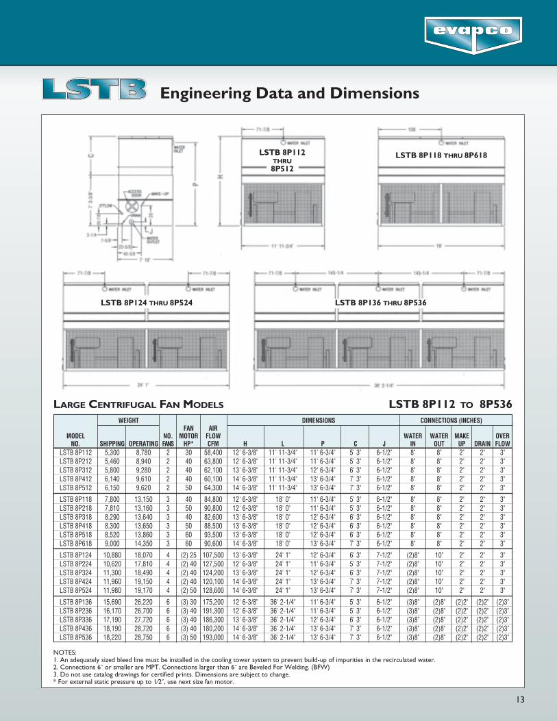
13
LARGE CENTRIFUGAL FAN MODELS LSTB 8P112 TO 8P536
NOTES:1. An adequately sized bleed line must be installed in the cooling tower system to prevent build-up of impurities in the recirculated water.2. Connections 6˝ or smaller are MPT. Connections larger than 6˝ are Beveled For Welding. (BFW)3. Do not use catalog drawings for certified prints. Dimensions are subject to change.* For external static pressure up to 1⁄2˝, use next size fan motor.
WEIGHT DIMENSIONS CONNECTIONS (INCHES)FAN AIR
MODEL NO. MOTOR FLOW WATER WATER MAKE OVERNO. SHIPPING OPERATING FANS HP* CFM H L P C J IN OUT UP DRAIN FLOW
LSTB 8P112 5,300 8,780 2 30 58,400 12' 6-3/8" 11' 11-3/4" 11' 6-3/4" 5' 3" 6-1/2" 8" 8" 2" 2" 3"LSTB 8P212 5,460 8,940 2 40 63,800 12' 6-3/8" 11' 11-3/4" 11' 6-3/4" 5' 3" 6-1/2" 8" 8" 2" 2" 3"LSTB 8P312 5,800 9,280 2 40 62,100 13' 6-3/8" 11' 11-3/4" 12' 6-3/4" 6' 3" 6-1/2" 8" 8" 2" 2" 3"LSTB 8P412 6,140 9,610 2 40 60,100 14' 6-3/8" 11' 11-3/4" 13' 6-3/4" 7' 3" 6-1/2" 8" 8" 2" 2" 3"LSTB 8P512 6,150 9,620 2 50 64,300 14' 6-3/8" 11' 11-3/4" 13' 6-3/4" 7' 3" 6-1/2" 8" 8" 2" 2" 3"
LSTB 8P118 7,800 13,150 3 40 84,800 12' 6-3/8" 18' 0" 11' 6-3/4" 5' 3" 6-1/2" 8" 8" 2" 2" 3"LSTB 8P218 7,810 13,160 3 50 90,800 12' 6-3/8" 18' 0" 11' 6-3/4" 5' 3" 6-1/2" 8" 8" 2" 2" 3"LSTB 8P318 8,290 13,640 3 40 82,600 13' 6-3/8" 18' 0" 12' 6-3/4" 6' 3" 6-1/2" 8" 8" 2" 2" 3"LSTB 8P418 8,300 13,650 3 50 88,500 13' 6-3/8" 18' 0" 12' 6-3/4" 6' 3" 6-1/2" 8" 8" 2" 2" 3"LSTB 8P518 8,520 13,860 3 60 93,500 13' 6-3/8" 18' 0" 12' 6-3/4" 6' 3" 6-1/2" 8" 8" 2" 2" 3"LSTB 8P618 9,000 14,350 3 60 90,600 14' 6-3/8" 18' 0" 13' 6-3/4" 7' 3" 6-1/2" 8" 8" 2" 2" 3"
LSTB 8P124 10,880 18,070 4 (2) 25 107,500 13' 6-3/8" 24' 1" 12' 6-3/4" 6' 3" 7-1/2" (2)8" 10" 2" 2" 3"LSTB 8P224 10,620 17,810 4 (2) 40 127,500 12' 6-3/8" 24' 1" 11' 6-3/4" 5' 3" 7-1/2" (2)8" 10" 2" 2" 3"LSTB 8P324 11,300 18,490 4 (2) 40 124,200 13' 6-3/8" 24' 1" 12' 6-3/4" 6' 3" 7-1/2" (2)8" 10" 2" 2" 3"LSTB 8P424 11,960 19,150 4 (2) 40 120,100 14' 6-3/8" 24' 1" 13' 6-3/4" 7' 3" 7-1/2" (2)8" 10" 2" 2" 3"LSTB 8P524 11,980 19,170 4 (2) 50 128,600 14' 6-3/8" 24' 1" 13' 6-3/4" 7' 3" 7-1/2" (2)8" 10" 2" 2" 3"
LSTB 8P136 15,690 26,220 6 (3) 30 175,200 12' 6-3/8" 36' 2-1/4" 11' 6-3/4" 5' 3" 6-1/2" (3)8" (2)8" (2)2" (2)2" (2)3"LSTB 8P236 16,170 26,700 6 (3) 40 191,300 12' 6-3/8" 36' 2-1/4" 11' 6-3/4" 5' 3" 6-1/2" (3)8" (2)8" (2)2" (2)2" (2)3"LSTB 8P336 17,190 27,720 6 (3) 40 186,300 13' 6-3/8" 36' 2-1/4" 12' 6-3/4" 6' 3" 6-1/2" (3)8" (2)8" (2)2" (2)2" (2)3"LSTB 8P436 18,190 28,720 6 (3) 40 180,200 14' 6-3/8" 36' 2-1/4" 13' 6-3/4" 7' 3" 6-1/2" (3)8" (2)8" (2)2" (2)2" (2)3"LSTB 8P536 18,220 28,750 6 (3) 50 193,000 14' 6-3/8" 36' 2-1/4" 13' 6-3/4" 7' 3" 6-1/2" (3)8" (2)8" (2)2" (2)2" (2)3"
Engineering Data and Dimensions
LSTB 8P112 THRU 8P512
LSTB 8P118 THRU 8P618
LSTB 8P124 THRU 8P524 LSTB 8P136 THRU 8P536
15723_LSTB Catalog 305 1/31/05 3:40 PM Page 13

Thermal Performance
MODELS LSTB 10112 TO 10636 Thermal performance certified by the Cooling TechnologyInstitute (CTI) in accordance with CTI Standard STD-201
† Mark Owned by the Cooling Technology Institute.
COOLING CAPACITY IN GPMTEMP °FEWT 90° 95° 90° 95° 90° 95° 90° 95° 95° 100°
MOTOR LWT 80° 80° 80° 80° 80° 80° 80° 80° 85° 85°MODEL NO. HP WB 66° 66° 68° 68° 70° 70° 72° 72° 75° 75°LSTB 10112 (1) 30 1253 979 1156 902 1026 808 894 718 1166 920LSTB 10212 (1) 40 1374 1078 1269 994 1129 893 986 794 1281 1014LSTB 10312 (1) 40 1432 1137 1328 1054 1187 953 1046 855 1339 1073LSTB 10412 (1) 50 1474 1161 1363 1071 1214 963 1062 858 1375 1092LSTB 10512 (1) 50 1533 1219 1422 1130 1272 1023 1121 919 1434 1151LSTB 10612 (1) 60 1620 1290 1503 1196 1346 1083 1187 974 1516 1218LSTB 10118 (2) 25 1734 1327 1589 1212 1395 1075 1201 945 1605 1238LSTB 10218 (2) 30 1846 1418 1696 1297 1491 1152 1285 1014 1712 1326LSTB 10318 (2) 25 1902 1487 1755 1370 1557 1227 1358 1091 1771 1397LSTB 10418 (2) 30 2017 1581 1863 1457 1655 1307 1445 1163 1880 1486LSTB 10518 (2) 30 2105 1670 1950 1548 1743 1399 1536 1255 1967 1576LSTB 10618 (2) 40 2209 1739 2043 1605 1819 1442 1591 1285 2061 1636LSTB 10718 (2) 40 2298 1827 2132 1694 1907 1534 1681 1377 2150 1725LSTB 10124 (2) 40 2519 1939 2316 1777 2039 1578 1760 1388 2338 1815LSTB 10224 (2) 40 2747 2156 2539 1989 2258 1786 1972 1589 2562 2028LSTB 10324 (2) 50 2947 2322 2727 2143 2429 1926 2125 1716 2751 2185LSTB 10424 (2) 50 3066 2438 2844 2261 2544 2046 2243 1838 2868 2301LSTB 10524 (2) 60 3240 2580 3007 2393 2692 2167 2374 1948 3032 2436LSTB 10136 (3) 40 3779 2909 3473 2665 3058 2367 2640 2083 3507 2722LSTB 10236 (3) 40 4121 3235 3808 2983 3386 2679 2958 2383 3842 3042LSTB 10336 (3) 50 4421 3482 4090 3214 3643 2889 3187 2574 4126 3277LSTB 10436 (3) 50 4600 3657 4266 3391 3816 3070 3364 2757 4302 3452LSTB 10536 (3) 60 4861 3870 4510 3589 4039 3250 3561 2922 4549 3654LSTB 10636 (3) 75 5199 4146 4826 3847 4325 3485 3817 3136 4867 3917
14
COOLING CAPACITY IN GPMTEMP °FEWT 95° 100° 95° 97° 100° 102° 95° 97° 100° 102°
MOTOR LWT 85° 85° 85° 87° 85° 87° 85° 87° 85° 87°MODEL NO. HP WB 76° 76° 78° 78° 78° 78° 80° 80° 80° 80°LSTB 10112 (1) 30 1100 869 953 1162 764 921 782 999 643 805LSTB 10212 (1) 40 1209 959 1050 1276 844 1016 863 1100 712 889LSTB 10312 (1) 40 1267 1019 1109 1334 906 1075 924 1158 773 949LSTB 10412 (1) 50 1299 1034 1131 1370 912 1094 932 1184 770 959LSTB 10512 (1) 50 1357 1093 1189 1429 972 1152 992 1242 831 1019LSTB 10612 (1) 60 1436 1157 1259 1511 1030 1220 1051 1314 881 1079LSTB 10118 (2) 25 1505 1164 1288 1598 1012 1241 1036 1357 838 1069LSTB 10218 (2) 30 1607 1246 1378 1705 1084 1328 1110 1449 898 1146LSTB 10318 (2) 25 1670 1320 1447 1764 1161 1399 1187 1518 977 1222LSTB 10418 (2) 30 1773 1405 1539 1873 1237 1488 1264 1613 1042 1301LSTB 10518 (2) 30 1861 1496 1629 1960 1329 1579 1357 1702 1134 1394LSTB 10618 (2) 40 1947 1548 1695 2054 1366 1639 1396 1774 1152 1436LSTB 10718 (2) 40 2035 1638 1782 2142 1457 1727 1487 1862 1245 1527LSTB 10124 (2) 40 2197 1706 1885 2328 1484 1818 1521 1982 1231 1571LSTB 10224 (2) 40 2418 1917 2100 2552 1689 2031 1727 2200 1423 1778LSTB 10324 (2) 50 2598 2067 2262 2741 1824 2188 1864 2368 1540 1917LSTB 10424 (2) 50 2715 2186 2378 2858 1945 2305 1985 2484 1661 2038LSTB 10524 (2) 60 2871 2314 2517 3021 2060 2440 2102 2629 1763 2158LSTB 10136 (3) 40 3295 2559 2827 3493 2227 2727 2282 2974 1847 2356LSTB 10236 (3) 40 3627 2876 3150 3828 2533 3047 2590 3300 2135 2667LSTB 10336 (3) 50 3897 3101 3393 4111 2736 3282 2796 3552 2309 2876LSTB 10436 (3) 50 4072 3278 3567 4287 2917 3457 2977 3726 2492 3057LSTB 10536 (3) 60 4307 3471 3776 4532 3091 3660 3153 3943 2644 3237LSTB 10636 (3) 75 4610 3721 4046 4849 3314 3923 3381 4224 2839 3471
To Make a Selection:Locate the column with the desired operating temperature conditions. Read down the column until you find the GPM equal to orgreater than the flow required. Read horizontally to the left to find the model number of the unit that will perform the duty.
Note: For alternate selections and conditions other than those stated, consult your iES selection program or local EVAPCO representative.
†
15723_LSTB Catalog 305 1/31/05 3:41 PM Page 14
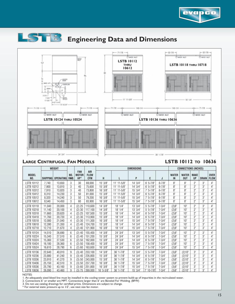
LARGE CENTRIFUGAL FAN MODELS LSTB 10112 TO 10636
NOTES:1. An adequately sized bleed line must be installed in the cooling tower system to prevent build-up of impurities in the recirculated water.2. Connections 6˝ or smaller are MPT. Connections larger than 6˝ are Beveled For Welding. (BFW)3. Do not use catalog drawings for certified prints. Dimensions are subject to change.* For external static pressure up to 1⁄2˝, use next size fan motor.
WEIGHT DIMENSIONS CONNECTIONS (INCHES)FAN AIR
MODEL NO. MOTOR FLOW WATER WATER MAKE OVERNO. SHIPPING OPERATING FANS HP* CFM H L P C J IN OUT UP DRAIN FLOW
LSTB 10112 7,740 13,650 3 30 69,000 15' 3/8" 11' 11-5/8" 14' 3/4" 6' 5-7/8" 6-7/8" 8" 8" 2" 3" 4"LSTB 10212 7,900 13,810 3 40 75,600 15' 3/8" 11' 11-5/8" 14' 3/4" 6' 5-7/8" 6-7/8" 8" 8" 2" 3" 4"LSTB 10312 7,910 13,820 3 40 73,800 16' 3/8" 11' 11-5/8" 15' 3/4" 7' 5-7/8" 6-7/8" 8" 8" 2" 3" 4"LSTB 10412 8,310 14,230 3 50 81,000 15' 3/8" 11' 11-5/8" 14' 3/4" 6' 5-7/8" 6-7/8" 8" 8" 2" 3" 4"LSTB 10512 8,320 14,240 3 50 79,200 16' 3/8" 11' 11-5/8" 15' 3/4" 7' 5-7/8" 6-7/8" 8" 8" 2" 3" 4"LSTB 10612 8,540 14,450 3 60 83,900 16' 3/8" 11' 11-5/8" 15' 3/4" 7' 5-7/8" 6-7/8" 8" 8" 2" 3" 4"
LSTB 10118 11,040 20,000 4 (2) 25 110,600 14' 3/8" 18' 1/4" 13' 3/4" 5' 5-7/8" 7-3/4" (2)8" 10" 2" 3" 4"LSTB 10218 11,140 20,100 4 (2) 30 117,100 14' 3/8" 18' 1/4" 13' 3/4" 5' 5-7/8" 7-3/4" (2)8" 10" 2" 3" 4"LSTB 10318 11,660 20,620 4 (2) 25 107,500 15' 3/8" 18' 1/4" 14' 3/4" 6' 5-7/8" 7-3/4" (2)8" 10" 2" 3" 4"LSTB 10418 11,760 20,720 4 (2) 30 113,900 15' 3/8" 18' 1/4" 14' 3/4" 6' 5-7/8" 7-3/4" (2)8" 10" 2" 3" 4"LSTB 10518 12,080 21,040 4 (2) 30 111,300 16' 3/8" 18' 1/4" 15' 3/4" 7' 5-7/8" 7-3/4" (2)8" 10" 2" 3" 4"LSTB 10618 12,390 21,350 4 (2) 40 124,700 15' 3/8" 18' 1/4" 14' 3/4" 6' 5-7/8" 7-3/4" (2)8" 10" 2" 3" 4"LSTB 10718 12,710 21,670 4 (2) 40 121,900 16' 3/8" 18' 1/4" 15' 3/4" 7' 5-7/8" 7-3/4" (2)8" 10" 2" 3" 4"
LSTB 10124 14,510 26,690 6 (2) 40 155,400 14' 3/8" 24' 3/4" 13' 3/4" 5' 5-7/8" 7-3/4" (2)8" 10" 2" 3" 4"LSTB 10224 15,340 27,510 6 (2) 40 151,200 15' 3/8" 24' 3/4" 14' 3/4" 6' 5-7/8" 7-3/4" (2)8" 10" 2" 3" 4"LSTB 10324 15,360 27,530 6 (2) 50 162,000 15' 3/8" 24' 3/4" 14' 3/4" 6' 5-7/8" 7-3/4" (2)8" 10" 2" 3" 4"LSTB 10424 16,180 28,360 6 (2) 50 158,400 16' 3/8" 24' 3/4" 15' 3/4" 7' 5-7/8" 7-3/4" (2)8" 10" 2" 3" 4"LSTB 10524 16,610 28,790 6 (2) 60 163,600 16' 3/8" 24' 3/4" 15' 3/4" 7' 5-7/8" 7-3/4" (2)8" 10" 2" 3" 4"
LSTB 10136 22,640 40,010 9 (3) 40 233,100 14' 3/8" 36' 1-7/8" 13' 3/4" 5' 5-7/8" 7-3/4" (3)8" (2)10" 3" 3" 4"LSTB 10236 23,880 41,240 9 (3) 40 226,800 15' 3/8" 36' 1-7/8" 14' 3/4" 6' 5-7/8" 7-3/4" (3)8" (2)10" 3" 3" 4"LSTB 10336 23,910 41,270 9 (3) 50 243,000 15' 3/8" 36' 1-7/8" 14' 3/4" 6' 5-7/8" 7-3/4" (3)8" (2)10" 3" 3" 4"LSTB 10436 25,150 42,510 9 (3) 50 237,700 16' 3/8" 36' 1-7/8" 15' 3/4" 7' 5-7/8" 7-3/4" (3)8" (2)10" 3" 3" 4"LSTB 10536 25,790 43,160 9 (3) 60 251,800 16' 3/8" 36' 1-7/8" 15' 3/4" 7' 5-7/8" 7-3/4" (3)8" (2)10" 3" 3" 4"LSTB 10636 26,090 43,460 9 (3) 75 269,000 16' 5-3/8" 36' 1-7/8" 15' 3/4" 7' 10-7/8" 7-3/4" (3)8" (2)10" 3" 3" 4"
Engineering Data and Dimensions
15
LSTB 10112 THRU 10612
LSTB 10136 THRU 10636
LSTB 10118 THRU 10718
LSTB 10124 THRU 10524
15723_LSTB Catalog 305 1/31/05 3:41 PM Page 15
5M/0105/YGS Bulletin 305
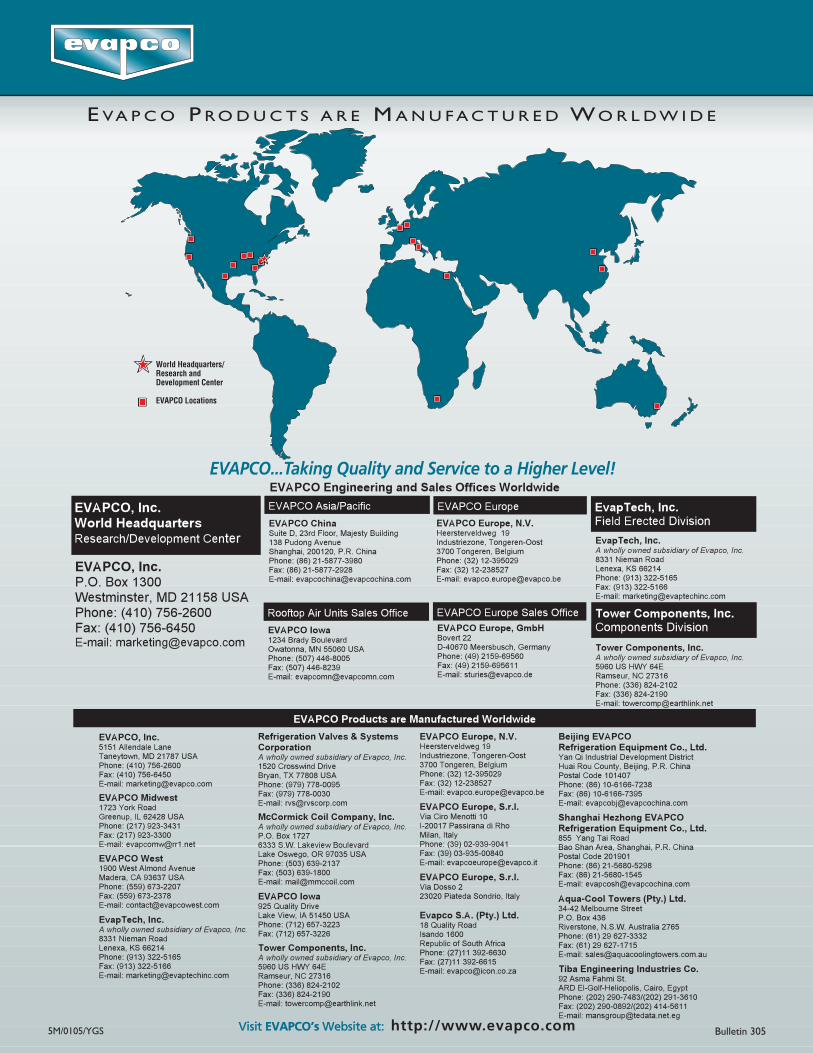
E VA P C O P R O D U C T S A R E M A N U F A C T U R E D WO R L D W I D E
EVAPCO, Inc.P.O. Box 1300 Westminster, MD 21158 USA Phone: (410) 756-2600 Fax: (410) 756-6450 E-mail: [email protected]
EVAPCO ChinaSuite D, 23rd Floor, Majesty Building 138 Pudong Avenue Shanghai, 200120, P.R. China Phone: (86) 21-5877-3980 Fax: (86) 21-5877-2928 E-mail: [email protected]
EVAPCO Europe, N.V.Heersterveldweg 19 Industriezone, Tongeren-Oost 3700 Tongeren, Belgium Phone: (32) 12-395029 Fax: (32) 12-238527 E-mail: [email protected]
EVAPCO Europe, GmbHBovert 22 D-40670 Meersbusch, Germany Phone: (49) 2159-69560 Fax: (49) 2159-695611 E-mail: [email protected]
EVAPCO, Inc.5151 Allendale Lane Taneytown, MD 21787 USA Phone: (410) 756-2600 Fax: (410) 756-6450 E-mail: [email protected]
EVAPCO Midwest1723 York Road Greenup, IL 62428 USA Phone: (217) 923-3431 Fax: (217) 923-3300 E-mail: [email protected]
EVAPCO West1900 West Almond Avenue Madera, CA 93637 USA Phone: (559) 673-2207 Fax: (559) 673-2378 E-mail: [email protected]
EVAPCO Iowa925 Quality Drive Lake View, IA 51450 USA Phone: (712) 657-3223 Fax: (712) 657-3226
Refrigeration Valves & Systems CorporationA wholly owned subsidiary of Evapco, Inc. 1520 Crosswind Drive Bryan, TX 77808 USA Phone: (979) 778-0095 Fax: (979) 778-0030 E-mail: [email protected]
McCormick Coil Company, Inc.A wholly owned subsidiary of Evapco, Inc. P.O. Box 1727 6333 S.W. Lakeview Boulevard Lake Oswego, OR 97035 USA Phone: (503) 639-2137 Fax: (503) 639-1800 E-mail: [email protected]
EVAPCO Europe, N.V.Heersterveldweg 19 Industriezone, Tongeren-Oost 3700 Tongeren, Belgium Phone: (32) 12-395029 Fax: (32) 12-238527 E-mail: [email protected]
EVAPCO Europe, S.r.l.Via Ciro Menotti 10 I-20017 Passirana di Rho Milan, Italy Phone: (39) 02-939-9041 Fax: (39) 03-935-00840 E-mail: [email protected]
Evapco S.A. (Pty.) Ltd.18 Quality Road Isando 1600 Republic of South Africa Phone: (27)11 392-6630 Fax: (27)11 392-6615 E-mail: [email protected]
Aqua-Cool Towers (Pty.) Ltd.34-42 Melbourne Street P.O. Box 436 Riverstone, N.S.W. Australia 2765 Phone: (61) 29 627-3332 Fax: (61) 29 627-1715 E-mail: [email protected]
Tiba Engineering Industries Co.92 Asma Fahmi St. ARD El-Golf-Heliopolis, Cairo, Egypt Phone: (202) 290-7483/(202) 291-3610 Fax: (202) 290-0892/(202) 414-5611 E-mail: [email protected]
EVAPCO Europe, S.r.l.Via Dosso 2 23020 Piateda Sondrio, Italy
EvapTech, Inc.A wholly owned subsidiary of Evapco, Inc. 8331 Nieman Road Lenexa, KS 66214 Phone: (913) 322-5165 Fax: (913) 322-5166 E-mail: [email protected]
Beijing EVAPCO Refrigeration Equipment Co., Ltd.Yan Qi Industrial Development District Huai Rou County, Beijing, P.R. China Postal Code 101407 Phone: (86) 10-6166-7238 Fax: (86) 10-6166-7395 E-mail: [email protected]
EVAPCO Iowa1234 Brady Boulevard Owatonna, MN 55060 USA Phone: (507) 446-8005 Fax: (507) 446-8239 E-mail: [email protected]
Shanghai Hezhong EVAPCO Refrigeration Equipment Co., Ltd.855 Yang Tai Road Bao Shan Area, Shanghai, P.R. China Postal Code 201901 Phone: (86) 21-5680-5298 Fax: (86) 21-5680-1545 E-mail: [email protected]
EVAPCO, Inc. World Headquarters Research/Development Center
EVAPCO Asia/Pacific EVAPCO Europe
EVAPCO Europe Sales Office
EvapTech, Inc. Field Erected Division
EVAPCO Products are Manufactured Worldwide
Rooftop Air Units Sales Office
Tower Components, Inc.A wholly owned subsidiary of Evapco, Inc. 5960 US HWY 64E Ramseur, NC 27316 Phone: (336) 824-2102 Fax: (336) 824-2190 E-mail: [email protected]
Tower Components, Inc. Components Division
EvapTech, Inc.A wholly owned subsidiary of Evapco, Inc. 8331 Nieman Road Lenexa, KS 66214 Phone: (913) 322-5165 Fax: (913) 322-5166 E-mail: [email protected]
Tower Components, Inc.A wholly owned subsidiary of Evapco, Inc. 5960 US HWY 64E Ramseur, NC 27316 Phone: (336) 824-2102 Fax: (336) 824-2190 E-mail: [email protected]
EVAPCO Engineering and Sales Offices Worldwide
World Headquarters/Research and Development Center
EVAPCO Locations
EVAPCO...Taking Quality and Service to a Higher Level!
Visit EVAPCO’s Website at: http://www.evapco.com
15723_LSTB Catalog 305 1/31/05 3:42 PM Page 16


