89
NEW SHALE WELL STIMULATION SYSTEM DR. WILLIAM MAURER Maurer Engineering Inc Austin, TX January 1, 2016
NEW SHALE WELL STIMULATION SYSTEM
DR. WILLIAM MAURER
Maurer Engineering Inc
Austin, TX
January 1, 2016

Use FULL SCREEN or SLIDE SHOW for better viewing
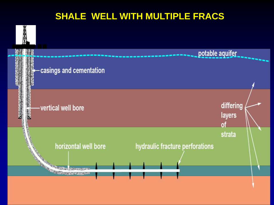
SHALE WELL WITH MULTIPLE FRACS

Problems with Shale Fracs & Refracs
•10 to 15 percent of fracs are non productive
• Near-wellbore damage initially reduces flow rates reduced 20 to 30 percent
• Wells Decline 50% first year and 70% after second year
• Refracing stimulates less than 50% of fracs in many wells
• Refracing is expensive and not reliable
Natural Fractures in Shale

Lateral Heterogeneity (macro scale)?
• If natural fissures are a significant component of fluid
flow in the formation… How are they distributed?
Can we avoid damaging them?
Single PlaneHC expulsion fissures
lacking well-developed
conjugate set (Leigh
Price, Bakken)
Conjugatelike we envision in CBM (face
and butt cleats) or Barnett
Shale
SwarmsSPE82212
James LimeVINCENT 2010A
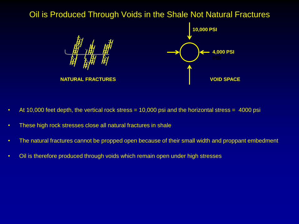
Oil is Produced Through Voids in the Shale Not Natural Fractures
• At 10,000 feet depth, the vertical rock stress = 10,000 psi and the horizontal stress = 4000 psi
• These high rock stresses close all natural fractures in shale
• The natural fractures cannot be propped open because of their small width and proppant embedment
• Oil is therefore produced through voids which remain open under high stresses
10,000 PSI
4,000 PSI
PSI
NATURAL FRACTURES VOID SPACE

Void Spaces in Shale
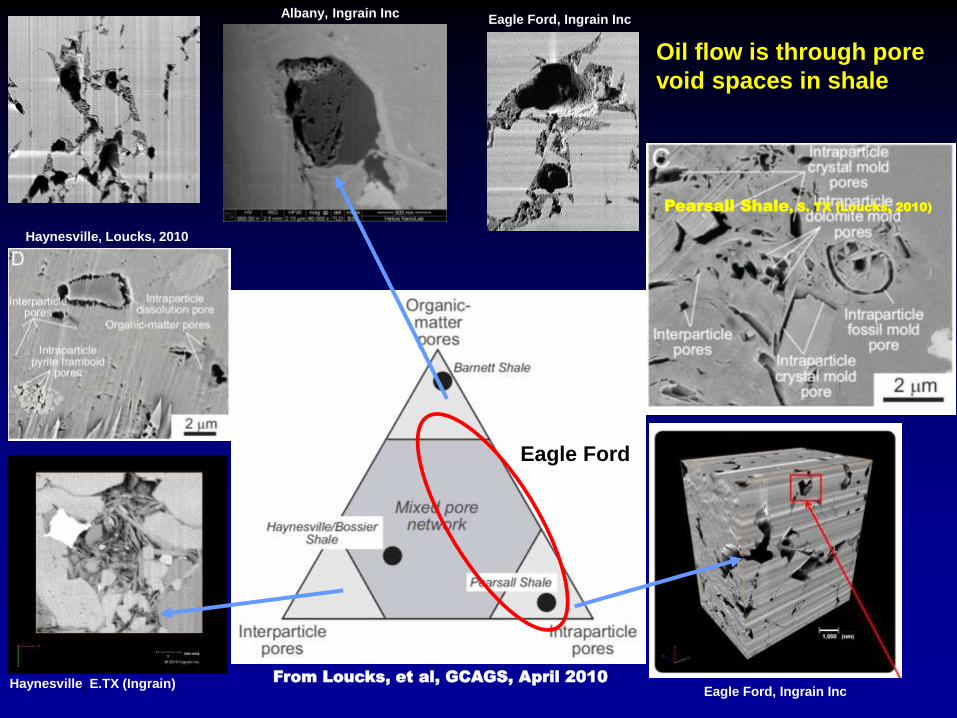
Eagle Ford
Pearsall Shale, S. TX (Loucks, 2010)
Eagle Ford, Ingrain IncAlbany, Ingrain Inc
Haynesville, Loucks, 2010
Haynesville, E.TX (Ingrain) From Loucks, et al, GCAGS, April 2010
Eagle Ford, Ingrain Inc
Oil flow is through pore
void spaces in shale
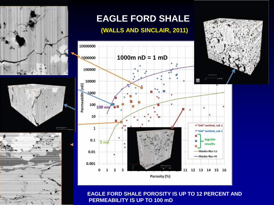
EAGLE FORD SHALE
(WALLS AND SINCLAIR, 2011)
1000m nD = 1 mD
EAGLE FORD SHALE POROSITY IS UP TO 12 PERCENT AND
PERMEABILITY IS UP TO 100 mD
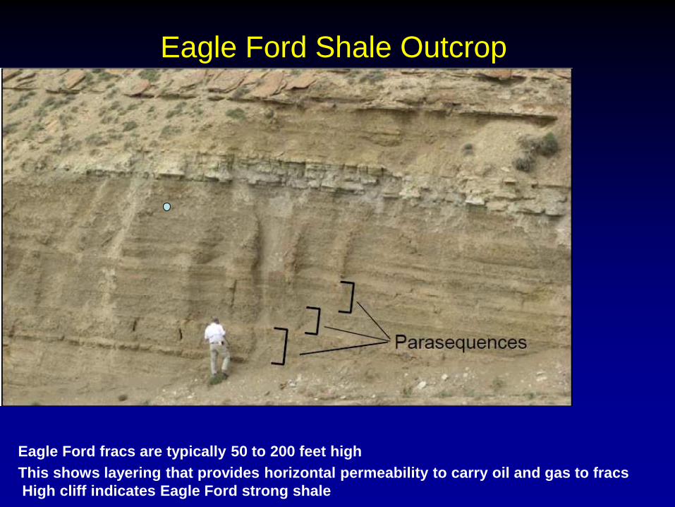
Eagle Ford Shale Outcrop
Eagle Ford fracs are typically 50 to 200 feet high
This shows layering that provides horizontal permeability to carry oil and gas to fracs
High cliff indicates Eagle Ford strong shale
Factors Causing Near-Wellbore Damage

FRAC PLUGGING IS NOT MAJOR PROBLEM WITH VERTICAL WELLS
Laminar flow
• Long Inflow area into fraced vertical wells reduces frac plugging
iInflow
50 FT
1000 ft
Vertical
Well
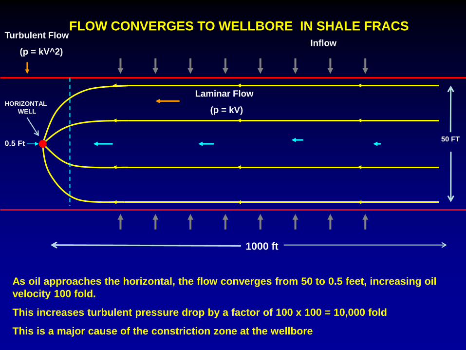
FLOW CONVERGES TO WELLBORE IN SHALE FRACS
0.5 Ft
Turbulent Flow
(p = kV^2)
Laminar Flow
(p = kV)
As oil approaches the horizontal, the flow converges from 50 to 0.5 feet, increasing oil
velocity 100 fold.
This increases turbulent pressure drop by a factor of 100 x 100 = 10,000 fold
This is a major cause of the constriction zone at the wellbore
iInflow
HORIZONTAL
WELL
50 FT
1000 ft

PLUGGING IN MAIN PART OF FRAC NOT A PROBLEM
0.5 Ft
Turbulent Flow
Laminar Flow
• Plugs in the tall part of frac have little effect because oil or gas flow
around them with minimum pressure drop
iInflow
Horizontal
Well
50 FT
1000 ft
PLUGS
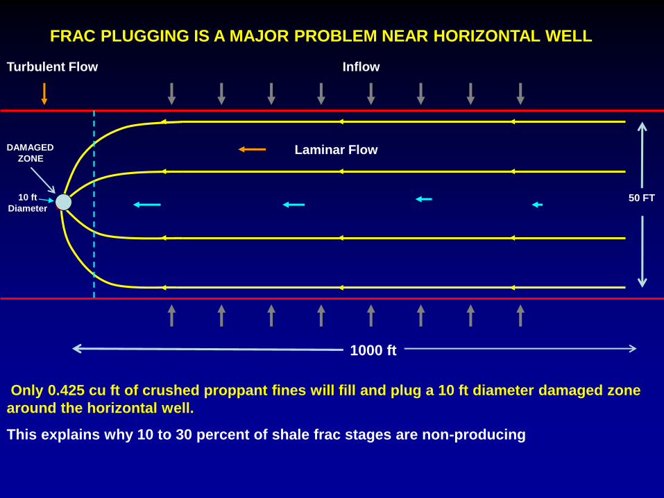
FRAC PLUGGING IS A MAJOR PROBLEM NEAR HORIZONTAL WELL
10 ft
Diameter
Turbulent Flow
Laminar Flow
Only 0.425 cu ft of crushed proppant fines will fill and plug a 10 ft diameter damaged zone
around the horizontal well.
This explains why 10 to 30 percent of shale frac stages are non-producing
iInflow
DAMAGED
ZONE
50 FT
1000 ft
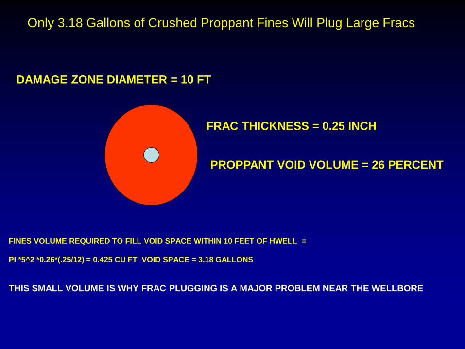
Only 3.18 Gallons of Crushed Proppant Fines Will Plug Large Fracs
DAMAGE ZONE DIAMETER = 10 FT
FINES VOLUME REQUIRED TO FILL VOID SPACE WITHIN 10 FEET OF HWELL =
PI *5^2 *0.26*(.25/12) = 0.425 CU FT VOID SPACE = 3.18 GALLONS
THIS SMALL VOLUME IS WHY FRAC PLUGGING IS A MAJOR PROBLEM NEAR THE WELLBORE
FRAC THICKNESS = 0.25 INCH
PROPPANT VOID VOLUME = 26 PERCENT

NEAR-WELLBORE CONSTRICTION ZONE

Multiple Small Fracs Initiate Parallel to Wellbore
Daneshy, 2011
SPE 140134
THIS IS CAUSED BY FRAC PRESSURE CHANGING THE STRESS STATE IN THE ROCK

Casing
σmax
σmax
Perfsσmin
σmin
Frac Propagation from Wellbore (Daneshy, 2011)
Fracture
THE FRACS ROTATE UNTIL THEY ARE PERPENDICULAR TO THE HORIZONTAL WELL
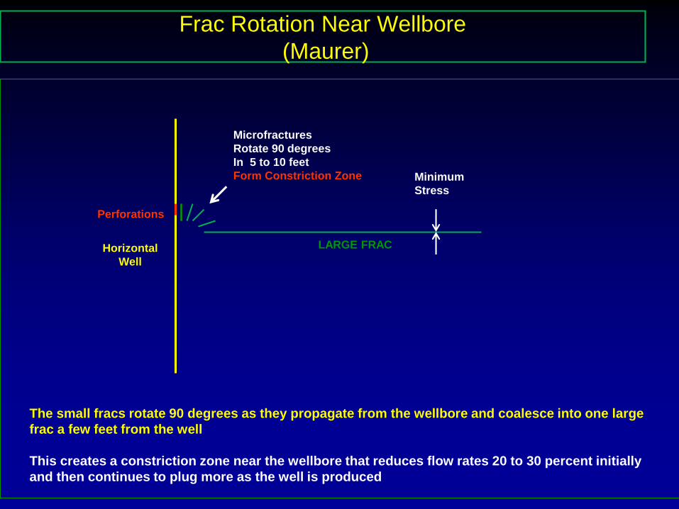
Frac Rotation Near Wellbore
(Maurer)
Minimum
Stress
LARGE FRACHorizontal
Well
Microfractures
Rotate 90 degrees
In 5 to 10 feet
Form Constriction Zone
Perforations
The small fracs rotate 90 degrees as they propagate from the wellbore and coalesce into one large
frac a few feet from the well
This creates a constriction zone near the wellbore that reduces flow rates 20 to 30 percent initially
and then continues to plug more as the well is produced

Near-Wellbore Damage Zone After Fracing
(Maurer)
(30% Flow Rate Reduction)
5 to10 Foot Radius Damaged Zone
Flow Restrictions
High Flow Velocities
Perforations
Fracture Initiation
High Pressure Drops
Fracture Plugging
OIL OR GAS Flow
FRAC
Horizontal well
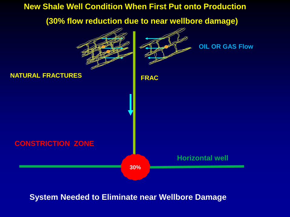
New Shale Well Condition When First Put onto Production
(30% flow reduction due to near wellbore damage)
CONSTRICTION ZONE
30%
OIL OR GAS Flow
FRAC
Horizontal well
NATURAL FRACTURES
System Needed to Eliminate near Wellbore Damage

Well Condition After Two Years
(70 % flow reduction – Uneconomical)
CONSTRICTION ZONE
(Gets Worse With Time)
70%
OIL OR GAS Flow
FRAC
Horizontal well
NATURAL FRACTURES
PROPPANT & FORMATION FINES
DECLINE DUE TO CONSTRICTION CONTINUING TO PLUG AS WELL IS PRODUCED
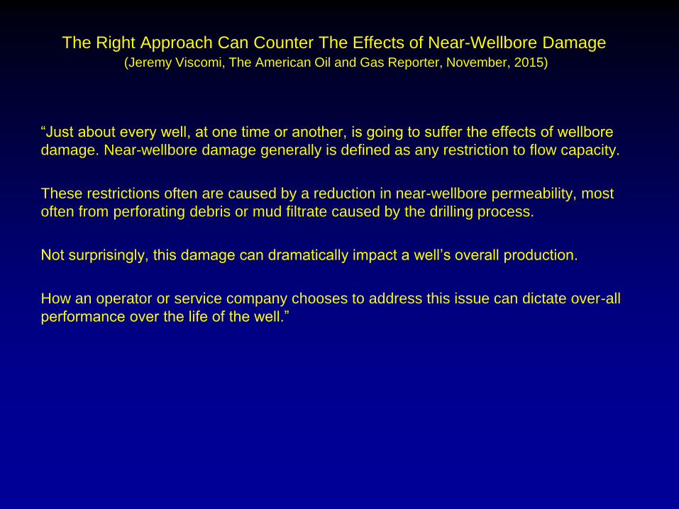
The Right Approach Can Counter The Effects of Near-Wellbore Damage(Jeremy Viscomi, The American Oil and Gas Reporter, November, 2015)
“Just about every well, at one time or another, is going to suffer the effects of wellbore
damage. Near-wellbore damage generally is defined as any restriction to flow capacity.
These restrictions often are caused by a reduction in near-wellbore permeability, most
often from perforating debris or mud filtrate caused by the drilling process.
Not surprisingly, this damage can dramatically impact a well’s overall production.
How an operator or service company chooses to address this issue can dictate over-all
performance over the life of the well.”

George King Comments on Near-wellbore damage (Jeremy Viscomi, The American Oil and Gas Reporter, November, 2015)
“The effect of the damage, the type of damage, severity of plugging, the depth, and the
ability to prevent, remove, or even bypass the damage are all key factors in an operator’s
strategy to address near-wellbore damage.
King asserts that shallow damage is the most common and that it takes a significant
amount of damage to reduce production drastically.
He says the problem is that generally, the highest permeability zones are the easiest to
damage and also are the ones that will cause the greatest reduction in production.
How one approaches cleanup can be a most useful tool in addressing the issue of near-
wellbore damage.”
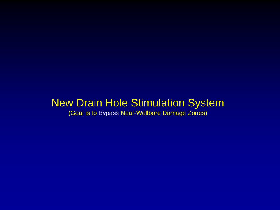
New Drain Hole Stimulation System(Goal is to Bypass Near-Wellbore Damage Zones)

Drain Holes Bypass Wellbore Damage Zones and Drill Across Fracs
FRAC
DRAIN HOLE
3 TO 4-3/4 INCH
HORIZONTAL WELL
DAMAGE ZONE
OIL
COMPLETED OPEN HOLE
Drain holes provide large flow paths to horizontal well
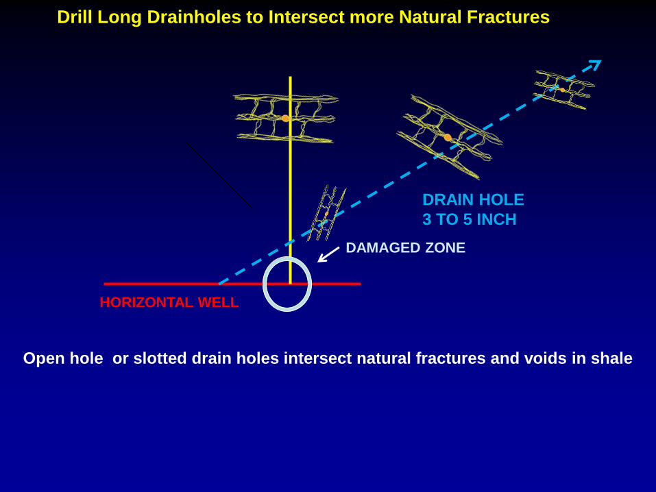
Drill Long Drainholes to Intersect more Natural Fractures
DRAIN HOLE
3 TO 5 INCH
HORIZONTAL WELL
DAMAGED ZONE
Open hole or slotted drain holes intersect natural fractures and voids in shale
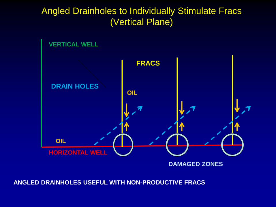
Angled Drainholes to Individually Stimulate Fracs
(Vertical Plane)
FRACS
DRAIN HOLES
HORIZONTAL WELL
DAMAGED ZONES
VERTICAL WELL
OIL
ANGLED DRAINHOLES USEFUL WITH NON-PRODUCTIVE FRACS
OIL
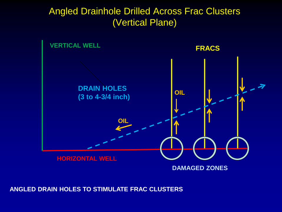
Angled Drainhole Drilled Across Frac Clusters
(Vertical Plane)
FRACS
DRAIN HOLES
(3 to 4-3/4 inch)
HORIZONTAL WELL
DAMAGED ZONES
VERTICAL WELL
OIL
ANGLED DRAIN HOLES TO STIMULATE FRAC CLUSTERS
OIL
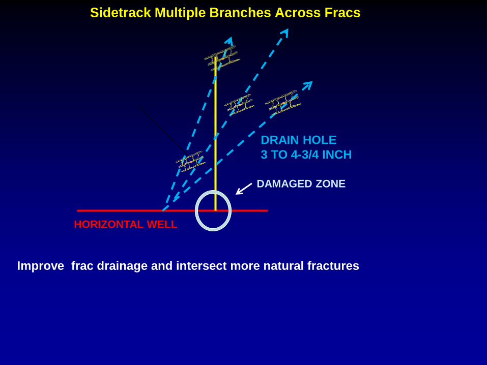
Sidetrack Multiple Branches Across Fracs
DRAIN HOLE
3 TO 4-3/4 INCH
HORIZONTAL WELL
DAMAGED ZONE
Improve frac drainage and intersect more natural fractures
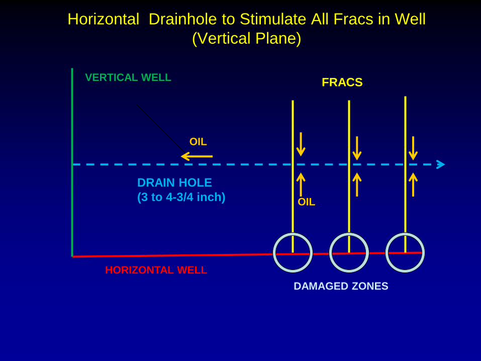
Horizontal Drainhole to Stimulate All Fracs in Well
(Vertical Plane)
FRACS
DRAIN HOLE
(3 to 4-3/4 inch)
HORIZONTAL WELL
DAMAGED ZONES
VERTICAL WELL
OIL
OIL
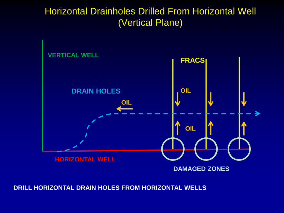
Horizontal Drainholes Drilled From Horizontal Well
(Vertical Plane)
FRACS
DRAIN HOLES
HORIZONTAL WELL
DAMAGED ZONES
VERTICAL WELL
OIL
OIL
OIL
DRILL HORIZONTAL DRAIN HOLES FROM HORIZONTAL WELLS
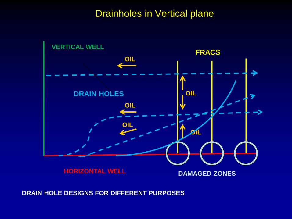
Drainholes in Vertical plane
FRACS
DRAIN HOLES
HORIZONTAL WELL DAMAGED ZONES
VERTICAL WELL
OIL
OIL
OIL
OIL
DRAIN HOLE DESIGNS FOR DIFFERENT PURPOSES
OIL

Drainholes Drilled in Horizontal Plane
FRACS
DRAIN HOLES
HORIZONTAL WELL
DAMAGED ZONES
VERTICAL
WELL
OIL
DRAINHOLES CAN BE LONGER IN HORIZONTAL PLANE
OIL

DRAINHOLE INDEPENDENT OF FRACED WELL (HEEL TO TOE)

DRAINHOLE INDEPENDENT OF FRACED WELL (TOE TO HEEL)
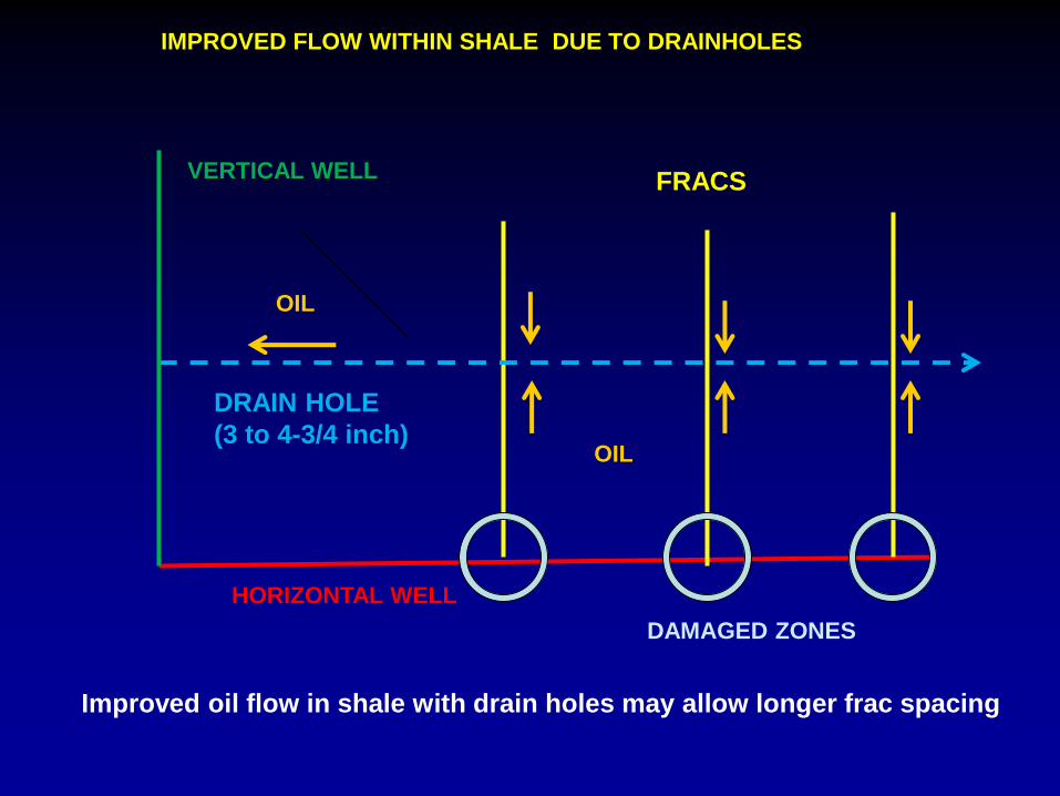
IMPROVED FLOW WITHIN SHALE DUE TO DRAINHOLES
FRACS
DRAIN HOLE
(3 to 4-3/4 inch)
HORIZONTAL WELL
DAMAGED ZONES
VERTICAL WELL
OIL
OIL
Improved oil flow in shale with drain holes may allow longer frac spacing
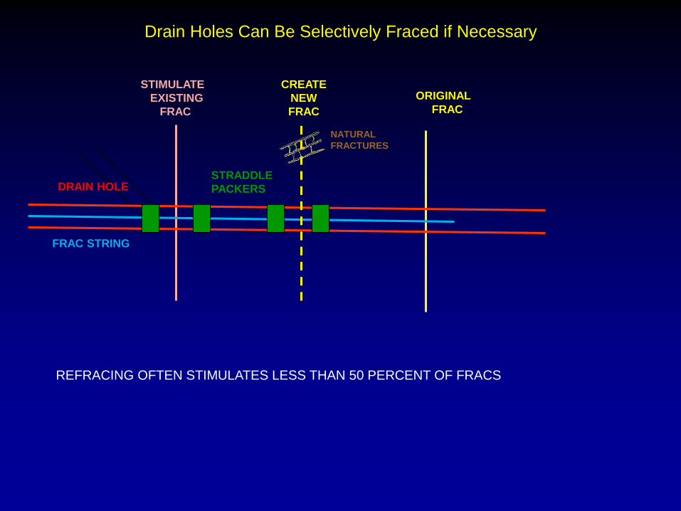
Drain Holes Can Be Selectively Fraced if Necessary
ORIGINAL
FRAC
STRADDLE
PACKERSDRAIN HOLE
STIMULATE
EXISTING
FRAC
CREATE
NEW
FRAC
FRAC STRING
NATURAL
FRACTURES
REFRACING OFTEN STIMULATES LESS THAN 50 PERCENT OF FRACS
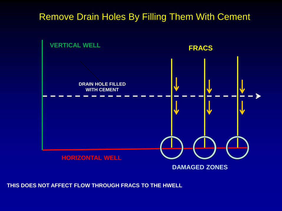
Remove Drain Holes By Filling Them With Cement
FRACS
DRAIN HOLE FILLED
WITH CEMENT
HORIZONTAL WELL
DAMAGED ZONES
VERTICAL WELL
THIS DOES NOT AFFECT FLOW THROUGH FRACS TO THE HWELL

Application Team
Concept and Patents
Well planning and Drilling Engineers
Instrumentation and
Candidate Well selection
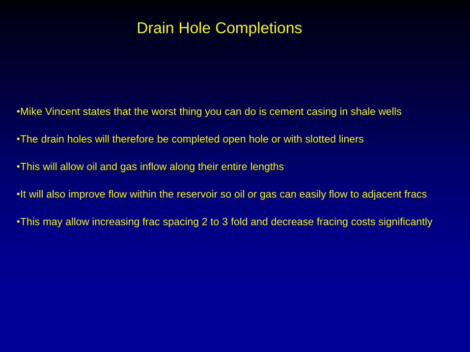
Drain Hole Completions
•Mike Vincent states that the worst thing you can do is cement casing in shale wells
•The drain holes will therefore be completed open hole or with slotted liners
•This will allow oil and gas inflow along their entire lengths
•It will also improve flow within the reservoir so oil or gas can easily flow to adjacent fracs
•This may allow increasing frac spacing 2 to 3 fold and decrease fracing costs significantly
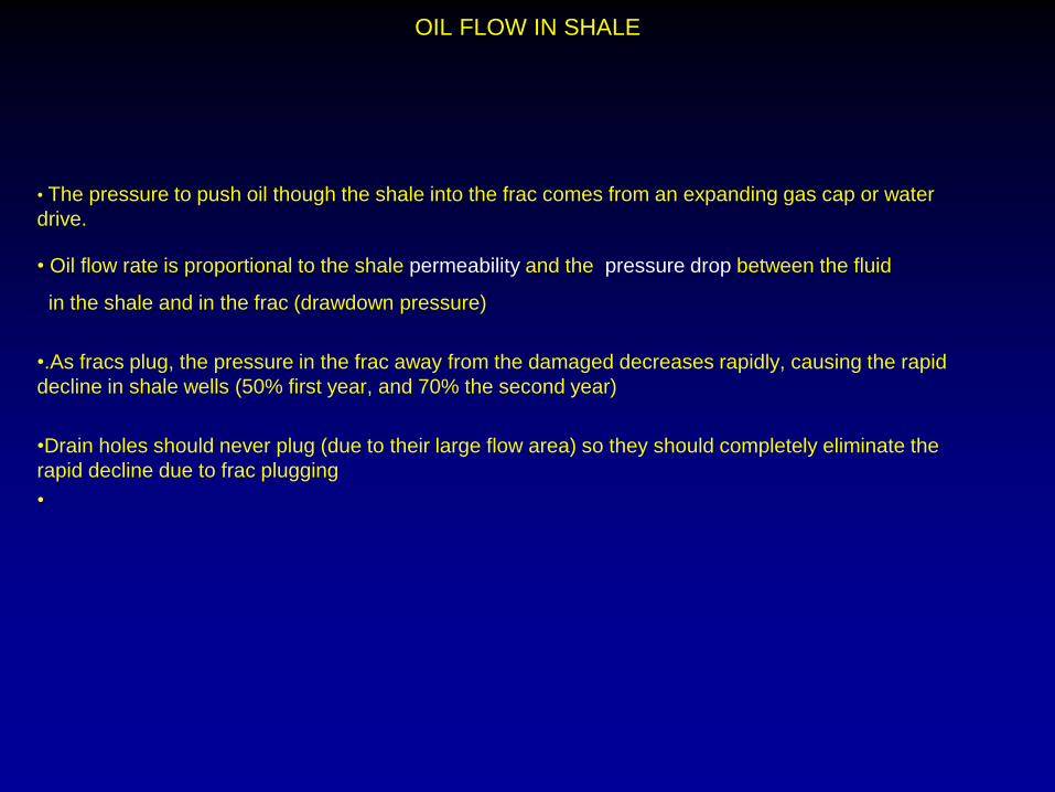
OIL FLOW IN SHALE
• The pressure to push oil though the shale into the frac comes from an expanding gas cap or water
drive.
• Oil flow rate is proportional to the shale permeability and the pressure drop between the fluid
in the shale and in the frac (drawdown pressure)
•.As fracs plug, the pressure in the frac away from the damaged decreases rapidly, causing the rapid
decline in shale wells (50% first year, and 70% the second year)
•Drain holes should never plug (due to their large flow area) so they should completely eliminate the
rapid decline due to frac plugging
•
Major Computer Simulation Problems

Vincent SPE 119143
SOPHISTICATED 3D MODELS OFTEN PRESUME• PLANAR FRACS
• HYDRAULIC CONTINUITY
IMAGE SOURCE SPE 110093
Problems with Frac Models (Vincent, 2010)
Frac models are incorrectly based on planar fracs with uniform conductivity
Frac models incorrectly assume pressure drops in fracs are proportional to
velocity (Laminar flow)
Fluid flow in frac is proportional to velocity squared near wellbore due to high
velocities and turbulent flow
This results in frac models greatly underestimating frac pressure drops near
wellbores
History matching frac curves provide little or no useful information
SPE 119143
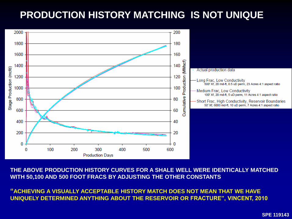
PRODUCTION HISTORY MATCHING IS NOT UNIQUE
THE ABOVE PRODUCTION HISTORY CURVES FOR A SHALE WELL WERE IDENTICALLY MATCHED
WITH 50,100 AND 500 FOOT FRACS BY ADJUSTING THE OTHER CONSTANTS
“ACHIEVING A VISUALLY ACCEPTABLE HISTORY MATCH DOES NOT MEAN THAT WE HAVE
UNIQUELY DETERMINED ANYTHING ABOUT THE RESERVOIR OR FRACTURE”, VINCENT, 2010

MAJOR REFRACING PROBLEM

Refracs Stimulate only 50% of Fracs (Kashikar and Jbeil)
June 2015 World Oil
On these two wells using diverters to isolate stages, less than 50% of the stages closest
to the “heel” were stimulated.
“This is a common occurrence where operators must rely on diverters to isolate perf
clusters”

SPINNER FLOW RATE SURVEYS

SPINNER FLOW METER SURVEYS
Spinner flow meter surveys should be used in
new and refraced wells
They give accurate measurements of the flow
from each frac
They provide the information needed for
operators to optimize fracing and refracing
operations
They helped MicroSeismic show that less than 50
percent of fracs are stimulated in many shale
wells

BP Recommends Using Trace Materials To
“Reveal Where the Proppant is placed”
Drain Holes Utilize only Conventional Drilling Equipment
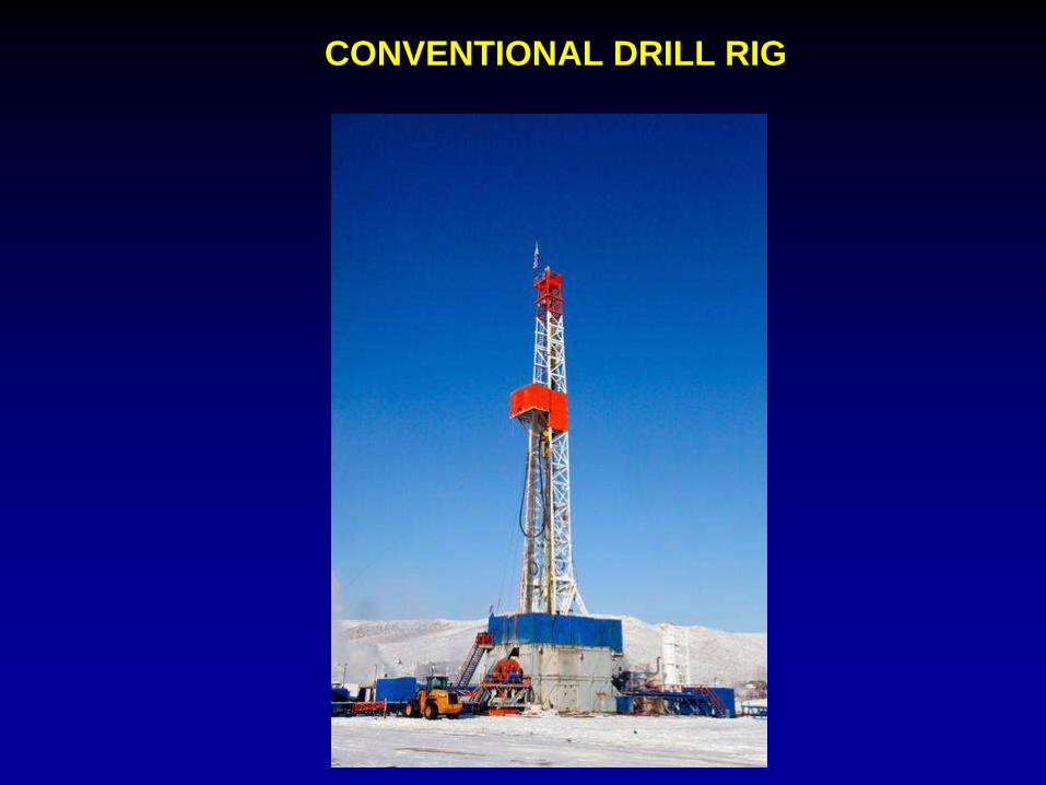
CONVENTIONAL DRILL RIG

COILED TUBING DRILLING (Optional)

Conventional Bent Housing Motor
DRILLS A CURVED HOLE WHEN MOTOR HOUSING NOT ROTATING
AND A STRAIGHT HOLE WHEN MOTOR HOUSING ROTATING

Conventional Rotary SteeringTool
Utilizes intermittent side pads to control direction while motor housing is rotating
Used primarily in long horizontal wells where high borehole friction limits well length
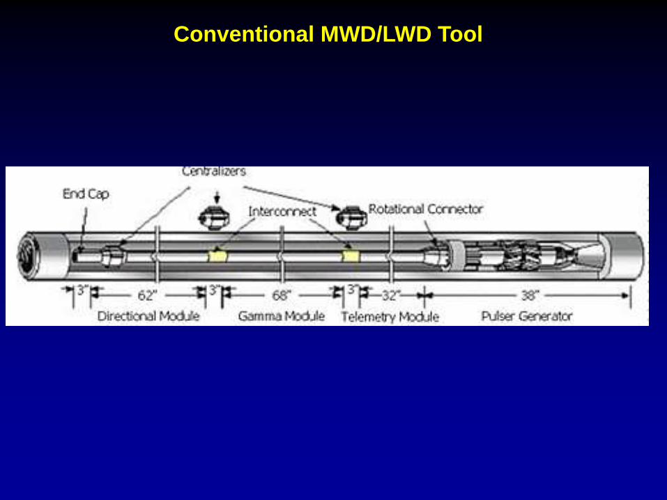
Conventional MWD/LWD Tool
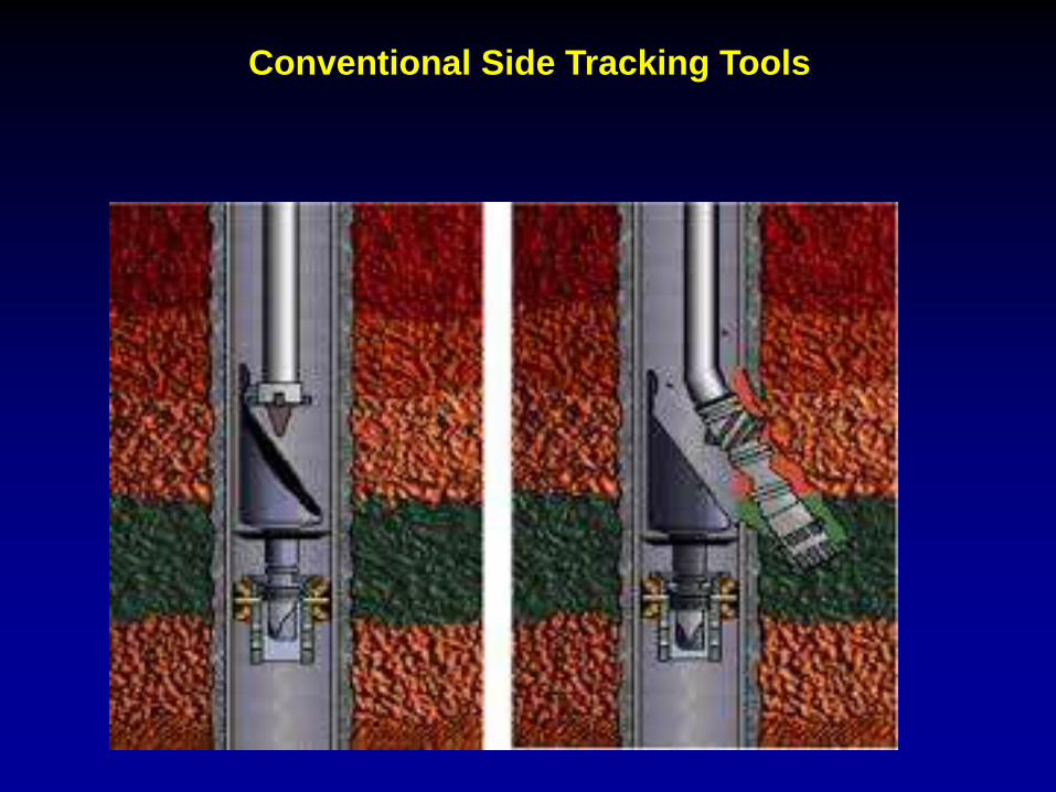
Conventional Side Tracking Tools

SAGD Parallel Drilling System (Optional)
HALLIBURTON.COM
Allows accurate control of spacing between wells

Using Stacked Rigs and Conventional Equipment will Allow Rapid
Implementation of Drain Holes

Eliminating Refracing Will Get Rid of the Following Problems

HIGH PRESSURE PUMPS

ELIMINATE REFACING AND HIGH COST AND LOGISTIC PROBLEMS
HIGH COSTS AND LOGISTICS PROBLEMS
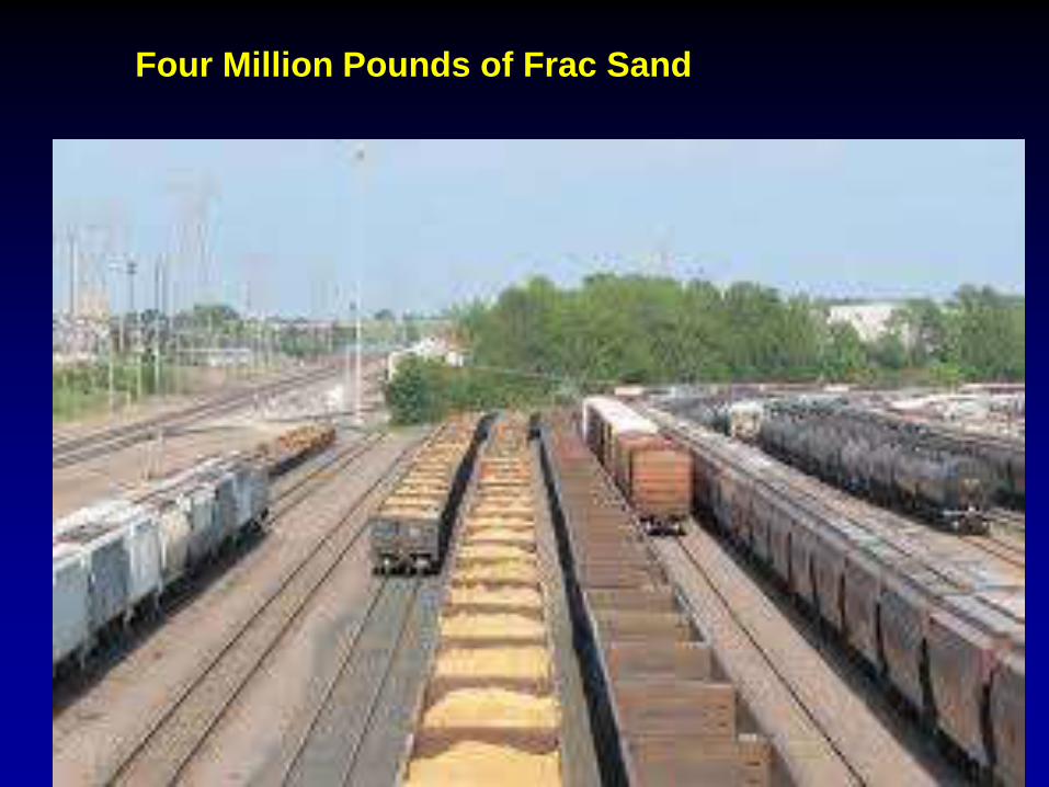
Four Million Pounds of Frac Sand
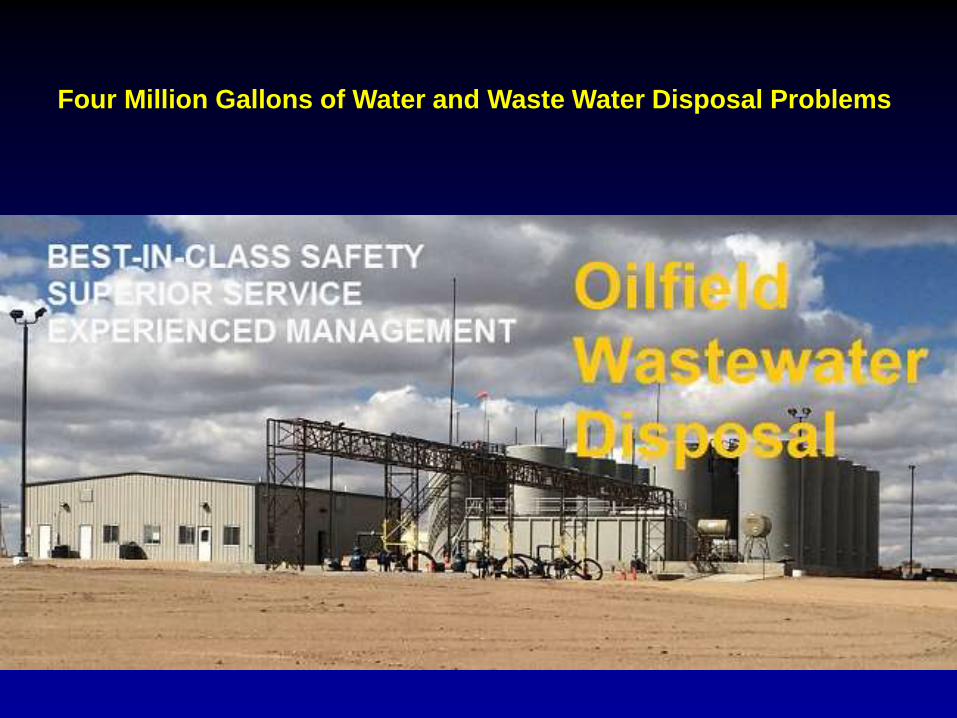
Four Million Gallons of Water and Waste Water Disposal Problems
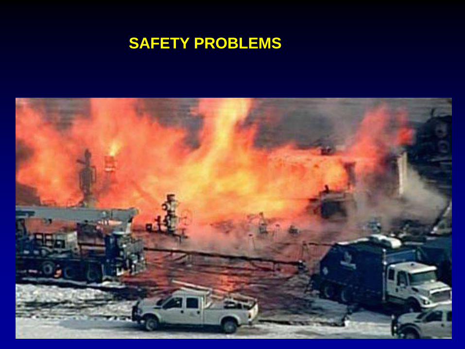
SAFETY PROBLEMS
Federal and State Fracing Regulations

Demonstrators

HIGH REFRACING COSTS
$$$$$$“PUMP AND PRAY”

Frac Expert Comments about Drain Holes
Factors Supporting Drain Hole Drilling
1 Reduced frac conductivity identified as major problem
3 Less than 50 percent of fracs are often stimulated by refracing
4 Near wellbore damage causes 50 to 70 percent decline rates
5 5 to10 percent of proppants are crushed in fracs and plug fracs
6 Refracing is very unreliable (“Pump and Pray)”

INDUSTRY FRACING EXPERT COMMENTS
“Many refracing successes are due to increasing frac
conductivity, not stimulating additional natural fractures”
Mike Vincent 2010
Mike Vincent Quotes
“Uneconomic refracs have been performed in almost every reserve type”
“There are myriad conditions that can cause refrac failures, each with its own best resolution”
“Pump and Pray”
Johnson, Kari: “Special Report: “Horizontal Well Operations”, July 2015 The American oil & Gas
Reporter

“Most of the refracs today are done without mechanical isolation, opening all
stages and perforation clusters to fluid flow and pressure simultaneously”
“Diverters are often not effective in isolating frac stages”
“Less than 50 percent of fracs are stimulated during many refracs”
Kashikar and Jbeil, MicroSeismic, Inc
World Oil, June 2015

SCHLUMBERGER EAGLE FORD REFRACING CONSORTIUM
Schlumberger and five Eagle Ford operators formed a refracing consortium in 2014
that set three refracing goals:
1. Increase Stimulated Reservoir Volume
2. Improve the Conductivity of Existing Frac
3. Re-energize a Parent Well before Completing an Infill Well Nearby
Cook, A and Clark, B: “Sequenced Refracing Technology Improves Economics in Unconventional
Plays”, JPT September, 2015
POTENTIAL BENEFITS OF DRAIN HOLE STIMULATION
• Bypass near-wellbore damaged zones and provide large flow paths
• Eliminate costly and troublesome refracing
• Stimulate all fracs at once
• Reduce stimulation costs 50 to 60 percent
• increase flow rates 30 to 70 percent
• Eliminate rapid decline
• Eliminate need to refrac every 2 to 3 years
Sanchez Offset Wells Problem(Kari Johnson, October, 2015)
• “While drilling new offset wells in the Eagle Ford, frac water is produced from all of
the surrounding offset wells for 30 to 60 days and they go back to producing oil and
gas at the previous rates with no loss in reserves”
• Maurer - This shows that there is high permeability within most commercial shale
fields

High Speed Drain Hole Jet Drilling System
(Future)
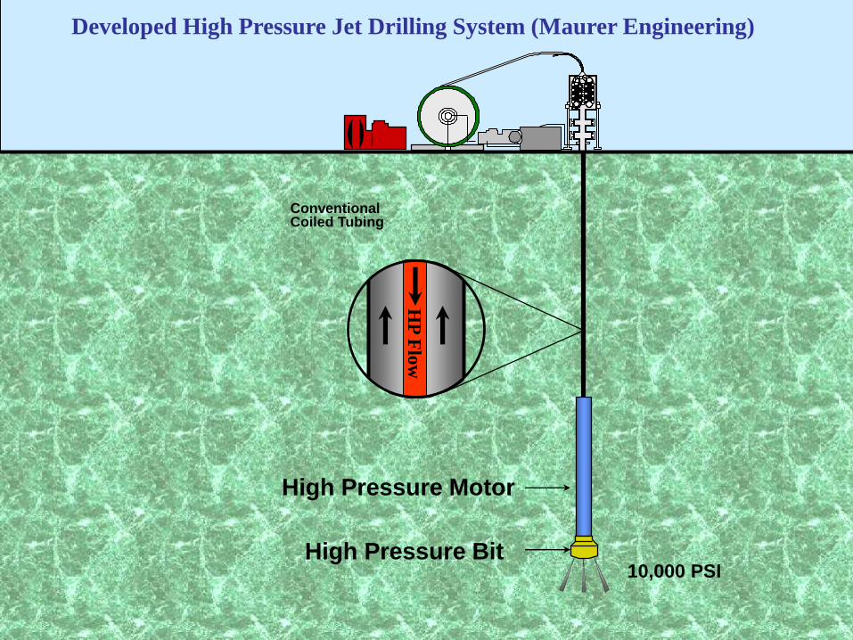
82
High Pressure Bit
HP
Flo
w
ConventionalCoiled Tubing
High Pressure Motor
Developed High Pressure Jet Drilling System (Maurer Engineering)
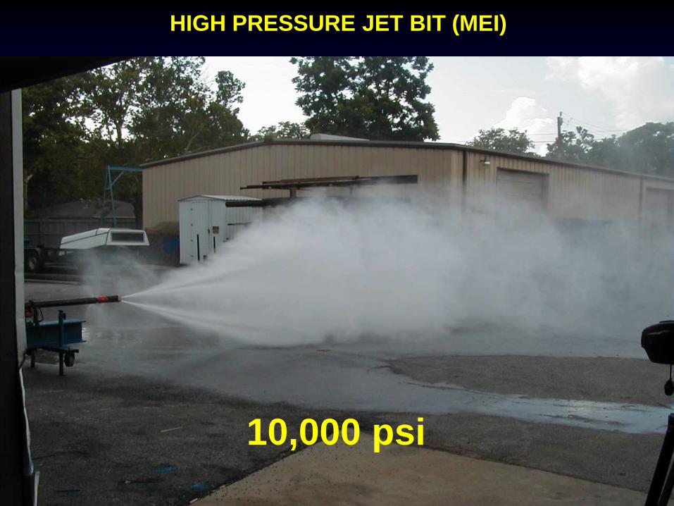
10,000 PSI

83
High-Pressure Coil (Med
Tubing Motor
10,000 PSI PDM MOTOR (MEI)
84
10,000 psi
HIGH PRESSURE JET BIT (MEI)
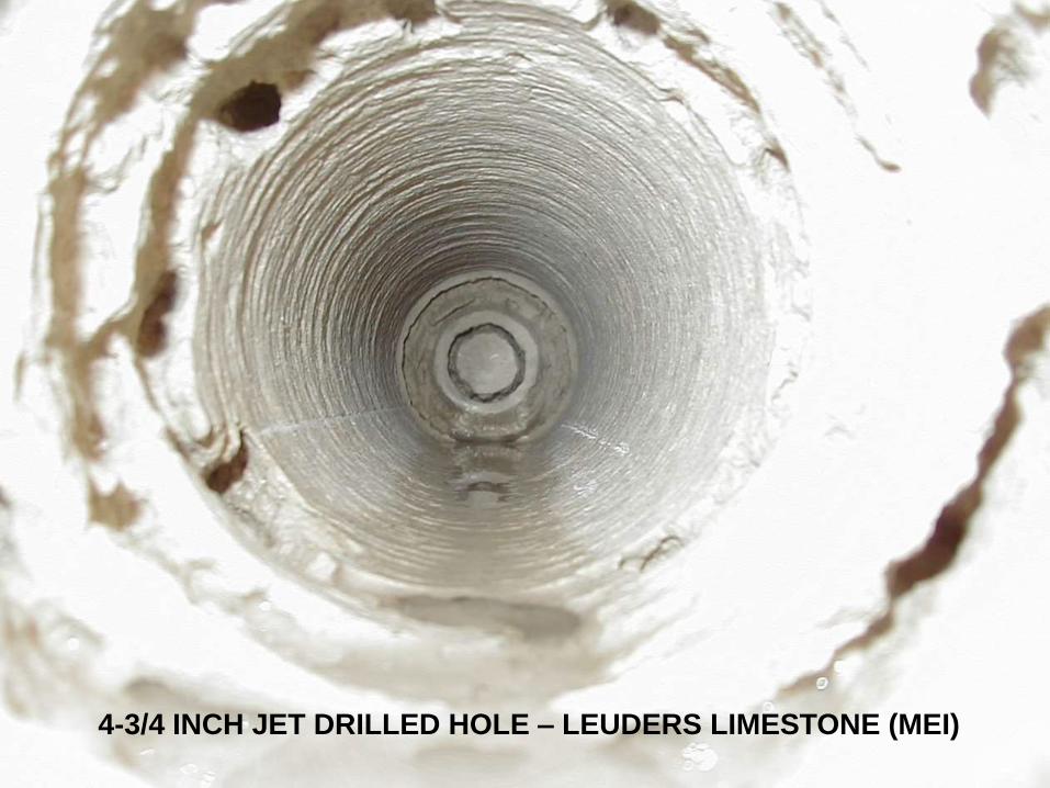
854-3/4 INCH JET DRILLED HOLE – LEUDERS LIMESTONE (MEI)
86
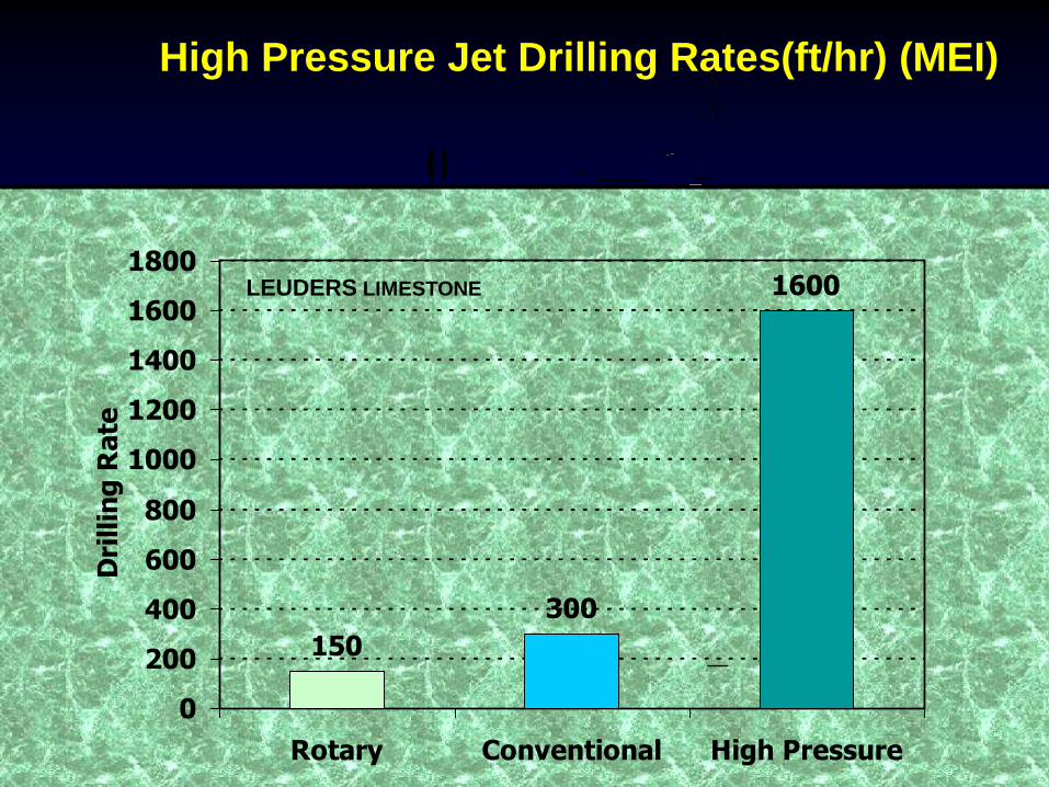
150
300
1600
0
200
400
600
800
1000
1200
1400
1600
1800
Rotary Conventional High Pressure
Dri
llin
g R
ate
High Pressure Jet Drilling Rates(ft/hr) (MEI)
LEUDERS LIMESTONE

EXTRA SLIDES
OIL FLOW IN SHALE
• Energy and pressure are required to push oil through the pores in the shale
• This energy comes from an expanding gas cap or water drive
• Most shale oil wells are water drive where the pressure in the formation equals that exerted by a column of water to the surface
• Therefore some water is typically water is produced with the oil
• Oil flow (Darcy Flow) is proportional to:
a. The drawdown pressure between the formation and the frac
b. The permeability of the formation
•. The drawdown pressure is decreased by the pressure drop in the frac so frac plugging is very detrimental to oil production
• Most of the rapid decline in shale wells is due to frac plugging near the wellbore decreasing drawdown pressures and flow rates by
50% to 70%
• The drain holes bypass these constriction zones and therefore increase production rates more than refracing
•
•