40
Jelle Gerard Wijnja Technology Manager Ethylene Furnaces Technip Benelux New Technologies in Ethylene Cracking Furnace Design Presentation for AIChE NL/B Zoetermeer, 31 October 2017
This document and all information herein are confidential, and may not be used, reproduced or distributed without prior authorization of TechnipFMC.
Jelle Gerard WijnjaTechnology Manager Ethylene FurnacesTechnip Benelux
New Technologies in Ethylene Cracking Furnace Design
Presentation for AIChE NL/BZoetermeer, 31 October 2017
22
Table of Contents
1. Introduction TechnipFMC2. Cracking Fundamentals3. Latest applied Technologies in Furnace Design

3
1. IntroductionTechnipFMC

4
TechnipFMC in a Snapshot
21Vessels
2Stock Exchange listings – NYSE
and Euronext Paris
48Countries in which
we operate
44,000Employees
A unique global leader in oil and gas projects, technologies, systems, and services that will enhance the performance of the world’s energy industry

5
Three Major Operating Segments
Subsea Onshore/Offshore Surface
A comprehensive and flexible offering from concept to project delivery and beyond
6
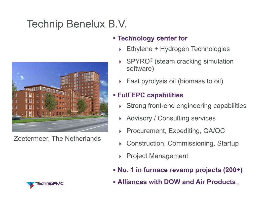
Technip Benelux B.V.
Zoetermeer, The Netherlands
Technology center for Ethylene + Hydrogen Technologies
SPYRO® (steam cracking simulation software)
Fast pyrolysis oil (biomass to oil)
Full EPC capabilities Strong front-end engineering capabilities
Advisory / Consulting services
Procurement, Expediting, QA/QC
Construction, Commissioning, Startup
Project Management
No. 1 in furnace revamp projects (200+)
Alliances with DOW and Air Products

7
Process Technology Centers Around the World
HoustonBoston/Weymouth
Claremont
Zoetermeer
RomeParis
London

8
Supply of ~400 Cracking Furnaces
Liquid FurnacesGK6®, USC-U® & SU®
> 200 furnaces
Gas FurnacesSMKTM, USC-M®
> 200 furnaces

99
2. Cracking FundamentalsCharacteristicsCracking FurnaceSPYRO® simulation software

10
Worldwide Ethylene Capacity
Current ethylene capacity 165 000 kta (2016)
271 steam cracking units in operation
Plant capacity ranging from 30 to almost 2000 kta
54 countries
Average growing ethylene capacity: 3.9% (recorded over the years)
Capacity is increased by
New grassroots plants
Plant expansions
Ethylene is the largest chemical produced worldwide

11
Characteristics of Olefins Production• Strongly endothermic process
Ethane• Absorbed duty: Q ~1.6 MW / ton of feed• For 1500 kta cracker: fired heat ~ 890 MW
Naphtha• Absorbed duty: Q ~1.4 MW / ton of feed• For 1000 kta cracker: fired heat ~ 790 MW
Feed Products
Heat

12
Cracking Reactions - Products
Example – ethane cracking
C2H6 CH3* + CH3* initiation reaction
CH3* + C2H6 CH4 + C2H5* hydrogen abstraction
C2H5* C2H4 + H* propagationH* + C2H6 CH4 + C2H5*
C2H5* + C2H5* C2H10 terminationH* + C2H5* C2H6H* + CH3* CH4H* + H* H2
Mass, dry% ethane Naphtha
Hydrogen 4.1 0.8
Methane 5.0 13.4
Acetylene 0.4 0.3
Ethylene 52.8 27.7
Ethane 32.6 3.8
C3H4’s 0.03 0.6
Propylene 1.2 16.4
Propane 0.2 0.5
sum C4’s 1.9 11.2
sum C5s 0.4 5.9
sum C6’s 0.9 8.1
sum C7’s 0.1 4.1
sum C8’s 0.1 2.2
sum C9’s 0.01 1.4
sum C10’s 0.2 3.4

15
Cracking - Coke formationHydrocarbons Olefins + other products + coke
Coke coats the inside surface of radiant tubes
Pressure drop increases
Reduce yield
TMT increases, limiting furnace runlength (availability)
Increase energy consumption
Increase carburization
(reduce coil lifetime)

16
Cracking - Coke formation
Coking mechanism:
Catalytic (Ni, Fe)
Free radical
Condensation
1000
1020
1040
1060
1080
1100
0 10 20 30 40 50 60 70 80 90 100 110 120 130
TMT
at E
OR
[°C
]
Run Length [days]
Maximum TMT vs Run Length
Longer run length
EOR
17
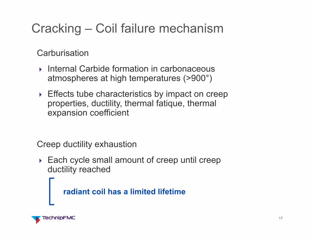
Cracking – Coil failure mechanism
Carburisation
Internal Carbide formation in carbonaceous atmospheres at high temperatures (>900°)
Effects tube characteristics by impact on creep properties, ductility, thermal fatique, thermal expansion coefficient
Creep ductility exhaustion
Each cycle small amount of creep until creep ductility reached
radiant coil has a limited lifetime

18
Cracking Furnace layout
Cracked Gas to separation section
FPH
ECO
HTC-1
HPSSH-1
HPSSH-2
HTC-2
Hydrocarbon Feed
Dilution Steam
Fuel Gas
Boiler Feed Water
VHP Steam
Steam Drum
Radiant Section
- Cracking reactions
- combustion
Convection Section
- Heat recovery
ID Fan
TransferLine Exchanger
Radiant CoilBurner
BFW
115 bara, 515°C
119 bara, 324°C
140°C
60°C
620°C
850°C
350°C
1250°C
120°C
Flue Gas to stack
Desuperheater
Radiant efficiency: 40-42%Overall efficiency: 93-95%

19
Cracking Furnace layout
Radiant box- radiant coils
TransferLine exchanger
Steam DrumFluegas ID Fan
Quench Oil Fitting
Radiant wall burners
Bottom burners
Convection Section
20
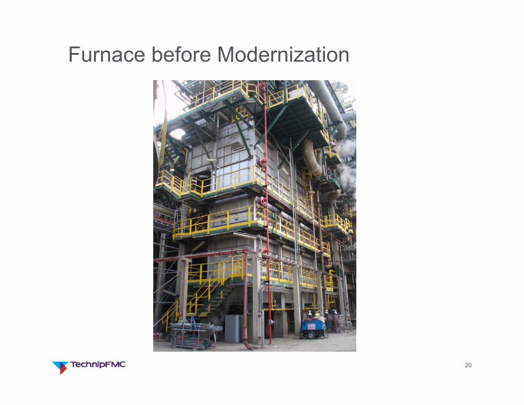
Furnace before Modernization

21
New Radiant Coil in Transport
22
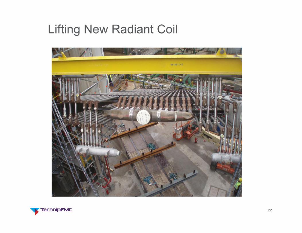
Lifting New Radiant Coil
23
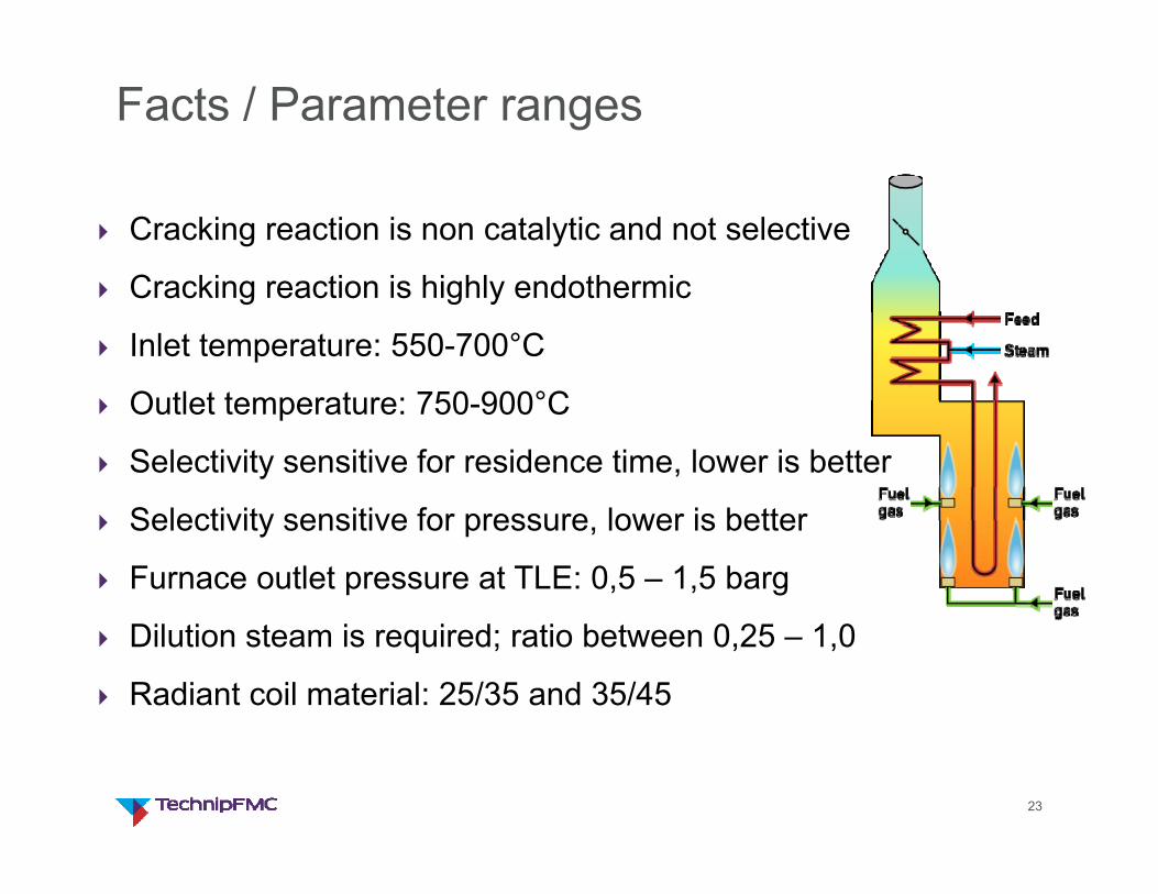
Facts / Parameter ranges
Cracking reaction is non catalytic and not selective
Cracking reaction is highly endothermic
Inlet temperature: 550-700°C
Outlet temperature: 750-900°C
Selectivity sensitive for residence time, lower is better
Selectivity sensitive for pressure, lower is better
Furnace outlet pressure at TLE: 0,5 – 1,5 barg
Dilution steam is required; ratio between 0,25 – 1,0
Radiant coil material: 25/35 and 35/45

24
Facts / Limitations
Coking rate Coke layer increases TMT Coke layer increases pressure drop over radiant coil
Run length determined by: Maximum allowable TMT (Outlet tube) Coil pressure drop (critical flow venturi stays critical)
Run length, typically 40-75 days
Decoke with steam/air after EOR; 1-3 days duration
Operation modes: SOR, MOR, EOR, Hot standby to fractionator, Hot standby to decoke system, Decoke

25
The Magic of Cracking
Optimization of:
Coil selection
Coil sizing
against:
Yields
Runlength
Feedstock flexibility
Operating cost
Investment cost• SPYRO® steam cracking simulation
software is used by most cracking furnace operators

26
Radiant coil - metallurgy
Tube 1 2
Material 25Cr35NiNbMicro-alloy
35Cr45NiNbMicro-alloy
DT 1080 °C 1115 °C
DP100.000 hrs10.000 hrs
3.9 barg4.9 barg
3.5 barg4.6 barg
GK6 radiant coil - typical Two pass
Outlet tube highest temperatures
Highest process temperature
Coke formation
27
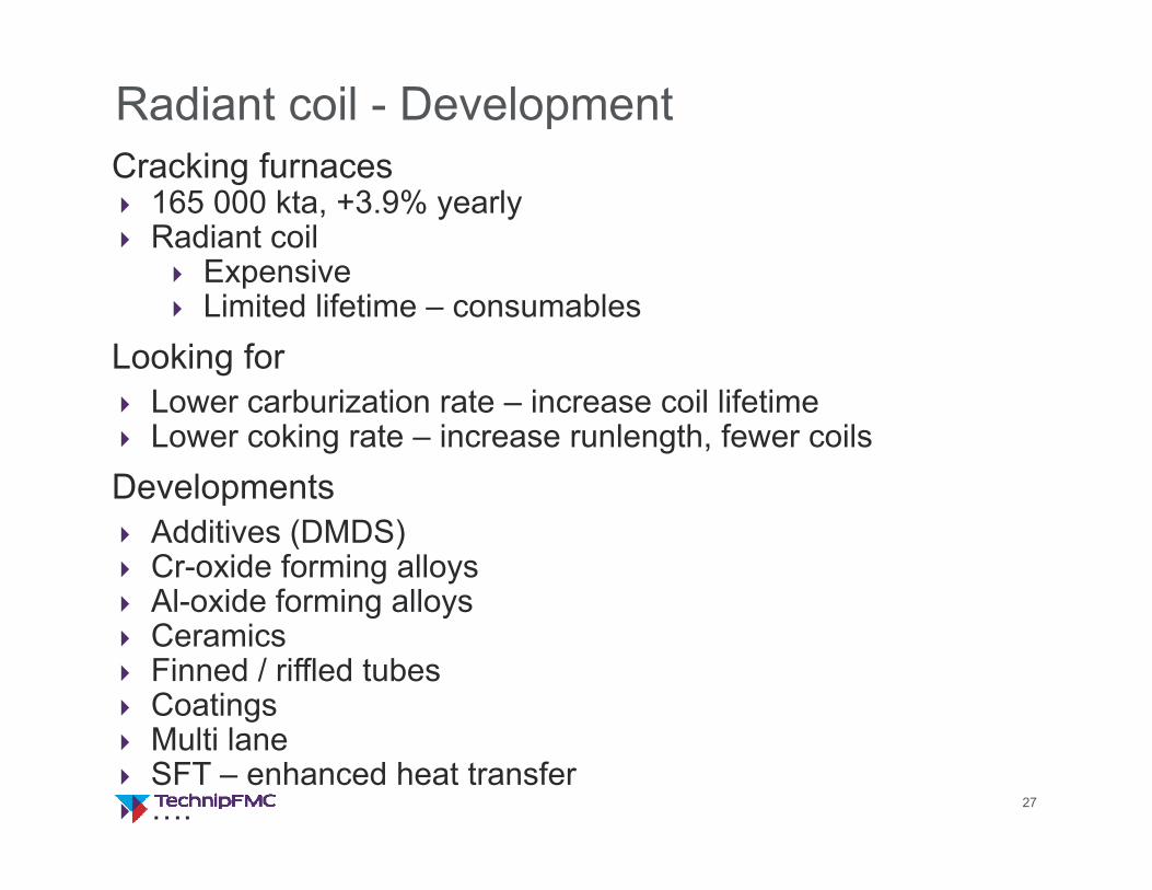
Radiant coil - DevelopmentCracking furnaces 165 000 kta, +3.9% yearly Radiant coil
Expensive Limited lifetime – consumables
Looking for Lower carburization rate – increase coil lifetime Lower coking rate – increase runlength, fewer coilsDevelopments Additives (DMDS) Cr-oxide forming alloys Al-oxide forming alloys Ceramics Finned / riffled tubes Coatings Multi lane SFT – enhanced heat transfer ….

2828
3. Latest Applied Technologies in Furnace DesignMulti lane radiant coilsSwirl Flow Tube®
Large Scale Vortex® Burner

33
Dual-lane GK6®
top view
80+ furnaces &
7,000+ KTA ethylene
produced with
Dual-lane GK6®
technology

34
Triple-lane GK6®
top view
Inlet tubes
Inlet tubes
Outlet tubes
Tube positions optimized:Outlet tubes to the center laneInlet tubes to the outside lanes

35
Triple-lane Features & Advantages
Inlet tubes at outside, facing burners & refractory Heat is shifted to inlet tubes
Outlet tubes at inside, away from direct radiant sourcesUniform circumferential radiation combined with large tube-tube spacing Reduced Peak to Average Heat-flux on outlet tube
Large tube-tube spacingSame amount of tubes in 3 lanes vs in 2 lanes
Overall ImpactImproved heat flux profile & decreased maximum TMTImproved performance

36
Biasing heat flux towards inlet tubes
Hea
tflu
x
Coil length
3-Lane 2-Lane
Lower flux to the outlet tubes
Higher flux to inlet tubes
Improved thermal utilization of radiant coil

37
Improved Circumferential Temperature Distribution Outlet Tubes
Triple-Lane →
Inlets peak at refractory side
Inlet gradient similar to dual-lane
Outlet tube circumferential heat distribution very uniform
Inter-lane side
Refractory side
← Dual-Lane All tubes peak at refractory side
All tubes dip at inter-lane side
InletOutlet
Refractory side
Inter-lane side
38
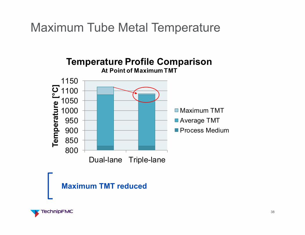
Maximum Tube Metal Temperature
800850900950
1000105011001150
Dual-lane Triple-lane
Tem
pera
ture
[°C
]Temperature Profile Comparison
At Point of Maximum TMT
Maximum TMTAverage TMTProcess Medium
Maximum TMT reduced

40
Triple-lane 1-1 “U” Coil:
top view perspective view
42
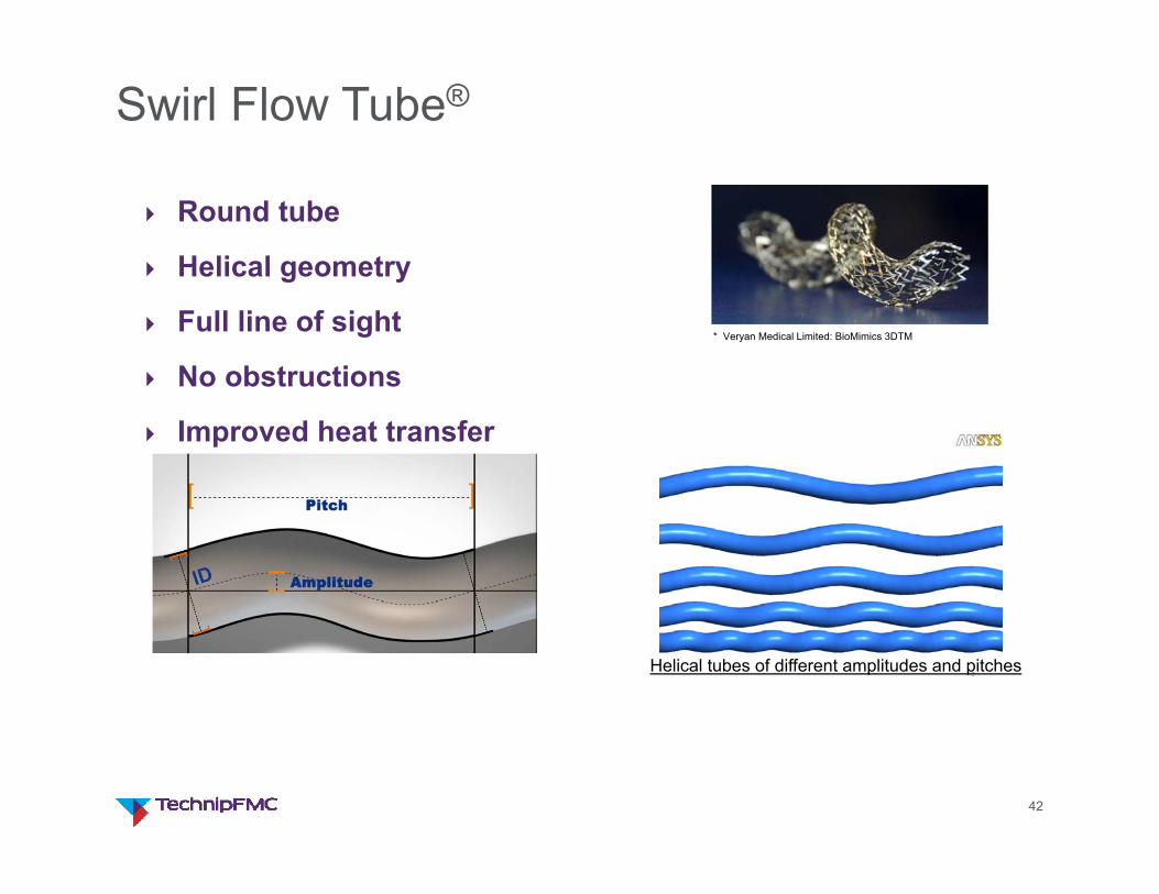
Swirl Flow Tube®
Round tube
Helical geometry
Full line of sight
No obstructions
Improved heat transfer
Helical tubes of different amplitudes and pitches
* Veryan Medical Limited: BioMimics 3DTM

43
Relative Coking Rates
Substantially lower coking rates observed due to
Lower wall temperature
Increased turbulence
Ethane Naphtha
Rel
ativ
e C
okin
g ra
te
StraightSFT®
Footnotes: (1) Data from Pilot Steam Cracker of Universiteit Gent

50
Requirements for Ultra Low NOx burners NOx emission in the range 50 … 100 mg/Nm3
Safety: Burner shall be stable for all operating conditions
Stable flame and no flame impingement
Uniform heat flux profile resulting in uniform tube wall temperatures
Optimized firebox efficiency
Burner shall be suitable for revamp and new furnace design
Ability to operate at a high firing intensity
Low maintenance costs
Sound pressure level <76 dB(A) @ 1 m.
The LSV burner meets these requirements

52
LSV ® burner overview
Simple robust design
Uses a combination of techniques to prevent NOx formation
Proven ultra low NOx performance
Designed to have optimized heat release profile for the most optimal furnace design
Suitable for furnace revamp and grass root furnace designs

53
Operational ExperienceLSV design data
Excess air % 7 – 15Flue Gas Temp (box temp) °C 1030-1360Combustion Air Temp °C Ambient-470NOx Emission @ 3 % O2 ppmv 25 – 50

54
Operational Experience
Excellent flame patterns and flame stability
Very good heat distribution on coils
High firebox efficiency
Low NOx emission
Proven design, trouble free operation
Reported low maintenance cost
Manufacturing by TechnipFMC
More than 1000 LSV burners have been applied

55
This document and all information herein are confidential, and may not be used, reproduced or distributed without prior authorization of TechnipFMC.


