44
NEW WASHER FROM MABE Revise June 21 O6-MAN-AW-02
| Date post: | 12-May-2018 |
| Category: |
Documents |
| Upload: | nguyentuyen |
| View: | 217 times |
| Download: | 2 times |
NEW WASHER FROM MABE
Revise June 21 O6-MAN-AW-02
2
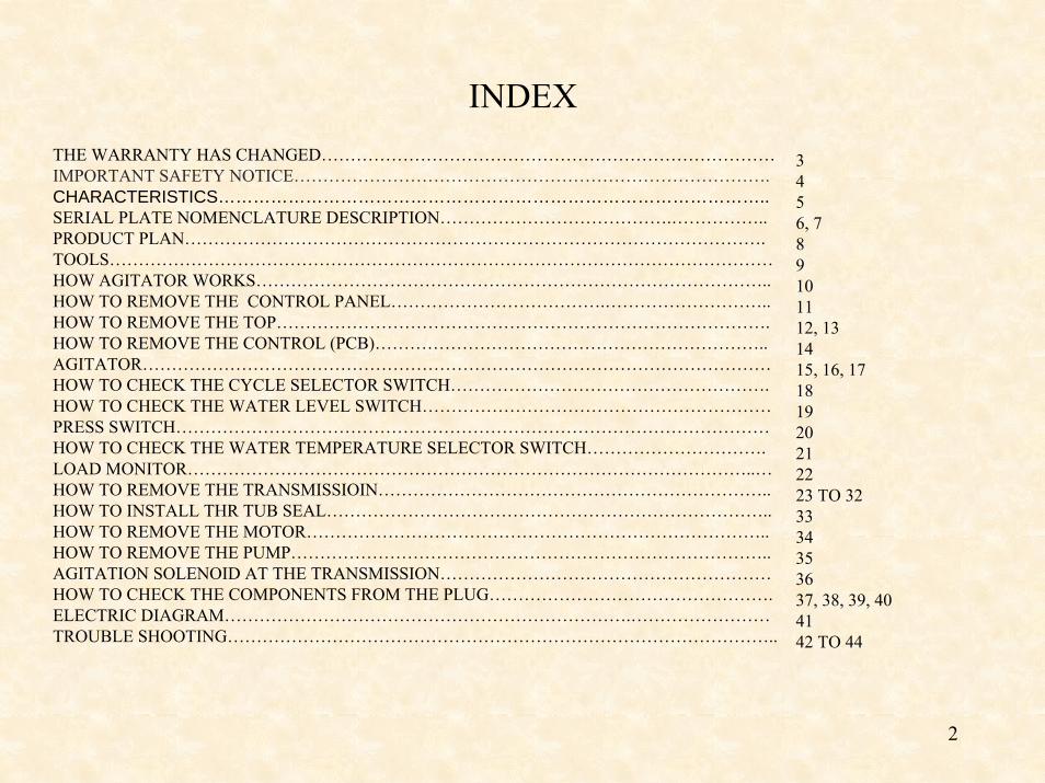
INDEXTHE WARRANTY HAS CHANGED……………………………………………………………………IMPORTANT SAFETY NOTICE……………………………………………………………………….CHARACTERISTICS…………………………………………………………………………………..SERIAL PLATE NOMENCLATURE DESCRIPTION………………………………….……………..PRODUCT PLAN……………………………………………………………………………………….TOOLS……………………………………………………………………………………………………HOW AGITATOR WORKS……………………………………………………………………………..HOW TO REMOVE THE CONTROL PANEL……………………………….………………………..HOW TO REMOVE THE TOP………………………………………………………………………….HOW TO REMOVE THE CONTROL (PCB)…………………………………………………………..AGITATOR………………………………………………………………………………………………HOW TO CHECK THE CYCLE SELECTOR SWITCH……………………………………………….HOW TO CHECK THE WATER LEVEL SWITCH……………………………………………………PRESS SWITCH…………………………………………………………………………………………HOW TO CHECK THE WATER TEMPERATURE SELECTOR SWITCH………………………….LOAD MONITOR……………………………………………………………………………………..…HOW TO REMOVE THE TRANSMISSIOIN…………………………………………………………..HOW TO INSTALL THR TUB SEAL………………………………………………………………….. HOW TO REMOVE THE MOTOR……………………………………………………………………..HOW TO REMOVE THE PUMP………………………………………………………………………..AGITATION SOLENOID AT THE TRANSMISSION…………………………………………………HOW TO CHECK THE COMPONENTS FROM THE PLUG………………………………………….ELECTRIC DIAGRAM…………………………………………………………….……………………TROUBLE SHOOTING…………………………………………………………………………………..
3456, 789101112, 131415, 16, 17181920212223 TO 323334353637, 38, 39, 404142 TO 44
3
THE WARRANTY HAS CHANGED
Very Important: Starting Jan 1st 2006 production code AL, The warranty has changed to one year on parts & labor.
You will have to pay attention to serial numbers. Any appliance manufactured prior to AL will have the previous warranty and any appliance manufactures after AL will have a one year warranty on parts and labor.

4
IMPORTANT SAFETY NOTICE Warning: This information is intended for use by individuals possessing adequate backgrounds of electrical, electronic and mechanical experience.
Any attempt to repair a major appliance may result in personal injury and property damage. The manufacturer or seller cannot be responsible for the interpretation of this information, nor can it assume any liability in connection with its use.
CAUTIONTo avoid personal injury while servicing this unit, disconnect power before servicing. If grounding wires, screws, straps, clips, nuts, or washers used to complete a path to ground are removed for service, they must be returned to their original position and properly fastened.
mabe CONFIDENTIAL AND PROPRIETARY INFORMATION-NOT FOR PUBLIC DISCLOSURE. May 2006

5
EASY BRAND PRODUCT CHARACTERISTICS
PRODUCT FEATURES:
CAPACITY
2 sizes available:
24” width (2.5 cu. ft. capacity)
27” width (2.5 and 3.2 cu. ft. capacity)
Electronic controls, 4 to 6 wash cycles, bleach dispenser & fabric softener dispenser. *Fabric softener dispenser only available on some 27” models.
ENERGY / WATER
Efficiency (MEF: Modified Energy Factor) 1.04 minimum; 2004 compliant
Water Usage (WF: Water Factor) 43 + - 1 gallon
CONTROL
Location Rear
Control Type / Layout Electronic
GENERAL APPEARANCE, Unit Colors White
Plastic Basket
GENERAL FEATURES
Agitator
Leveling System
Bleach Dispenser
Basket Access Diameter, 15.148 inches
Wash Temperatures: “Hot” : 43 °C +- 2°C ; “Warm” 26°C +- 2°C ; “Cold”: Supply water temperature
Rinse Temperatures: Supply water temperature
Water Levels: 3
WASH CYCLES
Total number: 4 to 6 wash cycles.
ELECTRICAL REQUIREMENTS
Voltage: 120 volt
Current: 12 amp maximum 60 Hz
6
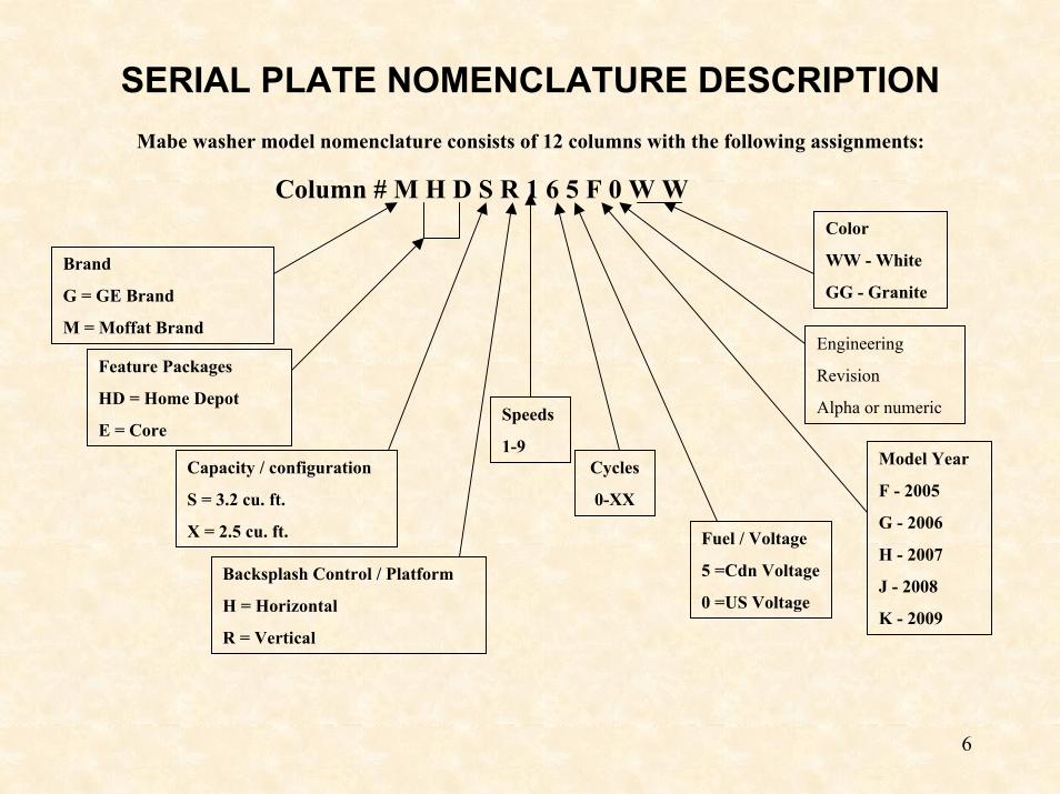
SERIAL PLATE NOMENCLATURE DESCRIPTIONMabe washer model nomenclature consists of 12 columns with the following assignments:
Color
WW - White
GG - Granite
Column # M H D S R 1 6 5 F 0 W W
Brand
G = GE Brand
M = Moffat Brand
Feature Packages
HD = Home Depot
E = Core
Capacity / configuration
S = 3.2 cu. ft.
X = 2.5 cu. ft.
Backsplash Control / Platform
H = Horizontal
R = Vertical
Speeds
1-9Cycles
0-XX
Fuel / Voltage
5 =Cdn Voltage
0 =US Voltage
Model Year
F - 2005
G - 2006
H - 2007
J - 2008
K - 2009
Engineering
Revision
Alpha or numeric
7
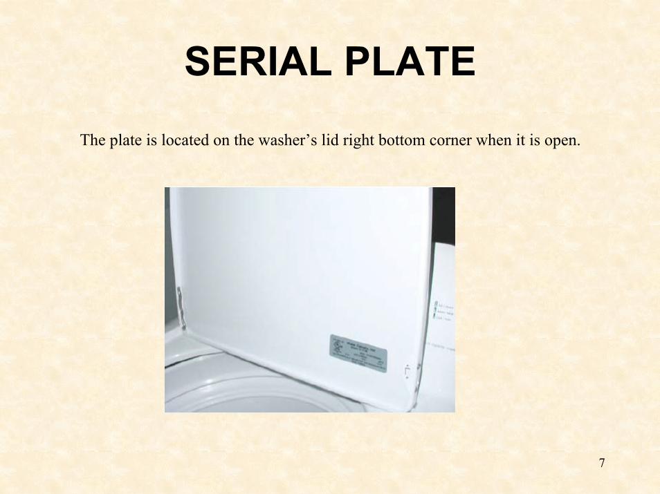
SERIAL PLATEThe plate is located on the washer’s lid right bottom corner when it is open.
8
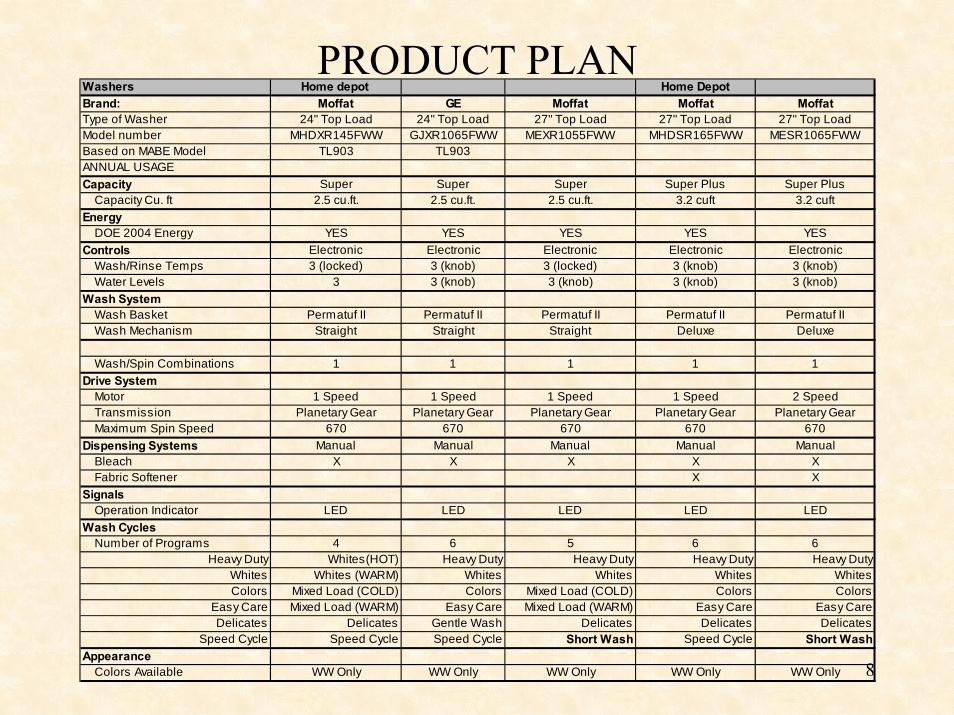
Washers Home depot Home DepotBrand: Moffat GE Moffat Moffat MoffatType of Washer 24" Top Load 24" Top Load 27" Top Load 27" Top Load 27" Top LoadModel number MHDXR145FWW GJXR1065FWW MEXR1055FWW MHDSR165FWW MESR1065FWWBased on MABE Model TL903 TL903ANNUAL USAGECapacity Super Super Super Super Plus Super Plus Capacity Cu. ft 2.5 cu.ft. 2.5 cu.ft. 2.5 cu.ft. 3.2 cuft 3.2 cuftEnergy DOE 2004 Energy YES YES YES YES YESControls Electronic Electronic Electronic Electronic Electronic Wash/Rinse Temps 3 (locked) 3 (knob) 3 (locked) 3 (knob) 3 (knob) Water Levels 3 3 (knob) 3 (knob) 3 (knob) 3 (knob)Wash System Wash Basket Permatuf II Permatuf II Permatuf II Permatuf II Permatuf II Wash Mechanism Straight Straight Straight Deluxe Deluxe
Wash/Spin Combinations 1 1 1 1 1Drive System Motor 1 Speed 1 Speed 1 Speed 1 Speed 2 Speed Transmission Planetary Gear Planetary Gear Planetary Gear Planetary Gear Planetary Gear Maximum Spin Speed 670 670 670 670 670Dispensing Systems Manual Manual Manual Manual Manual Bleach X X X X X Fabric Softener X XSignals Operation Indicator LED LED LED LED LEDWash Cycles Number of Programs 4 6 5 6 6
Heavy Duty Whites(HOT) Heavy Duty Heavy Duty Heavy Duty Heavy DutyWhites Whites (WARM) Whites Whites Whites WhitesColors Mixed Load (COLD) Colors Mixed Load (COLD) Colors Colors
Easy Care Mixed Load (WARM) Easy Care Mixed Load (WARM) Easy Care Easy CareDelicates Delicates Gentle Wash Delicates Delicates Delicates
Speed Cycle Speed Cycle Speed Cycle Short Wash Speed Cycle Short WashAppearance Colors Available WW Only WW Only WW Only WW Only WW Only
PRODUCT PLAN
9
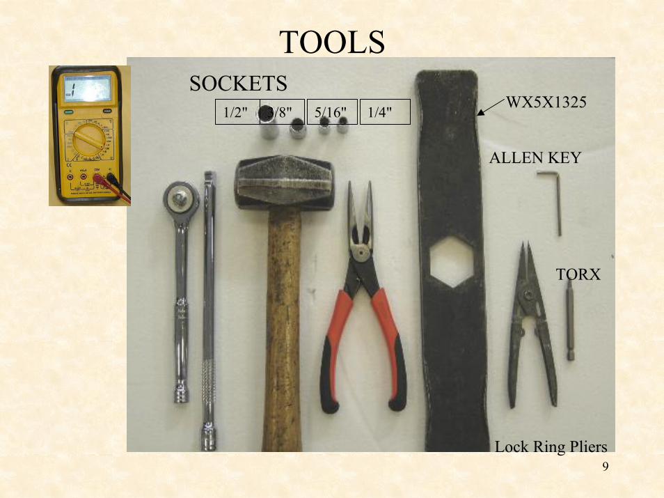
TOOLS
1/4"5/16"3/8"1/2"
SOCKETS
ALLEN KEY
TORX
WX5X1325
Lock Ring Pliers
10
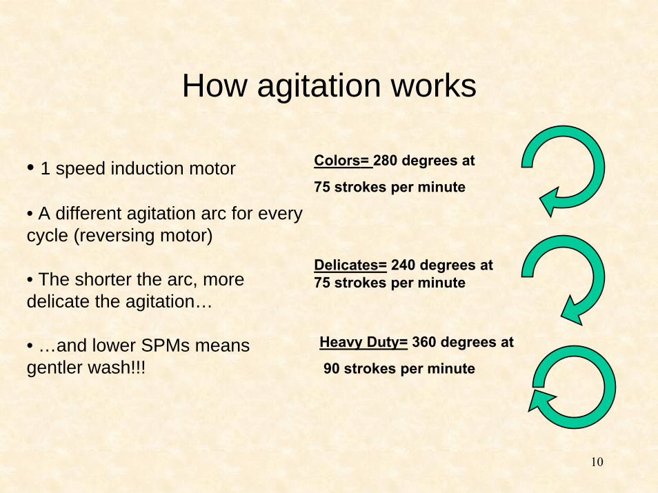
How agitation works
Colors= 280 degrees at
75 strokes per minute• 1 speed induction motor
• A different agitation arc for every cycle (reversing motor)
• The shorter the arc, more delicate the agitation…
• …and lower SPMs means gentler wash!!!
Delicates= 240 degrees at 75 strokes per minute
Heavy Duty= 360 degrees at
90 strokes per minute
11
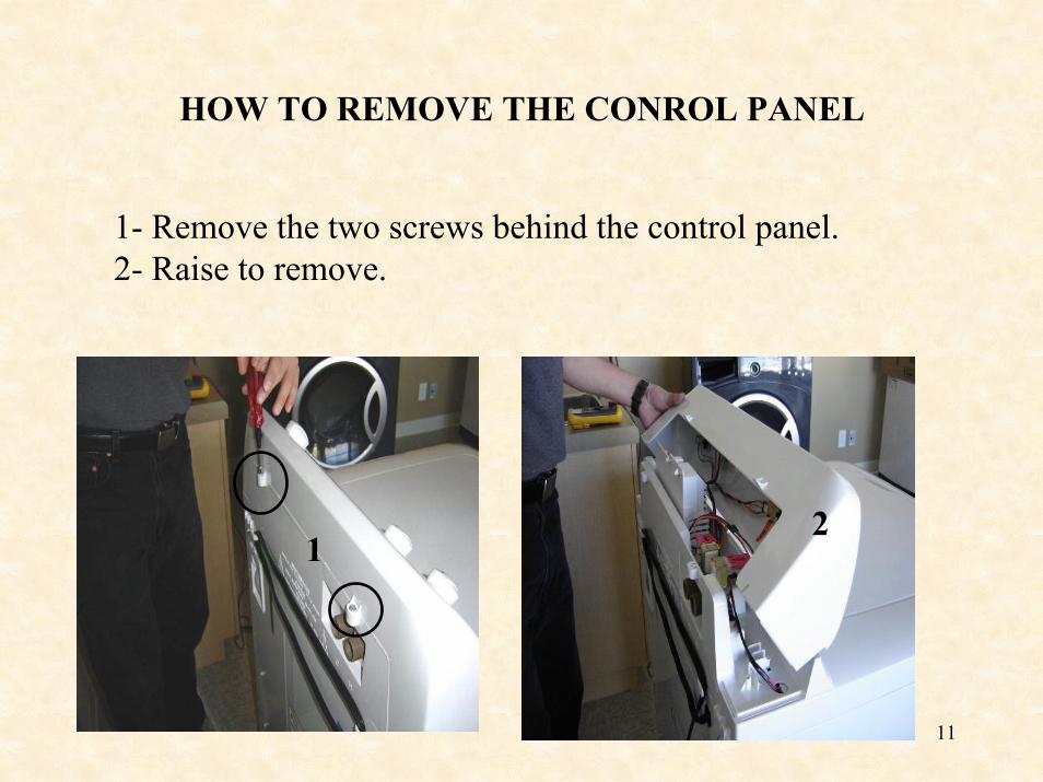
HOW TO REMOVE THE CONROL PANEL
1- Remove the two screws behind the control panel.2- Raise to remove.
12
12
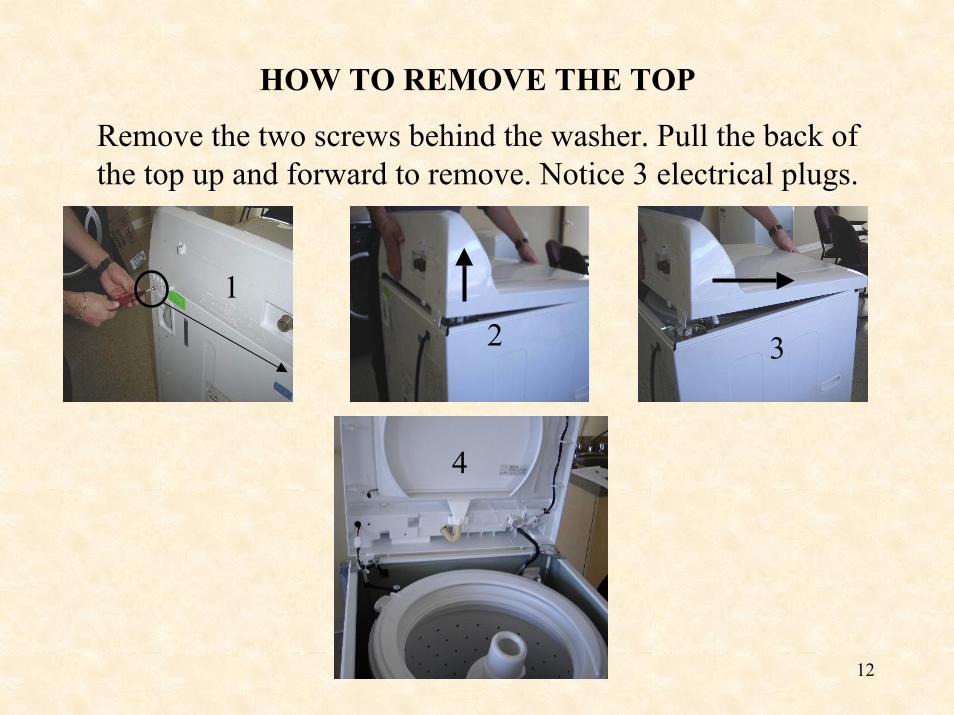
HOW TO REMOVE THE TOP
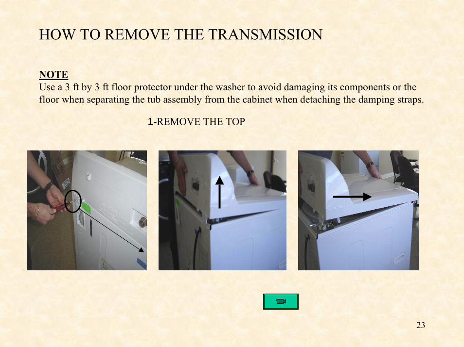
Remove the two screws behind the washer. Pull the back of the top up and forward to remove. Notice 3 electrical plugs.
3
12
4
13
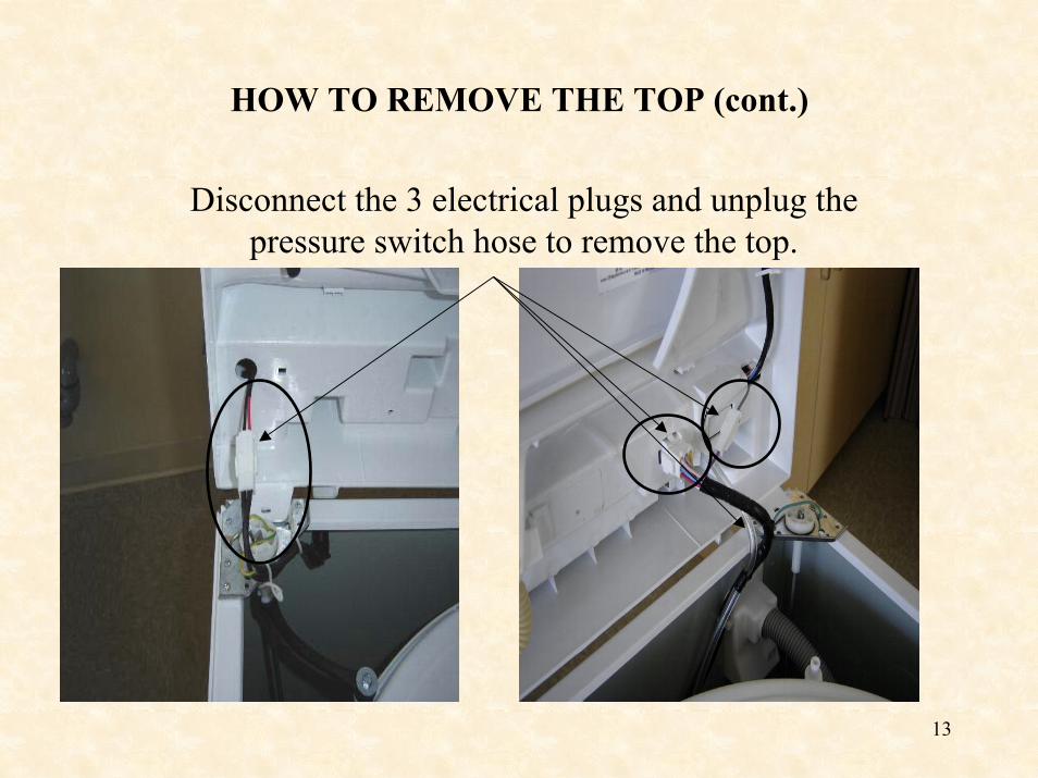
HOW TO REMOVE THE TOP (cont.)
Disconnect the 3 electrical plugs and unplug the pressure switch hose to remove the top.
14
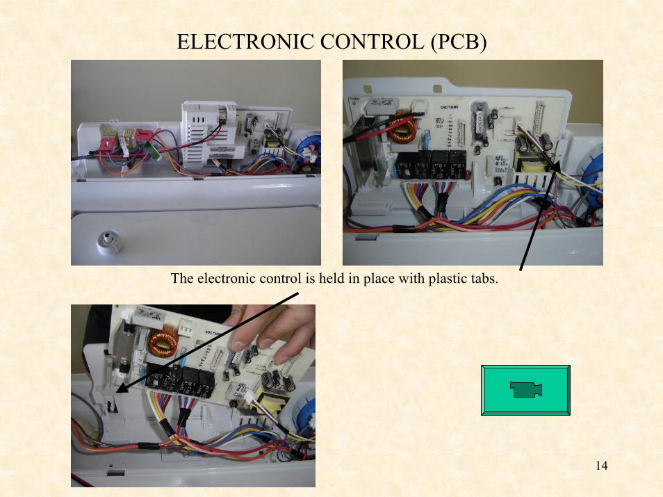
ELECTRONIC CONTROL (PCB)
The electronic control is held in place with plastic tabs.
15
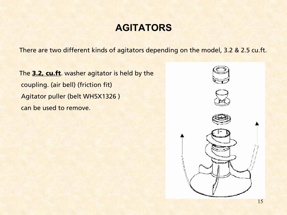
AGITATORS
There are two different kinds of agitators depending on the model, 3.2 & 2.5 cu.ft.
The 3.2, cu.ft. washer agitator is held by the
coupling. (air bell) (friction fit)
Agitator puller (belt WH5X1326 )
can be used to remove.
16
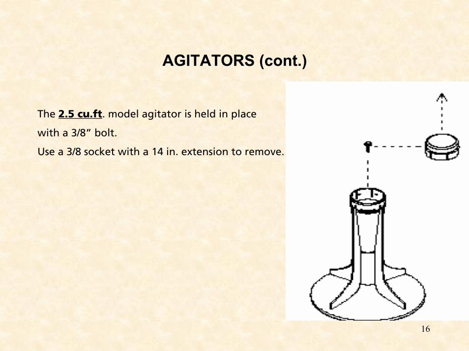
AGITATORS (cont.)
The 2.5 cu.ft. model agitator is held in place
with a 3/8” bolt.
Use a 3/8 socket with a 14 in. extension to remove.
17
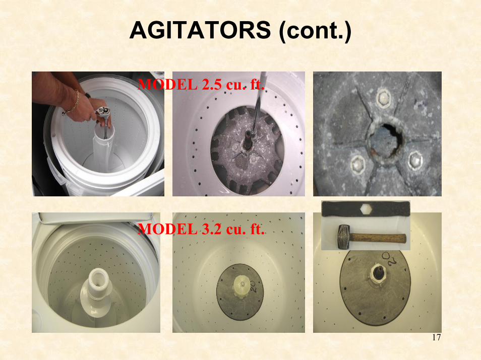
AGITATORS (cont.)
MODEL 2.5 cu. ft.
MODEL 3.2 cu. ft.
18
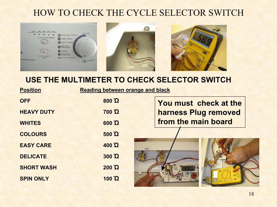
HOW TO CHECK THE CYCLE SELECTOR SWITCH
USE THE MULTIMETER TO CHECK SELECTOR SWITCHPosition Reading between orange and black
OFF 800 Ώ
HEAVY DUTY 700 Ώ
WHITES 600 Ώ
COLOURS 500 Ώ
EASY CARE 400 Ώ
DELICATE 300 Ώ
SHORT WASH 200 Ώ
SPIN ONLY 100 Ώ
You must check at the harness Plug removed from the main board
19
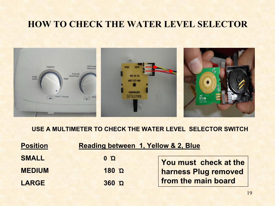
HOW TO CHECK THE WATER LEVEL SELECTOR
21
USE A MULTIMETER TO CHECK THE WATER LEVEL SELECTOR SWITCH
Position Reading between 1, Yellow & 2, Blue
SMALL 0 Ώ
MEDIUM 180 Ώ
LARGE 360 Ώ
You must check at the harness Plug removed from the main board
20
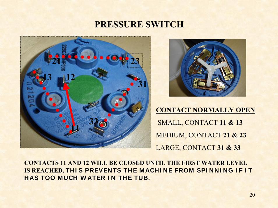
PRESSURE SWITCH
23
1133
21
3113 12
CONTACT NORMALLY OPEN
SMALL, CONTACT 11 & 13
MEDIUM, CONTACT 21 & 23
LARGE, CONTACT 31 & 33
CONTACTS 11 AND 12 WILL BE CLOSED UNTIL THE FIRST WATER LEVEL IS REACHED, THIS PREVENTS THE MACHINE FROM SPINNING IF IT HAS TOO MUCH WATER IN THE TUB.
21
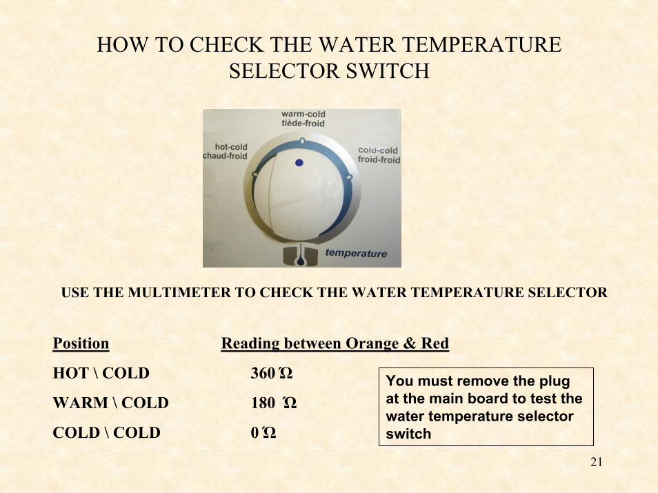
HOW TO CHECK THE WATER TEMPERATURE SELECTOR SWITCH
USE THE MULTIMETER TO CHECK THE WATER TEMPERATURE SELECTOR
Position Reading between Orange & Red
HOT \ COLD 360 Ώ
WARM \ COLD 180 Ώ
COLD \ COLD 0 Ώ
You must remove the plug at the main board to test the water temperature selector switch
22
LOAD MONITOR
Speed sensor on motor « senses » difficult conditions (increased work load).
Ex: large load of clothes with not enough water.
Control board adjusts agitation arc to lessen burden on motor & transmission and reduce wear on clothes.
Ex: Arc goes from 280 degrees to 240 degrees, and reduces number of strokes per minute.
If load is lessened, control board re-sets to original setting.
Ex: Arc goes back up to 280 degree.
23
HOW TO REMOVE THE TRANSMISSION
NOTEUse a 3 ft by 3 ft floor protector under the washer to avoid damaging its components or the floor when separating the tub assembly from the cabinet when detaching the damping straps.
1-REMOVE THE TOP
24
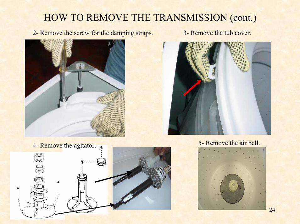
HOW TO REMOVE THE TRANSMISSION (cont.)2- Remove the screw for the damping straps. 3- Remove the tub cover.
5- Remove the air bell..
4- Remove the agitator.
25
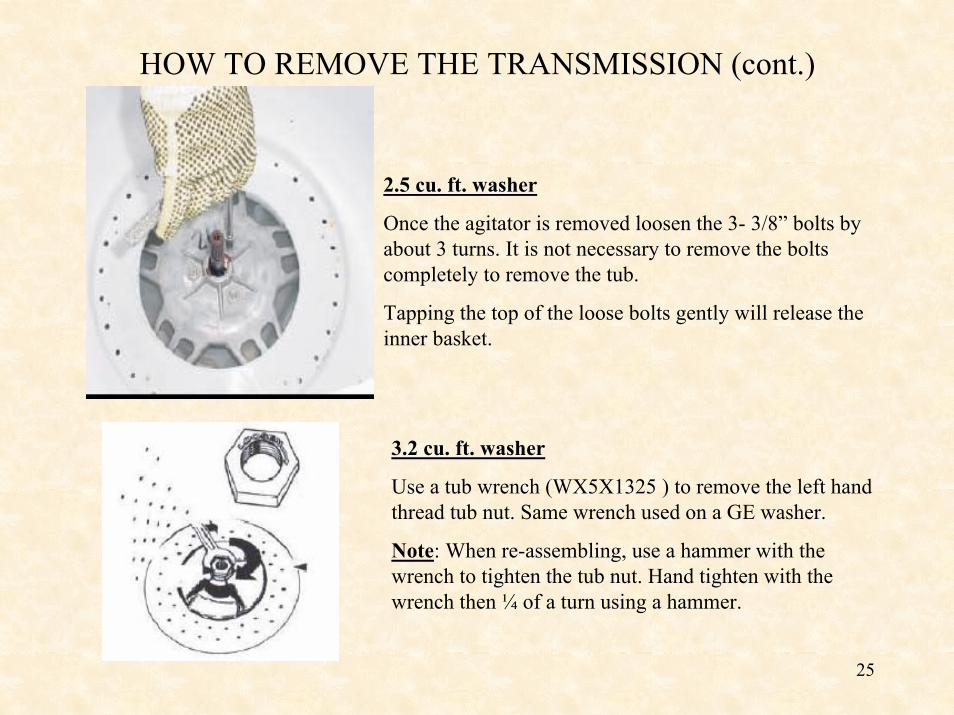
HOW TO REMOVE THE TRANSMISSION (cont.)
2.5 cu. ft. washer
Once the agitator is removed loosen the 3- 3/8” bolts by about 3 turns. It is not necessary to remove the bolts completely to remove the tub.
Tapping the top of the loose bolts gently will release the inner basket.
3.2 cu. ft. washer
Use a tub wrench (WX5X1325 ) to remove the left hand thread tub nut. Same wrench used on a GE washer.
Note: When re-assembling, use a hammer with the wrench to tighten the tub nut. Hand tighten with the wrench then ¼ of a turn using a hammer.
26
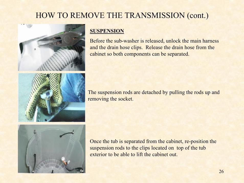
HOW TO REMOVE THE TRANSMISSION (cont.)
SUSPENSION
Before the sub-washer is released, unlock the main harness and the drain hose clips. Release the drain hose from the cabinet so both components can be separated.
The suspension rods are detached by pulling the rods up and removing the socket.
Once the tub is separated from the cabinet, re-position the suspension rods to the clips located on top of the tub exterior to be able to lift the cabinet out.
27
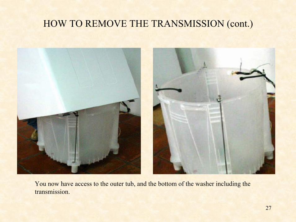
HOW TO REMOVE THE TRANSMISSION (cont.)
You now have access to the outer tub, and the bottom of the washer including the transmission.
28
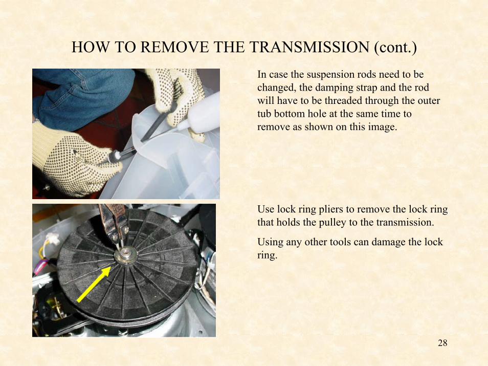
HOW TO REMOVE THE TRANSMISSION (cont.)In case the suspension rods need to be changed, the damping strap and the rod will have to be threaded through the outer tub bottom hole at the same time to remove as shown on this image.
Use lock ring pliers to remove the lock ring that holds the pulley to the transmission.
Using any other tools can damage the lock ring.
29
HOW TO REMOVE THE TRANSMISSION (cont.)
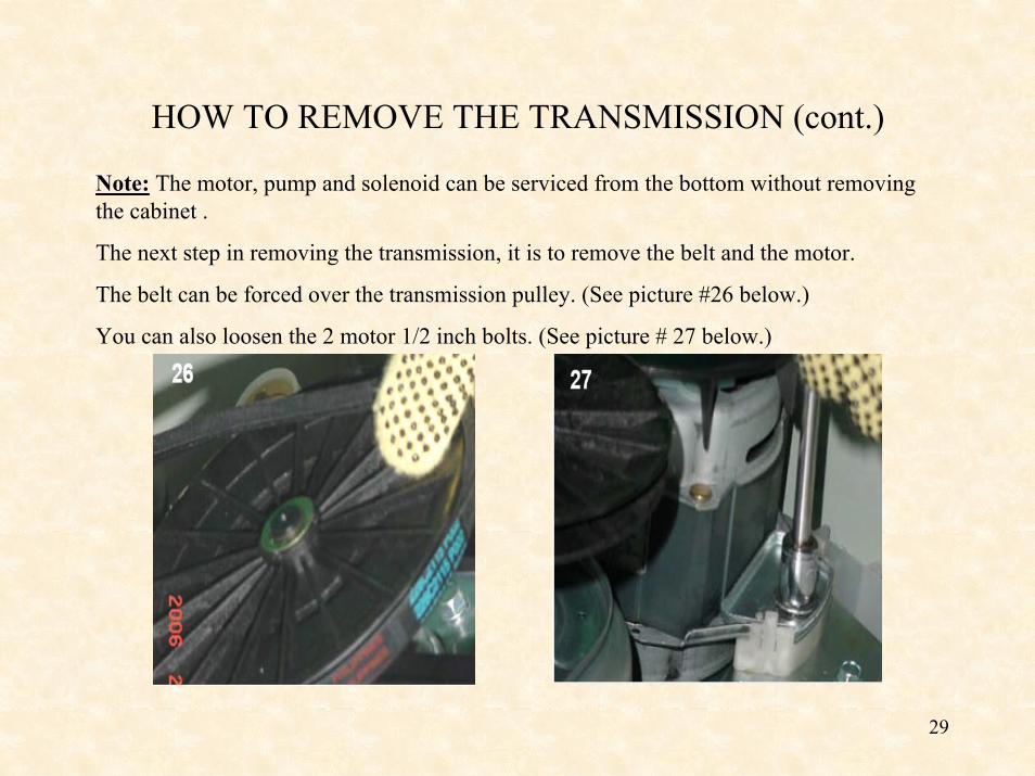
Note: The motor, pump and solenoid can be serviced from the bottom without removing the cabinet .
The next step in removing the transmission, it is to remove the belt and the motor.
The belt can be forced over the transmission pulley. (See picture #26 below.)
You can also loosen the 2 motor 1/2 inch bolts. (See picture # 27 below.)
30
HOW TO REMOVE THE TRANSMISSION (cont.)
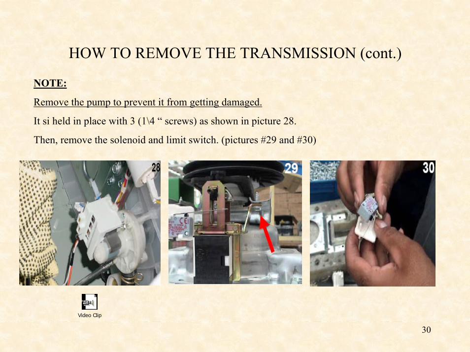
NOTE:
Remove the pump to prevent it from getting damaged.
It si held in place with 3 (1\4 “ screws) as shown in picture 28.
Then, remove the solenoid and limit switch. (pictures #29 and #30)
Video Clip
31
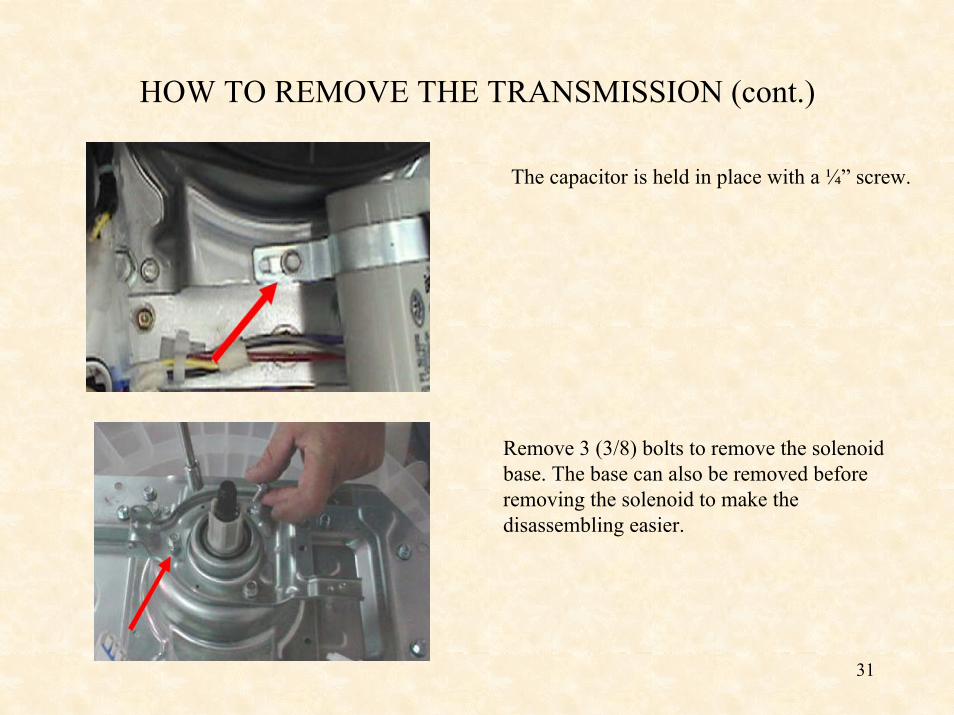
HOW TO REMOVE THE TRANSMISSION (cont.)
The capacitor is held in place with a ¼” screw.
Remove 3 (3/8) bolts to remove the solenoid base. The base can also be removed before removing the solenoid to make the disassembling easier.
32
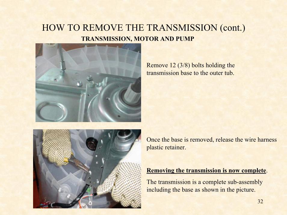
HOW TO REMOVE THE TRANSMISSION (cont.)TRANSMISSION, MOTOR AND PUMP
Remove 12 (3/8) bolts holding the transmission base to the outer tub.
Once the base is removed, release the wire harness plastic retainer.
Removing the transmission is now complete.
The transmission is a complete sub-assembly including the base as shown in the picture.

33
HOW TO INSTALL THE TUB SEALA new tub seal should always be changed when changing the transmission.
The seal must first be inserted on the transmission shaft taking the necessary care not to damage the internal part of the seal. This can be done by placing a plastic bag on the transmission assembly. When assembling the transmission with the base located in the bottom of the tub, the pressure must be made uniformly.
34
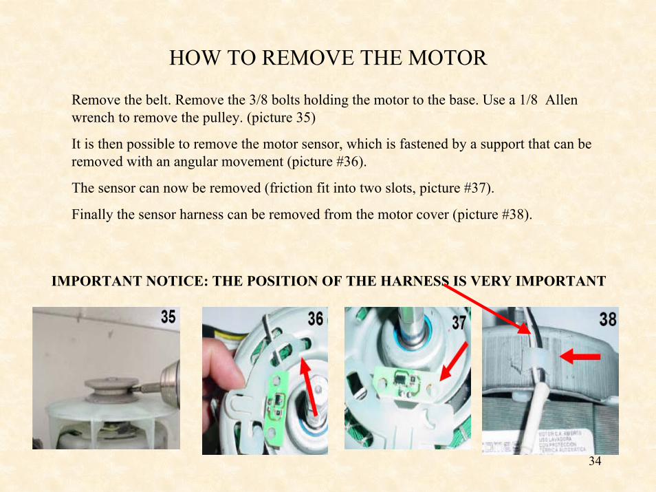
HOW TO REMOVE THE MOTOR
Remove the belt. Remove the 3/8 bolts holding the motor to the base. Use a 1/8 Allen wrench to remove the pulley. (picture 35)
It is then possible to remove the motor sensor, which is fastened by a support that can be removed with an angular movement (picture #36).
The sensor can now be removed (friction fit into two slots, picture #37).
Finally the sensor harness can be removed from the motor cover (picture #38).
IMPORTANT NOTICE: THE POSITION OF THE HARNESS IS VERY IMPORTANT
35
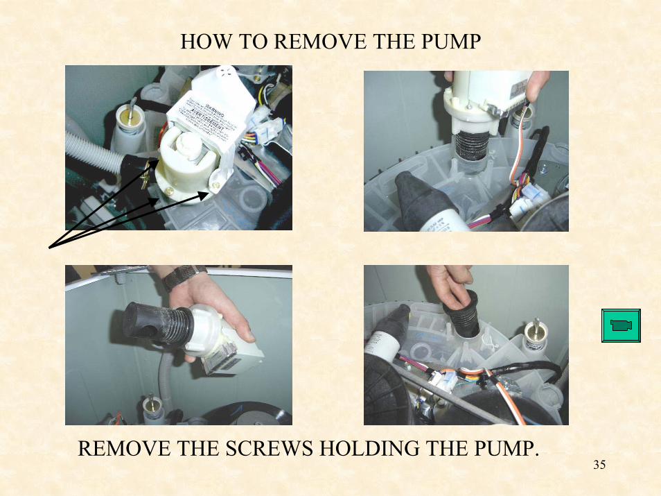
HOW TO REMOVE THE PUMP
REMOVE THE SCREWS HOLDING THE PUMP.
36
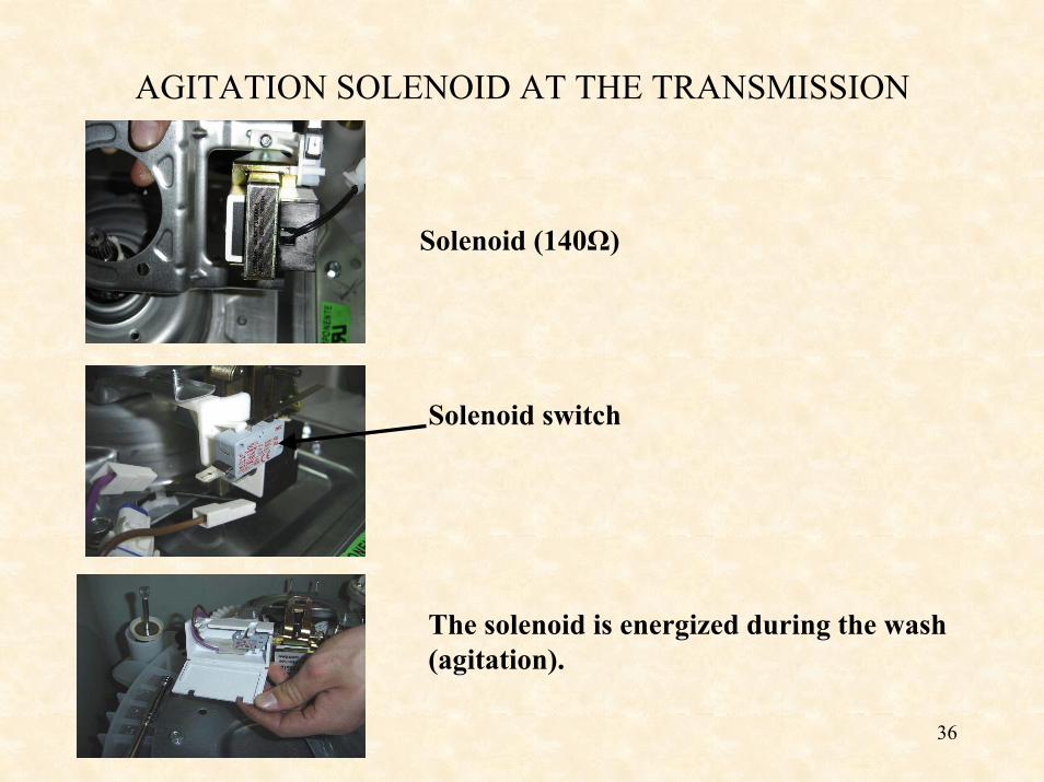
AGITATION SOLENOID AT THE TRANSMISSION
Solenoid (140Ω)
Solenoid switch
The solenoid is energized during the wash (agitation).
37
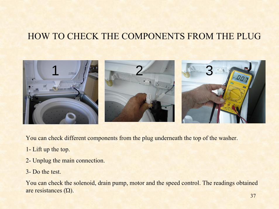
HOW TO CHECK THE COMPONENTS FROM THE PLUG
1 2 3
You can check different components from the plug underneath the top of the washer.
1- Lift up the top.
2- Unplug the main connection.
3- Do the test.
You can check the solenoid, drain pump, motor and the speed control. The readings obtained are resistances (Ώ).
38
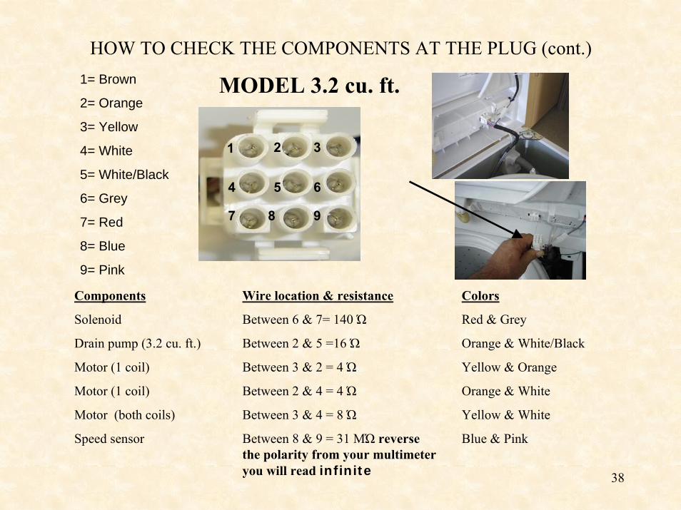
HOW TO CHECK THE COMPONENTS AT THE PLUG (cont.)
MODEL 3.2 cu. ft.1= Brown
2= Orange
3= Yellow
4= White
5= White/Black
6= Grey
7= Red
8= Blue
9= Pink
1 2 3
4 5 6
7 8 9
Components
Solenoid
Drain pump (3.2 cu. ft.)
Motor (1 coil)
Motor (1 coil)
Motor (both coils)
Speed sensor
Wire location & resistance
Between 6 & 7= 140 Ώ
Between 2 & 5 =16 Ώ
Between 3 & 2 = 4 Ώ
Between 2 & 4 = 4 Ώ
Between 3 & 4 = 8 Ώ
Between 8 & 9 = 31 MΏ reverse the polarity from your multimeteryou will read infinite
Colors
Red & Grey
Orange & White/Black
Yellow & Orange
Orange & White
Yellow & White
Blue & Pink
39
1 2 3
4 5 6
7 8 9
1 2 3
4 5 6
7 8 9
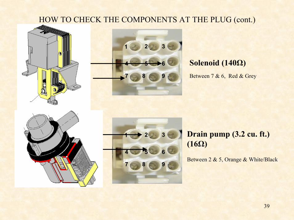
Solenoid (140Ω)Between 7 & 6, Red & Grey
Between 2 & 5, Orange & White/Black
Drain pump (3.2 cu. ft.)(16Ω)
HOW TO CHECK THE COMPONENTS AT THE PLUG (cont.)
40
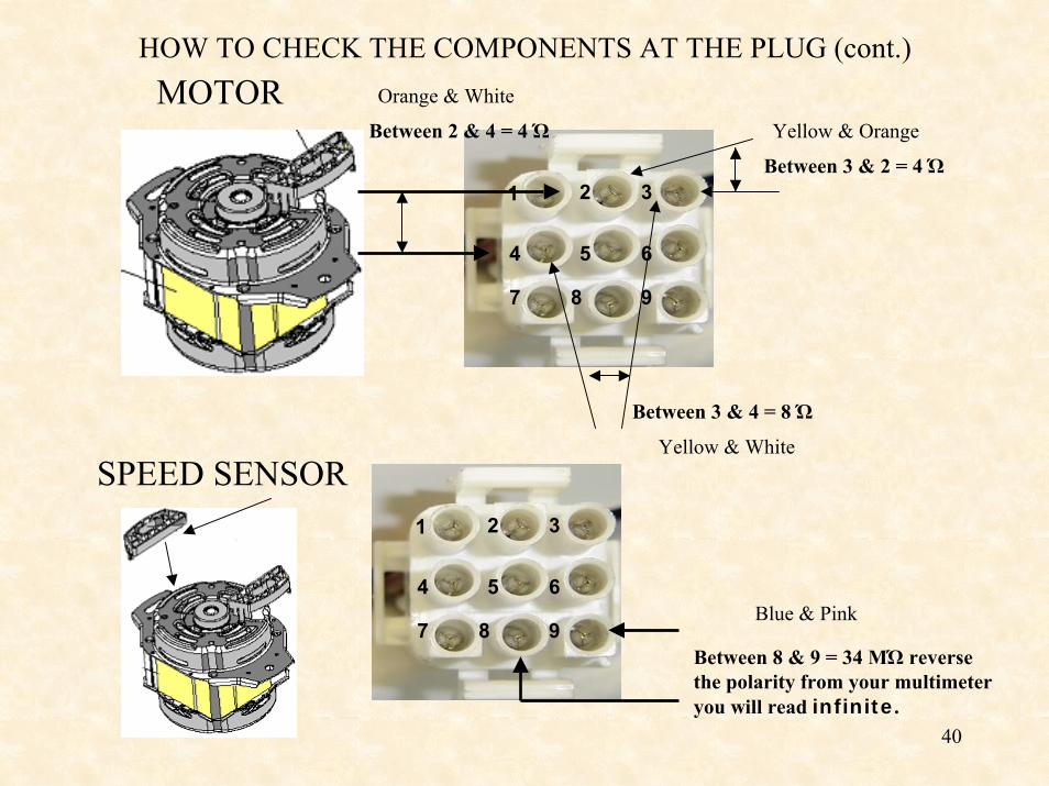
HOW TO CHECK THE COMPONENTS AT THE PLUG (cont.)MOTOR
1 2 3
4 5 6
7 8 9
Between 3 & 2 = 4 Ώ
Between 2 & 4 = 4 Ώ
Between 3 & 4 = 8 Ώ
1 2 3
4 5 6
7 8 9Between 8 & 9 = 34 MΏ reverse the polarity from your multimeter you will read infinite.
Orange & White
Yellow & Orange
Yellow & White
Blue & Pink
SPEED SENSOR
41
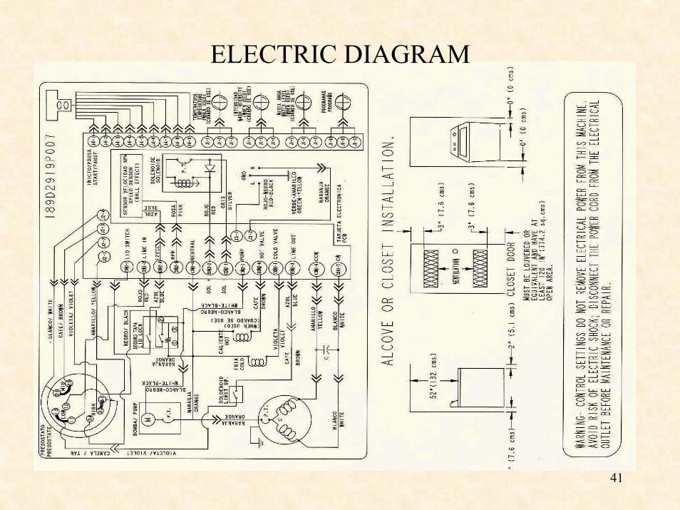
ELECTRIC DIAGRAM
42
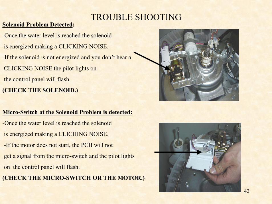
TROUBLE SHOOTINGSolenoid Problem Detected:
-Once the water level is reached the solenoid
is energized making a CLICKING NOISE.
-If the solenoid is not energized and you don’t hear a
CLICKING NOISE the pilot lights on
the control panel will flash.
(CHECK THE SOLENOID.)
Micro-Switch at the Solenoid Problem is detected:
-Once the water level is reached the solenoid
is energized making a CLICHING NOISE.
-If the motor does not start, the PCB will not
get a signal from the micro-switch and the pilot lights
on the control panel will flash.
(CHECK THE MICRO-SWITCH OR THE MOTOR.)
43
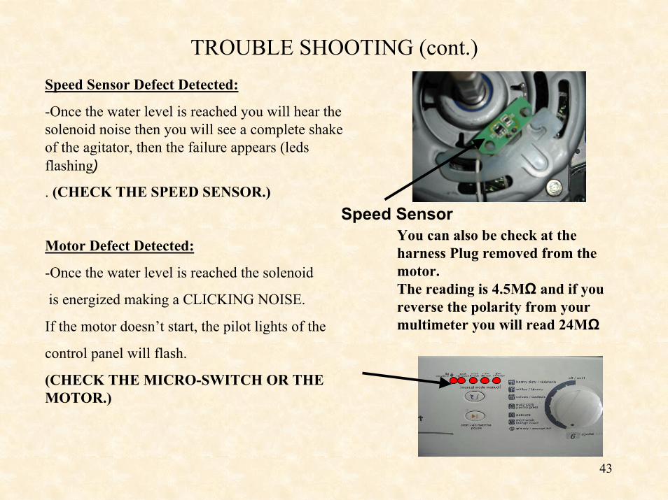
TROUBLE SHOOTING (cont.)Speed Sensor Defect Detected:
-Once the water level is reached you will hear the solenoid noise then you will see a complete shake of the agitator, then the failure appears (ledsflashing)
. (CHECK THE SPEED SENSOR.)
Motor Defect Detected:
-Once the water level is reached the solenoid
is energized making a CLICKING NOISE.
If the motor doesn’t start, the pilot lights of the
control panel will flash.
(CHECK THE MICRO-SWITCH OR THE MOTOR.)
Speed SensorYou can also be check at the harness Plug removed from the motor.The reading is 4.5MΩ and if you reverse the polarity from your multimeter you will read 24MΩ
44
TROUBLE SHOOTING (cont.)
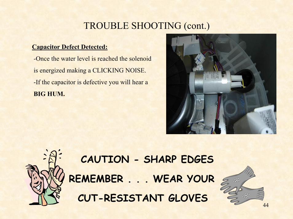
Capacitor Defect Detected:
-Once the water level is reached the solenoid
is energized making a CLICKING NOISE.
-If the capacitor is defective you will hear a
BIG HUM.
CAUTION - SHARP EDGES
REMEMBER . . . WEAR YOUR
CUT-RESISTANT GLOVES


