13
Newhurst ERF - Flue Gas Treatment
Newhurst ERF - Flue Gas Treatment

Flue Gas Treatment (FGT)
Newhurst ERF will incorporate state-of-the-art air pollution control technology to cool and clean the flue gas.
The process is a combination of Selective Non-Catalytic Reduction (SNCR) and Dry Flue Gas Cleaning.
This
2 Sources: Hitachi Zosen Inova
Boiler post-combustion chamber
Grate
Selective Non-Catalytic Reduction (SNCR)
3
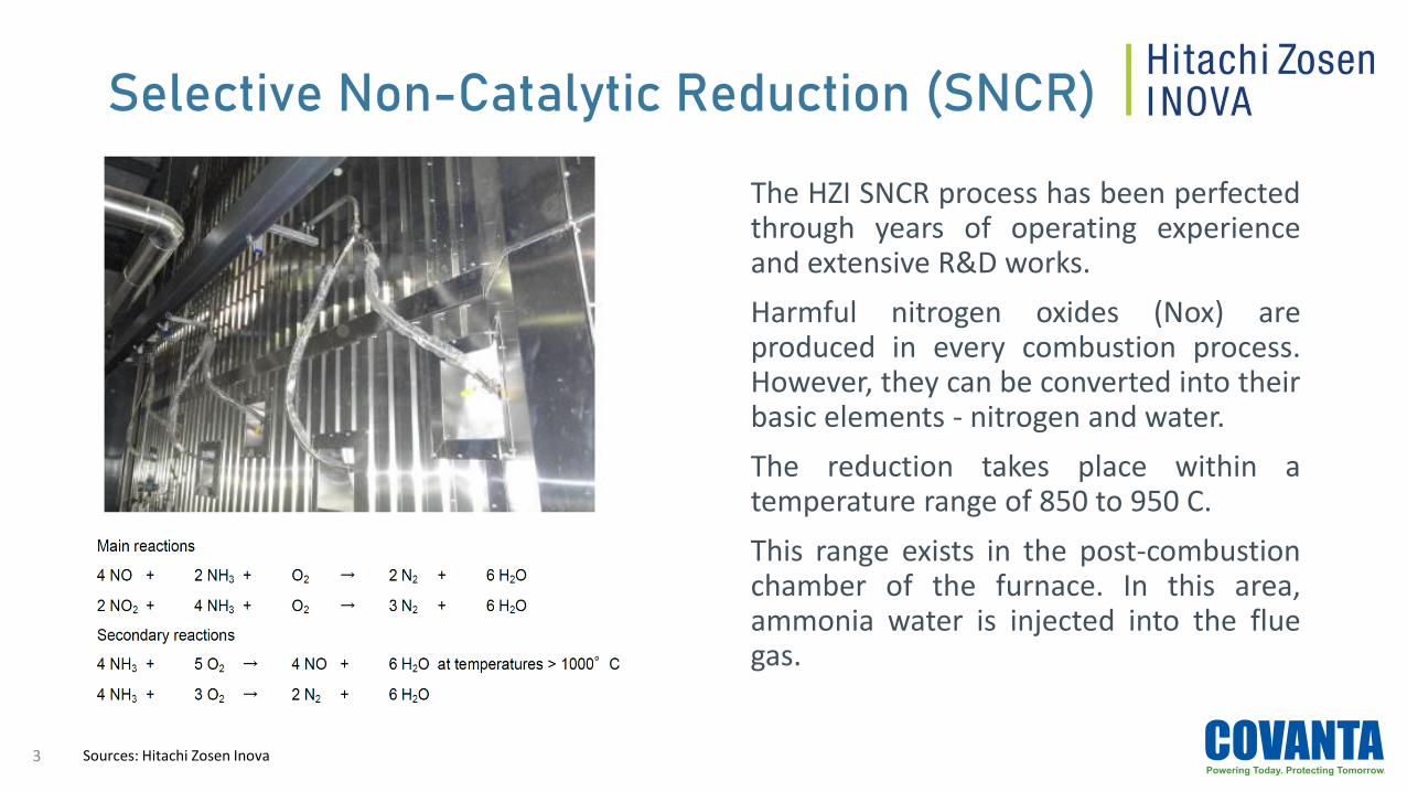
The HZI SNCR process has been perfectedthrough years of operating experienceand extensive R&D works.
Harmful nitrogen oxides (Nox) areproduced in every combustion process.However, they can be converted into theirbasic elements - nitrogen and water.
The reduction takes place within atemperature range of 850 to 950 C.
This range exists in the post-combustionchamber of the furnace. In this area,ammonia water is injected into the fluegas.
Sources: Hitachi Zosen Inova

Selective Non-Catalytic Reduction (SNCR)
4
• Located in the post-combustionchamber.
• Divided virtually into several verticalsegments.
• Each segment consist of:• Distribution module
• Injection nozzles on several levels
• The configuration of the nozzlesensures full-area coverage of theinjection medium across the entirecross section.
Sources: Hitachi Zosen Inova

Dry Flue Gas Cleaning Process
5
Purpose is to remove:• Dust particles
• Acidic gaseous contaminants by neutralization (hydrated lime)
• Organic pollutants, mercury and other heavy metals
Main Components of system• Reactor with additive injection
• Fabric filter for solid-gas separation
• Residue recirculation - to achieve the best adsorption performance with minimum additiveconsumption, solids from the fabric filter are recirculated into the reactor.

XEROSORP® Reactor
6 Sources: Hitachi Zosen Inova
Main components of the XEROSORP® process:
1. Plug flow type reactor with additive injection.
2. Fabric filter for solid-gas separation.
3. Mechanical system for residue recirculation.
4. Discharge of residues into the residue silo.
5. Screw conveyor to feed resides into the reactor.
6. Injection of additives (pneumatic conveying):
- Hydrated lime
- Powdered activated carbon

XEROSORP® Reactor
7
The dry flue gas treatment process isdesigned by HZI specialists to remove alldust particles, most of the acidic gaseouscontaminants by neutralisation withhydrated lime and organic pollutants aswell as mercury and other heavy metalsby adsorption on activated carbon.
The system consists of a reactor withadditive injection, fabric filter for solid-gas separation and residue recirculation.
To achieve the best adsorptionperformance with minimum additiveconsumption, solids from the fabric filterare recirculated into the reactor.
Sources: Hitachi Zosen Inova
Fabric Filter
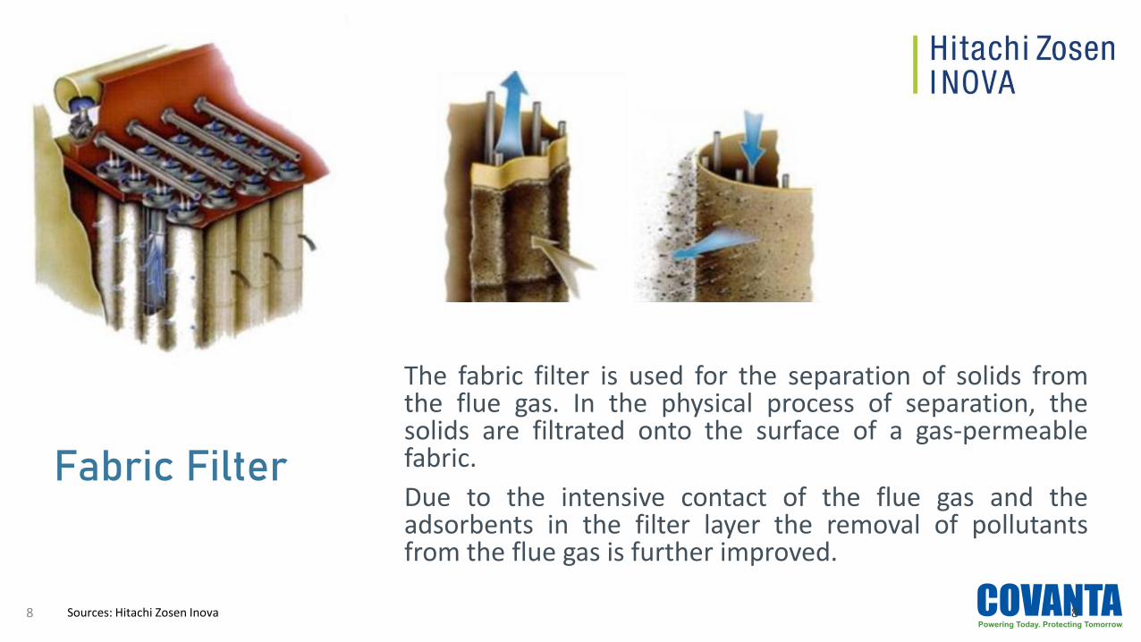
The fabric filter is used for the separation of solids fromthe flue gas. In the physical process of separation, thesolids are filtrated onto the surface of a gas-permeablefabric.
Due to the intensive contact of the flue gas and theadsorbents in the filter layer the removal of pollutantsfrom the flue gas is further improved.
8Sources: Hitachi Zosen Inova8
Residue Circulation
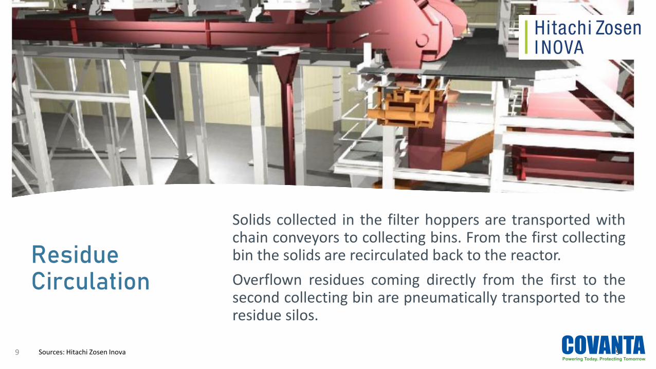
Solids collected in the filter hoppers are transported withchain conveyors to collecting bins. From the first collectingbin the solids are recirculated back to the reactor.
Overflown residues coming directly from the first to thesecond collecting bin are pneumatically transported to theresidue silos.
9Sources: Hitachi Zosen Inova9

Induced Draught Fan
The induced draught fan (ID fan) generates therequired negative pressure in the combustionchamber and is conducting the flue gas from thefurnace through the flue gas cleaning system tothe stack.
The ID fan rotation speed is regulated by thecombustion chamber pressure controller.
10 Sources: Hitachi Zosen Inova and Pollrich
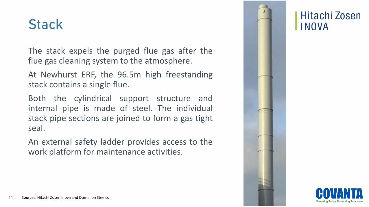
Stack
The stack expels the purged flue gas after theflue gas cleaning system to the atmosphere.
At Newhurst ERF, the 96.5m high freestandingstack contains a single flue.
Both the cylindrical support structure andinternal pipe is made of steel. The individualstack pipe sections are joined to form a gas tightseal.
An external safety ladder provides access to thework platform for maintenance activities.
11 Sources: Hitachi Zosen Inova and Dominion Steelcon

Emissions Measurement (CEMS)
The emission measurement system monitors the fluegas properties and detects the composition in theflue gas duct after the last flue gas cleaning stage orthe stack respectively.
The instruments are installed directly on the flue gasduct. For the gas concentration measurement, asmall flue gas stream is extracted through a heatedextraction line and conveyed to the measurementsystem installed in a separate emission measurementenclosure.
The emission management system is designed tomeet the particular requirements of the operatingpermit for the plant. It complies with the applicabledirectives for installation and quality assurance.
12 Sources: Hitachi Zosen Inova and SICK GmbH

Thank You


