I- I • • • • NORSKE SIVILINGENI0RERS FORENING NORWEGIAN SOCIETY OF CHARTERED ENGINEERS NORTH SEA FLOWMETERING WORKSHOP STAVANGER 13-15 OCTOBER 1987 EXPERIENCE WITH A SMART 11 0P 11 TRANSMITTER Main Index LECTURER: TROND HJORTELANO STA TOIL DRIFTSDIVISJON STAVANGER All rights reserved NIF and the author efl 970.1
Transcript
I- :~ I
•
•
•
•
NORSKE SIVILINGENI0RERS FORENING NORWEGIAN SOCIETY OF CHARTERED ENGINEERS
NORTH SEA FLOWMETERING WORKSHOP STAVANGER
13-15 OCTOBER 1987
EXPERIENCE WITH A SMART 11 0P 11 TRANSMITTER
Main Index
LECTURER: TROND HJORTELANO STA TOIL DRIFTSDIVISJON STAVANGER
All rights reserved NIF and the author
efl 970.1
"
• LIST OF CONTENT
PAGE 1. INTRODUCTION
1.1 Presentation content 1 1.2 Summary 2
2. DESCRIPTION OF INSTRUMENT
2.1 Introduction 3 2.2 Sensing element 3 2.3 Electronics 3 2.4 Communication with the transmitters (SFC) 4 2.5 Summary of the transmitter's main features 4
4. PRACTICAL EXPERIENCE FROM APPLICATION OF ST3000
4 .1 Application area 10 4.2 Results from testing of transmitters 10 4.3 Summary and conclusion for field experience 14
5. FUTURE TRENDS IN PROCESS MEASUREMENT 15
•
• efl 970.2
- 1 -
EXPERIENCE WITH A ST3000 SMART TRANSMITTER
1. INTRODUCTION
1.1 Presentation content
This presentation will include test results and experience in application of Honeywell ST3000 smart pressure transmitters. Both differential pressure and static pressure transmitters have been uti l tzed on the Statfjord field since early 85.
The transmitters are installed in fiscal gas metering stations for measurement of differential pressure and line pressure in orifice meter runs.
The gas · is fed to the Statpipe system on Norwegian sector and to NLGP/FLAGS on the UK sector.
The main objective with the presentation is to sununarize experience from the following phases:
a) Selection of equipment. b) Installation and commissioning. c) Operation.
The comments are made based on experience from personnel involved with maintenance work.
The main references for the overall quality of the transmitter will be based on the following:
a) High accuracy b) User friendly c) Availability d) Re 1 i ab i1 i ty e) Stability in calibration
1.2 Summary
1.2.1
efl 970.3
Description
The transmitter features a new concept in the measurement of process parameters. Communication via its 4-20 mA loop makes this transmitter unique and provides the capabilities of remote transmitter adjustments and diagnostics. This is accomplished via a hand held communicator and enables the operator to perform changes in transmitter configuration from the control room.
The sensor is a piezo resistive element and microprocessor based electronics provide enhanced accuracy by compensation of output signal (temperature and static pressure compensation for differential pressure measurement).
I .#1., '
•
•
•
•
1.2. 2
efl 970.4
- 2 -
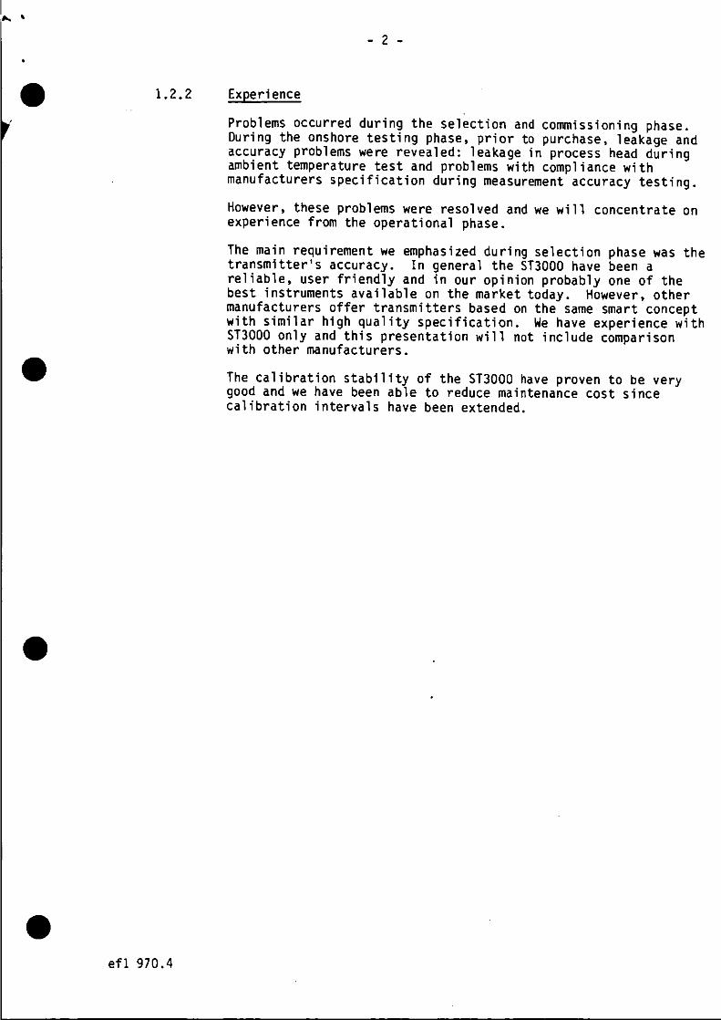
Experience
Problems occurred during the selection and conunissioning phase. During the onshore testing phase, prior to purchase, leakage and accuracy problems were revealed: leakage in process head during ambient temperature test and problems with compliance with manufacturers specification during measurement accuracy testing.
However, these problems were resolved and we will concentrate on experience from the operational phase.
The main requirement we emphasized during selection phase was the transmitter 1 s accuracy. In general the ST3000 have been a reliable, user friendly and in our opinion probably one of the best instruments available on the market today. However, other manufacturers offer transmitters based on the same smart concept with similar high quality specification. We have experience with ST3000 only and this presentation will not include comparison with other manufacturers .
The calibration stability of the ST3000 have proven to be very good and we have been able to reduce maintenance cost since calibration intervals have been extended .
- 3 -
2. DESCRIPTION OF INSTRUMENT
Ref. Fig. 1 and specification sheets.
2.1 Introduction
The intention is not to fully describe all the details of the transmitter's features and functions. Please refer to the technical manual for details.
This presentation will concentrate on the transmitters main new features.
The ST3000 microprocessor based transmitter performs measurement of differential, gauge or absolute process pressure. The piezo resistive sensor combined with the microprocessor based electronics and digital to analog converter provides an analog 4-20 mA output signal proportional to the measured signal.
The ST3000 was ·designed as a direct replacement for conventional analog transmitters. It uses the existing 4-20 mA lines for power, signal transmission and conununication. t One of the new main features include remote corrmunication with the transmitter through the Smart Field Communicator {SFC). This unit provides the capabilities of remote adjustments and diagnostics.
The ST3000 family includes instruments for a wide range of application areas with measurement of the following process parameters:
a) Absolute pressure b) Gauge pressure c) Differential pressure
This presentation will concentrate on the measurement of differential pressure.
2.2 Sensing element
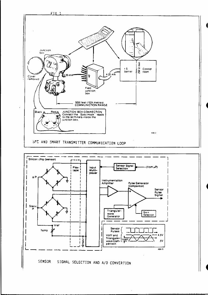
The ST3000 transmitter utilize a piezo resistive sensor with no mechanical parts.
The piezo resistive straingauge sensor is an electric wheatstone bridge circuit ion-implanted onto a silicon chip. The sensor is sealed and isolated from the process by metal diaphragms and silicone fluid.
This integrated sensor provides three analog signals; process pressure, sensor temperature and static pressure.
These three analog signals are converted to digital signals for input to the microprocessor. The processor utilizes factory calibration data stored in PROM and calculates appropriate output values, compensating for the existing temperature and static pressure conditions.
This value is then converted back to an analog signal, resulting in an 4-20 mA output signal.
efl 970.5
•
•
•
•
- 4 -
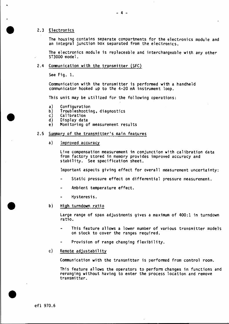
2. 3 Electronics
The housing contains separate compartments for the electronics module and an integral junction box separated from the electronics.
The electronics module is replaceable and interchangeable with any other ST3000 model.
2.4 Conmunication with the transmitter (SFC)
See Fig. 1.
Conmunication with the transmitter is performed with a handheld communicator hooked up to the 4-20 mA instrument loop.
This unit may be utilized for the following operations :
a) Configuration b) Troubleshooting, diagnostics c) Calibration d) Display data e) Monitoring of measurement results
2.5 Summary of the transmitter's main features
a) Improved accuracy
Live compensation measurement in conjunction with calibration data from factory stored in memory provides improved accuracy and stability. See specification sheet.
Important aspects giving effect for overall measurement uncertainty:
Static pressure effect on differential pressure measurement.
Ambient temperature effect.
Hysteresis •
b) High turndown ratio
Large range of span adjustments gives a maximum of 400 :1 in turndown ratio.
This feature allows a lower number of various transmitter models on stock to cover the ranges required.
Provision of range changing flexibility .
c) Remote adjustability
efl 970.6
Communication with the transmitter is perfonned from control room.
This feature allows the operators to perform changes in functions and reranging without having to enter the process location and remove transmitter .
- 5 -
d) Diagnostics and start up
The concept of remote communication is timesaving in diagnostics work.
e) Commissioning
efl 970.7
The transmitter may be utilized as a current generator and thereby commissioning on total loop work may be completed in a shorter time.
In general the remote comnunication concept provides great improvement during commissioning and startup work where configuration changes are required to "tune'' the process.
In our application ranges are fixed and thereby the possibility of reranging does not apply for our present installation .
- 6 -
• 3. CALIBRATION. METHODS ANO PROCEDURES
•
•
•
3.1 Requirement
Fiscal measurement of petroleum products has to comply with regulations from authorities. Norwegian Petroleum Directorate has issued regulations for gas:
Regulation for fiscal measurement of gas produced in internal waters, in Norwegian territorial waters and in the part of the Norwegian Continental Shelf which is subject to Norwegian sovereignty.
In these regulations it is stated (§63) that calibration intervals for transducers are every month. Based on experience wiht equipment, dispensation from regulations may be granted.
Additionally, industrial practice within custody transfer set requirements for gas sales.
The calibration method and procedure should be approved (recognized) by authorities, partners and buyers.
3.2 . Differential pressure and static pressure
3.2.1
3.2.2
efl 970.8
Introduction
The differential pressure (DP) is a vital parameter in an orifice measurement system. We have therefore emphasized the importance of the quality of the OP-measurement in order to keep the overall station measurement uncertainty as low as possible.
The static pressure measurement is utilized in secondary correction to the gas flow measurement. However, it is considered to be an important parameter and we have therefore aimed for high quality instrumentation during selection phase of test equipment and transmitter.
The following description gives an outlined version of the detailed calibration procedures and test equipment.
This procedure is included in the
Gas Metering Calibration and Maintenance Manual for The Statfjord Field
Test and calibration work is perfonned both offshore and onshore (DP). For static pressure we perfonn calibration offshore only.
Testing and calibration
Requirement
All fiscal measurement will require test equipment with very high accuracy and certified traceability to national standards •
efl 970 . 9
- 7 -
Requirement for onshore calibration:
0-100 mbar: 0-500 mbar :
Traceability
0.2 75% 0.15%
For differential pressure measurements we have certified traceability to the French National Standard via LNE (Laboratorie National d'Essai}
For voltage measurement (measurement for transmitter output across a precision resistor) we have certified traceabil i ty to the British National Standard via NPL (National Physica l Laboratories).
Equipment. Differential Pressure
Ref. fig . no. 2.
Onshore
Des Granges et Huot pressure standard 5303 Des Granges et Huot devider 1500
This system features the capability of applying differential pressure to the transmi t ters at a given static pressure.
Voltage & Resistor
Voltage measurement: Precision resistor:
Solartron 7081 Cropico RS3
The transmitter (4-20 mA) output is measured across a 250 precision resistor.
Off shore
Pressure
AMETEK pneumatic OWT.
Voltage & Resistor
Solartron 7150 Precision resistor for computer input (250
Outlined procedure for differential pressure
The calibration procedure for differential pressure transmitter includes 5 different tests.
Onshore (test lab)
1) Atmospheric test
This test includes verification of differential
•
•
•
• efl 970 . 10
2)
- 8 -
range at atmospheric pressure. The objective is to monitor calibration shift between onshore testing. No adjustments.
Calibration at static pressure
The transmitter is calibrated at operational static pressure. Adjustments may be perfonned.
3) "Footprint test"
A "footprint" of the transmitter's range·at atmospheric pressure is recorded.
NB: No adjustment is performed.
Off shore
1) Offshore "footprint" verification test
This includes a verification of the transmitter's 11 footprint 11 established onshore. This is done after the transmitter is installed.
The objective is to verify that no calibration shift has occurred during transportation from shore to platfonn.
If the 11 footprint 11 test is completed and results are within the set tolerance the transmitter is put in use.
2) Offshore "footprint" as found test
The test includes a verification of the transmitter's "footprint" after it has been used in process.
The objective with the test is to monitor output stability.
This test completes the period for the transmitter and it will be sent to shore for testing as stated under previous paragraph.
Testing is perfonned at 5 different points over the transmitter's range.
Outlined procedure for static pressure transmitters
These transmitters are calibrated offshore only (installed in the process) .
Equipment
Pressure reference
AMETEK DWT (hydraulic) .
efl 970 .11
- 9 -
Voltage measurement
Sol artron 7150.
Procedure
Pressure is applied to the transmitter with the dead weight tester and transmitter output is measured in the control room across a 250 precision resistor at flowcomputer input.
Testing is perfonned at 5 different points over the transmitter's range.
- 10 · -
• 4. PRACTICAL EXPERIENCE FROM APPLICATION OF ST3000
•
•
•
4.1 Application area
4.1.1 Process parameters and installation
Honeywell ST3000 transmitters are utilized in fiscal gas metering stations for measurement of differential pressure (DP) and line pressure in orifice meter runs.
Fiscal metering of gas on the Statfjord field includes 4 metering stations.
Statf jord 11A11
Statf jord "B" Statpipe
Sta tf jord "B" UK-Of ftake
Statf jord 11 C11
No ST3000 OP
6
4
4
4
No ST3000 Line Pressure
3
2
2
2
Capacity of Station Approx (MSm3/0)
7.67
5. 5
3.0
5.5
The flow measurement is perfonned in accordance with ISO 5167.
The applied ranges and estimated uncertainty for the transmitters are listed in table 1. Differential pressure measurement across the orifice plate is perfonned with two transmitters per meter run.
Table 1
DP Transmitter A DP Transmitter B
Line pressure transmitter
Range
0-100 mbar 0-500 mbar
0-250 bar
Est. Uncertainty(%)
0.3 0.2
. 0.25
4. 2 Results from testing of transmitters
Prior to start up of Gas Sales from Statfjord the Operator (Mobil Exploration) perfonned a market survey in 1983 in order to select a high quality differential pressure transmitter. The uncertainty of measurement was emphasized and was considered to be the major checkpoint .
Honeywell supplied 3 ST3000 transmitters for testing.
The main objective with this test was to verify the manufacturers uncertainty specification including the output shift with varying static pressure .
efl 970 .12
4.2.l
4.2.2
efl 970.13
- 11 -
Conclusion from market survey
The test revealed problems for one of the ST3000 test objects; it was found to be outside manufacturers specification.
However, the overall evaluation of the transmitters main features concluded that a cooperation should be established with Honeywell. The test objects were of the very first generation and further testing convinced us that we should choose 513000 for the gas metering stations.
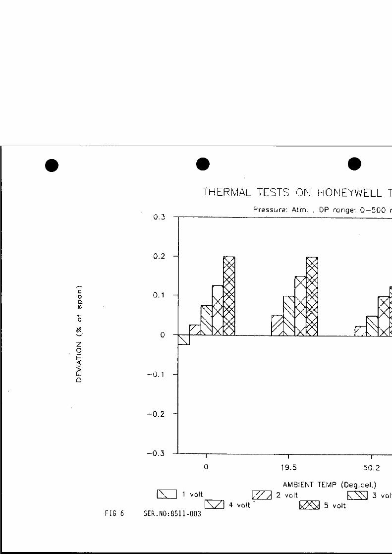
Test results from ambient temperature effect on DP measurement
In order to verify ambient temperature effect on differential pressure measurement it was decided to test 4 ST3000 DP-transmitters at various ambient temperatures.
Test Arrangement
The four transmitters were located in a thermal test chamber. ~
Pressure was applied (differential pressure over the transmitters range at a given static pressure) from a conmen pressure source. Transmitter output values were monitored with a digital voltmeter hooked up across a 250 resistor.
Monitoring of temperature in chamber was performed with a tenno couple probe.
All test instruments have traceability to National Standards (UK).
Test procedure and objectives
The objective was to evaluate tge tran~mitter measurement results over the temperature range of O C - 75 C at differential spans of 100, 200, 500 and 1000 mbar.
Calibration of transmitters were perfonned at room temperature and at 140 bar and atmospheric pressure. The upper range values ~ were set before conmencing the test at the four differential pressure spans.
Transmitters were expossd to ~ differe9t ambient temperatures; nominal values: o0 c, 20 C, 50 C and 75 C.
The transmitters output results were recorded at each of the temperatures and at static pressures of 140 bar and atmospheric for the applied differential pressures over the range at 01, 25%, soi, 75%, lOOt and 110% and the same testpoi nts down. This was done for all 4 spans .
The discrepancies from the ideal value is presented in bar diagram.
We have attached results only for 2 transmitters from 4 tests.
Conclusion
Severe leakage problems in process head were revealed at o0c ambient temperature with three transmitters. The torque setting of the bolts were checked and the problem was rectified.
The manufacturers excuse to this problem was explained with the torque setting during the assemblance at the factory. Their quality assurance/quality control system obviously needed some improvement.
1 transmitter failed at a temperature in excess of so0c. With these described failures in mind users start to ask questions about the quality of the cells .
All our cells were checked for correct torquesetting and pressure tested {a calibration verification}.
The ambiegt temperature in our application will most likely not exceed 58 C, so the overall conclusion will be based on the tests below 50 C.
If we exclude the leakage problem and failure for 1 cell at 75% the overall results from the test is good and may be summarized with the following values:
In general the temperature effect was better tgan ! 0.2% of calibrated range for a temperature range of 50 C. However, one cell indicated output within + 0. 3 of span over the same temperature range. -
This test verified that the quoted estimated uncertainty in OP measurement was achieveable •
Test performed by other laboratories
Other independent test laboratories have perfonned testing on the ST3000 and the general conclusion is that the cells operates within manufacturers specification.
Stability in calibration
Ref. fig. 7-12, table 2 and calibration procedures.
The attached graphs represents comparison in test results from onshore calibration at static pressure and the "footprint" of the transmitter from one period to the next .
- 13 -
The results are presented as difference in output in% of span from one period to the next.
Two DP-cells and one gauge pressure transmitter are included in this presentation. These are typical for the transmitters in operation on Statfjord.
Conclusion
The transmitters have proven to be extremely stable in calibration. We have therefore reduced maintenance cost since the calibration intervals have so far been increased from every month to every second month, and foresee 3 monthly intervals in the future.
Table for transmitter monitoring :
Table 2
No. of No. of Range Ser . no. Time in use Tests Adjustm.
DP Transmitter A 0-500 mbar 8525-004 Aug 85-Apr 87 8 1 at zero DP Transmitter B 0-100 mbar 8511-020 Jul 85-Apr 87 7 1 at zero
of span P Transmitter C 0-250 bar 8510-031 8 months 8 None
efl 970 .1 5
t
•
•
•
•
- 14 -
4.2.5 Reliability and availability
After approximately 2.5 years months in operation with ST3000 we have had no downtime due to transmitter failures .
The transmitters have proven to be very reliable and based on our experience the availability rating is very high.
4.3. Su1T111ary and general conclusion for field experience
efl 970.16
We faced some problems during the early stages of ST3000 applications and over the time the conununication with the Honeywell vendor contained some negative statements concerning the quality of the transmitters.
However, these problems were resolved and the cooperation have been very good.
Comparing the transmitter with conventional instruments it was certainly a great improvement within process measurement field.
The transmitters have proven to be user friendly, reliable and the stability in calibration is very good .
The present calibration concept is under evaluation and based on the good quality of the instruments the calibration procedure may be simplified .
- 15 -
5 FUTURE TRENDS IN PROCESS MEASUREMENT
The future trends within the transmitter field indicates several new important developments . To our knowledge Honeywell was the first manufacturer who
_released transmitters with the smart concept. Since then other manufacturers have introduced transmitters with similar specifications.
For the pressure measurement the trend seem to divert into application of quartz
crystal in standard field instruments for the process industry.
Application of microprocessors require digital techniques. Transmission from field to control room is perfonned via an analog signal. This requires O/A and A/0 converters.
The new systems includes the option of digital transmission and thereby improves overall loop uncertainty.
Application of "intelligence'' (microprocessors) in the primary elements is a very important improvement and is utilized for a number of different process parameter measurement . In future applications this concept will be applied to a large extent.
This will improve measurements and probably contribute to lower maintenance cost.
efl 970.17
•
•
•
•
Spec I II cation 34-ST·03·01 Page 2
Specifications Operating Conditions
Ambient Temperature oc OF
Meter Body Temperature oc •F
Humidity %
Supply Voltage end Load Reeletance
Reference Condition
25 ± 1 77 ± 2
25 ± 1 77 ± 1
10·55
See Figure 2.
ST 3000 DIFFERENTIAL PRESSURE TRANSMITTER
1984 SPECIFICATION
Rated Operative Transportation Condition Limits and Storage
-40 to 85 - 40 to 93.3 -55to125 - 40 to 185 - 40 to 200 - 67 to 257
-40 to 110· - 40 to 125 - 55 to 125 -40 to 230 - 40 to 257 - 67to257
0· 100
OverpreHure psi _o ______ _ 3000 psi 3000 psi
In Vacuum Region mm Hg Ab• atmospheric atmospheric to 25 atmospheric to 2
Performance Under Rated Conditions Upper Range Limit
Tumdown Ratio
Minimum Span
Zero Elevatlon and Suppreaalon
Accuracy (Reference) (lncludee combined effects of llnearlty, hyaterHls, and repeatablllly)
~ Combined Zero end Span Temperature Effect per 2a•c (50°F)
.t, Combined Zero and Span Static Preaaure Effect per 1000 pal
400:1
Regardless ol output specified. zero elevation and suppression must be such that neither the span nor the upper or lower range value exceed 100% of the upper range limit. 4·20 mA de maximum elevation: 40,000% of calibrated span. Maximum zero suppression: 39.900% of calibrated span.
± 0 . 1 % of calibrated span or upper range value. whichever is greater. terminal based. NOTE: Below 50 in H20 accuracy equals
o.os + (0.05 x 50 i~ H20 )
span 1n H10 ± 0.25% of c alibrated span, between reference span and Upper Range Limit.
NOTE: Below 50 in H20 accuracy equals
o.2 + (0.05 x 50 ;~ H10 ) span 1n H10
± 0.2% o f the calibrated span. between reference span and Upper Range Limit. NOTE: Below 100 in H20 accuracy equals
0 .2 { 100 in H20 ) span rn H20
Hyatereela % of Span 0.02 --'-------'-----~ Output (two.wire) 4 to 20 milliamps
Supply Voltage Effect 0.005% of span
Damping Tim• Conatant Adjustable from 0 to 32 seconds
RFI Protection (Standard) 20 to 1000 MHz at 30 volts per meter
Physical Materlal1
Process Interface
Mount ing Bracket
Fill Fluid
Electronic Housing
Proceu Connection• .
Process Barrier Diaphragms: 316 S.S .. Hastelloy C-276. Monel Process Head: 316 S.S .. Catbon Steel . Monel, Hastelloy Head Gaskets: Teflon Bolting: Carbon steel. 17 ·4 PH stainless steel
Carbon Steel (zinc plated)
Silicone oi l or fluorolube
Low Copper Aluminum Meets NEMA 4 (watertight) and NEMA 7 (explosion-proof)
Wiring 1/4 inch NPT (optional 1/4 inch Pn
Accep1s up to 16 AWG (1 .5 mm diameter) ----'--'------'-------:......:....----------------- ·----Mounting
Dimensions . .Net Weight
Hazardous Conditions
See Figure 3. · - ---· ----
See Figure 4 .
~-~g (15.4 pounds) ·---------Designed to meet requirements of explosion-proof and intrinsically safe systems for North American classificat ions Class I. Group A, 8 , C. and D . Division I and European EEX. 1a. II. C . T6. Contact Fort Washington for approval body codes
· For fluoroluoe l ill fluid. lhe ra ting is - 15 10 11o•c (5 to 230°F).
Specification 34-ST-<13·01/E ST 3000 DIFFERENTIAL PRESSURE TRAN SM ITTE R Page2
1987 SPECIFICATI ON (
Specifications , Operating Conditions
f
Reference Rated Operative Tranapor1atlon Condition Condition Llmltl and Storage -
Ambient Temperatvre ·c 25 ± 1 -4010 85 -40to93 -55 to 125 .. ' F 77 ± 2 -40to 185 - 40 to 200 -67 to 257 ---- ---
Mtlter Body Temper.iure ' C 25 ± 1 -40to 110· -40to 125 -55 to 125 ' F 77 ± 1 -40to230 -40to257 - 67 to 257 - - -·- .
~mlcllty ___ . "· 10-55 0-100 0-100 0-100 Supply Voltage and (See Figure 2.) load Realatance --~- -O"Yerprea~!..._. psi 0 3000 psi (210 bar) 3000 psi (210 bar) In Vacuum Region (Min Preat.I mm H9 Ab• atmospheric 25 2 (Short term)
Performance Under Rated Conditions Upper Range L~mft 400 in H20 ( 1000 mbar) Turndown Ratio 400:1 ~· --- ... .. Mln~um~ 1 in H20 (2.5 mbar)
{ Zero Elevation tnd No limit (except minimum span) within ± 100% URL. Specifications valid from - 5% to Suppre~·~~!' +100% UAL. Accuracy (Referencel Analog Mode : ±0 10% calibrated span or upper range value (URV). whichever is greater. (Include• comblnecl effect• terminal based. of Une1rlty, 1ty1tereel1, and For UAV below reference span (25 in H20) accuracy equals : repeatablllty)""1 ( 25 in H,O ) ( 0 .05 + 0.05 x span in H
20 or 0 .05 + 0.05 x 62 mbar ) ·
span mbar rn % span
Digital Mode : ±0.0 75% span / ±0.15% reading See Digital Communications Mode Specification 34-ST-03-27 for e)(planat ions of transmitter accuracy and system accuracy.
t Combined Zero and Span Analog Mode : ± 0. 175% of span. Temperature Eff9Ct per 28°C For UAV below reference span (50 in H20) effect equals : (SCl°F)'" ( 50 in H2 0 ) { 1 25 mbar } .
0.125+ 0.05xspaninH20 or0.125+ O.OS x spanmbar 1n%span
, I
Digital Mode : ±0.125% readi ng For readings betow reference span (50 in H20) effect equals :
0 .0 75 + (o.os x 50 in H20 ) { 125 mbar } . . rdg in HzO or 0.075 + 0.05 x rdg mbar 1n 'ro reading
Combined Zeto end Span Analog Mode : ± 0.2% of span, except 0.2 in H20 (0.5 mbar} minimum. Static Preuure Effect per Typical performance is ±0.1 % . except 0 .06 in H20 {0.15 mbar) minimum with stainless steel 1000pal diaphragms.
Digital Mode : Same except in % reading Output (twe>wire) 4 to 20 mil Ii amps. or digital communications mode Supply Volt1ge Elfect 0.005% of span per volt (
Damping Time Con1t1nt Adjustable from Oto 32 seconds digital damping RFI Protection lStandard) Neglig ible effect (20 to 1000 MHz at 30 volts per meter)
Physical Materials
Process Interlace Process Barrier Diaphragms : 316L SS. Hastelloy C-276. Monel, Tantalum Process Head : 316 SS. Carbon Slee I. Monel, Hastelloy Head Gaskets : Teflon. Viton Bolting : Carbon stee l. A-286 SS (NACE)
Mounting Bracket Carbon Steel (zinc plated) Fill Fluid Silicone oil or CTFE (chlorotrifluoroethylene) Elec tronic Housing Low Copper Aluminium
Meets NEMA 4 (watertight) and NEMA 7 (explosion-proof) ProceH Connextlona 1 /4 inch NPT (optional 1/2 NPT with adapter) Wiring Accepts u p to 16AWG (1.5 mm diameter) Mounting (See F ig ure 3 .) Dlm•n•lons (See Figure 4 .) Net Weight 7 Kg ( 15.4 pounds} Ha:urdoua CondltloM Designed to meet requirements of explosion-proof and intrinsically safe systems for North
;
American c lassificat ions Class I. Groups A. B. C and D. Div ision (explosion=R,roof systems. Groups B. C. D only), European (CENELEC) EEX. ia. llC. T6 and BASEEFA ype N.
.. For CTFE 1111 11u10. the rating is -1 5 to \ 1o•c (5 to 230"F). •. Spec1fica11on does not apply to ST 3000 with tanlalum barrier diaphragms . t Accuracy includes res idual error after averaging successive readings.
t
•. ST 3000 GAUGE PRESSURE TRAN SM I TTE R
Specification 34·ST·03·06 1987 SPECIFICATION
• Page 2
• 4 Specifications 4 Operating Conditions
Reference Rated Oper1tlve Tranaponatlon Condition Condition Limit a and Storage --·-·- --- - - - -
Ambient Temperature •c 25 ± l - 40 to 85 - 40 10 93.3 -55 to 125 •F 77 ±2 - 40 10 185 - 40 to 200 - 67 to 257 - -- -··- ·-· - --
Meter Body Temperature •c 25 ± 1 -40to110· - 40 to 125 - 55 to 125 •F 77 ± 1 - 40 to 230* - 40 to 257 - 67 to 257 -- ---- -
Humidity % 10-55 10·90 0-100 - ·- · ···----Supply Voltage and See Figu re 2. Load Resistance - -- ... Overpressure psi 0 9.000 psi (620 bar) 9,000 psi (620 bar) - - ·· - ---- ·-In Vacuum Region
mm Hg Aba atmospheric atmospheric to 25 atmospheric to 2
Performance Under Rated Conditions .
Upper Range Limit 6.000 psi (4 l 5 bar) • ·- - ----4 Turndown Ratio 60:1
- --· Minimum Span 100 psi (7 bar) - -----Zero Elevation and Regardless of output specified. zero elevation and suppression must be such that neither the Suppression span nor the upper or lower range value exceed 100% of the upper range limit.
Maximum Zero Elevarion: 14.7% of calibrated span. Maximum zero suppression : 5.900 % of calibrated span.
-- -- . - . Accuracy (Reterence) ± 0.15 % of calibrated span or upper range value. (URV) whi chever is greater, terminal based. (Includes combined effects NOTE: For URV below 1000 psi accuracy equals of linearity, hysteresis, and
0.10 + (o.os x 1000 psi )
0.10 + (o .o5 x 70 bar ) 4 repeatability) or span in psi Span in bar
----·· - · ·-Combined Zero and Span 0.25% of calibrated span. Temperature Ellect per 28°C NOTE: For UAV below 1000 psi effect equals (50°F)
0.2 +- (o.os x 1000 psi )
0 .2 + (o.os x 70 bar
) or span in psi Span in ba r
Output (two·wire) 4 to 20 miltiamps -----·· Supply Voltage Effect 0.005% of span per volt --------Damping Time Constant Adjus.table from 0 to 32 seconds digital damping
RFI Protection (Standard) Negligible (20 to 1000 MHz at 30 volts per meter)
• Physical 4 Materials
Process ln1erlace Process Barrier Diaphragms: 316l S.S .. Hastelloy C-276, Mone! Process Head: 316 S.S .• Carbon Steel Head Gaskets: Teflon, Viton Bolting:Carbon steel, 17-4 PH stainless steel
Mounting Bracket Carbon Steel (zinc plated)
Fill Fluid Silicone oil or fluorolube
Electronic Housing Low Copper Aluminum Meets NEMA 4 (watertight) and NEMA 7 (explosion·proof)
-· Process Connections 112 inch NPT
Wiring Accepts up to 16 AWG (1.5 mm diameter)
Mounting See Figure 3.
Dimensions See Figure 4.
Net Weight 6.5 Kg (14 pounds)
t Hazardous Conditions Designed to meet requirements of exptosion·proof and intrinsically safe systems for North American classificat ions Class I. Group A. B. C. and D. Divis ion I and European (CENELEC) EEX. ia. llC. T6 . Contact Fort Washington tor approval body codes.
·For Fluorolube till fluid the rating is - 15 to 110°c (5 to 230 °F) . • •
Junc hon
f I G !
1unc11on box
I 5000 feet (1524 metresl ~ COMMUNICTION RANGE
JUNCTION BOX CONNECTION Connect the " Easy Hook" leads to tl'le terminals inside the junction box .
I$ t>amer
e e oc Colltrol ~ room
•lO·l
SFC AND SMART TRANSMITTER COMMUNICATION LOOP
Temp
I I I I I I I I I
I I I L_ __ ,
Input Multiplexer
-------, ae----t Sensor Signal ---(from ,.P)
Selection
Instrumentation Ampllller
Sensor Pulse Signal
I I I I I I l I
Triangular- Ga io I wave Selection Generator J
r.:--------sensor { ---,-n-n-r Pulses _LJ_LJ_L.J_
Vdilf and { * -1\-1\-.1\--; 4.5V TrianQular- Vdiffz SI svr~ 5V wave Com- r -- -- -- . parl son
L-----------.J 420-11
SENSOR SIGNAL SELECTION AND AID CONVERTION
•
•
•
•
Schematic
1) PRESSURE
2)
Connecting tube
Oil-operated standard Type 5300
ELECTRICAL
1' POWER SUPPLY
4- 20 mA output
Transmi tter
FIG 2
DIVIDER MODEL 1500
Installation Schematic ----------------------
Instrument to be calibrated
0
Di vider Mode l 1500
Cropico RS 3
Precision Resistor (250 OHM)
Calibr ation hook-up fi g .
Gas pressure sou
So 1 ar.tron 7081
--.J ... ~
en
0
~~ .... _ 7
•J -t--•{
> w •. ::i
•
. "?. V . ...J
0.2
0. 1
J
-0.1
-0.2
-0.3
-0.4
-0.5
THERt\1Al_ TE'3T: t)~I HOf\J[.(NELL Tf
,, ' , (
'·
"
1~I.2 Su.1
J>.MBIEtH TDAP (Ceq.c e1. :,
V.)lt
FIG 3 • SER •. NO; 8525-008 •
• • • Fr~s::.urd: 1-ti:) bor. JP ran:Je: 1)-1::)) rr