NEW MEXICO DEPARTMENT OF TRANSPORTATION State Materials Bureau Geotechnical Engineering & Exploration Section NMDOT Proprietary Earth Retaining Systems Evaluation and Approval Process September 2017
Transcript
NEW MEXICO DEPARTMENT OF TRANSPORTATION State Materials Bureau
Geotechnical Engineering & Exploration Section
NMDOT Proprietary Earth Retaining Systems Evaluation and Approval Process
September 2017
NMDOT Proprietary Earth Retaining Systems Evaluation and Approval Process
1
INTRODUCTION The New Mexico Department of Transportation (NMDOT) has developed this Proprietary Earth Retaining Systems (PER Systems) Evaluation and Approval Process in order that Proprietary Earth Retaining (PER) Systems may be approved by the NMDOT based on the guidelines herein and listed on the Materials Bureau List of Approved Systems (PER-LAS) with or without restrictions. The current List of Approved Systems is posted on the State Materials Bureau Webpage (http://www.dot.state.nm.us/content/nmdot/en/Operations.html#d). A PER System Evaluation Report will be developed by an independent Review Engineer. The PER System Evaluation Report will be reviewed by the NMDOT PER Committee. The elements of a PER System are multidisciplinary involving structural, geotechnical and administrative aspects. Therefore, representatives from each of those disciplines are required for the review process of the PER System Evaluation Report. The NMDOT PER Committee will be made up of Bureau/Section heads from the Bridge Design Bureau and Geotechnical Design Section as well as the State Materials Bureau. The Bureau/Section heads may assign an engineer from each of their representative disciplines to serve on the committee. The NMDOT PER Committee establishes the Procedures to Evaluate Proprietary Earth Retaining (PER) Systems and also serves to implement its decisions through the Section 506 of the NMDOT Standard Specifications for Highway and Bridge Construction (2014) and Special Provisions Modifying Section 506 as needed. Specifications are posted on the State Materials Bureau webpage. The PER Systems document is established to govern and standardize the submittal, review and decision process for PER Systems and is posted on the NMDOT State Materials Bureau webpage (http://www.dot.state.nm.us/content/nmdot/en/Operations.html#d) so that it is clearly documented what will be required to achieve and maintain acceptance of a PER System on the NMDOT State Materials Bureau PER-LAS. Failure to comply with the PER Systems requirements are grounds for rejection for inclusion on the PER-LAS. The PER-LAS will be maintained in accordance with the PER Systems process as the list of PER Systems who may be used by contractors bidding on Department projects with PER Systems specified. NMDOT PROPRIETARY EARTH RETAINING SYSTEMS EVALUATION AND APPROVAL PROCESS
1. General 2. PER System Review Process 3. Design and Construction Specifications 4. PER System Submittal Requirements 5. PER System Evaluation Report Requirements and Qualification Requirements of
the Review Engineer 6. PER System Renewal Requirements 7. PER System Performance 8. Approval Process for New PER Systems or Currently Used by NMDOT
NMDOT Proprietary Earth Retaining Systems Evaluation and Approval Process
2
1. General. The NMDOT PER Systems document governs the process for approval of PER Systems and inclusion on the PER-LAS. Both permanent and temporary PER Systems will be limited to the following categories:
Category A - Precast Gravity, Semi-gravity, Bin and Crib Retaining Wall Systems Category B - Gravity Modular Block and Gravity Large Block Retaining Wall Systems Category C - Mechanically Stabilized Earth (MSE) Retaining Wall Systems
The following PER Systems will be restricted from the following design applications:
Category A (Bin and Crib) – No Traffic or Bridge Load Influence Category B – No Bridge Load Influence Category C (Extensible Soil Reinforced and Block MSE) – No Bridge Load Influence
PER Systems employ unique design and construction requirements that are specific to a particular PER System. A PER System Evaluation Report shall identify all unique features of the PER System and highlight exceptions taken by the particular PER System to the AASHTO LRFD Bridge Design Specification. PER Systems are responsible for the “Internal Stability” design and detail requirements of the System. Internal Stability Includes:
• Wall facing stability; connection strength • Pullout resistance of soil reinforcements • Allowable stress of soil reinforcements
“External Stability” requirements are the responsibility of the NMDOT based on the geotechnical conditions of each site application of the PER System. External Stability includes:
• AASHTO LRFD Extreme and Service global and slope stability • AASHTO LRFD Factored and Service bearing resistance • Total and differential settlement • Surface and subsurface drainage requirements
2. PER System Review Process. For a PER System to be placed on the NMDOT PER-LAS,
the following minimum requirements must be met by the PER System: A. To be placed on the NMDOT PER-LAS, the PER System shall be reviewed and
evaluated by an independent Registered Professional Engineer, hereafter referred to as the Review Engineer. The Review Engineer will develop the PER System Evaluation Report. If the PER System has a current American Society of Civil Engineers (ASCE) - Highway Innovative Technology Evaluation Center (HITEC) report available, the HITEC
NMDOT Proprietary Earth Retaining Systems Evaluation and Approval Process
3
report may be included as an attachment to and referenced within the PER System Evaluation Report, but will not replace the independent PER System Evaluation Report. Qualification requirements for the Review Engineer are provided in Section 5. The PER System Evaluation Report shall be submitted to the NMDOT PER Committee along with the PER System approval request. With respect to the NMDOT PER Committee review and evaluation, NMDOT will not have any contractual relationship with the Review Engineer. The PER System is responsible for engaging the Review Engineer for the purpose of producing a PER System Evaluation Report at no cost to the NMDOT.
B. Approval of the PER System will be based on a technical review by the NMDOT PER Committee of the entire submission package. The technical review, at a minimum, would entail thorough examination of the PER System design theory, design details, durability, material requirements, QA/QC plan, and recommended construction methods. Constructability, manufacturer support, and system performance on previous projects will also be evaluated. Attachments F, G, and H include submittal requirements for approval of the PER Systems.
C. The PER Committee will make the final decision regarding the completeness and acceptability of the PER System Evaluation Report. The PER Committee will present its recommendation to the NMDOT State Materials Bureau Chief for inclusion of the PER System on the PER-LAS.
. D. The PER System needs to be approved by NMDOT prior to being used on NMDOT
projects. Note that approval of a specific PER System by NMDOT does not constitute approval of other PER Systems being marketed by the PER System. Also note that placement of a PER System on the PER-LAS does not constitute a commitment or agreement by the NMDOT to use the PER System on any NMDOT construction project.
3. Design and Construction Specifications. The PER System shall meet the design and construction requirements of the following specifications and manuals, as applicable:
• AASHTO LRFD Bridge Design Specification, current edition with Interims • NMDOT Geotechnical Design Manual, current edition • NMDOT Bridge Design Manual, current edition • NMDOT Standard Specifications for Highway and Bridge Construction (2014) • NMDOT Special Provision Modifying Section 506,latest revision • Federal Highway Administration (FHWA) Publication No. FHWA-NHI-10-024, Design
and Construction of Mechanically Stabilized Earth Walls and Reinforced Slopes – Volume I, November 2009
• FHWA Publication No. FHWA-NHI-10-025, Design and Construction of Mechanically Stabilized Earth Walls and Reinforced Slopes – Volume II, November 2009
• FHWA Publication No. FHWA-NHI-07-071 Earth Retaining Structures, June 2008
NMDOT Proprietary Earth Retaining Systems Evaluation and Approval Process
4
• Connection strength (ASTM D6638) and seam strength (ASTM D4884) testing for connections with modular block units; pullout resistance (ASTM D6706) and direct shear (ASTM D5321) testing for soil reinforcement (laboratory testing performed by Geosynthetic Accreditation Institute (GAI) accredited test laboratories)
• National Transportation Product Evaluation Program (NTPEP) values for geosynthetic reinforcement
• NMDOT Geogrid Soil Reinforcement – List of Approved Products (NMDOT GSR-LAS) Strength Reduction and MSEW computer software (ADAMA Engineering, Inc.) design parameters
4. PER System Submittal Requirements. The formal submission by the PER System to the NMDOT shall follow the steps in Section 8 (which details the approval process, required information, timeframe for submittals, and the NMDOT review time). The submission shall be in electronic format (searchable pdf) with two hard copies and shall include the following: A. Letter of Intent (LOI) from the PER System requesting approval of the specific PER
System Category. If applying for a new system, include items B thru I of this section with the LOI. If applying for evaluation of a previously approved system with proposed modifications, the letter shall specifically identify all aspects of the PER System that are proposed to be modified after the publication of the latest version of the PER System Evaluation Report in addition to including items B thru I of this section (Attachments A thru E). The letter, sent by email and by regular mail, shall be addressed to: Mr. James Gallegos, P.E. NMDOT State Materials Bureau Chief New Mexico Department of Transportation P.O. Box 1149 Santa Fe, New Mexico 87504-1149 E: [email protected] Phone 505-827-5625
B. Completed Attachment A entitled “Declaration of Proprietorship and Point of Contact”. C. Completed Attachment B entitled “Declaration of Patents and Proprietary Technology”. D. Completed Attachment C entitled “Declaration of Precast Concrete Manufacturers”. E. Completed Attachment D entitled “Affirmation of Notification Responsibility”. F. Completed Attachment E entitled “Authorization for Duplication and Reproduction”. G. PER System Evaluation Report endorsed, signed and sealed by the Review Engineer. H. A sample set of shop drawings for a recently completed project. I. A sample set of AASHTO LRFD analyses and design calculations for the following cases
utilizing MSEW computer software; MSEW versions 3.0 with update 14.94 or later, manufactured by ADAMA Engineering, Inc. The following design cases will be required based on the category of the PER System being submitted:
NMDOT Proprietary Earth Retaining Systems Evaluation and Approval Process
5
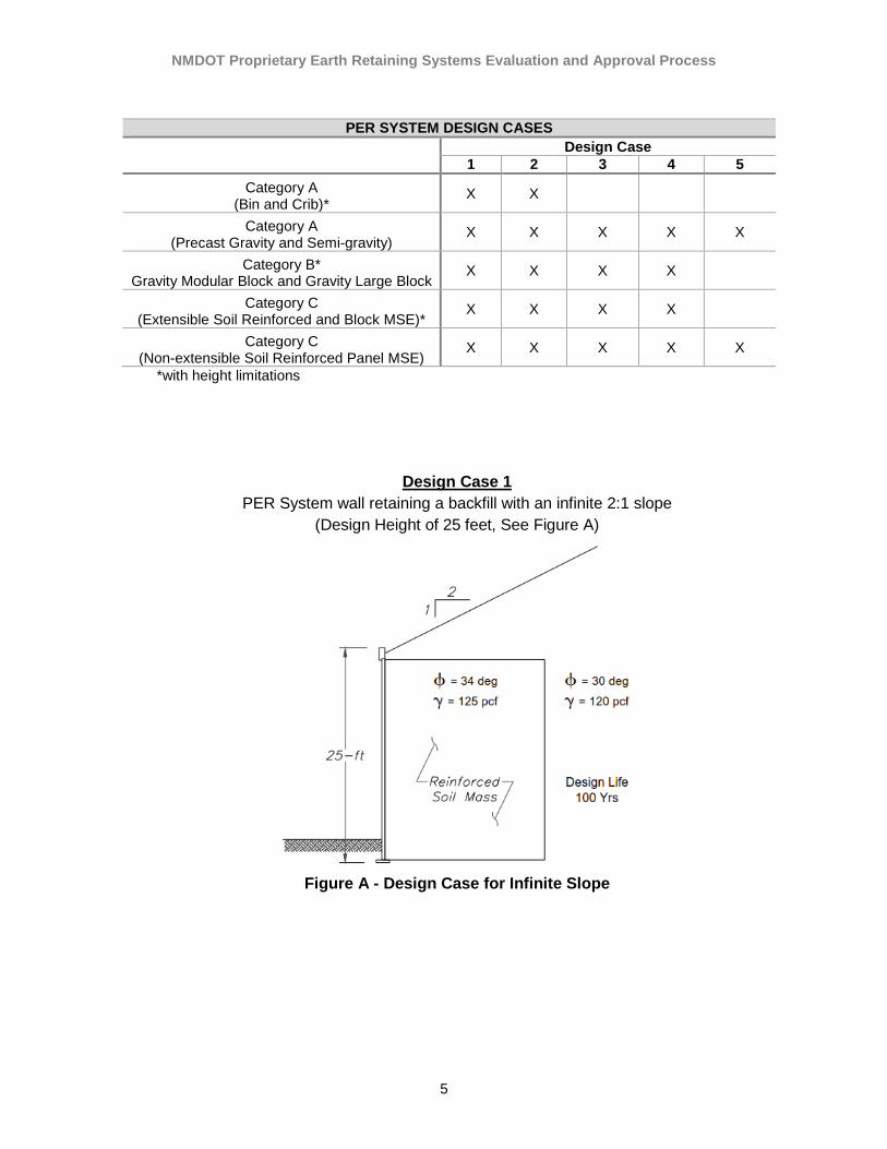
PER SYSTEM DESIGN CASES Design Case
1 2 3 4 5 Category A
(Bin and Crib)* X X
Category A (Precast Gravity and Semi-gravity)
X X X X X
Category B* Gravity Modular Block and Gravity Large Block
X X X X
Category C (Extensible Soil Reinforced and Block MSE)*
X X X X
Category C (Non-extensible Soil Reinforced Panel MSE)
X X X X X
*with height limitations
Design Case 1 PER System wall retaining a backfill with an infinite 2:1 slope
(Design Height of 25 feet, See Figure A)
Figure A - Design Case for Infinite Slope
NMDOT Proprietary Earth Retaining Systems Evaluation and Approval Process
6
Design Case 2 PER System wall retaining a backfill with a 2:1 slope
Breaks to a level backfill at a distance equal to the design height of the wall (Design Height of 25 feet, See Figure B)
Figure B - Design Case for Breaking Slope
Design Case 3
PER System wall retaining a level backfill with and without a live load surcharge (Design Height of 25 feet, See Figure C)
Figure C - Design Case for Level Backfill
NMDOT Proprietary Earth Retaining Systems Evaluation and Approval Process
7
Design Case 4
PER System wall retaining with a back to back wall (Design Height of 25 feet, See Figure D)
Figure D - Design Case for Back to Back Wall
Design Case 5
PER System wall supporting a Bridge Abutment (Wall Height of 25 feet, height to roadway surface of 32 feet, See Figure E)
Figure E - Design Case for Bridge Abutment
NMDOT Proprietary Earth Retaining Systems Evaluation and Approval Process
8
J. Experimental field and laboratory test data supporting the design methodology and the design parameters of the PER System.
K. Design drawings and structural design calculations for all elements of the PER System. L. Documentation that PER System meets the Design and Construction Specifications
listed in Section 3. For any design and construction exceptions taken by the PER System that do not meet the requirements of NMDOT Design and Construction Specifications listed in Section 3, provide a marked-up document, for informational purposes only, highlighting exceptions to the applicable NMDOT Design and/or Construction Specification.
M. A complete list of limitations on the use of the PER System, such as: limiting differential settlement, limiting wall height, alignment turn angles or minimum radius, minimum face batter, abutment applications, etc.
N. Details of typical frames and frame connections utilized to avoid obstructions. O. Detailed repair methods for partial or full replacement of precast concrete elements of
the PER System.
5. PER System Evaluation Report Requirements and Qualification Requirements of the Review Engineer. The Review Engineer performing the evaluation of the PER System shall be a Registered Professional Engineer in the State of New Mexico. The PER System shall submit with the LOI the Review Engineer’s resume and supporting evidence that the Review Engineer has, at a minimum, the following experience: A. Ten (10) years’ experience in the design and construction of analogous PER System. B. Served as the Lead Engineer for the preparation of similar retaining wall designs for a
least five (5) separate publicly funded retaining wall projects. C. Authored or co-authored at least two technical papers that have been published in
professional Civil/Geotechnical Engineering Journals or the following: American Association of State Highway and Transportation Officials (AASHTO) Publications, American Society of Civil Engineers (ASCE) Publications, Federal Highway Administration (FHWA) Publications, or National Highway Institute (NHI) Publications relating to the design and construction of PER System. The technical paper publication requirement stated above can be waived if the Review Engineer has served on any Technical Committee responsible for the development of the design standard or specification including the Design and Construction Specifications listed Section 3 above.
Other than performing the evaluation of the PER System, the Review Engineer shall not have any ownership interests with the PER System, and shall not have served as an employee of the PER System at any time during the last five years. Any conflict of interest between the Review Engineer and the PER System may result in the rejection of the PER System Evaluation Report.
NMDOT Proprietary Earth Retaining Systems Evaluation and Approval Process
9
The PER System Evaluation Report shall address all items included in the applicable Attachment F, G, or H and all items in Section 4 above, less the information provided by the PER System as part of the LOI.
6. PER System Renewal Requirements. The approved status of any wall system on the PER-LAS will expire: i. Five years from the date of placement on the list, ii. Upon any changes in the Approved PER System materials or design or construction
specification initiated by PER System, or iii. If there are revisions in the technology such that updates to the approved wall
system or approval process are deemed necessary to fulfill NMDOT requirements. It is the responsibility of the PER System to notify the NMDOT if any of the above conditions require renewal of approved status. Failure to notify the NMDOT will result in automatic revocation of approved status on the PER-LAS. Provided there are no changes as described above that would require a new evaluation, as determined by the NMDOT, the renewal of the PER System on the PER-LAS may be expedited by a written request from the PER System certifying that there have not been any PER System changes as defined in Section 6.A.ii and iii.
7. PER System Performance. The NMDOT reserves the right to remove any PER System
from the PER-LAS at any time and at its sole discretion. The reasons for the removal may include, but are not limited to: i. Unsatisfactory wall performance, as determined by the NMDOT, on any public or
private project; ii. Non-response by the PER System, the Review Engineer, or the PER System
subcontractor to a NMDOT request; iii. Substandard or lack of proper quality control or, iv. Improper response to correct construction defects. The NMDOT State Materials Bureau Chief will notify the PER System in writing providing justification for any action to remove the PER System from the NMDOT PER-LAS. A PER System removed from the PER-LAS may resubmit an application for re-evaluation and approval in accordance with Section 8 below.
8. Approval Process for New PER Systems or Currently Used by NMDOT. The previous PER Systems (MSE Walls) were approved based on the 2002 AASHTO Standard Specifications for Highway Bridges and do not meet requirements of the current AASHTO LRFD Specifications. All PER Systems must obtain “approved” status based on the current AASHTO LRFD Specifications, this document, and SECTION 506: PROPRIETARY EARTH RETAINING STRUCTURES dated June 1, 2017. Only Systems on the NMDOT PER-LAS can be considered for use on NMDOT projects.. Approval requirements in this document apply to these PER Systems.
NMDOT Proprietary Earth Retaining Systems Evaluation and Approval Process
10
To apply for NMDOT reevaluation and approval, all currently approved PER Systems must submit an application for re-evaluation and approval according to Steps A thru D listed below. The information listed in Sections 1 thru 7 will be required by the PER System for new and existing PER Systems, including a PER System subsequently removed from the PER-LAS. Approval of a PER System for inclusion on the PER-LAS will be based on a detailed PER System review in accordance with the requirements in the previous sections of this PER System document. Once approved, the PER System will be listed as “Approved” in the PER-LAS. The “Conditions of Approval” for PER Systems with “Approved” status will be listed in the PER-LAS. The “Conditions of Approval” for “Existing PER Systems” will be consistent with NMDOT current conditions and restrictions. The approval process consists of the following steps: Step A: PER System submits Letter of Intent (LOI) Application Conditions for acceptance of application: • The application for approval must be for a single PER System. A single PER System
may include only one PER System type. A single PER System may include only one facing type, one type of reinforcement, and one facing connection type.
• The applicant must own the PER System or act as the sole representative of the PER System owner for the purpose of obtaining NMDOT approval.
• The LOI should provide a basic description of the system, design approach, and sequence of construction.
• The LOI should also include the resume of the Review Engineer, in accordance with Section 5 of this document.
All correspondence should be directed to NMDOT at the address shown under Section 4A. All submissions shall be in electronic format (searchable pdf) with two hard copies. Step B: NMDOT Reviews LOI Application Written acknowledgement is sent to the applicant upon receipt of the LOI application. NMDOT reviews the Letter of Intent within 4 weeks of receiving the LOI and does one of the following:
• NMDOT sends written notice to the PER System that the LOI is accepted and provides any supplemental information and/or direction required for the PER System to prepare detailed PER System information as covered in Step C below.
• NMDOT sends written notice to the PER System stating that the LOI application has not been accepted, along with an explanation of why the application has been declined. The notice may request additional information or clarification about the PER System.
NMDOT Proprietary Earth Retaining Systems Evaluation and Approval Process
11
Step C: PER System Submits Detailed Information After NMDOT accepts the LOI application, the PER System will submit the detailed information required in Section 4 (Items G through O) and the applicable Attachment F through H based on the PER System Category. The detailed information should be organized in the order shown and referenced to the given numbering system in Section 4 and Attachments F through H as applicable. Additionally, duplication of information is not needed or warranted. A simple statement referencing another section is adequate. To help NMDOT understand the system components and performance of the technology and thereby facilitate the technical review, applicants are urged to spend the time necessary to provide clear, complete, and detailed submissions which address all requested topics and information. Missing or incomplete information will delay NMDOT’s technical review. Information on all items that could possibly apply to the system or its elements and components, including those where evaluation procedures have not been fully established is of interest to NMDOT. Any omissions should be noted and explained. The information within the submission should be organized in the order listed in Section 4 and referenced to the given numbering system. Avoid duplication of information. A simple statement referencing another section of the submission is adequate. Prior to beginning the technical review (Step D), NMDOT will verify completeness of the submittal. The technical review will not begin until the submittal is complete. Step D: NMDOT Performs PER System Technical Review and Issues Findings NMDOT performs a technical review of the PER System submittal. Approval will be based on compliance with the NMDOT requirements. NMDOT may request additional system information during the technical review if needed. NMDOT technical review will take place within 16 weeks of receiving the submittal. Based on the findings of the NMDOT technical review, the wall system will be approved or it will be rejected. Rejected PER Systems will be provided an explanation of items warranting the finding; i.e., specific procedures, materials and practices identified by the PER System in their submittal that do not meet NMDOT requirements and may include suggested modifications and solutions.
NMDOT Proprietary Earth Retaining Systems Evaluation and Approval Process
12
If approved, the PER System will be posted on the NMDOT State Materials Bureau PER-LAS and an approval letter will be sent to the PER System. The approval letter will include the conditions of approval and address the following:
• General comments about the PER System.• Restricted applications for use; i.e., no Traffic or Bridge Load Influence.• Approval effective date.• Approved maximum wall height.• Approved PER System plan, profile and system component and detail drawings.
NMDOT Proprietary Earth Retaining Systems Evaluation and Approval Process
September 2017
Attachment A: Declaration of Proprietorship and Point of Contact
Name of Prefabricated Wall System
Contact person for the prefabricated retaining wall system
Name
Address (line 1)
Address (line 2)
City
State or Province
Zip code or Postal Code
Country
Phone number Fax number
Signature and title of authorized wall supplier representative
Signature
Typed or printed name
Prefabricated Retaining Wall System
Name of Wall Supplier
e - mail address
Title Date
NMDOT Proprietary Earth Retaining Systems Evaluation and Approval Process
September 2017
Attachment B: Declaration of Patents and Proprietary Technology ☐ Yes ☐ No Is the prefabricated retaining wall system as a whole covered by a patent?
If Yes
Patent Number Date of Patent Application
☐ Yes ☐ No Is any part of the prefabricated retaining wall system covered by a patent, copyrighted or otherwise protected?
If Yes
Description of part covered by patent
Patent Number Date of Patent Application
NMDOT Proprietary Earth Retaining Systems Evaluation and Approval Process
September 2017
Attachment C: Declaration of Precast Concrete Manufacturers List all precast concrete producers certified according to NMDOT Standard Specification 517 that will be manufacturing concrete components of the prefabricated retaining wall system. List of certified precast concrete producers and contact information:
NMDOT Proprietary Earth Retaining Systems Evaluation and Approval Process
September 2017
Attachment D: Affirmation of Notification Responsibility We, the Supplier of the PER System affirm that after the PER System is approved, we will notify the State Materials Bureau Chief of the New Mexico Department of Transportation within three months of any changes to the PER System which will affect the design, construction, inspection, and performance requirements of the PER System. The Department will then determine if the change will require a reevaluation of the PER System. Failure to notify the Department of any changes may result in removal the PER System from the PER-APL.
Signature
Typed or printed name
Title Date
NMDOT Proprietary Earth Retaining Systems Evaluation and Approval Process
September 2017
Attachment E: Authorization for Duplication and Reproduction We, the Supplier of the PER System hereby grant the New Mexico Department of Transportation authorization to duplicate and reproduce all documents contained within this submittal package. We acknowledge that any and all documents submitted become a public record upon receipt by the Department and are subject to an inspection of public records request, with the exception of information clearly identified as trade secrets as covered in NMSA 1978,§14-2-1(A)(8) (2011).
Signature
Typed or printed name
Title Date
☐ Yes ☐ No
Any specific information regarding your firm, the system or components, your application for approval, or any other matter that you wish to be treated as confidential, describe by categories or subject of confidential data how you would like the NMDOT to treat this information. Also, where appropriate, describe any measures or safeguards that have been applied (or could be applied) to protect the confidentiality of the information.
If Yes:
Description of component covered by patent
Patent Number Date of Patent Application
Description of confidential material:
NMDOT Proprietary Earth Retaining Systems Evaluation and Approval Process
September 2017 Attachment F
ATTACHMENT F
SUBMITTAL REQUIREMENTS FOR APPROVAL OF CATEGORY A
PRECAST GRAVITY, SEMI-GRAVITY, AND
BIN & CRIB RETAINING WALL SYSTEMS
NMDOT Proprietary Earth Retaining Systems Evaluation and Approval Process
September 2017 Attachment F
Submittal Requirements for Approval of Category A Precast Gravity, Semi-Gravity, and Bin & Crib Retaining Wall Systems
The PER System submittal should include the following sections, with section contents explained on the next pages in addition to the requirements addressed in Section 4.0 of the Proprietary Earth Retaining Systems Approval Process document. Please note that some items addressed under Section 1.0 PER SYSTEM below are repetitive to information requested in the Letter of Intent.
Table of Contents 1.0 PER SYSTEM 1.1 Description of System and Components 1.2 History, Performance, and Maintenance 1.3 New Mexico or other State Applications 1.4 System Warranties 1.5 Designated Responsible Parties 2.0 DESIGN 2.1 Summary of Design Parameters and Design Approach 2.2 Design Responsibility 2.3 Summary of Design Procedures 2.4 Summary of Example Calculations 2.5 Limitations 3.0 MATERIALS 3.1 Retaining Wall 3.2 Retained Fill 3.3 Wall Footing 3.4 Precast Connections to Appurtenances 3.5 Other Materials 3.6 Quality Control / Quality Assurance of Materials 4.0 DETAILS 4.1 Standard Details 4.2 Example Details 5.0 SPECIFICATIONS, CONSTRUCTION, AND MAINTENANCE 5.1 Fabrication of Precast Wall Units 5.2 Fabrication of Bin Wall Steel Components 5.3 Field Construction Manual 5.4 Construction Specifications 5.5 Contractor or Subcontractor Prequalification Requirements 5.6 Quality Control / Quality Assurance of Construction 5.7 Construction / In-Service Structure Problems 5.8 Maintenance
NMDOT Proprietary Earth Retaining Systems Evaluation and Approval Process
September 2017 Attachment F
1.0 PER SYSTEM
1.1 Description of System and Components
• Summarize what the system consists of and what is not included, but necessary, to construct the wall.
• Summarize external materials and variables which will influence the design, construction and performance of the system.
• List each component of the system. • List material requirements for each component.
1.2 History, Performance, and Maintenance
• Summarize the history of development and application of the system. • Summarize refinements made to the system since inception. • Summarize performance (with photos, where available) of completed
structures, including:
○ Oldest ○ Tallest ○ Projects experiencing maximum measured settlement (total and
differential) ○ Measurements of lateral movement / tilt ○ Demonstrated aesthetics ○ Project photos ○ Maintenance history and performance, including improvements that
have been made based on the experience with the system.
• Summarize any incidents where approval was revoked by a government agency for the system or any component of the system during the past five years. List these incidents if any, and describe the relationship between the rejected or revoked product component and the system being evaluated in this report. Where applicable, include a description of any predecessor product component or system.
1.3 NMDOT or other State Applications
• Summarize the history of application of the system. • Summarize the history of application of the system on NMDOT
projects. • Summarize design issues specific to NMDOT applications. • Summarize construction issues specific to NMDOT applications. • Provide a list of non-NMDOT users, including a contact person for
each user with their telephone number, email address and a summary of all projects where the system has been used.
NMDOT Proprietary Earth Retaining Systems Evaluation and Approval Process
September 2017 Attachment F
1.4 System Warranties Provide a copy of any system warranties (if applicable)
1.5 Designated Responsible Parties
Summarize responsibilities for: • System performance • Material performance • Project-specific design and construction details
2.0 DESIGN
2.1 Summary of Design Parameters and Design Approach Provide a summary of the following, and note applicable standard and / or test method used to quantify value:
• Wall elements materials properties • Wall soil interaction parameters • Wall restraints and design lateral earth pressures (active and at-rest)
and minimum design lateral pressure behind and within units • Direct shear interaction coefficient • Foundation bearing resistance or strength parameters • Pre-stressing steel or reinforcing steel • Connection materials and requirements for composite or multi-part
connected walls (laterally and vertically) 2.2 Design Responsibility
• State designated responsible party for project-specific design. • Detail the system designer's Quality Control / Quality Assurance
programs for project designs. • List those items of a project design that you understand, or assume,
are the responsibility of NMDOT. 2.3 Summary of Design Procedures
• Summarize all deviations from the most current NMDOT design specifications or requirements and the American Association of State Highway and Transportation Officials (AASHTO) LRFD Bridge Design Specifications, along with theoretical or empirical information which support such deviations.
• Summarize wall shape and size requirements. • Summarize when and how agency external stability requirements
(global stability, bearing resistance, sliding resistance, and limiting eccentricity) are incorporated.
NMDOT Proprietary Earth Retaining Systems Evaluation and Approval Process
September 2017 Attachment F
• Summarize when and how internal stability is assessed. • Summarize seismic design considerations. • Detailed design for connectors between wall elements, if applicable.
2.4 Summary of Example Calculations
• Provide detailed calculations for the internal stability of the wall material and connectors, if any.
2.5 Limitations • List all design limitations, including seismic loading; environmental
restraints; wall height; external loading; foundation bearing resistance, settlement, differential settlement; and others.
3.0 MATERIALS
Provide material specifications, referencing NMDOT Standard Specifications where applicable, describing the material type, quality, connectors, prestressing steel or reinforcing steel (if and as applicable), certifications, lab and field testing, and acceptance and rejection criteria, along with support information (and where noted, a sample of the material) for each of the following material items. Include representative test results (lab and field) clearly referencing the date, source, and method of test, and where required, the method and detailed explanation of interpretation and extrapolation. Note the source of the supplied information, include a listing of facilities normally used for testing (e.g., in-house and independent). Clearly identify the materials listed below that do not apply to the product being submitted.
3.1 Retaining Wall
• Size of retaining wall stem (if applicable) • Reinforcing steel details • Wall joint details • Wall material requirements:
○ Concrete strength (minimum), ○ Strength and threading steel connectors between wall and footing ○ Bin wall steel shall be galvanization
NMDOT Proprietary Earth Retaining Systems Evaluation and Approval Process
September 2017 Attachment F
3.2 Retained Fill
• Soil classification • Gradation range • Unit weight (design and representative measured) • Friction angle (design and representative measured)
3.3 Wall Footing
• Size requirements of footing • Reinforcing steel details • Connection details to the wall • Concrete strength (minimum)
3.4 Drainage Elements
• Weep holes • Drainage fill classification and gradation range • Surface drainage requirements • Subsurface drainage requirements
3.5 Traffic Railing / Barrier
• How incorporated
3.6 Precast Connections to Appurtenances
3.7 Other Materials
• Corner elements • Slip-joint elements
3.8 Quality Control / Quality Assurance of
Materials • Material suppliers
○ Precast concrete wall ○ Precast wall footing ○ Connectors between wall and footing ○ Wall retained fill ○ Wall drainage elements
• Fabricator(s) • Test facilities (internal and external)
NMDOT Proprietary Earth Retaining Systems Evaluation and Approval Process
September 2017 Attachment F
4.0 DETAILS
4.1 Standard Details Provide detailed drawings of the following standard details; electronic copy in pdf and Autodesk 2016 or later as required per:
http://www.dot.state.nm.us/content/nmdot/en/CADD.html or later version
• Wall and footing elements • Wall and footing sizes and dimensions • Wall element connections, if any • Wall and footing reinforcement details • Top of wall traffic barrier • Bottom of wall traffic barrier • Top of wall membrane protection for areas where deicing salts are
used • Construction of cast-in-place traffic barriers • Drainage details • Weep holes • Subsurface drainage (by others) • Subsurface drain outlets (by others) • Overhead light standard incorporated into the wall facing • End of wall • Connection to appurtenances (e.g., box inlets and large obstructions) • Fill placement procedures • Architectural face finish options
4.2 Example Details
Provide detailed drawings illustrating typical examples of the following details:
• Stepping of top of wall with final grade • Casting of wall footing for cast in place case • Wall and footing connection details • Wall drainage system
5.0 SPECIFICATIONS, CONSTRUCTION, AND MAINTENANCE
Provide the following information related to construction of the system: 5.1 Fabrication of Precast Wall Units
• Curing times • Form removal • Concrete surface finish requirements
NMDOT Proprietary Earth Retaining Systems Evaluation and Approval Process
September 2017 Attachment F
5.2 Fabrication of Bin Wall Steel Components
• Bolting requirements • Joint sealing requirements • Requirements for wall construction on a curve (if applicable)
5.3 Field Construction Manual
Provide a documented field construction manual describing in detail, with illustrations as necessary, the step-by-step construction sequence, including requirements for:
• Foundation preparation • Special tools required • Foundation construction • Wall erection • Connections between wall and footing • Retained fill and backfill placement / compaction • Erosion mitigation (during construction) • Specialized equipment requirements or methods
5.4 Construction Specifications
Include sample construction specifications that address:
• Materials requirements • Field sampling, testing, and acceptance / rejection requirements • Installation requirements • Maintenance requirements • Aesthetics compliance, including texture, color, graffiti treatment, and
durability of aesthetic features
5.5 Quality Control / Quality Assurance of Construction Detail the quality control and quality assurance measurements required during construction to assure consistency in meeting performance requirements, and responsible parties for each.
5.6 Construction / In-Service Structure Problems Provide case histories of structures where problems have been encountered, including an explanation of the problems and methods of repair.
5.7 Maintenance Provide a listing of maintenance requirements to maintain performance and repair damage. If available, provide a maintenance manual.
NMDOT Proprietary Earth Retaining Systems Evaluation and Approval Process
September 2017 Attachment G
ATTACHMENT G
SUBMITTAL REQUIREMENTS FOR APPROVAL OF CATEGORY B
GRAVITY MODULAR BLOCK AND LARGE BLOCK RETAINING WALL SYSTEMS
NMDOT Proprietary Earth Retaining Systems Evaluation and Approval Process
September 2017 Attachment G
Submittal Requirements for Approval of Category B Gravity Modular Block and Large Block Retaining Wall Systems
The PER System submittal should include the following sections, with section contents explained on the next pages in addition to the requirements addressed in Section 4.0 of the Proprietary Earth Retaining System Approval Process document. Please note that some items addressed under Section 1.0 SYSTEM below are repetitive to information requested in the Letter of Intent.
Table of Contents 1.0 SYSTEM 1.1 Description of System and Components 1.2 History, Performance, and Maintenance 1.3 NMDOT or other State Applications 1.4 System Warranties 1.5 Designated Responsible Parties 2.0 DESIGN 2.1 Summary of Design Parameters and Design Approach 2.2 Design Responsibility 2.3 Summary of Design Procedures 2.4 Summary of Example Calculations 2.5 Limitations 3.0 MATERIALS 3.1 Facing Unit 3.2 Backfill 3.3 Leveling Pad 3.4 Drainage Elements 3.5 Coping 3.6 Traffic Railing / Barrier 3.7 Modular Blocks or Large Blocks Connections to Appurtenances 3.8 Other Materials 3.9 Quality Control / Quality Assurance of Materials 4.0 DETAILS 4.1 Standard Details 4.2 Example Details 5.0 SPECIFICATIONS, CONSTRUCTION, AND MAINTENANCE 5.1 Fabrication of Modular Blocks and Large Blocks 5.2 Field Construction Manual 5.3 Construction Specifications 5.4 Contractor or Subcontractor Prequalification Requirements 5.5 Quality Control / Quality Assurance of Construction 5.6 Construction / In-Service Structure Problems 5.7 Maintenance
NMDOT Proprietary Earth Retaining Systems Evaluation and Approval Process
September 2017 Attachment G
1.0 SYSTEM
1.1 Description of System and Components
• Summarize what the system consists of and what is not included, but necessary, to construct the wall.
• Summarize external materials and variables which will influence the design, construction and performance of the system.
• List each component of the system. • List material requirements for each component.
1.2 History, Performance, and Maintenance
• Summarize the history of development and application of the system. • Summarize refinements made to the system, since inception. • Summarize performance (with photos, where available) of completed
structures, including: ○ Oldest ○ Tallest ○ Projects experiencing maximum measured settlement (total and
differential) ○ Measurements of lateral movement / tilt ○ Demonstrated aesthetics ○ Project photos ○ Maintenance and performance history, including improvements that
have been made based on the experience with the system
• Summarize any incidents where approval was revoked by a government agency for the system or any component of the system during the past five years. List these incidents if any, and describe the relationship between the rejected or revoked product component and the system being evaluated in this report. Where applicable, include a description of any predecessor product component or system.
1.3 NMDOT or other State Applications
• Summarize the history of application of the system. • Summarize the history of application of the system on NMDOT
projects. • Summarize design issues specific to NMDOT applications. • Summarize construction issues specific to NMDOT applications.
NMDOT Proprietary Earth Retaining Systems Evaluation and Approval Process
September 2017 Attachment G
• Provide a list of non-NMDOT users, including a contact person for each user with their telephone number, email address and a summary of all projects where the system has been used.
1.4 System Warranties Provide a copy of any system warranties (if any)
1.5 Designated Responsible Parties Summarize responsibilities for: • System performance • Material performance • Project-specific design and construction details
2.0 DESIGN
2.1 Summary of Design Parameters and Design Approach Provide a summary of the following, and note applicable standard and / or test method used to quantify value:
• Wall elements materials properties • Inter-block connection (friction only excluded) • Wall soil interaction parameters • Wall restraints and design lateral earth pressures (active and at-rest)
and minimum design lateral pressure • Direct shear interaction coefficient between blocks • Direct shear interactions at base of wall • Foundation bearing resistance or strength parameters
2.2 Design Responsibility
• State designated responsible party for project-specific design. • Detail the system designer's Quality Control / Quality Assurance
programs for project designs. • List those items of a project design that you understand, or assume,
are the responsibility of NMDOT. 2.3 Summary of Design Procedures
• Summarize all deviations from the most current NMDOT design specifications or requirements and the American Association of State Highway and Transportation Officials (AASHTO) LRFD Bridge Design Specifications, along with theoretical or empirical information which support such deviations.
NMDOT Proprietary Earth Retaining Systems Evaluation and Approval Process
September 2017 Attachment G
• Summarize when and how agency external stability requirements (global stability, bearing resistance, sliding resistance, and limiting eccentricity) are incorporated.
• Summarize seismic design considerations. • Detail design modification for acute corners. • Detail design to overcome obstructions (e.g., drainage structures, deep
foundations, etc.) in backfill zones.
2.4 Summary of Example Calculations
• Provide detailed calculations for the inter-block stability against sliding and eccentricity.
2.5 Limitations List all design limitations, including seismic loading; environmental restraints; wall height; external loading; foundation bearing resistance, settlement, differential settlement; impact/crash loads, and others.
3.0 MATERIALS
Provide material specifications, referencing NMDOT Standard Specifications where applicable, describing the material type, quality, certifications, lab and field testing, and acceptance and rejection criteria, along with support information (and where noted, a sample of the material) for each of the following material items. Include representative test results (lab and field) clearly referencing the date, source, and method of test, and where required, the method and detailed explanation of interpretation and extrapolation. Note the source of the supplied information, include a listing of facilities normally used for testing (e.g., in-house and independent). Clearly identify the materials listed below that do not apply to the product being submitted. 3.1 Facing Unit
For Large Block - wet-cast, unreinforced masonry units:
• Standard dimensions and tolerances • Joint sizes and details • Concrete strength (minimum) • Wet cast concrete % air (range) • Freeze thaw durability • Bearing pads (joints) • Spacers (pins, etc.) • Joint filter requirements: geotextile or graded granular
NMDOT Proprietary Earth Retaining Systems Evaluation and Approval Process
For Modular Block – dry-cast, unreinforced masonry units:
• Standard dimensions and tolerances • Thickness at front face • Joint sizes and details • Concrete strength (minimum) • Dry cast concrete density (minimum or range) • Moisture absorption (percent and by weight) • Salt scaling • Freeze thaw durability • Facing unit to facing unit shear resistance • Bearing pads • Spacers, pins, etc. • Joint filler requirements: geotextile or graded granular • Maximum recommended vertical joint opening • Aesthetic choices (textures, relief, color, graffiti treatment) • Other facing materials
3.2 Backfill
• Soil classification • Gradation range • Unit weight (design and representative measured) • Friction angle (design and representative measured)
3.3 Leveling Pad
• Material type (cast-in-place/precast/granular) • Size requirements • Concrete strength, minimum, if applicable • Gradation range and compaction requirements (for granular leveling
pads)
3.4 Drainage Elements • Drainage fill classification and gradation range • Surface drainage requirements • Subsurface drainage requirements
NMDOT Proprietary Earth Retaining Systems Evaluation and Approval Process
September 2017 Attachment G
3.5 Coping
• Precast concrete coping • Cast-in-place coping • Precast and cast-in-place combination • Installation/attachment method and details
3.6 Traffic Railing / Barrier
• How incorporated
3.7 Modular Blocks or Large Blocks Connections to Appurtenances
3.8 Other Materials • Corner elements • Slip-joint elements
3.9 Quality Control / Quality Assurance of Materials
• Material suppliers ○ Modular Block units ○ Large Block units ○ Foundation or leveling pad ○ Connectors between blocks ○ Backfill ○ Wall drainage elements
• Fabricator(s) • Test facilities (internal and external)
4.0 DETAILS
4.1 Standard Details Provide detailed drawings of the following standard details electronic copy in pdf and Autodesk 2016 or later as required per:
NMDOT Proprietary Earth Retaining Systems Evaluation and Approval Process
September 2017 Attachment G
• Top of wall traffic barrier • Bottom of wall traffic barrier • Top of wall membrane protection for areas where deicing salts are
used • Construction of cast-in-place traffic barriers • Joint drainage details • Surface drainage or weep holes, if needed • Subsurface drainage (by others) • Subsurface drain outlets (by others) • Overhead light standard incorporated into the wall facing • Slip joint detail • End of wall • Connection to appurtenances (e.g., box inlets and large obstructions) • Fill placement procedures • Architectural face finish options
4.2 Example Details
Provide detailed drawings illustrating typical examples of the following details:
• Wall drainage system • Stepping of leveling pad with existing and final grades • Stepping of top of wall with final grade
5.0 SPECIFICATIONS, CONSTRUCTION, AND MAINTENANCE
Provide the following information related to construction of the system: 5.1 Fabrication of Modular Blocks and Large Blocks
• Curing times • Form removal • Concrete surface finish requirements
5.2 Field Construction Manual
Provide a documented field construction manual describing in detail, with illustrations as necessary, the step-by-step construction sequence, including requirements for:
• Foundation preparation • Special tools required • Leveling pad • Facing erection • Facing batter for alignment
NMDOT Proprietary Earth Retaining Systems Evaluation and Approval Process
September 2017 Attachment G
• Steps to maintain horizontal and vertical alignment • Backfill placement / compaction • Erosion mitigation (during construction) • Specialized equipment requirements or methods
5.3 Construction Specifications
Include sample construction specifications which address:
• Materials requirements • Field sampling, testing, and acceptance / rejection requirements • Installation requirements • Maintenance requirements • Aesthetics compliance, including texture, color, graffiti treatment, and
durability of aesthetic features
5.4 Quality Control / Quality Assurance of Construction Detail the quality control and quality assurance measurements required during construction to assure consistency in meeting performance requirements, and responsible parties for each.
5.5 Construction / In-Service Structure Problems Provide case histories of structures where problems have been encountered, including an explanation of the problems and methods of repair.
5.6 Maintenance Provide a listing of maintenance requirements to maintain performance and repair damage. If available, provide a maintenance manual.
NMDOT Proprietary Earth Retaining Systems Evaluation and Approval Process
September 2017 Attachment H
ATTACHMENT H
SUBMITTAL REQUIREMENTS FOR APPROVAL OF CATEGORY C
MECHANICALLY STABILIZED EARTH (MSE) WALL SYSTEMS
NMDOT Proprietary Earth Retaining Systems Evaluation and Approval Process
September 2017 Attachment H
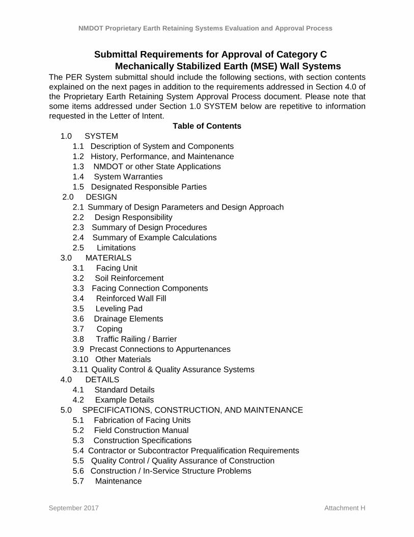
Submittal Requirements for Approval of Category C Mechanically Stabilized Earth (MSE) Wall Systems
The PER System submittal should include the following sections, with section contents explained on the next pages in addition to the requirements addressed in Section 4.0 of the Proprietary Earth Retaining System Approval Process document. Please note that some items addressed under Section 1.0 SYSTEM below are repetitive to information requested in the Letter of Intent.
Table of Contents 1.0 SYSTEM 1.1 Description of System and Components 1.2 History, Performance, and Maintenance 1.3 NMDOT or other State Applications 1.4 System Warranties 1.5 Designated Responsible Parties 2.0 DESIGN 2.1 Summary of Design Parameters and Design Approach 2.2 Design Responsibility 2.3 Summary of Design Procedures 2.4 Summary of Example Calculations 2.5 Limitations 3.0 MATERIALS 3.1 Facing Unit 3.2 Soil Reinforcement 3.3 Facing Connection Components 3.4 Reinforced Wall Fill 3.5 Leveling Pad 3.6 Drainage Elements 3.7 Coping 3.8 Traffic Railing / Barrier 3.9 Precast Connections to Appurtenances 3.10 Other Materials 3.11 Quality Control & Quality Assurance Systems 4.0 DETAILS 4.1 Standard Details 4.2 Example Details 5.0 SPECIFICATIONS, CONSTRUCTION, AND MAINTENANCE 5.1 Fabrication of Facing Units 5.2 Field Construction Manual 5.3 Construction Specifications 5.4 Contractor or Subcontractor Prequalification Requirements 5.5 Quality Control / Quality Assurance of Construction 5.6 Construction / In-Service Structure Problems 5.7 Maintenance
NMDOT Proprietary Earth Retaining Systems Evaluation and Approval Process
September 2017 Attachment H
1.0 SYSTEM 1.1 Description of System and Components
• Summarize what the system consists of and what is not included, but necessary, to construct the wall.
• Summarize external materials and variables which will influence the design, construction and performance of the system.
• List each component of the system. • List material requirements for each component.
1.2 History, Performance, and Maintenance
• Summarize the history of development and application of the system. • Summarize refinements made to the system, since inception. • Summarize performance (with photos, where available) of completed
structures, including: ○ Oldest ○ Tallest ○ Projects experiencing maximum measured settlement (total and
differential) ○ Measurements of lateral movement / tilt ○ Demonstrated aesthetics ○ Project photos ○ Maintenance and performance history, including improvements
that have been made based on the experience with the system
• Summarize any incidents where approval was revoked by a government agency for the system or any component of the system during the past five years. List these incidents if any, and describe the relationship between the rejected or revoked product component and the system being evaluated in this report. Where applicable, include a description of any predecessor product component or system.
1.3 NMDOT or other State Applications • Summarize the history of application of the system. • Summarize the history of application of the system on NMDOT
projects. • Summarize design issues specific to NMDOT applications. • Summarize construction issues specific to NMDOT applications. • Provide a list of non-NMDOT users, including a contact person for
each user with their telephone number, email address and a summary of all projects where the system has been used.
1.4 System Warranties Provide a copy of all system warranties
NMDOT Proprietary Earth Retaining Systems Evaluation and Approval Process
• System performance • Material performance • Project-specific design and construction details
2.0 DESIGN
2.1 Summary of Design Parameters and Design Approach Provide a summary of the following, and note applicable standard and / or test method used to quantify value:
• Nominal strength of soil reinforcement element(s) • Long-term factored strength of soil reinforcement element(s) • Direct shear interaction coefficient • Normalized pullout resistance factors, F* and α • Galvanization or other protective coating requirements and thickness
2.2 Design Responsibility
• State designated responsible party for project-specific design. • Detail the system designer's Quality Control / Quality Assurance
programs for project designs. • List those items of a project design that you understand, or assume,
are the responsibility of NMDOT. 2.3 Summary of Design Procedures
• Transportation Officials (AASHTO) LRFD Bridge Design Specifications, along with theoretical or empirical information which support such deviations.
• Summarize when and how external stability (global stability, bearing resistance, sliding resistance, and limiting eccentricity) is assessed.
• Summarize when and how internal stability is assessed. • Summarize seismic design considerations. • Detail design modification for tiered structures. • Detail design modification for acute corners. • Detail design to overcome obstructions (e.g., drainage structures, deep
foundations, etc.) in reinforced zones. 2.4 Summary of Example Calculations
• Provide detailed calculations for the external stability of the wall. Provide detailed calculations for the long-term factored tensile strength of the soil reinforcement and at the connection of the soil reinforcement to the facing units. Note any deviation from the most current AASHTO LRFD Bridge Design Specifications.
• Provide detailed calculations for soil reinforcement pullout resistance.
NMDOT Proprietary Earth Retaining Systems Evaluation and Approval Process
September 2017 Attachment H
• Provide detailed calculations for reinforcing steel in facing units, as applicable.
2.5 Limitations List all design limitations, including seismic loading; environmental restraints; wall height; external loading; foundation bearing resistance; settlement; differential settlement; and others.
3.0 MATERIALS
Provide material specifications describing the material type, quality, certifications, lab and field testing, and acceptance and rejection criteria, along with support information (and where noted, a sample of the material) for each of the following material items. Include representative test results (lab and field) clearly referencing the date, source, and method of test, and where required, the method and detailed explanation of interpretation and extrapolation. Note the source of the supplied information, include a listing of facilities normally used for testing (e.g., in-house and independent). Clearly identify the materials listed below that do not apply to the product being submitted.
3.1 Facing Unit This section should include the following: For wet-cast, steel reinforced panels or Large Block unreinforced masonry units
• Standard dimensions and tolerances • Reinforcing steel details, if applicable • Joint sizes and details • Concrete strength (minimum) • Wet cast concrete % air (range) • Freeze thaw durability • Bearing pads (joints) • Spacers (pins, etc.) • Joint filter requirements: geotextile or graded granular • Aesthetic choices (texture, relief, color, graffiti treatment) • Other facing materials
For Modular Block – dry-cast, unreinforced masonry units
• Standard dimensions and tolerances • Thickness at front face • Joint sizes and details • Concrete strength (minimum) • Dry cast concrete density (minimum or range)
NMDOT Proprietary Earth Retaining Systems Evaluation and Approval Process
September 2017 Attachment H
Moisture absorption (percent and by weight) • Salt scaling • Freeze thaw durability • Facing unit to facing unit shear resistance • Bearing pads • Spacers, pins, etc. • Joint filler requirements: geotextile or graded granular • Maximum recommended vertical joint opening • Aesthetic choices (textures, relief, color, graffiti treatment) • Other facing materials
3.2 Soil Reinforcement For Metallic soil reinforcement
• Manufacturing sizes, tolerances and lengths • Ultimate and yield strength of steel • Minimum galvanization thickness for 100 year design life • Sacrificial steel thicknesses for 100 year design life • Pullout interaction coefficients for range of backfill For Geosynthetic Soil Reinforcement
• Polymer resin and grade • High Density Polyethylene (HDPE): resin type, class, grade, and
category • Polypropylene (PP): resin type, class, grade, and category • Polyester (PET): minimum intrinsic viscosity correlated to number
average molecular weight and maximum carboxyl end groups • Mass per unit area • Post-consumer recycled material, if any • Nominal strength minimum average roll value and coefficient of
variation for nominal strength • QC strength (e.g., single rib, grab or strip) minimum average roll value • Creep reduction factors for 100 year design life, including effect of
temperature (20 C to 40 C) • Durability reduction factor (chemical, hydrolysis, oxidative) for 100 year
design life • Additional durability reduction factor for high biologically active
environments • Installation damage reduction factor for range of backfill (e.g., sand,
sandy gravel, gravel, coarse gravel) for allowable gradation criteria • Junction strength (geogrids) for quality control • Pullout interaction coefficients/pullout resistance factors for range of
NMDOT Proprietary Earth Retaining Systems Evaluation and Approval Process
September 2017 Attachment H
• UV inhibitors, coatings, etc. • UV resistance
3.3 Facing Connection Components
• Mode (e.g., structural, frictional, or combined) • Connection strength as a % of reinforcement strength at various
confining pressures for each reinforcement product and connection type submitted
• Composition of devices, dimensions, tolerances • Full scale connection test method / results
3.4 Reinforced Wall Fill • Soil classification • Gradation range • Unit weight (design and representative measured) • Friction angle (design and representative measured)
3.5 Leveling Pad • Size requirements • Concrete strength, minimum
3.6 Drainage Elements
• Weep holes • Drainage fill classification and gradation range • Surface drainage components • Subsurface drainage components
3.7 Coping • Precast concrete coping • Cast-in-place coping • Precast and cast-in-place combination • Installation/attachment method and details
3.8 Traffic Railing / Barrier 3.9 Precast Connections to Appurtenances 3.10 Other Materials
• Corner elements • Slip-joint elements
NMDOT Proprietary Earth Retaining Systems Evaluation and Approval Process
September 2017 Attachment H
3.11 Quality Control & Quality Assurance Systems
• Material suppliers ○ Metallic soil reinforcement ○ Geosynthetic soil reinforcement ○ Concrete products ○ Foundation or leveling pad ○ Connectors between facing units ○ Reinforced Wall fill
• Fabricator(s) • Test facilities (internal and external)
4.0 DETAILS
4.1 Standard Details Provide detailed drawings of the following standard details (electronic copy in pdf and AutoCAD/CIVIL 3D 2013 as required per:
http://www.dot.state.nm/content/nmdot/en/CADD.html or later version
• Leveling pad • Facing unit reinforcing steel and connection inserts • Erection details of facing units including temporary bracing, batter, joint
spacing, etc. • Connection • Top of wall coping • Top of wall traffic barrier • Bottom of wall traffic barrier • Construction of cast-in-place traffic barriers • Joint drainage details • Weep holes • Subsurface drainage • Subsurface drain outlets • Slip joint detail • End of wall • Connection to appurtenances (e.g., box inlets and large obstructions) • Fill placement procedures at soil reinforcement elevation • Architectural face finish options
4.2 Example Details Provide detailed drawings illustrating typical examples of the following details:
• Stepping of leveling pad with existing and final grades
NMDOT Proprietary Earth Retaining Systems Evaluation and Approval Process
September 2017 Attachment H
• Stepping of top of wall with final grade • Placement of soil reinforcement around steel piles • Placement of soil reinforcement around drop inlet structures • Placement of soil reinforcement around pipe penetrations
5.0 SPECIFICATIONS, CONSTRUCTION, AND MAINTENANCE
Provide the following information related to construction of the system: 5.1 Fabrication of Facing Units
• Curing times • Form removal • Concrete surface finish requirements
5.2 Field Construction Manual Provide a documented field construction manual describing in detail, with illustrations as necessary, the step-by-step construction sequence, including requirements for: • Foundation preparation • Special tools required • Leveling pad • Facing erection • Facing batter for alignment • Steps to maintain horizontal and vertical alignment • Reinforced wall fill and backfill placement / compaction • Erosion mitigation • All equipment requirements
5.3 Construction Specifications Include sample construction specifications that address:
• Materials requirements • Field sampling, testing, and acceptance / rejection requirements • Installation requirements • Maintenance requirements • Aesthetics compliance, including texture, color, graffiti treatment, and
durability of aesthetic features 5.4 Contractor or Subcontractor Prequalification Requirements
List any contractor or subcontractor prequalification requirements 5.5 Quality Control / Quality Assurance of Construction
Detail the quality control and quality assurance measurements required during construction to assure consistency in meeting performance requirements, and responsible parties for each.
NMDOT Proprietary Earth Retaining Systems Evaluation and Approval Process
September 2017 Attachment H
5.6 Construction / In-Service Structure Problems Provide case histories of structures where problems have been encountered, including an explanation of the problems and methods of repair.
5.7 Maintenance Provide a listing of maintenance requirements to maintain performance and repair damage. If available, provide a maintenance manual