The International Authority on Air System Components AIR MOVEMENT AND CONTROL ASSOCIATION INTERNATIONAL, INC. ANSI/AMCA Standard 250-05 Laboratory Methods of Testing Jet Tunnel Fans for Performance An American National Standard Approved by ANSI on August 31, 2005
Transcript
The International Authority on Air System Components
AIR MOVEMENT AND CONTROLASSOCIATION INTERNATIONAL, INC.
ANSI/AMCAStandard 250-05
Laboratory Methods of TestingJet Tunnel Fans for Performance
An American National StandardApproved by ANSI on August 31, 2005
ANSI/AMCA STANDARD 250-05
Laboratory Methods of Testing
Jet Tunnel Fans for Performance
Air Movement and Control Association International, Inc.
All rights reserved. Reproduction or translation of any part of this work beyond that permitted by Sections 107 and108 of the United States Copyright Act without the permission of the copyright owner is unlawful. Requests forpermission or further information should be addressed to the Chief Staff Executive, Air Movement and ControlAssociation International, Inc. at 30 West University Drive, Arlington Heights, IL 60004-1893 U.S.A.
Authority
ANSI/AMCA Standard 250-05 was adopted by the membership of the Air Movement and Control AssociationInternational, Inc. on 14 January 2001. It was approved by ANSI as an American National Standard on 31 August2005.
AMCA 250 Review Committee
Tony Quinn, Chair Woods Division, American Fan Co.
Roger Lichtenwald American Warming & Ventilating
Ralph Susey New Philadelphia Fan Company
John Knapp Ruskin Manufacturing
Mike Wiltfong Ruskin Manufacturing
Robert Smith TLT-Babcock, Inc.
Paul R. Saxon AMCA Staff
Foreword
This standard was developed in response to the need for a standard method of testing jet fans, sometimes calledimpulse fans, which have seen increasing use in the United States. The test procedures outlined in this standardare in harmony with those found in ISO 13350. It is believed that ANSI/AMCA 250 will be of great benefit topurchaser and manufacturer alike.
Introduction
The need for adequate ventilation to maintain or improve the quality of air in vehicular tunnels is self-evident. Onemeans of achieving such ventilation is through the use of fans located above the traffic pattern and spaced atintervals along the length of a tunnel. These fans produce a jet (or impulse) of air that induces airflow through theentire tunnel. Secondarily, this means of achieving airflow is also useful in smoke evacuation.
Disclaimer
AMCA uses its best efforts to produce standards for the benefit of the industry and the public in light of availableinformation and accepted industry practices. However, AMCA does not guarantee, certify or assure the safety orperformance of any products, components or systems tested, designed, installed or operated in accordance withAMCA standards or that any tests conducted under its standards will be non-hazardous or free from risk.
Objections to AMCA Standards and Certifications Programs
Air Movement and Control Association International, Inc. will consider and decide all written complaints regardingits standards, certification programs, or interpretations thereof. For information on procedures for submitting andhandling complaints, write to:
Air Movement and Control Association International30 West University DriveArlington Heights, IL 60004-1893 U.S.A.
or
AMCA International, Incorporatedc/o Federation of Environmental Trade Associations2 Waltham Court, Milley Lane, Hare HatchReading, BerkshireRG10 9TH United Kingdom
This standard deals with the determination of thosetechnical characteristics needed to describe allaspects of the performance of jet tunnel fans. It doesnot cover those fans designed for ducted applicationsnor those designed solely for air circulation, e.g.,ceiling fans and table fans.
The test procedures described in this standard relateto laboratory conditions. The measurement ofperformance under in-situ conditions is not included.
The parties to a test for guarantee purposes mayagree on exceptions to this standard in writing prior tothe test. However, only tests that do not violate anymandatory requirements of this standard shall bedesignated as tests conducted in accordance withthis standard.
2. Normative References
The following standards contain provisions that,through specific reference in this text, constituteprovisions of this American National Standard. At thetime of publication the editions indicated were valid.All standards are subject to revision, and parties toagreements based on this American NationalStandard are encouraged to investigate thepossibility of applying the most recent editions of thestandards listed below.
AMCA 300-96, Reverberant Room Method for SoundTesting of Fans, Air Movement and ControlAssociation International, Inc., Arlington Heights, IL,USA.
ANSI S2.19-1999 (R2004), Mechanical Vibrations -Balance Quality Requirements of Rigid Motors - Part1: Determination of Possible Unbalance, IncludingMarine Applications, American National StandardsInstitute, New York, NY, USA.
ANSI/AMCA 204-96 Balance Quality and VibrationLevels for Fans, Air Movement and ControlAssociation International, Arlington Heights, ILU.S.A., 1998
ANSI/AMCA 210-99 Laboratory Methods of TestingFans for Aerodynamic Performance Rating, AirMovement and Control Association International,Arlington Heights, IL U.S.A., 2000
ANSI/NEMA MG 1-2003, Motors and Generators,National Electrical Manufacturers Association,Rosslyn, VA, USA.
ISO 5801:1997(E), Industrial Fans - PerformanceTesting Using Standardized Airways, InternationalOrganization for Standardization, Geneva,Switzerland, 1996
3. Definitions and Symbols
3.1 Definitions
For the purposes of this standard, the followingdefinitions apply:
3.1.1 Air. A mixture of various gases forming theearth’s atmosphere and commonly used to denoteany gaseous medium measured, moved or controlledin a HVAC system.
3.1.2 Standard air. Air with a density of 1.2 kg/m3
(0.75 lbm/ft3), a specific heat ratio of 1.4, a viscosityof 1.819 × 10⁻⁵ Pa•s (1.222 × 10⁻⁵ lbm/ft-sec) and anabsolute pressure of 101.325 kPa (408.0 in. wg). Airat 20°C (68°F), 50% relative humidity, and 101.325kPa (29.92 in. Hg) has these properties,approximately.
3.1.3 Absolute pressure. Pressure above a perfectvacuum; the sum of gauge pressure and atmosphericpressure. The value is always positive.
3.1.4 Barometric pressure. The absolute pressureexerted by the atmosphere at a location ofmeasurement.
3.1.5 Dry-bulb temperature. Air temperaturemeasured by a temperature-sensing device withoutmodifications to compensate for the effect ofhumidity.
3.1.6 Static pressure at a point. That portion of airpressure that exists by virtue of the degree ofcompression only. If expressed as gauge pressure, itmay be negative or positive.
3.1.7 Volume airflow rate. The volume of air thatpasses through a given area in unit time.
AMCA INTERNATIONAL, INC. ANSI/AMCA 250-05
Actual Cubic Meters per Second (actual m3/s), orActual Cubic Feet per Minute (acfm): The actualvolume airflow rate at any point in an air system, atthe existing density at the plane passing through thepoint of measurement.
3.1.8 Average air velocity. The volume airflow at aplane divided by the cross-sectional area of thatplane.
3.1.9 Fan dynamic pressure. The effective dynamicpressure at the fan outlet calculated from theeffective fan outlet velocity and the inlet density. It isrepresentative of the dynamic component of the fanoutput. The effective dynamic pressure varies fromthe average dynamic pressure as the formerexcludes the energy flux due to departures from theuniform axial velocity distribution.
3.1.10 Fan outlet area. The gross inside areameasured at the plane(s) of the outlet openings.
1) If the silencer centerbody reaches the outletplane of the fan then the "fan outlet area" isdefined as the annulus area at the fan outletplane as shown in Figure 1A.
2) If the fan has a silencer without centerbody,Figure 1B, the outlet area will be close to thecross-sectional area inside the silencer in orderto clear any exit bellmouth form.
3) For a fan without a silencer, Figure 1C, the outletarea will approach the annulus area between thecasing and the motor but with some increase, asdefined in the diagram, for the distance betweenthe motor and the outlet.
4) Where the motor is on the upstream side, Figure1C is applied to the impeller hub rather than themotor - as illustrated.
3.1.11 Effective fan outlet velocity. Calculated airvelocity based on fan thrust, inlet air density and fanoutlet area.
3.1.12 Fan outlet velocity. Average velocity of airemerging from an outlet measured in the plane of theoutlet.
3.1.13 Air power. Power output which is the productof the inlet volume airflow and the fan dynamicpressure.
3.1.14 Impeller power. The mechanical powersupplied to the fan impeller.
3.1.15 Motor input power. The electrical powersupplied to the terminals of an electric motor drive.
3.1.16 Rotational speed. The rotational speed of animpeller. If a fan has more than one impeller, fanspeeds are the rotative speeds of each impeller.
3.1.17 Mean blade speed. The tangential velocity at1/√2 (or 0.7071) times the blade height betweenimpeller hub and tip.
3.1.18 Thrust. The force exerted by a fan in aspecific direction.
3.1.19 Fan efficiency. Ratio of the air power to theimpeller power, expressed as a percentage.
3.1.20 Overall efficiency. Ratio of the air power tothe motor input power, expressed as a percentage.
Figure 1 - Effective Fan Outlet Area
ANSI/AMCA 250-05
2
ANSI/AMCA 250-05
3.1.21 Thrust/power ratio. Ratio of the thrust toimpeller power.
Note: An alternative definition of thrust efficiency isdefined as thrust divided by the motor input power.This results in a lower figure as the motor losses arealso included.
3.1.22 Fan. A device that utilizes a power drivenrotating impeller for moving air or gases. The internalenergy (enthalpy) increase imparted by a fan to a gasdoes not exceed 25 kJ/kg (10.75 BTU/lbm).
3.1.23 Jet tunnel fan. A fan used for producing a jetof air in a space and unconnected to any ducting.Typical function is to add momentum to the air withina duct or tunnel.
3.1.24 Fan guard. A screen or other device to preventingestion of objects at the inlet or outlet of a fan.
Note: Guards can have a marked effect on the thrustperformance and sound level. Where they arespecified, it shall be made quite clear between thesupplier and his customer whether the performanceincludes the effect of the guards.
3.1.25 Chamber. An airway in which the air velocityis small compared to that at the fan inlet or outlet.
3.1.26 Test enclosure. A room, or other space usedfor the purposes of testing.
3.1.27 Sound power level, Lw. Acoustic power ratingfrom a sound source measured in decibels and equalto 10 times the logarithm (base 10) of the acousticpower in watts with reference to 10 ×10-12 watts.
3.1.28 Sound pressure level, Lp. The acousticpressure at a point in space where the microphone orlistener’s ear is situated. It is defined as 20 times thelogarithm (base 10) of the sound pressure fluctuationwith reference to 20 μPa.
3.1.29 Frequency range of interest. The frequencyrange including the octave bands with centerfrequencies between 63 Hz and 8 kHz, and the one-third octave bands with center frequencies between50 Hz and 10 kHz.
3.1.30 Impeller balance grade. The impellerbalance specification in accordance with the methoddetailed in ANSI S2.19 and to the grade specified inANSI/AMCA 204.
3.1.31 Fan vibration velocity. The filtered vibrationvelocity in the frequency range 10 Hz through 10 kHzmeasured in accordance with this standard.
3.1.32 Shall and should. In AMCA standards, theword “shall” is understood to be normative; the word“should” as advisory.
3.2 Symbols
See Table 1 for a list of symbols.
4. Characteristics to be Measured
4.1 General
In order for a jet-type tunnel fan to be correctlyapplied and give satisfactory performance andreliability in service, it is necessary to determine anumber of technical performance characteristics inaddition to knowing the more obvious mechanicalfeatures such as weight and overall installationdimensions.
4.2 Volume airflow rate
Volume airflow rate need only be measured ifrequired for contractual reasons. The effective outletvelocity, not the volumetric airflow rate, is used toevaluate the optimum number, size and spacing of jetfans in a tunnel. Higher velocities reduce thrustefficiency but the effect of tunnel air velocity on thrustis reduced.
4.3 Thrust
Friction on the tunnel walls, inlet and outlet lossesand, sometimes, traffic drag combined with gradientsand wind effects at tunnel portals, result in a pressuredrop through the tunnel. The pressure drop ismatched by the sum of the pressure increases by thejet fans due to the momentum transfer between thefan discharge airflow and the airflow in the tunnel. Asit is impossible to measure the momentum of the fandischarge airflow, and the rate of change ofmomentum is equal and opposite to the thrust, thrustis measured instead.
The process of providing additional momentum to thetunnel air helps to maintain air quality.
4.4 Input power
In order to calculate the cost of operating the jettunnel fans (there may be a substantial number) in atunnel, it is necessary to know the input power to thefan motor.
4.5 Sound power level
Sound levels, usually at inlet and outlet, areestablished in order to ensure that the jet fan and
3
Table 1 - Symbols
SYMBOL DESCRIPTION SI Units I-P Units
Aeff Area of fan inlet or outlet m2 ft2
D Fan diameter mm in.d3 Length of upstream chamber side m ftΔP Differential pressure across a flow measuring device Pa in. wgG Impeller balance grade ANSI/AMCA 204 dimensionlessLpb Background sound pressure level dB dBLp(m) Recorded sound power level of fan and room back- dB dB
ground as measured over the normal mic. pathLp(r) Recorded sound pressure level of RSS and room dB dB
background as measured over the normal mic. pathLw Sound power level, re 1 pW dB dBLw(r) Sound power level of the RSS dB dBLw1 Sound power level (forward) dB dBLw2 Sound power level (reverse) dB dBLp Sound pressure level dB dBN Impeller rotational speed rpm rpmPa Atmospheric pressure in test enclosure Pa in. Hgpd Fan dynamic pressure Pa in. wgPE Motor input power W hpPF Fan air power W hpPR Impeller power W hpqm Mass airflow kg/s lbm/s
qv Volume airflow m3/s cfmrT Thrust/power ratio N/kW lbf/Hpta Atmospheric temperature in test enclosure (dry-bulb) °C °FTc Calculated thrust N lbfTm Measured thrust N lbfum Mean blade speed (see definition 3.1.17) m/s ft/minvt Mean through airflow velocity in a m/s ft/min
tunnel at a specified sectionveff Effective fan outlet air velocity m/s ft/minV1 Fan vibration velocity at upstream mm/s in./s
measuring position - rms valueV2 Fan vibration velocity at downstream mm/s in./s
measuring position - rms valueηr Fan efficiency % %ηe Overall efficiency % %
ρa Inlet air density taken as equal to the kg/m3 lbm/ft3
air density in the test enclosure
4
ANSI/AMCA 250-05
5
ANSI/AMCA 250-05
silencer combination is optimized to match the tunnelsound level requirements.
4.6 Vibration velocity
For reasons of safety, reliability and maintainability, itis essential that a realistic vibration velocity isspecified and recorded on tunnel fans. These shall bemeasured at the support points in accordance withANSI/AMCA 204.
5. Instrumentation and Measurements
5.1 Volume airflow rate
5.1.1 Instruments for the measurement of
pressure. Manometers for the measurement ofdifferential pressure, and barometers for themeasurement of atmospheric pressure in the testenclosure, shall comply with the requirements ofANSI/AMCA 210 or ISO 5801.
5.1.2 Instruments for the measurement of
temperature. Thermometer(s) shall comply with therequirements of ANSI/AMCA 210 (ISO 5801).
5.2 Thrust
5.2.1 Force balance systems. By the use ofcalibrated weights, force balance systems shallpermit the determination of force or thrust with anallowable uncertainty of no greater than ±1%.
5.2.2 Force transducers. By the use of calibratedweights, force transducers shall permit thedetermination of thrust with an allowable uncertaintyno greater than ±1%.
5.2.3 Dimensions and areas. The measurement ofdimensions and the determination of areas shall be inaccordance with ANSI/AMCA 210 or ISO 5801.
5.3 Input power
Determination of the power input to the electric motoror to the impeller shall be carried out in accordancewith ANSI/AMCA 210 or ISO 5801.
5.4 Impeller rotational speed
Impeller rotational speed shall be determined inaccordance with ANSI/AMCA 210 or ISO 5801.
5.5 Sound level
The sound level measuring system includingmicrophones, windshields, cables, amplifiers andfrequency analyzer shall be in accordance with the
requirements given in ANSI/AMCA 300.
5.6 Vibration velocity
Instruments to measure rms vibration velocity shallbe used to record fan vibration velocities. Theseshall be in accordance with ANSI/AMCA 204.
6. Determination of Airflow Rate
6.1 General
There are three methods available for thedetermination of airflow rate. The most convenientuses a venturi nozzle or conical inlet, connectedupstream of the jet tunnel fan, as the airflowmeasuring device. The second makes use of anupstream chamber test configuration. In this case abooster fan forms part of the test setup enabling thefan's operating point to be simulated correctly. Thethird method uses a Pitot traverse at the jet fan inlet.
It should be noted that the airflow through a jet fanhas no direct relationship with the airflow through atunnel.
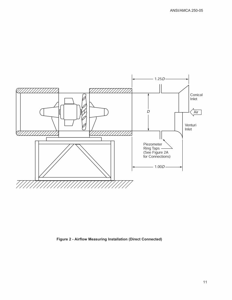
6.2 Direct connected airflow measuring device
The airflow measuring device shall be connected bysuitable means to the fan inlet as illustrated on Figure2. Details of the venturi nozzle shall comply withANSI/AMCA 210, Figure 4. Details of the conical inletshall comply with ISO 5801, Figure 21. For thepurpose of airflow rate determination in accordancewith this standard, an anti-swirl device is not required.
Airflow rate for the venturi nozzle is calculated inaccordance with ANSI/AMCA 210, Section 8. Airflowrate for a conical inlet is calculated in accordancewith ISO 5801 clause 24.
6.3 Upstream chamber method
Installation of the fan in the chamber is illustrated inFigure 3. This arrangement simulates a free inlet,free outlet installation. Upstream sections of the testassembly shall be in accordance with ANSI/AMCA210 or ISO 5801.
A venturi nozzle, quadrant inlet nozzle, or conicalinlet can be used to determine airflow rate inaccordance with ISO 5801, clauses 22, 24, and 25.Multiple nozzles may be used in accordance withANSI/AMCA 210, Figure 14 or 15.
In order to establish the correct operating point, withno adverse pressure across the fan, a test systembooster fan shall be controlled such that:
ANSI/AMCA 250-05
Ps3 = Ps2 = 0
Where Ps3 is the static pressure in the fan chamberand Ps2 is the static pressure at the fan outlet.
If it is not possible to control the booster accurately, itmay be necessary to measure the airflow at morethan one operating point.
6.4 Upstream pitot traverse method
For this method, the airflow rate should bedetermined in accordance with ANSI/AMCA 210 (ISO5801).
7. Determination of Thrust
7.1 General
There are two basic configurations available for thedetermination of fan thrust; suspended configurationand supported configuration. In addition to the needto measure force accurately, the first method requiresthat the suspension elements be kept preciselyvertical and parallel with a vertical plane(s) passingthrough the fan axis, while the second methodrequires accurate construction and leveling of thesupport assembly. In either case, thrust shall bedetermined by the use of calibrated weights, springbalance or force transducer.
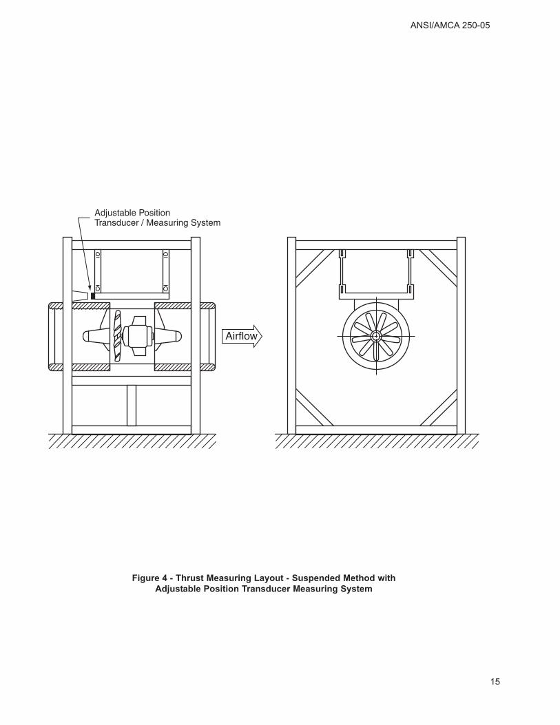
7.2 Suspended configuration
Figure 4 shows a typical arrangement of asuspended configuration. The fan is suspended froma framework or gantry with the suspension elementsat least one fan diameter long. The frame shouldallow free airflow, particularly at the fan inlet. Belowor surrounding the fan, is a rigid framework whichserves a threefold function:
a) provides the reference point for the fan testassembly under static conditions
b) provides support for a pulley system to takecalibrated weights or a spring balance
c) provides a reaction point for a force transducer
Under operating conditions, the measuring systemloads are adjusted to return the fan to the staticposition, to within ±2 mm (0.08 inches), and thusensure that the suspension elements are preciselyvertical. The thrust can then be measured directly.
Note: It should be noted that with the thrust/weightratios typical of a jet tunnel fan, it is doubtful whether
the desired accuracy of thrust measurement can beattained by other means such as measuring theangle of the suspension elements from the vertical orthe change in height between the fan switched offand operational, and calculating the thrust.
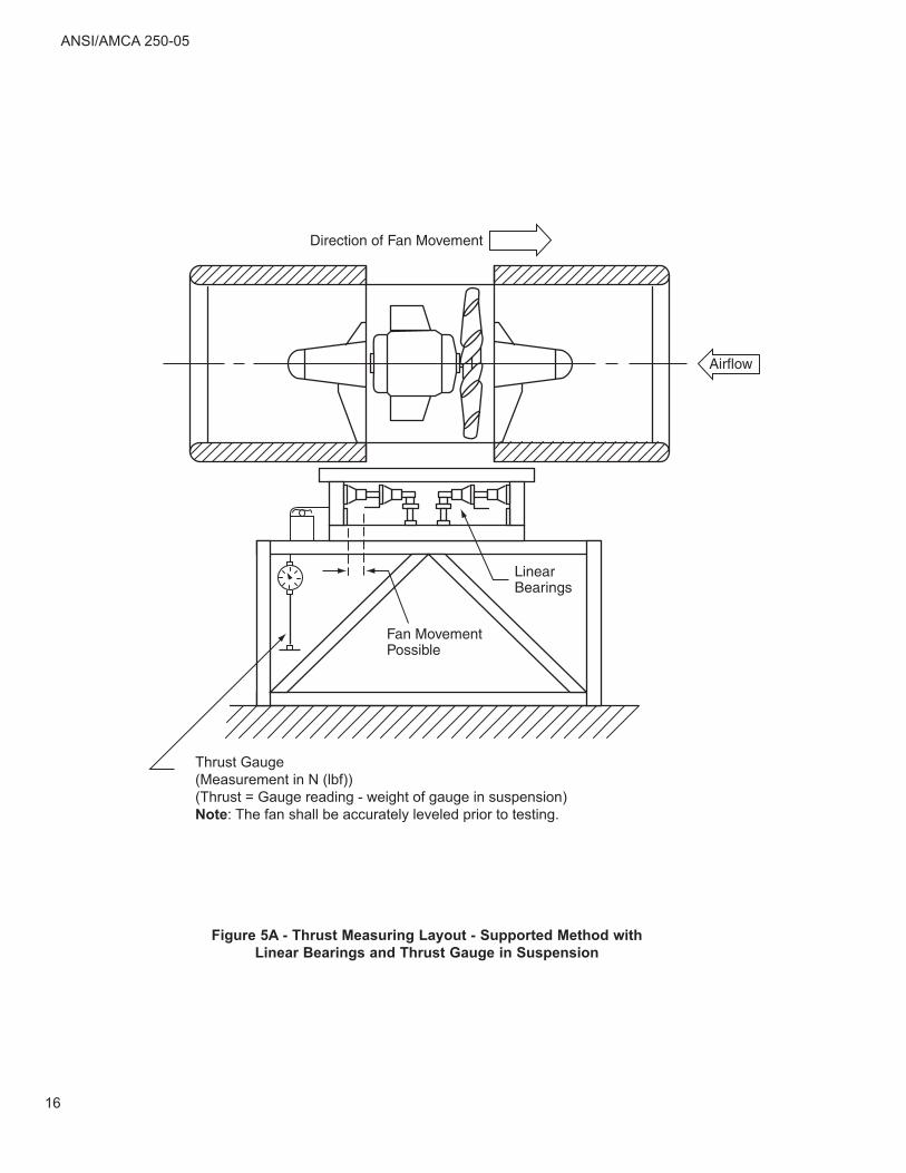
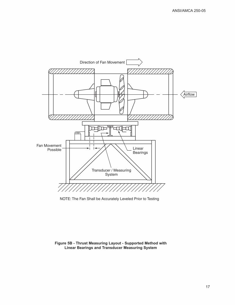
7.3 Supported configuration
Arrangements of the supported configuration areshown on Figures 5A, 5B and 5C. The fan issupported, via low friction linear bearings or leafsprings, on a rigid framework. The fan, to an extentlimited by stops, is free to move in either direction.Before commencing any tests, the assembly shall becarefully leveled in each direction, such that thesame effort is required to move the assembly alongthe axis of the fan, in either direction.
Under operating conditions, the measuring systemloads are adjusted to ensure the movement is notrestrained by the stops. Thrust can then be measureddirectly. In the case of the use of a force transducer,the fan can be allowed to abut the sensor directly.
7.4 Test procedures
To ensure that thrust is measured to the requiredaccuracy, steps shall be taken to minimize errors dueto setting up/rigging the test arrangement. Thoughcalibrated weights or spring balances are specified, ifa spring balance is employed to register thrust and itis supported via a pulley, its weight must beaccurately known and added to the measured thrust.
If a force transducer is being used to measure thrust,it shall be calibrated. For example, by using a pulleyand weight system, before each series of tests.
Where the supported method is being used,precautions shall be taken to ensure that the forcerequired to move the fan in either direction is thesame and that the assembly is therefore level.
Thrust readings shall be recorded when both thethrust and power input readings have stabilized, or atleast 10 minutes after start up.
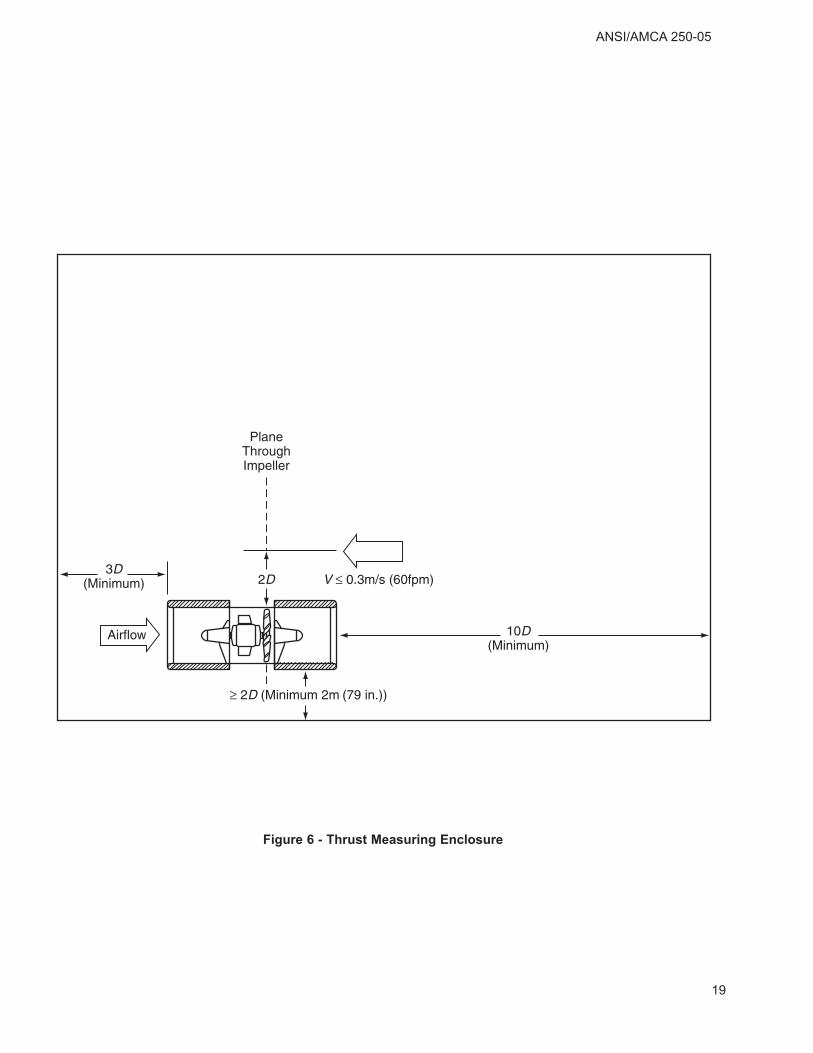
7.5 Test enclosure
Figure 6 shows the clearances required in the testenclosure.
8. Determination of Sound Level
8.1 General
Sound levels are measured by the semi-reverberantmethod. The method is essentially practical, and
6
ANSI/AMCA 250-05
apart from the sound measuring instrumentation,only a suitable enclosure and a calibrated ReferenceSound Source are required.
Since the fan has only one operating point (at zeroresistance), there are no complications that couldarise from the noise generated by the "loadingmeans." Similarly, since only open inlet or open outletsound levels are required, anechoic terminators areunnecessary.
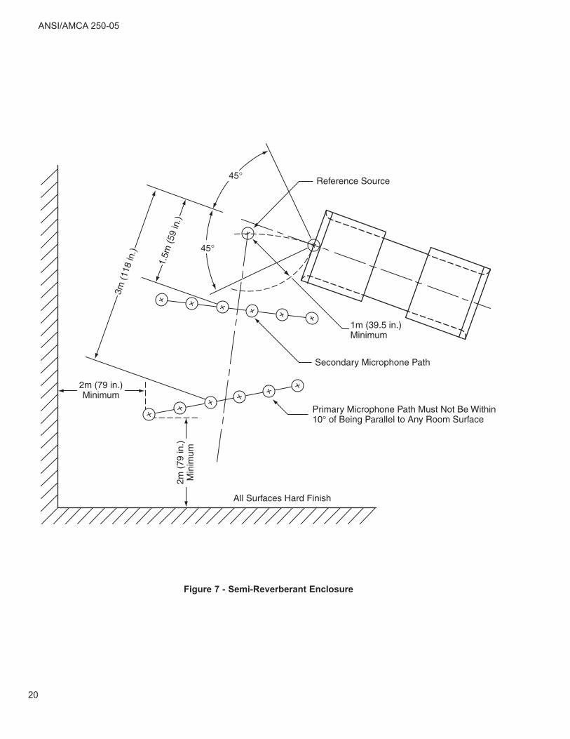
8.2 Test arrangement
Positioning of the fan, the calibrated ReferenceSound Source and the microphone paths are shownin Figure 7.
8.3 Enclosure suitability
A primary microphone path shall be located on an arcor straight line of length between 1.5 and 3 m (5 and10 ft) at a distance of not less than 2 m (79 in.) fromany major reflecting surface. No point on this pathshall be within 45° of the centerline of the fan soundsource, and the path itself shall not be within 10° ofbeing parallel to any room surface and shall belocated towards a corner of the room. The path shallbe located so that the microphone is not subjected toan air velocity in excess of 2 m/s (6.5 ft/sec); refer toFigure 7.
A Reference Sound Source (RSS) shall be locatedsuch that its acoustic center is the same distancefrom the mid point of the microphone path as thecenter of the fan sound source but not nearer to thelatter, or any major reflecting surface, than 1 m (3.25ft). The RSS shall meet the requirements ofANSI/AMCA 300 (also see Annex A). The RSS shallbe run at a speed within 2% of the speed at which itwas calibrated.
With the RSS operating, but with the test fan impellerstationary, readings of sound pressure level shall bemade in each octave band along the primarymicrophone path and the average value along thepath estimated. A secondary microphone path similarto the primary microphone and of the same lengthshall be established at a position half way betweenthe RSS and the mid point of the original microphonepath, and at right angles to the line joining them. Theaverage sound pressure level along this path in eachoctave band shall not be more than 3 dB above theaverage for the primary microphone path, bothvalues being corrected for background soundpressure level in accordance with Annex B.
8.4 Measurement procedure
Before conducting actual measurements, and withboth the test fan and the RSS inoperative, theaverage sound pressure level, in each octave bandshall be determined along the primary microphonepath. This shall be at least 6 dB in each octave bandlower than the average sound pressure levelmeasured from either the fan sound source or theRSS. Corrections for background sound pressurelevel should be made as recommended in Annex B.
With the RSS in operation, but with the test fanimpeller stationary, readings of sound pressure shallbe made in each octave band along the primarymicrophone path, and the average sound pressurelevel, Lp(r), shall be determined. With the RSSremoved and the test fan running, readings of soundpressure level shall be made and the average soundpressure level Lp(m), in each octave band, determined.The values of Lp(r) and Lp(m), are corrected, wherenecessary, as recommended in Annex B, and theopen inlet or open outlet sound power level of the fan,LW calculated, in each octave band, from:
LW = Lp(m) - Lp(r) + LW(r)
Where LW and LW(r) are in dB, and LW(r) is the soundpower level of the RSS.
For fans designed to provide thrust in one directiononly, the inlet sound power level, LW1, shall bequoted. Where the fan is designed to operate ineither direction, LW1 shall be quoted for the forwarddirection together with a correction to arrive at thevalue of LW2 for reverse operation.
9. Determination of Vibration Velocity
9.1 General
Because the jet tunnel fan, for practical purposes,has only one operating point as far as standardlaboratory tests are concerned, the arrangements fortesting vibration velocity can be simplified.
9.2 Test arrangement
Figure 8 illustrates the arrangement that shall beused for measuring vibration velocity. Tests shall betaken with the same jet tunnel fan configuration aswill be supplied to the customer. In other words,upstream and/or downstream silencers should befitted as appropriate. Where vibration isolators arespecified and vibration levels are required to bemeasured, the minimum static deflections given inTable 9.1 shall be used for the purpose of themeasurement.
7
Table 9.1 - Minimum Static Deflections
Unless agreed otherwise between client and supplier,the impeller of the fan unit shall be balanced to gradeG2.5 of ANSI S2.19 (ISO 1940) as recommended inANSI/AMCA 204 for jet tunnel fans. The electricmotor shall be supplied to the vibration level for themotor frame size in accordance with NEMA MG-1,Part 7 (IEC 34).
9.3 Test procedure
Unless agreed otherwise between client and supplier,vibration velocities shall be measured in accordancewith ANSI/AMCA 204. Owing to the axial symmetry ofthe jet fan and the simple two bearing assembly, it isonly necessary to record the vibration in the verticaldirection.
Two readings of vibration shall be recorded, one onthe upstream side and one on the downstream sidemounting bracket. The measured levels shall be:vertical vibration velocity in mm/s, r.m.s (in./s, r.m.s.)filtered to impeller rotational speed.
9.4 Acceptance vibration velocity
Table 9.2 - Acceptance Vibration Velocity
10. Presentation of Results
10.1 Product description
The test report shall include a product descriptionwhich, as a minimum, shall include the followinginformation:
a) Model reference
b) Size of fan
c) Impeller rotational speed
d) Motor output rating and frame size
e) Electrical supply data
f) High temperature operating capability
g) Overall dimensions
h) Mounting dimensions
i) Fan assembly weight
j) Accessories, e.g., guards, vibration isolators
k) Condition monitoring equipment.
10.2 Product performance
The performance of the product described in Section10.1, shall include the information described in thefollowing points a through e as a minimum. Byagreement with the client, the data may be providedfor "forward" and "reverse" operation.
It shall always be made clear which accessories werefitted when the performance tests were undertaken.
a) Thrust
b) Effective outlet air velocity; see Note 1
c) Motor input power
d) Maximum open inlet or open outlet soundpower level; see Note 2
e) Maximum upstream and downstream vibrationvelocity.
Note 1: the effective outlet air velocity veff is used tocalculate the correction factor, k, on the thrust due tothe mainstream tunnel air velocity, vt, in the tunnel.
Where:
k = (veff – vt) / veff
veff can best be defined as:
For the definition of Aeff, fan outlet area, see Section3.1.10.
v TAeff
m
eff a
=× ρ
Mounting Method Max. mm/s, Max. in./s,
Vibration isolatorsper Table 1
4.5 0.177
Hard Mounted 1.0 0.039
Impeller speed, rpmMinimum Static
Deflection
850 - 1000 15 mm (0.6 in.)
1100 - 1800 8 mm (0.3 in.)
2800 & above 2.5 mm (0.1 in.)
ANSI/AMCA 250-05
8
ANSI/AMCA 250-05
Note 2: It may be preferred, by prior agreement withthe client, to present sound level data in analternative form. For example, an A-weightedspherical sound pressure level at 10 or 3 m (33 or 10ft), 45° in free field. Also by agreement with the clientit shall be decided whether the sound level is givenas a single total figure or in each octave band.
Note 3: If required for contractual reasons, the airflowrate may be determined by one of the methods givenin ANSI/AMCA 210 or ISO 5801.
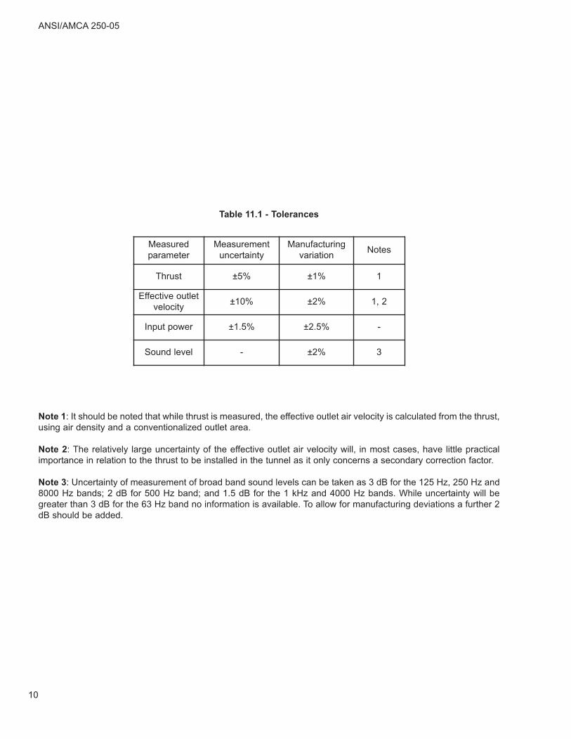
11. Tolerances and Conversion Rules
11.1 Tolerances
The performance quoted is the most probableperformance, not the minimum value. The tolerancevalues apply to jet tunnel fans operating withoutexternal resistance and as tested in accordance withthis standard.
As shown in Table 11.1, the tolerances are intendedto take account of measurement uncertainty andmanufacturing variations. When direct test resultsare not available, refer to Annex C.
11.2 Conversion rules
The conversion rules recommended in Annex Capply to fan assemblies with geometric similarity. Inthe case of jet tunnel fans this means similarity of thefollowing features:
Silencer lengths
Silencer pod geometry
Silencer bellmouth shape
Impeller hub to diameter ratio
Impeller spinner profile
Blade shape and solidity (number of blades)
Blade setting angle
Motor support design
Motor frame size
Blade tip clearance (smoke venting designs)
It is accepted that for practical reasons it is notreasonable for every configuration of fan to besubjected to a direct test. Also, perfect geometricsimilarity is not always readily achievable.Nonetheless, it is incumbent on the manufacturer toauthenticate any conversion rules used.
Application of conversion rules shall be limited asfollows: when calculating the performance of anotherfan from a direct test and allowing for some departurefrom geometric similarity:
Note 1: It should be noted that while thrust is measured, the effective outlet air velocity is calculated from the thrust,using air density and a conventionalized outlet area.
Note 2: The relatively large uncertainty of the effective outlet air velocity will, in most cases, have little practicalimportance in relation to the thrust to be installed in the tunnel as it only concerns a secondary correction factor.
Note 3: Uncertainty of measurement of broad band sound levels can be taken as 3 dB for the 125 Hz, 250 Hz and8000 Hz bands; 2 dB for 500 Hz band; and 1.5 dB for the 1 kHz and 4000 Hz bands. While uncertainty will begreater than 3 dB for the 63 Hz band no information is available. To allow for manufacturing deviations a further 2dB should be added.
Figure 4 - Thrust Measuring Layout - Suspended Method with
Adjustable Position Transducer Measuring System
ANSI/AMCA 250-05
15
Figure 5A - Thrust Measuring Layout - Supported Method with
Linear Bearings and Thrust Gauge in Suspension
Thrust Gauge(Measurement in N (lbf))(Thrust = Gauge reading - weight of gauge in suspension)Note: The fan shall be accurately leveled prior to testing.
ANSI/AMCA 250-05
16
Figure 5B - Thrust Measuring Layout - Supported Method with
Linear Bearings and Transducer Measuring System
ANSI/AMCA 250-05
17
Figure 5C - Thrust Measuring Layout - Supported Method with
Leaf Springs and Load Cell
ANSI/AMCA 250-05
18
Figure 6 - Thrust Measuring Enclosure
ANSI/AMCA 250-05
19
Figure 7 - Semi-Reverberant Enclosure
ANSI/AMCA 250-05
20
Figure 8 - Vibration Measuring Positions for Jet Tunnel Fans
ANSI/AMCA 250-05
21
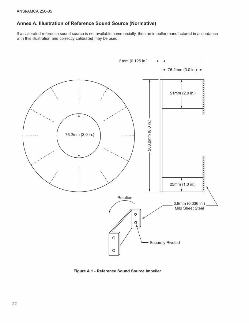
Figure A.1 - Reference Sound Source Impeller
Annex A. Illustration of Reference Sound Source (Normative)
If a calibrated reference sound source is not available commercially, then an impeller manufactured in accordancewith this illustration and correctly calibrated may be used.
ANSI/AMCA 250-05
22
Annex B. Combination of Sound Pressure Levels (Normative)
When the sound pressure level with the fan running exceeds the background sound pressure level with the fanstopped by 10 dB or more, no correction need be applied.
When the difference is less than 10 dB, corrections as given below should be applied.
Table B.1 - Background Correction
When the increase is less than 3 dB, measurements in general cease to have any significance.
dB increase in level produced by the fan
dB to be subtracted from themeasured value
3 3
4 - 5 2
6 - 9 1
10 or more 0
LL L
pc
pm pb
= −⎛
⎝⎜⎜
⎞
⎠⎟⎟
⎛
⎝⎜⎜
⎞
⎠⎟⎟
⎛
⎝⎜⎜
⎞
⎠⎟⎟
10 10 101010 10log
ANSI/AMCA 250-05
23
Annex C. Conversion Rules (Normative)
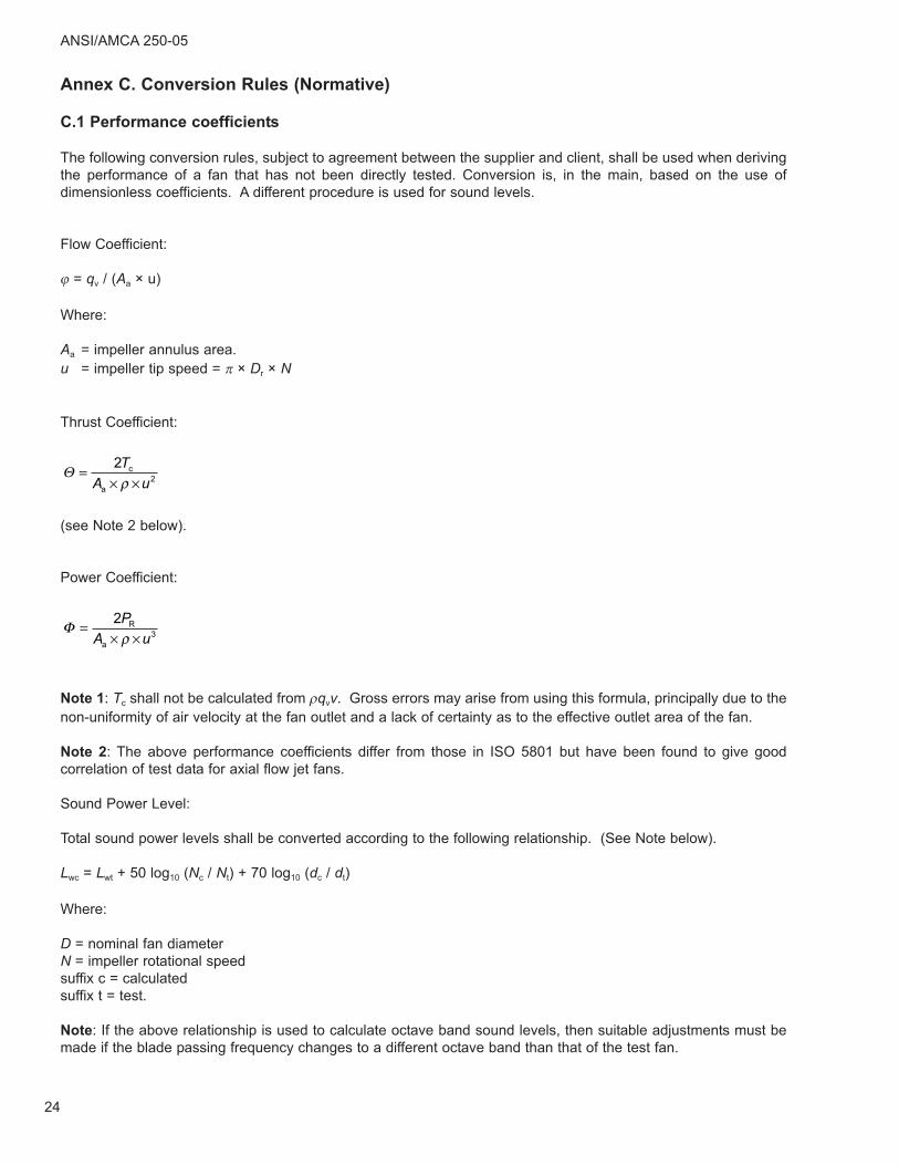
C.1 Performance coefficients
The following conversion rules, subject to agreement between the supplier and client, shall be used when derivingthe performance of a fan that has not been directly tested. Conversion is, in the main, based on the use ofdimensionless coefficients. A different procedure is used for sound levels.
Flow Coefficient:
ϕ = qv / (Aa × u)
Where:
Aa = impeller annulus area.u = impeller tip speed = π × Dr × N
Thrust Coefficient:
(see Note 2 below).
Power Coefficient:
Note 1: Tc shall not be calculated from ρqvv. Gross errors may arise from using this formula, principally due to thenon-uniformity of air velocity at the fan outlet and a lack of certainty as to the effective outlet area of the fan.
Note 2: The above performance coefficients differ from those in ISO 5801 but have been found to give goodcorrelation of test data for axial flow jet fans.
Sound Power Level:
Total sound power levels shall be converted according to the following relationship. (See Note below).
D = nominal fan diameterN = impeller rotational speedsuffix c = calculatedsuffix t = test.
Note: If the above relationship is used to calculate octave band sound levels, then suitable adjustments must bemade if the blade passing frequency changes to a different octave band than that of the test fan.
Φ =× ×2
3
PA u
R
a ρ
Θ =× ×2
2
TA u
c
a ρ
ANSI/AMCA 250-05
24
Annex D. Informative References
NEMA MG-1, 1993 (R1997), Motors and Generators, National Electrical Manufacturers Association, Rosslyln, VA,U.S.A., 1997
ANSI S2.19 (1989) Balance Quality of Rotating Rigid Bodies, American National Standards Institute, New York, NY,U.S.A., 1989
ISO 1940-1:1986, Mechanical Vibration -- Balance Quality Requirements of Rigid Rotors -- Part 1: Determinationof Permissible Residual Unbalance, International Organization for Standardization, Geneva, Switzerland, 1986
ANSI/AMCA 250-05
25
AIR MOVEMENT AND CONTROLASSOCIATION INTERNATIONAL, INC.
30 West University DriveArlington Heights, IL 60004-1893 U.S.A.
The Air Movement and control Association International, Inc. is a not-for-profit international association of the world’s manufacturers of related air system equipment primarily, but limited to: fans, louvers, dampers, air curtains, airflow measurement stations, acoustic attenuators, and other air system components for the industrial, commercial and residential markets.