NORME INTERNATIONALE CEI IEC INTERNATIONAL STANDARD 60044-5 PremiLre Ødition First edition 2004-04 Transformateurs de mesure Partie 5: Transformateurs condensateurs de tension Instrument transformers Part 5: Capacitor voltage transformers Pour prix, voir catalogue en vigueur For price, see current catalogue IEC 2004 Droits de reproduction rØservØs Copyright - all rights reserved Aucune partie de cette publication ne peut Œtre reproduite ni utilisØe sous quelque forme que ce soit et par aucun procØdØ, Ølectronique ou mØcanique, y compris la photocopie et les microfilms, sans l’accord Øcrit de l’Øditeur. No part of this publication may be reproduced or utilized in any form or by any means, electronic or mechanical, including photocopying and microfilm, without permission in writing from the publisher. International Electrotechnical Commission, 3, rue de VarembØ, PO Box 131, CH-1211 Geneva 20, Switzerland Telephone: +41 22 919 02 11 Telefax: +41 22 919 03 00 E-mail: [email protected]Web: www.iec.ch CODE PRIX PRICE CODE XB Commission Electrotechnique Internationale International Electrotechnical Commission Международная Электротехническая Комиссия
Transcript
NORME INTERNATIONALE
CEIIEC
INTERNATIONAL STANDARD
60044-5Première édition
First edition2004-04
Transformateurs de mesure
Partie 5: Transformateurs condensateurs de tension
Instrument transformers
Part 5: Capacitor voltage transformers
Pour prix, voir catalogue en vigueur For price, see current catalogue
IEC 2004 Droits de reproduction réservés Copyright - all rights reserved
Aucune partie de cette publication ne peut être reproduite ni utilisée sous quelque forme que ce soit et par aucun procédé, électronique ou mécanique, y compris la photocopie et les microfilms, sans l'accord écrit de l'éditeur.
No part of this publication may be reproduced or utilized in any form or by any means, electronic or mechanical, including photocopying and microfilm, without permission in writing from the publisher.
International Electrotechnical Commission, 3, rue de Varembé, PO Box 131, CH-1211 Geneva 20, SwitzerlandTelephone: +41 22 919 02 11 Telefax: +41 22 919 03 00 E-mail: [email protected] Web: www.iec.ch
CODE PRIX PRICE CODE XB Commission Electrotechnique Internationale
International Electrotechnical CommissionМеждународная Электротехническая Комиссия
3.1 General definitions................................................................................................. 17 3.2 Capacitor voltage divider definitions ....................................................................... 27 3.3 Electromagnetic unit definitions ............................................................................. 33 3.4 Carrier-frequency accessories definitions............................................................... 35
4 General requirements ..................................................................................................... 35 5 Service conditions...........................................................................................................35
5.1 Normal service conditions ...................................................................................... 35 5.2 Special service conditions...................................................................................... 39 5.3 System earthing..................................................................................................... 41
6 Ratings ........................................................................................................................... 41 6.1 Standard values of rated frequency........................................................................ 41 6.2 Standard values of rated voltages .......................................................................... 41 6.3 Standard values of rated output ............................................................................. 43 6.4 Standard values of rated voltage factor .................................................................. 43 6.5 Limits of temperature rise ...................................................................................... 45
7 Design requirements ....................................................................................................... 47 7.1 Insulation requirements ......................................................................................... 47 7.2 Other insulation requirements ................................................................................ 51 7.3 Short-circuit withstand capability ............................................................................ 57 7.4 Ferro-resonance .................................................................................................... 57 7.5 Electromagnetic emission requirements ................................................................. 59 7.6 Mechanical requirements ....................................................................................... 61 7.7 Tightness of capacitor voltage divider and electromagnetic unit .............................. 63
8 Classification of tests ......................................................................................................63 8.1 Type tests ............................................................................................................. 63 8.2 Routine tests ......................................................................................................... 69 8.3 Special tests .......................................................................................................... 69 8.4 Test sequence for one or two units ........................................................................ 69
9 Type test ........................................................................................................................ 69 9.1 Temperature-rise test ............................................................................................ 69 9.2 Capacitance and tanδ measurement at power-frequency ........................................ 73 9.3 Short-circuit withstand capability test ..................................................................... 75 9.4 Impulse tests ......................................................................................................... 77 9.5 Wet test for outdoor capacitor voltage transformer ................................................. 79 9.6 Ferro-resonance tests............................................................................................ 81 9.7 Tightness test of a liquid-filled electromagnetic unit................................................ 83 9.8 Accuracy tests ....................................................................................................... 83 9.9 Transient response test ......................................................................................... 87 9.10 Radio interference voltage test............................................................................... 91
60044-5 IEC:2004 5
10 Routine tests .................................................................................................................. 91 10.1 Tightness of the liquid-filled capacitor voltage divider ............................................. 91 10.2 Power-frequency withstand test and measurement of capacitance, tanδ and
partial discharge .................................................................................................... 91 10.3 Verification of terminal markings .......................................................................... 101 10.4 Power-frequency withstand tests on the electromagnetic unit ............................... 101 10.5 Ferro-resonance check ........................................................................................ 103 10.6 Accuracy check ................................................................................................... 103
11 Special tests ................................................................................................................. 107 11.1 Measurement of the transmission factor of high frequency overvoltages ............... 107 11.2 Mechanical strength test ...................................................................................... 107 11.3 Determination of the temperature coefficient (TC) ................................................ 109 11.4 Tightness design test of capacitor units ............................................................... 109
12 Marking of the capacitor units ....................................................................................... 109 12.1 General ............................................................................................................... 109 12.2 Marking ............................................................................................................... 109
14 Additional requirements for measuring capacitor voltage transformer ............................ 111 14.1 Accuracy class designation .................................................................................. 111 14.2 Standard reference range of frequency ................................................................ 111 14.3 Standard accuracy classes .................................................................................. 113 14.4 Limits of voltage error and phase displacement .................................................... 113 14.5 Tests for accuracy ............................................................................................... 115
15 Additional requirements for protective capacitor voltage transformers............................ 115 15.1 Accuracy class designation .................................................................................. 115 15.2 Standard reference range of frequency ................................................................ 115 15.3 Standard accuracy classes .................................................................................. 115 15.4 Limits of voltage error and phase displacement .................................................... 115 15.5 Transient response .............................................................................................. 117 15.6 Requirements for secondary windings intended to produce a residual voltage....... 119
16 Rating plate .................................................................................................................. 123 16.1 Markings of the rating plate.................................................................................. 123 16.2 Example of a typical rating plate .......................................................................... 129
17 Requirements for carrier frequency accessories ......................................................... 131 17.1 General ............................................................................................................... 131 17.2 Drain coil and voltage limitation device................................................................. 131 17.3 Type tests for carrier frequency accessories ........................................................ 133 17.4 Routine tests for carrier frequency accessories .................................................... 133 17.5 Marking of the rating plate ................................................................................... 135
60044-5 IEC:2004 7
Annex A (normative) Typical diagram of a capacitor voltage transformer............................. 137 Annex B (informative) Transient response of capacitor voltage transformer under fault conditions ........................................................................................................................... 139 Annex C (normative) High-frequency characteristics of capacitor voltage transformers ....... 141 Bibliography ........................................................................................................................ 143 Figure 1 Altitude correction factor for the insulation ............................................................ 39 Figure 2 Altitude correction factor for the temperature rise ................................................. 45 Figure 3 Flow charts test sequence to be applied when performing the type test (Figure 3a) and routine test (Figure 3b) ................................................................................. 67 Figure 4 Diagram of a capacitor voltage transformer for the transient response test using equivalent circuit method ............................................................................................. 89 Figure 5 Series burden ....................................................................................................... 89 Figure 6 Pure resistance .................................................................................................... 89 Figure 7 Test circuit ........................................................................................................... 97 Figure 8 Alternative circuit .................................................................................................. 97 Figure 9 Example of balanced test circuit ........................................................................... 99 Figure 10 Example of calibration circuit .............................................................................. 99 Figure 11 Example of an error diagram of class 1 CVT for accuracy check with the equivalent circuit ................................................................................................................. 105 Figure 12 Single-phase transformer with a neutral primary terminal and a single secondary ........................................................................................................................... 111 Figure 13 Single-phase transformer with a neutral primary terminal and with two secondaries ........................................................................................................................ 111 Figure 14 Single-phase transformer with a neutral primary terminal and with two tapped secondaries ............................................................................................................. 111 Figure 15 Single-phase transformer with a neutral primary terminal, with one residual voltage winding and a single secondary ............................................................................... 111 Figure 16 Error diagram of a capacitor voltage transformer for accuracy classes 0,2, 0,5 and 1,0.......................................................................................................................... 113 Figure 17 Transient response of a capacitor voltage transformer ...................................... 117 Figure A.1 Example of a diagram for a capacitor voltage transformer ................................ 137 Figure A.2 Example of a diagram for a capacitor voltage transformer with carrier-frequency accessories......................................................................................................... 137 Table 1 Rated ambient temperature categories ................................................................... 37 Table 2 Standard values of rated voltage factors for accuracy and thermal requirements......................................................................................................................... 43 Table 3 Limits of temperature rise of windings .................................................................... 47 Table 4 Standard insulation levels ...................................................................................... 49 Table 5 Partial discharge test voltages and permissible levels ............................................ 53 Table 6 Creepage distance................................................................................................. 57
60044-5 IEC:2004 9
Table 7a Ferro-resonance requirements ............................................................................. 59 Table 7b Ferro-resonance requirements ............................................................................. 59 Table 8 Transmitted overvoltage requirements ................................................................... 61 Table 9 Static withstand test loads...................................................................................... 61 Table 10 Test voltage & burden for temperature rise test .................................................... 73 Table 11 Burden ranges for accuracy tests ......................................................................... 85 Table 12 Test voltages for units, stacks and complete capacitor voltage divider .................. 93 Table 13 Ferro resonance check ...................................................................................... 103 Table 14 Accuracy check points (example) ....................................................................... 105 Table 15 Modalities of application of the test loads to the line primary terminals................ 107 Table 16 Limits of voltage error and phase displacement for measuring capacitor voltage transformers ........................................................................................................... 113 Table 17 Limits of voltage error and phase displacement for protective capacitor voltage transformers ........................................................................................................... 117 Table 18 Standard values ................................................................................................. 119 Table 19 Rated secondary voltages for capacitor voltage transformers to produce a residual voltage................................................................................................................... 121 Table 20 Marking of the rating plate.................................................................................. 123
60044-5 IEC:2004 11
INTERNATIONAL ELECTROTECHNICAL COMMISSION ___________
INSTRUMENT TRANSFORMERS
Part 5: Capacitor voltage transformers
FOREWORD
1) The International Electrotechnical Commission (IEC) is a worldwide organization for standardization comprising all national electrotechnical committees (IEC National Committees). The object of IEC is to promote international co-operation on all questions concerning standardization in the electrical and electronic fields. To this end and in addition to other activities, IEC publishes International Standards, Technical Specifications, Technical Reports, Publicly Available Specifications (PAS) and Guides (hereafter referred to as IEC Publication(s)). Their preparation is entrusted to technical committees; any IEC National Committee interested in the subject dealt with may participate in this preparatory work. International, governmental and non-governmental organizations liaising with the IEC also participate in this preparation. IEC collaborates closely with the International Organization for Standardization (ISO) in accordance with conditions determined by agreement between the two organizations.
2) The formal decisions or agreements of IEC on technical matters express, as nearly as possible, an international consensus of opinion on the relevant subjects since each technical committee has representation from all interested IEC National Committees.
3) IEC Publications have the form of recommendations for international use and are accepted by IEC National Committees in that sense. While all reasonable efforts are made to ensure that the technical content of IEC Publications is accurate, IEC cannot be held responsible for the way in which they are used or for any misinterpretation by any end user.
4) In order to promote international uniformity, IEC National Committees undertake to apply IEC Publications transparently to the maximum extent possible in their national and regional publications. Any divergence between any IEC Publication and the corresponding national or regional publication shall be clearly indicated in the latter.
5) IEC provides no marking procedure to indicate its approval and cannot be rendered responsible for any equipment declared to be in conformity with an IEC Publication.
6) All users should ensure that they have the latest edition of this publication.
7) No liability shall attach to IEC or its directors, employees, servants or agents including individual experts and members of its technical committees and IEC National Committees for any personal injury, property damage or other damage of any nature whatsoever, whether direct or indirect, or for costs (including legal fees) and expenses arising out of the publication, use of, or reliance upon, this IEC Publication or any other IEC Publications.
8) Attention is drawn to the Normative references cited in this publication. Use of the referenced publications is indispensable for the correct application of this publication.
9) Attention is drawn to the possibility that some of the elements of this IEC Publication may be the subject of patent rights. IEC shall not be held responsible for identifying any or all such patent rights.
International Standard IEC 60044-5, has been prepared by IEC technical committee 38: Instrument transformers.
This standard replaces IEC 60186 regarding capacitor voltage transformers as well as IEC-PAS 60044-5.
60044-5 IEC:2004 13
The text of this standard is based on the following documents:
FDIS Report on voting
38/320/FDIS 38/324/RVD
Full information on the voting for the approval of this standard can be found in the report on voting indicated in the above table.
This publication has been drafted in accordance with the ISO/IEC Directives, Part 2.
This standard is Part 5 of IEC 60044, published under the general title Instrument transformers. This series consists of the following parts:
IEC 60044-1:2003, Instrument transformers Part 1: Current transformers IEC 60044-2:2003, Instrument transformers Part 2: Inductive voltage transformers IEC 60044-3:2002, Instrument transformers Part 3: Combined transformers IEC 60044-5:2004 Instrument transformers Part 5: Capacitor voltage transformers IEC 60044-6:1992, Instrument transformers Part 6: Requirements for protective current
transformers for transient performance IEC 60044-7:1999, Instrument transformers Part 7: Electronic voltage transformers IEC 60044-8:2002, Instrument transformers Part 8: Electronic current transformers
The committee has decided that the contents of this publication will remain unchanged until 2007. At this date, the publication will be reconfirmed; withdrawn; replaced by a revised edition, or amended.
60044-5 IEC:2004 15
INSTRUMENT TRANSFORMERS
Part 5: Capacitor voltage transformers
1 Scope
This part of IEC 60044 applies to new single-phase capacitor voltage transformers connected between line and ground for system voltages Um ≥ 72,5 kV at power frequencies from 15 Hz to 100 Hz. They are intended to supply a low voltage for measurement, control and protective functions.
The capacitor voltage transformer can be equipped with or without carrier-frequency accessories for power line carrier-frequency (PLC) application at carrier frequencies from 30 kHz to 500 kHz.
This standard replaces IEC 60186 regarding capacitor voltage transformers.
Three standards formed the basis for this IEC 60044-5 standard:
− IEC 60044-2, concerning inductive voltage transformers;
− IEC 60358, concerning coupling capacitors and capacitor dividers;
− IEC 60481, concerning coupling devices for power line carrier (PLC) systems.
The measurement application includes both indication measuring and revenue measuring.
NOTE Diagrams of capacitor voltage transformer to which this standard applies are given in Figures A.1 and A.2.
2 Normative references
The following referenced documents are indispensable for the application of this document. For dated references, only the edition cited applies. For undated references, the latest edition of the referenced document (including any amendments) applies.
IEC 60028, International standard of resistance for copper
IEC 60038, IEC standard voltages
IEC 60044-2, Instrument transformers Part 2: Inductive voltage transformers
IEC 60050-321:1986, International Electrotechnical Vocabulary (IEV) Chapter 321: Instrument transformers
IEC 60050-436:1990, International Electrotechnical Vocabulary (IEV) Chapter 436: Power capacitors
IEC 60050-601:1985, International Electrotechnical Vocabulary (IEV) Chapter 601: Generation, transmission and distribution of electricity General
60044-5 IEC:2004 17
IEC 60050-604:1987, International Electrotechnical Vocabulary (IEV) Chapter 604: Generation, transmission and distribution of electricity Operation
IEC 60060-1, High-voltage test techniques Part 1: General definitions and test requirements
IEC 60071-1, Insulation co-ordination Part 1: Definitions, principles and rules
IEC 60085, Thermal evaluation and classification of electrical insulation
IEC 60270, High-voltage test techniques Partial discharge measurements
IEC 60358:1990, Coupling capacitors and capacitor dividers
IEC 60481, Coupling devices for power line carrier systems
IEC 60815, Guide for the selection of insulators in respect of polluted conditions
IEC 62155, Hollow pressurized and unpressurized ceramic and glass insulators for use in electrical equipment with rated voltages greater than 1 000 V
CISPR 18-2, Radio interference characteristics of overhead power lines and high-voltage equipment Part 2: Methods of measurement and procedure for determining limits
3 Terms and definitions
For the purposes of this document, the following definitions apply.
NOTE Some of these definitions are identical with or are similar to those of IEC 60050-321, IEC 60050-436, IEC 60050-601 and IEC 60050-604. These are indicated by the relevant IEV reference number in brackets.
3.1 General definitions
3.1.1 capacitor voltage transformer CVT a voltage transformer comprising a capacitor divider unit and an electromagnetic unit so designed and interconnected that the secondary voltage of the electromagnetic unit is substantially proportional to the primary voltage, and differs in phase from it by an angle which is approximately zero for an appropriate direction of the connections
[ IEV 321-03-14]
3.1.2 rated frequency of a capacitor voltage transformer fR the frequency for which the capacitor voltage transformer has been designed
3.1.3 standard reference range of frequency the range of frequency for which the rated accuracy is applicable
60044-5 IEC:2004 19
3.1.4 rated primary voltage UPR the value of the primary voltage which appears in the designation of the capacitor voltage transformer and on which its performance is based
[IEV 321-01-12]
3.1.5 rated secondary voltage USR the value of the secondary voltage which appears in the designation of the capacitor voltage transformer and on which its performance is based
[IEV 321-01-16]
3.1.6 secondary winding the winding which supplies the voltage circuits of measuring instruments, meters, protective or control devices
[ IEV 321-01-07]
3.1.7 secondary circuit the external circuit supplied by the secondary winding of a transformer
3.1.8 actual transformation ratio of a voltage transformer the ratio of the actual primary voltage to the actual secondary voltage of a voltage transformer
[IEV 321-01-18]
3.1.9 rated transformation ratio of a voltage transformer KR the ratio of the rated primary voltage to the rated secondary voltage of a voltage transformer
[IEV 321-01-20]
3.1.10 voltage error (ratio error) εεεεu the error which a voltage transformer introduces into the measurement of a voltage and which arises from the fact that the actual transformation ratio is not equal to the rated transformation ratio
[IEV 321-01-22]
NOTE This definition for steady state conditions is only related to components at rated frequency of both primary and secondary voltages, and does not take into account direct voltage components and residual voltages.
voltage error (%) 100 P
P SRU U
UUKε −=
60044-5 IEC:2004 21
where
KR is the rated transformation ratio,
UP is the actual primary voltage, and
Us is the actual secondary voltage when UP is applied under the conditions of measurement.
3.1.11 phase displacement ϕϕϕϕU the difference in phase between the primary and the secondary voltage phasors:
ϕU=(ϕS − ϕP)
the direction of the phasors being so chosen that the angle (ϕU) is zero for a perfect transformer.
NOTE 1 The phase displacement is said to be positive when the secondary voltage phasor (ϕS) leads the primary voltage phasor (ϕP). It is usually expressed in minutes or centiradians.
[IEV 321-01-23 modified]
NOTE 2 This definition is strictly correct for sinusoidal voltages only.
3.1.12 accuracy class designation assigned to a capacitor voltage transformer, the errors of which remain within specified limits under prescribed conditions of use
3.1.13 burden admittance of the secondary circuit expressed in siemens and with an indication of the power factor (lagging or leading)
NOTE The burden is usually expressed as the apparent power in volt-amperes, absorbed at a specified power factor and at the rated secondary voltage.
3.1.14 rated burden value of the burden on which the accuracy requirements of this standard are based
3.1.15 output a) rated output the value of the apparent power (in volt-amperes at a specified power factor), which the capacitor voltage transformer is intended to supply to the secondary circuit at the rated secondary voltage and with rated burden connected to it
[IEV 321-01-27 modified]
b) thermal limiting output the value of the apparent power in volt-amperes referred to rated voltage which can be taken from a secondary winding, at rated primary voltage applied, without exceeding the limits of temperature rise of 6.5
NOTE 1 In this condition the limits of error may be exceeded.
NOTE 2 In the case of more than one secondary winding, the thermal limiting output is to be given separately for each winding.
NOTE 3 The simultaneous use of more than one secondary winding is not permitted unless there is an agreement between the manufacturer and purchaser.
60044-5 IEC:2004 23
3.1.16 highest voltage for equipment Um the highest r.m.s. value of phase-to-phase voltage for which the equipment is designed and may be used in respect of its insulation
3.1.17 rated insulation level the combination of voltage values which characterises the insulation of a transformer with regard to its capability to withstand dielectric stresses
3.1.18 isolated neutral system a system where the neutral point is not intentionally connected to earth, except for high impedance connections for protection or measurement purposes
[IEV 601-02-24]
3.1.19 solidly earthed (neutral) system a system whose neutral point(s) is (are) earthed directly
[IEV 601-02-25]
3.1.20 impedance earthed (neutral) system a system whose neutral point(s) is (are) earthed through impedances to limit earth fault currents
[IEV 601-02-26]
3.1.21 resonant earthed (neutral) system a system in which one or more neutral points are connected to earth through reactances which approximately compensate the capacitive component of a single-phase-to-earth fault current
[IEV 601-02-27]
NOTE With resonant earthing of a system, the residual current in the fault is limited to such an extent that an arcing fault in air is self-extinguishing.
3.1.22 earth fault factor at a given location of a three-phase system, and for a given system configuration, the ratio of the highest r.m.s. phase-to-earth power frequency voltage on a healthy phase during a fault to earth affecting one or more phases at any point on the system to the r.m.s. value of phase-to-earth power frequency voltage which would be obtained at the given location in the absence of any such fault
[IEV 604-03-06]
3.1.23 earthed neutral system system in which the neutral is connected to earth either solidly or through a resistance or reactance of sufficiently low value to reduce transient oscillations and to give a current sufficient for selective earth fault protection
60044-5 IEC:2004 25
a) A three-phase system with effectively earthed neutral at a given location is a system characterized by an earth fault factor at this point which does not exceed 1,4.
NOTE This condition is obtained approximately when, for all system configurations, the ratio of zero-sequence reactance to the positive-sequence reactance is less than 3 and the ratio of zero-sequence resistance to positive-sequence reactance is less than one.
b) A three-phase system with non-effectively earthed neutral at a given location is a system characterized by an earth fault factor at this point that may exceed 1,4.
3.1.24 exposed installation an installation in which the apparatus is subject to overvoltages of atmospheric origin
NOTE Such installations are usually connected to overhead transmission lines either directly or through a short length of cable.
3.1.25 non-exposed installation an installation in which the apparatus is not subject to overvoltages of atmospheric origin
NOTE Such installations are usually connected to underground cable networks.
3.1.26 measuring capacitor voltage transformer a capacitor voltage transformer intended to supply indicating instruments, integrating meters and similar apparatus
3.1.27 protective capacitor voltage transformer a capacitor voltage transformer intended to provide a supply to electrical protective relays
3.1.28 residual voltage winding the winding of a single-phase capacitor voltage transformer intended, in a set of three single-phase transformers, for connection in broken delta for the purpose of producing a residual voltage under earth-fault conditions
3.1.29 rated voltage factor FV the multiplying factor to be applied to the rated primary voltage UPR to determine the maximum voltage at which a transformer must comply with relevant thermal requirements for a specified time and with the relevant accuracy requirements
3.1.30 rated temperature category of a capacitor voltage transformer the range of temperature of the ambient air or of the cooling medium for which the capacitor voltage transformer has been designed
3.1.31 line terminal terminal intended for connection to a line conductor of a network
[IEV 436-03-01]
60044-5 IEC:2004 27
3.1.32 ferro-resonance sustained resonance of a circuit consisting of a capacitance with a non-linear saturable magnetic inductance
NOTE The ferro-resonance can be initiated by switching operations on the primary side or secondary side.
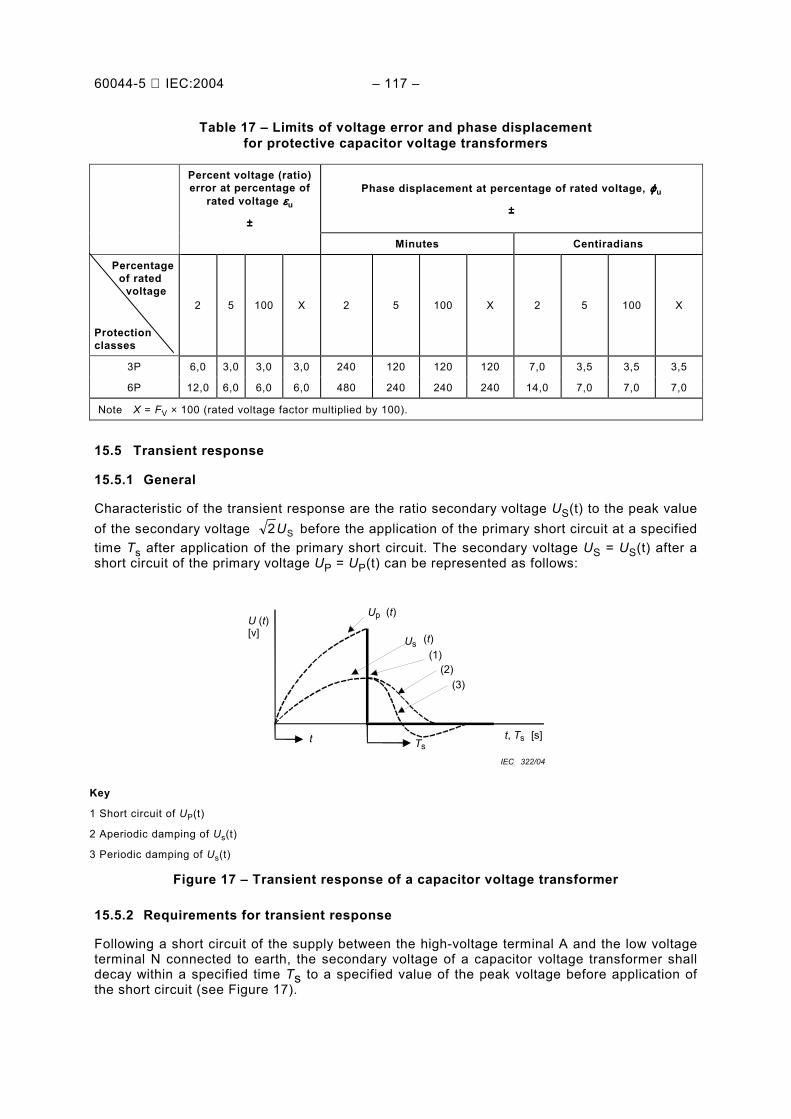
3.1.33 transient response the measured fidelity of the secondary-voltage waveform, compared with the voltage waveform at the high-voltage terminal under transient conditions
3.1.34 mechanical stress the stresses on different parts of the capacitor voltage transformer as a function of four main forces:
− forces on the terminals due to the line connections,
− forces due to the wind on the cross-section of the capacitor voltage transformer with and without line trap mounted on the top of the coupling capacitor,
− seismic forces and
− electrodynamic forces due to short circuit current
3.1.35 voltage-connected CVT CVT which has only one connection to the high voltage line
NOTE Under normal conditions the top connection carries only the current of the capacitor voltage transformer.
3.1.36 current-connected CVT CVT which has two connections to the high voltage line
NOTE The terminals and the top connection are designed to carry the line current under normal conditions.
3.1.37 line trap-connected CVT CVT which supports a line trap on its top
NOTE 1 In this case, the two connections to the line trap carry the HV line current and one connection from the line trap to the CVT carries the CVT current
NOTE 2 The pedestal-mounting line traps in two phases generate additional forces during a short circuit in more than one phase.
3.2 Capacitor voltage divider definitions
3.2.1 capacitor voltage divider a capacitor stack forming an alternating voltage divider
[IEV 436-02-10]
3.2.2 (capacitor) element a device consisting essentially of two electrodes separated by a dielectric
[IEV 436-01-03]
60044-5 IEC:2004 29
3.2.3 (capacitor) unit an assembly of one or more capacitor elements in the same container with terminals brought out
[IEV 436-01-04]
NOTE A common type of unit for coupling capacitors has a cylindrical housing of insulating material and metallic flanges which serve as terminals.
3.2.4 (capacitor) stack an assembly of capacitor units connected in series
[IEV 436-01-05]
NOTE The capacitor units are usually mounted in a vertical array.
3.2.5 capacitor a general term used when it is not necessary to state whether reference is made to a capacitor unit or to a capacitor stack
3.2.6 rated capacitance of a capacitor CR the capacitance value for which the capacitor has been designed
NOTE This definition applies:
• for a capacitor unit, to the capacitance between the terminals of the unit;
• for a capacitor stack, to the capacitance between line and low voltage terminals or between line and earth terminals of the stack;
• for a capacitor divider, to the resultant capacitance: CR =C1C2/(C1 + C2).
3.2.7 coupling capacitor a capacitor used for the transmission of signals in a power system
[IEV 436-02-11]
3.2.8 high voltage capacitor (of a capacitor divider) C1 the capacitor connected between the line terminal and the intermediate voltage terminal of a capacitor divider
[IEV 436-02-12 modified]
3.2.9 intermediate voltage capacitor (of a capacitor divider) C2 the capacitor connected between the intermediate voltage and the low voltage terminals of a capacitor divider
[IEV 436-02-13]
60044-5 IEC:2004 31
3.2.10 intermediate voltage terminal (of a capacitor divider) a terminal intended for connection to an intermediate circuit such as the electromagnetic unit of a capacitor voltage transformer
[IEV 436-03-03]
3.2.11 low voltage terminal of a capacitor divider a terminal (N) intended for connection to earth either directly or via a drain coil of negligible value of impedance, at rated frequency, for power line carrier (PLC) application
[IEV 436-03-04, modified]
3.2.12 capacitance tolerance the permissible difference between the actual capacitance and the rated capacitance under specified conditions
[IEV 436-04-01]
3.2.13 equivalent series resistance of a capacitor virtual resistance which, if connected in series with an ideal capacitor of capacitance value equal to that of the capacitor in question, would have a power loss equal to the active power dissipated in that capacitor under specified operating conditions at a given high frequency
3.2.14 high frequency capacitance (of a capacitor) the effective capacitance at a given frequency resulting from the joint effect of the intrinsic capacitance and the self-inductance of the capacitor
[IEV 436-04-03]
3.2.15 intermediate voltage of a capacitor divider UC the voltage between the intermediate voltage terminal of the capacitor divider and the low voltage terminal, when the primary voltage is applied between the high and low voltage terminals or high voltage terminal and earth terminal
3.2.16 voltage ratio (of a capacitor divider) KCR the ratio of the voltage applied to the capacitor divider to the open-circuit intermediate voltage
[IEV 436-04-05] NOTE 1 This ratio corresponds to the sum of the capacitances of the high voltage and intermediate voltage capacitors divided by the capacitance of the high voltage capacitor: (C1 + C2) / C1 = KCR.
NOTE 2 C1 and C2 include the stray capacitances, which are generally negligible.
3.2.17 capacitor losses the active power dissipated in the capacitor
[IEV 436-04-10]
60044-5 IEC:2004 33
3.2.18 tangent of the loss angle (tanδδδδ) of a capacitor the ratio between the active power Pa and the reactive power Pr: tanδ = Pa/Pr
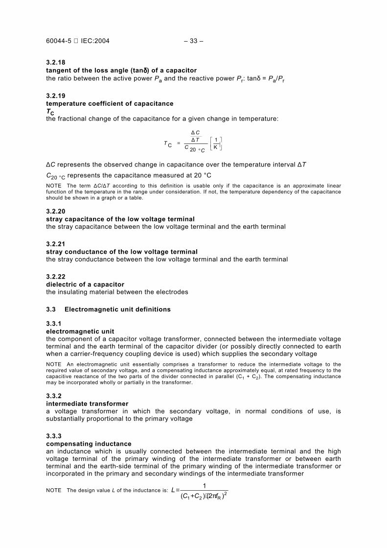
3.2.19 temperature coefficient of capacitance TC the fractional change of the capacitance for a given change in temperature:
°=
K1
20
∆∆
CCC
TC
T
∆C represents the observed change in capacitance over the temperature interval ∆T C20 °C represents the capacitance measured at 20 °C NOTE The term ∆C/∆T according to this definition is usable only if the capacitance is an approximate linear function of the temperature in the range under consideration. If not, the temperature dependency of the capacitance should be shown in a graph or a table.
3.2.20 stray capacitance of the low voltage terminal the stray capacitance between the low voltage terminal and the earth terminal
3.2.21 stray conductance of the low voltage terminal the stray conductance between the low voltage terminal and the earth terminal
3.2.22 dielectric of a capacitor the insulating material between the electrodes
3.3 Electromagnetic unit definitions
3.3.1 electromagnetic unit the component of a capacitor voltage transformer, connected between the intermediate voltage terminal and the earth terminal of the capacitor divider (or possibly directly connected to earth when a carrier-frequency coupling device is used) which supplies the secondary voltage NOTE An electromagnetic unit essentially comprises a transformer to reduce the intermediate voltage to the required value of secondary voltage, and a compensating inductance approximately equal, at rated frequency to the capacitive reactance of the two parts of the divider connected in parallel (C1 + C2). The compensating inductance may be incorporated wholly or partially in the transformer.
3.3.2 intermediate transformer a voltage transformer in which the secondary voltage, in normal conditions of use, is substantially proportional to the primary voltage
3.3.3 compensating inductance an inductance which is usually connected between the intermediate terminal and the high voltage terminal of the primary winding of the intermediate transformer or between earth terminal and the earth-side terminal of the primary winding of the intermediate transformer or incorporated in the primary and secondary windings of the intermediate transformer
NOTE The design value L of the inductance is: 2
R21 )(2)(1
fCCL
π⋅+=
60044-5 IEC:2004 35
3.3.4 damping device devices incorporated in the electromagnetic unit for the purposes of: a) limiting overvoltages which may appear across one or more components; b) and/or to prevent sustained ferro-resonance; c) and/or to achieve a higher performance of the transient response of the capacitor voltage
transformer
3.4 Carrier-frequency accessories definitions
3.4.1 carrier-frequency accessories circuit element intended to permit the injection of carrier frequency signal and which is connected between the low voltage terminal of a capacitor divider unit and earth, having an impedance which is insignificant at power frequency, but appreciable at the carrier frequency. (see Figure A.2)
3.4.2 drain coil an inductance which is connected between the low voltage terminal of a capacitor divider and earth, and whose impedence is insignificant at power frequency, but has a high value at the carrier frequency.
3.4.3 voltage limitation element an element connected across the drain coil or between low voltage terminal of the capacitor voltage divider and earth to limit the overvoltages which appear across the drain coil:
a) at a short circuit between the high-voltage terminal and earth; b) in the case where an impulse voltage is applied between the high voltage terminal and
earth
3.4.4 carrier earthing switch a switch for earthing, when necessary, of the low voltage terminal
4 General requirements
All capacitor voltage transformers shall be suitable for measuring purposes, but, in addition, certain types may be suitable for protection purposes. Capacitor voltage transformers for the dual purpose of measurement and protection shall comply with all clauses of this standard.
5 Service conditions
Detailed information concerning classification of environmental conditions is given in IEC 60721 series.
5.1 Normal service conditions
5.1.1 Ambient air temperature
The capacitor voltage transformers are classified in three categories as given in Table 1.
60044-5 IEC:2004 37
Table 1 Rated ambient temperature categories
Category Minimum temperature °C
Maximum temperature °C
5/40 5 40
25/40 25 40
40/40 40 40
NOTE In the choice of the temperature category, storage and transportation conditions should also be considered.
5.1.2 Altitude
The altitude does not exceed 1 000 m.
5.1.3 Vibrations or earth tremors
Vibrations due to causes external to the capacitor voltage transformer or earth tremors are negligible.
5.1.4 Other service conditions for indoor capacitor voltage transformers
Other considered service conditions are the following:
a) the influence of solar radiation may be neglected; b) the ambient air is not significantly polluted by dust, smoke, corrosive gases, vapours or salt; c) the conditions of humidity are as follows:
1) the average value of the relative humidity, measured during a period of 24 h, does not exceed 95 %;
2) the average value of the water vapour pressure for a period of 24 h, does not exceed 2,2 kPa;
3) the average value of the relative humidity, for a period of one month, does not exceed 90 %;
4) the average value of the water vapour pressure, for a period of one month, does not exceed 1,8 kPa.
For these conditions, condensation may occasionally occur. NOTE 1 Condensation be expected where sudden temperature changes occur in periods of high humidity.
NOTE 2 To withstand the effects of high humidity and condensation, such as breakdown of insulation or corrosion of metallic parts, capacitor voltage transformers designed for such conditions should be used.
NOTE 3 Condensation may be prevented by special design of the housing, by suitable ventilation and heating or by the use of dehumidifying equipment.
5.1.5 Other service conditions for outdoor capacitor voltage transformers
Other considered service conditions are the following:
a) average value of the ambient air temperature, measured over a period of 24 h, does not exceed 35 °C;
b) solar radiation up to a level of 1 000 W/m2 (on a clear day at noon) should be considered;
60044-5 IEC:2004 39
c) the ambient air may be polluted by dust, smoke, corrosive gases, vapours or salt. The pollution does not exceed the pollution levels given in Table 6;
d) the wind pressure does not exceed 700 Pa (corresponding to 34 m/s wind speed); e) account should be taken of the presence of condensation or precipitation.
5.2 Special service conditions
When capacitor voltage transformers may be used under conditions different from the normal service conditions given in 5.1, the users requirements should refer to standardized steps as follows.
5.2.1 Altitude
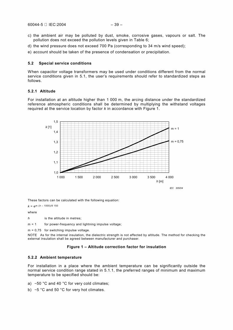
For installation at an altitude higher than 1 000 m, the arcing distance under the standardized reference atmospheric conditions shall be determined by multiplying the withstand voltages required at the service location by factor k in accordance with Figure 1.
1,0
1,1
1,2
1,3
1,4
1,5
1 000 1 500 2 000 2 500 3 000 3 500 4 000 h [m]
m = 1
m = 0,75
k [1]
IEC 305/04
These factors can be calculated with the following equation:
k = em (h 1000)/8 150
where
h is the altitude in metres;
m = 1 for power-frequency and lightning impulse voltage;
m = 0,75 for switching impulse voltage. NOTE As for the internal insulation, the dielectric strength is not affected by altitude. The method for checking the external insulation shall be agreed between manufacturer and purchaser.
Figure 1 Altitude correction factor for insulation
5.2.2 Ambient temperature
For installation in a place where the ambient temperature can be significantly outside the normal service condition range stated in 5.1.1, the preferred ranges of minimum and maximum temperature to be specified should be:
a) −50 °C and 40 °C for very cold climates; b) −5 °C and 50 °C for very hot climates.
60044-5 IEC:2004 41
In certain regions with frequent occurrence of warm humid winds, sudden changes of temperature may occur resulting in condensation even indoors. NOTE Under certain conditions of solar radiation, appropriate measures e.g. roofing, forced ventilation, etc. may be necessary, in order not to exceed the specified temperature rises.
5.2.3 Earthquakes
Requirements and testing are under consideration.
5.3 System earthing
The considered system earthings are:
a) isolated neutral system (see 3.1.18); b) resonant earthed system (see 3.1.21); c) earthed neutral system (see 3.1.23):
1) solidly earthed neutral system (see 3.1.19) 2) impedance earthed (neutral) system (see 3.1.20).
6 Ratings
6.1 Standard values of rated frequency
Standard values are 50 Hz and 60 Hz.
6.2 Standard values of rated voltages
6.2.1 Rated primary voltages UPR
The standard values of rated primary voltage of a capacitor voltage transformer connected between one line of a three-phase system and earth or between a system neutral point and earth shall be 1/ 3 times the values of rated system voltage.
Preferred values are given in IEC 60038.
NOTE The performance of a capacitor voltage transformer as a measuring or protection transformer is based on the rated primary voltage UPR whereas the rated insulation level is based on one of the highest voltages for equipment Um of IEC 60071-1.
6.2.2 Rated secondary voltages
The rated secondary voltage USR shall be chosen according to the practice at the location where the transformer is to be used. The values given below are considered standard values for capacitor voltage transformers connected between one phase and earth in three-phase systems.
1) 1003
V and 1103
V;
2) Based on the current practice in some countries:
a) 1203
V for distribution systems;
60044-5 IEC:2004 43
b) 1153
V for transmission systems.
NOTE 1 The rated secondary voltage for windings intended to produce a residual voltage is given in 15.6.1.
NOTE 2 Whenever possible, the rated transformation ratio should be of a simple value.
6.3 Standard values of rated output
The standard values of rated output at a power factor of 1, expressed in volt-amperes, are: 1,0; 1,5; 2,5; 3,0; 5,0; 7,5 VA (burden range I, in 9.8).
The standard values of rated output at a power factor of 0.8 lagging, expressed in volt-amperes, are: 10; 15; 25; 30; 40; 50; 100 VA (burden range II, in 9.8).
The values underlined are preferred values.
NOTE For a given transformer, provided one of the values of rated output is standard and associated with a standard accuracy class, the declaration of other rated outputs, which may be non-standard values but associated with other standard classes, is not precluded.
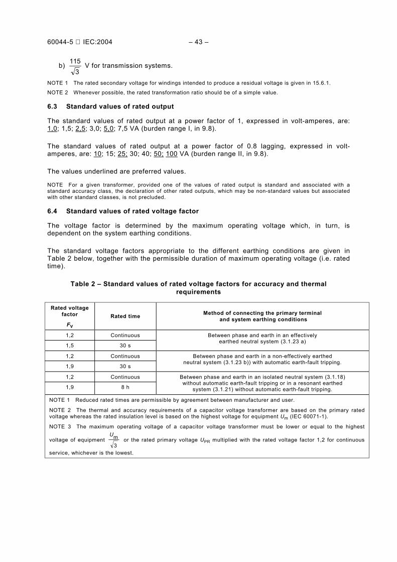
6.4 Standard values of rated voltage factor
The voltage factor is determined by the maximum operating voltage which, in turn, is dependent on the system earthing conditions.
The standard voltage factors appropriate to the different earthing conditions are given in Table 2 below, together with the permissible duration of maximum operating voltage (i.e. rated time).
Table 2 Standard values of rated voltage factors for accuracy and thermal requirements
Rated voltage factor
FV Rated time Method of connecting the primary terminal
and system earthing conditions
1,2
1,5
Continuous
30 s
Between phase and earth in an effectively earthed neutral system (3.1.23 a)
1,2
1,9
Continuous
30 s
Between phase and earth in a non-effectively earthed neutral system (3.1.23 b)) with automatic earth-fault tripping.
1,2
1,9
Continuous
8 h
Between phase and earth in an isolated neutral system (3.1.18) without automatic earth-fault tripping or in a resonant earthed
system (3.1.21) without automatic earth-fault tripping.
NOTE 1 Reduced rated times are permissible by agreement between manufacturer and user.
NOTE 2 The thermal and accuracy requirements of a capacitor voltage transformer are based on the primary rated voltage whereas the rated insulation level is based on the highest voltage for equipment Um (IEC 60071-1).
NOTE 3 The maximum operating voltage of a capacitor voltage transformer must be lower or equal to the highest
voltage of equipment 3mU
or the rated primary voltage UPR multiplied with the rated voltage factor 1,2 for continuous
service, whichever is the lowest.
60044-5 IEC:2004 45
6.5 Limits of temperature rise
Unless otherwise specified, the temperature rise ∆T of a capacitor voltage transformer at the specified voltage, at rated frequency and at rated burden or at the highest rated burden if there are several rated burdens, at any power factor between 0,8 lagging and unity, shall not exceed the appropriate value given in Table 3.
If ambient temperatures in excess of the values given in 5.1 are specified, the permissible temperature rise ∆T in Table 3 shall be reduced by an amount equal to the excess ambient temperature.
If a capacitor voltage transformer is specified for service at an altitude in excess of 1 000 m and tested at an altitude below 1 000 m, the limits of temperature rise ∆T given in Table 3 shall be reduced by the following amounts for each 100 m that the altitude at the operating site exceeds 1 000 m:
a) oil-immersed magnetic units: 0,4 %; b) dry-type magnetic units: 0,5 % (see Figure 2).
0,8
0,85
0,9
0,95
1,0
0 1 000 2 000 3 000 4 000 5 000
h [m]
K0 [1]
a) oil
b) dry
IEC 306/04
The altitude correction factor for the temperature rise ho
ho T∆
∆=
TK with
hT∆ temperature rise at altitude h > 1 000 m and
hoT∆ limits of temperature rise T∆ specified in Table 3 at altitudes ho ≤1 000 m.
Figure 2 Altitude correction factor for the temperature rise
The temperature rise ∆T of the windings is referred to the lowest class of insulation either of the winding itself or of the surrounding medium in which it is embedded. The maximum temperature rises of the insulation classes are as given in Table 3.
60044-5 IEC:2004 47
Table 3 Limits of temperature rise of windings
Class of insulation (in accordance with IEC 60085) Maximum temperature rise
∆∆∆∆T
K
All classes, immersed in oil
When the magnetic unit is not so fitted or arranged, the temperature rise ∆T of the oil at the top of the housing shall not exceed 50 K.
60
All classes, immersed in oil and hermetically sealed
When the magnetic unit has an inert gas above the oil, or is hermetically sealed, the temperature rise ∆T of the oil at the top of the housing shall not exceed 55 K.
65
All classes, immersed in bituminous compound 50
Classes not immersed in oil or bituminous compound:
Y
A
E
B
F
H
The temperature rise ∆T measured on the external surface of the core and other metallic parts which are in contact with, or adjacent to, insulation shall not exceed the appropriate values.
45
60
75
85
110
135
NOTE For some materials (e.g. resin) the manufacturer should specify the relevant insulation class.
7 Design requirements
7.1 Insulation requirements
The choice of the insulation level for capacitor voltage transformer shall be made in accordance with the standard insulation levels in Table 4. The rated insulation levels shall be based on its highest voltage for equipment Um.
Applied general rules:
− The rated positive wet switching impulse withstand voltage is the base for the determination of the minimum arcing distance (external insulation) of the capacitor voltage transformer.
− The strength of the external insulation is usually tested wet with the rated short duration power frequency withstand voltage (range I) or with the positive wet switching impulse withstand voltage (range II) (see 9.5).
− The value of the rated lightning impulse withstand voltage is one factor with which to determine the strength of the dielectric of the capacitors and the strength of the insulation of the electromagnetic unit.
− In IEC 60071-1, for each Um only two standard withstand voltages are sufficient to define the standard insulation level for the equipment:
• range I: 72,5 kV ≤ Um ≤ 300 kV: rated lightning impulse withstand voltage and rated short-duration power-frequency withstand voltage;
• range II: 300 kV ≤ Um ≤ 765 kV: rated switching and rated lightning impulse withstand voltages.
60044-5 IEC:2004 49
− Due to the non-self-restoring internal insulation of capacitor voltage transformers, for range II three standard withstand voltages are specified in Table 4. The short duration power frequency withstand voltage test has been specified for range II as a routine test with partial discharge measurement. The stress with a.c. voltage determines the long term behaviour of the non-self-restoring internal insulation of the capacitor voltage transformer.
− The rated short-duration power frequency withstand voltage test (Table 4, column 4), with partial discharge (PD) measurement in range II is an indication for the stress on the insulation of the capacitor voltage transformer.
− The rated insulation level is based on the highest voltage for equipment Um, whereas the thermal and accuracy requirements of a voltage transformer are based on the primary rated voltage UPR.
− The choice of the insulation level shall be made in accordance with 6.2.1 and IEC 60071-1.
Table 4 Standard insulation levels
1 2 3 4
Highest voltage for equipment Um
(r.m.s.)
Rated switching impulse withstand
voltage
(peak)
Rated lightning impulse withstand
voltage
(peak)
Rated short-duration power-frequency withstand voltage
(routine test)
(r.m.s.)
Range
kV kV kV kV
I
72,5 100 123
145
170
245
325 450 450 550
550 650
650 750
950
1 050
140 185 185 230
230 275
275 325
395 460
II
300
362
420
525
765
750 850
850 950
950
1 050
1 050 1 175
1 425 1 550
950
1 050
1 050 1 175
1 300 1 425
1 425 1 550
1 950 2 100
395 460
460 510
570 630
630 680
880 975
NOTE 1 For exposed installations it is recommended to choose the highest insulation level.
NOTE 2 As the test voltage levels for Um = 765 kV have not as yet been finally settled, some interchange between switching and lightning impulse test levels may become necessary.
60044-5 IEC:2004 51
7.2 Other insulation requirements
7.2.1 Low voltage terminal of the capacitor voltage divider
Capacitor voltage dividers with a low-voltage terminal shall be subjected for 1 min to a test voltage between the low-voltage and earth terminals. The test voltage shall be an a.c. voltage of 4 kV (r.m.s. value).
7.2.2 Low voltage terminal exposed to weather
If the low voltage terminal is exposed to the weather, it shall be subjected for 1 min to an a.c. voltage of 10 kV (r.m.s. value) between the low-voltage and earth terminals.
− During this test the magnetic unit is not disconnected. NOTE The test voltages are applicable to capacitor voltage transformers with and without carrier-frequency accessories with overvoltage protection.
− If a protection gap between the low voltage terminal and earth is incorporated, it should be prevented from functioning during the tests. The carrier frequency accessories should be disconnected during the tests.
− If the test voltage is too low for the insulation co-ordination of the carrier-frequency accessories with the low voltage terminal, a higher value may be agreed upon the request of the purchaser.
7.2.3 Partial discharges
The partial discharge level shall not exceed the limits specified in Table 5 at the partial discharge test voltage specified in the same table, after a pre-stressing performed according to the procedures of 10.2.3.2.
Partial discharge requirements are applicable to the complete capacitor voltage divider, or to a capacitor unit which is a part of a stack or to a capacitor stack which is a part of the capacitor voltage divider.
The partial discharge measurement is performed with the electromagnetic unit disconnected. The low electrical stress of the insulation in the electromagnetic unit doesnt require a partial discharge measurement.
60044-5 IEC:2004 53
Table 5 Partial discharge test voltages and permissible levels
Type of earthing of the system PD test voltage (r.m.s.) Permissible PD level (pC)
Insulation immersed in liquid
Earthed neutral system
Um
3
m 1,2U
10
5
Insulated or non-effectively earthed neutral system
1,2 Um
3
m 1,2U
10
5
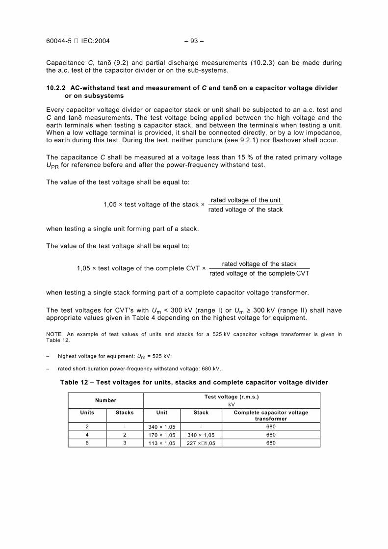
NOTE 1 If the neutral system is not defined, the values given for isolated or non-effectively earthed systems are valid. NOTE 2 The permissible PD level is also valid for frequencies different from the system frequency. NOTE 3 If only parts of the capacitor voltage divider are tested, the value of the test voltage will be equal to :
1,05 × test voltage of the CVT × CVTtheofvoltagerated
unittheofvoltagerated
or
1,05 × test voltage of the CVT × CVTtheofvoltagerated
stacktheofvoltagerated
7.2.4 Chopped lightning impulse test
The test is intended to check the internal connections of the capacitor.
If additionally specified, the complete capacitor voltage transformer shall also be capable of withstanding a chopped lightning impulse voltage having a peak value of 115 % of the rated lightning impulse voltage.
7.2.5 Capacitance at power frequency
The capacitance C of a unit, a stack and a capacitor voltage divider shall not differ from the rated capacitance by more than −5 % to +10 %. The ratio of the capacitances of any two units forming part of a capacitor stack shall not differ by more than 5 % from the reciprocal ratio of the rated voltages of the units.
NOTE 1 n
CC
o=
where
n is the number of elements in series;
Co is the capacitance of one element.
NOTE 2 The actual capacitance should be measured, or referred to, at the temperature at which the rated capacitance is defined.
7.2.6 Losses of the capacitor at power frequency
The requirements relating to capacitor losses, expressed as tanδ measured at 10 kV and 0,9 to 1,1 times the UPR may be agreed upon between manufacturer and purchaser.
NOTE 1 The purpose is to check the uniformity of the production. Limits for the permissible variations may be the subject of an agreement between manufacturer and purchaser.
60044-5 IEC:2004 55
NOTE 2 The tanδ value is dependent on the insulation design and the voltage, the temperature and the measuring frequency.
NOTE 3 The tanδ value of certain types of dielectrics is a function of the energization time before the measurement.
NOTE 4 The losses of the capacitor are an indication of the drying and impregnation process.
NOTE 5 For information, typical tanδ values for dielectrics which are impregnated with mineral oil or synthetic oil are at 20 °C (293 K):
a) Paper: ≤ 5 × 10⁻³
b) Mixed: film-paper-film and paper-film-paper ≤ 2 × 10⁻³
c) Film: ≤ 1 × 10⁻³
7.2.7 Electromagnetic unit
7.2.7.1 Insulation level
a) The rated lightning impulse withstand voltage of the electromagnetic unit shall be equal to the:
test impulse voltage of the CVT × 21
1CC +
C (peak)
b) The rated short-duration power-frequency withstand voltage of the electromagnetic unit shall be equal to:
UPR × 3,3 × 21
1CC +
C (r.m.s.)
NOTE 1 The tests a) can be performed on a complete capacitor voltage transformer.
NOTE 2 For the test b) the electromagnetic unit may be disconnected from the capacitor divider.
NOTE 3 The factor 3,3 is fixed for all Um values and covers the worst case. (The factor
kV145
kV2753
kV72,5
kV14033,3
×≈×= is the correlation factor between a.c. test voltage and Um.)
7.2.7.2 Between-section insulation requirements
For windings divided into two or more sections, the between-section insulation shall be capable of withstanding a rated power-frequency short-duration withstand voltage of 3 kV r.m.s. for 1 min.
The winding insulation shall be capable of withstanding a rated power-frequency short-duration withstand voltage of 3 kV r.m.s. for 1 min.
7.2.8 External insulation requirements
For outdoor insulation susceptible to contamination, the minimum rated specific creepage distance measured on the insulation surface in millimetres is given in Table 6.
60044-5 IEC:2004 57
Table 6 Creepage distance
Pollution level Minimum rated specific creepage distancea mm/kV b
Creepage distance
Arcing distance
I Light 16 ≤ 3,5
II Medium 20 ≤ 3,5
III Heavy 25 ≤ 4,0
IV Very heavy 31 ≤ 4,0
a For the actual creepage distance, the specified manufacturing tolerances are applicable (see IEC 62155). b Ratio of the creepage distance measured in millimetres between phase and earth over the r.m.s. phase to phase
value of the highest voltage in kV for the equipment Um (see IEC 60071-1). For other information and manufacturing tolerances on the creepage distance see IEC 60815.
NOTE 1 It is recognized that the performance of surface insulation is greatly affected by insulator shape.
NOTE 2 In very lightly polluted areas, specific rated creepage distances lower than 16 mm/kV can be used depending on service experience. 12 mm/kV seems to be a lower limit.
NOTE 3 In the case of exceptional pollution severity, a specific rated creepage distance of 31 mm/kV may not be adequate. Depending on service experience and/or on laboratory test results, a higher value of specific creepage distance can be used, but in some instances the practicability of washing may have to be considered.
NOTE 4 The values are for procelain insulators. Composite insulators exist which have better performance against pollution, according to IEC 61462.
7.3 Short-circuit withstand capability
The capacitor voltage transformer shall be designed and constructed to withstand without damage, when energized at rated voltage, the mechanical, electrical and thermal effects of an external short-circuit at the secondary winding(s) for the duration of 1 s.
7.4 Ferro-resonance
7.4.1 General
At any voltage below FV × UPR and at any burden between 0 and rated burden, the ferro-resonance of the CVT incepted by switching operations or transients on the primary or secondary terminals shall not be sustained.
7.4.2 Transients of ferro-resonance oscillations
$ε F : Maximum instantaneous error
ÛS : Secondary voltage (peak)
UP : Primary voltage (r.m.s.)
UPR : Rated primary voltage (r.m.s.)
KR : Transformation ratio
TF : Duration of ferro-resonance
P
PFSR
R
P
R
PFS
F2
2
2
2
UU)(TUK
KU
KU
)(TUε
⋅
⋅−⋅=
⋅
⋅−
=
60044-5 IEC:2004 59
Maximum instantaneous error εF after duration TF :
a) Effectively earthed neutral system (see Table 7a)
Table 7a Ferro-resonance requirements
Primary voltage Up
(r.m.s.)
Ferro-resonance oscillation duration TF
s
Error $ε F
after duration TF %
0,8 ⋅ UPR ≤ 0,5 ≤ 10
1,0 ⋅ UPR ≤ 0,5 ≤ 10
1,2 ⋅ UPR ≤ 0,5 ≤ 10
1,5 ⋅ UPR ≤ 2 ≤ 10
b) Non-effectively earthed neutral system or isolated neutral system (see Table 7b)
Table 7b Ferro-resonance requirements
Primary voltage Up
(r.m.s.)
Ferro-resonance oscillation duration TF
s
Error $ε F
after duration TF %
0,8 ⋅ UPR ≤ 0,5 ≤ 10
1,0 ⋅ UPR ≤ 0,5 ≤ 10
1,2 ⋅ UPR ≤ 0,5 ≤ 10
1,9 ⋅ UPR ≤ 2 ≤ 10
7.5 Electromagnetic emission requirements
7.5.1 Radio interference voltage (RIV)
This requirement applies to capacitor voltage transformers having Um ≥ 123 kV to be installed in air-insulated substation. The radio interference voltage shall not exceed 2 500 µV at 1,1 Um/ 3 .
NOTE This requirement is included to meet some electromagnetic compatibility regulations.
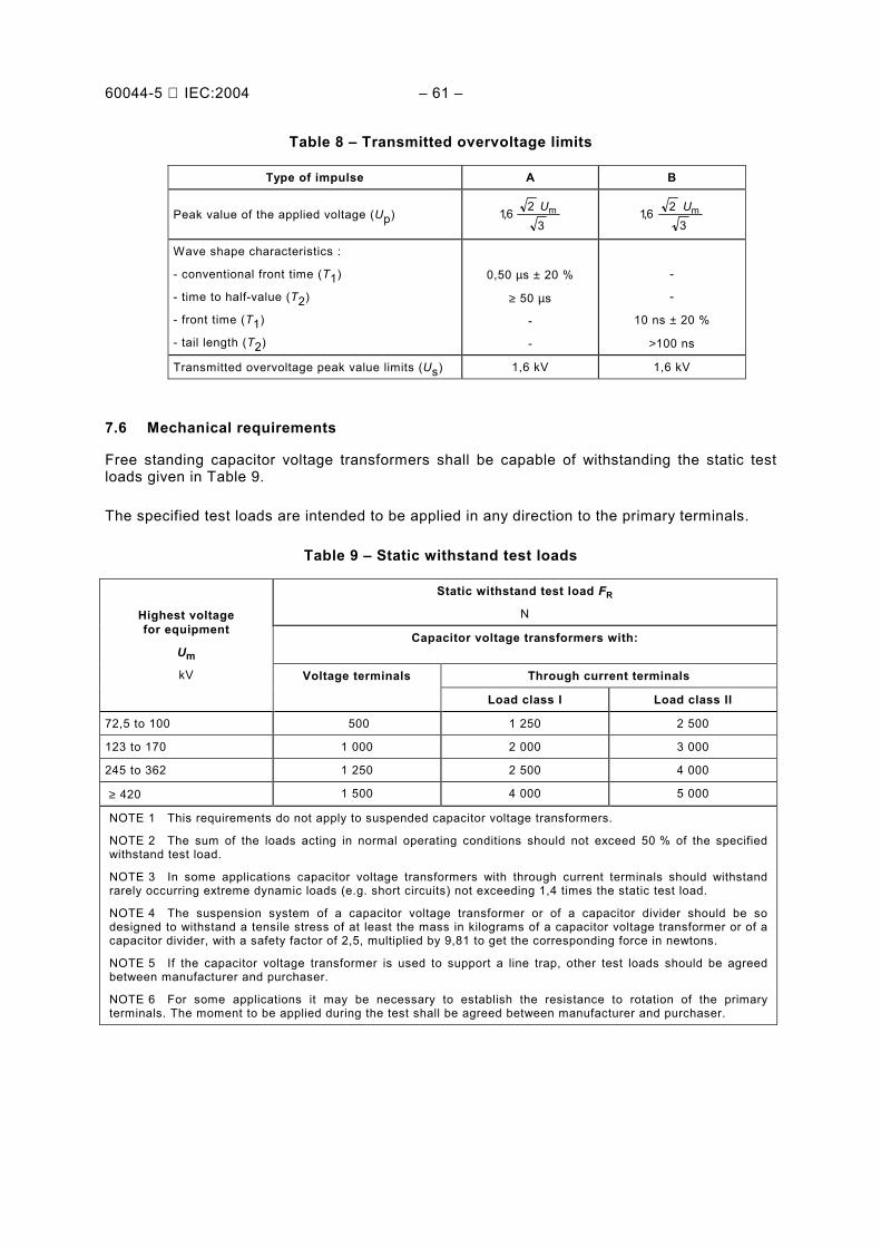
7.5.2 Transmitted overvoltage (TO)
The overvoltages transmitted from the primary to the secondary terminals shall not exceed the values given in Table 8 under test and measuring conditions described in IEC 60044-2.
Type A impulse requirement applies to capacitor voltage transformers for air-insulated substations, while impulse B requirement applies to capacitor voltage transformers installed in gas insulated metal-enclosed substations (GIS).
NOTE 1 This requirement is included to meet some electromagnetic compatibility regulations.
NOTE 2 Type A impulse is representative of voltage oscillations due to spark-gap flashover and switchgear operation. Type B is representative of the steep front impulses produced during switchgear operations.
60044-5 IEC:2004 61
Table 8 Transmitted overvoltage limits
Type of impulse A B
Peak value of the applied voltage (Up) 3
26,1 mU 3
26,1 mU
Wave shape characteristics :
- conventional front time (T1)
- time to half-value (T2)
- front time (T1)
- tail length (T2)
0,50 µs ± 20 %
≥ 50 µs
-
-
-
-
10 ns ± 20 %
>100 ns
Transmitted overvoltage peak value limits (Us) 1,6 kV 1,6 kV
7.6 Mechanical requirements
Free standing capacitor voltage transformers shall be capable of withstanding the static test loads given in Table 9.
The specified test loads are intended to be applied in any direction to the primary terminals.
Table 9 Static withstand test loads
Static withstand test load FR
N
Capacitor voltage transformers with:
Through current terminals
Highest voltage for equipment
Um
kV Voltage terminals
Load class I Load class II
72,5 to 100 500 1 250 2 500
123 to 170 1 000 2 000 3 000
245 to 362 1 250 2 500 4 000
≥ 420 1 500 4 000 5 000
NOTE 1 This requirements do not apply to suspended capacitor voltage transformers.
NOTE 2 The sum of the loads acting in normal operating conditions should not exceed 50 % of the specified withstand test load.
NOTE 3 In some applications capacitor voltage transformers with through current terminals should withstand rarely occurring extreme dynamic loads (e.g. short circuits) not exceeding 1,4 times the static test load.
NOTE 4 The suspension system of a capacitor voltage transformer or of a capacitor divider should be so designed to withstand a tensile stress of at least the mass in kilograms of a capacitor voltage transformer or of a capacitor divider, with a safety factor of 2,5, multiplied by 9,81 to get the corresponding force in newtons.
NOTE 5 If the capacitor voltage transformer is used to support a line trap, other test loads should be agreed between manufacturer and purchaser.
NOTE 6 For some applications it may be necessary to establish the resistance to rotation of the primary terminals. The moment to be applied during the test shall be agreed between manufacturer and purchaser.
60044-5 IEC:2004 63
7.7 Tightness of capacitor voltage divider and electromagnetic unit
7.7.1 Capacitor voltage divider
A capacitor unit or the complete assembled capacitor voltage divider shall be tight in the full temperature range specified for the applicable temperature category.
7.7.2 Electromagnetic unit
The electromagnetic unit shall be tight in the full temperature range specified for the applicable temperature category.
8 Classification of tests
The tests specified in this standard are classified as type tests, routine tests and special tests. The type and routine tests shall be carried out in the same sequency as outlined in the flow chart (see Figure 3). At the beginning and at the end of the test sequence, capacitance C, tanδ and accuracy shall be measured.
The classification is as follows:
• Type test A test made on one transformer or two transformers of each type to demonstrate that all
transformers made according to the same specification comply with the requirements not covered by routine tests. NOTE 1 A type test may also be considered valid if it is made on a transformer which has minor deviations. Such deviations should be subject to agreement between manufacturer and purchaser.
NOTE 2 The type test must follow the procedure as specified in the flow chart of Figure 3.
• Routine test A test to which each individual transformer is subjected.
• Special test A test other than a type test or a routine test, that shall be performed upon agreement
between manufacturer and purchaser.
8.1 Type tests
The following tests are type tests. For details, reference should be made to the relevant subclauses:
a) accuracy check (10.6); b) temperature rise test (9.1);
c) capacitance and tanδ measurement at power-frequency (9.2); d) chopped impulse test (9.4.3); e) EMC radio interference voltage (RIV) tests, if applicable (9.10); f) short circuit withstand capability test (9.3); g) lightning impulse test (9.4.2);
h) switching impulse test under wet conditions for the voltage range ≥ 300 kV (9.5.2); i) wet test for outdoor type transformers with AC voltage for the voltage range Um< 300 kV
(9.5.1); j) transient response test (9.9) (valid only for protection capacitor voltage transformers);
60044-5 IEC:2004 65
k) ferro-resonance test (9.6); l) tightness of electromagnetic unit (9.7); m) accuracy tests (9.8).
After the capacitor voltage transformers have been subjected to the dielectric type tests of 8.1, they shall be subjected to all routine tests of 8.2.
Repeated power frequency tests shall be performed at 80 % of the specified test voltage. The type tests can be carried out on one or two capacitor voltage transformers according to the sequence of the flow chart given in Figure 3.
The capacitance C of a unit or a stack or a capacitor voltage divider shall not change by more
than on
1∆CC
CC =≤ during any test procedures (7.2.5).
The choice of one or two transformers is left to the manufacturer.
The type test report shall include the results of the routine tests.
NOTE 1 ∆C is the measured change of the capacitance C.
NOTE 2 By an agreement between the manufacturer and the purchaser the order of the test sequence (Figure 3) can be modified.
60044-5 IEC:2004 67
End of theroutine tests
(h) W et switchingimpulse test
Two CVT units First CVT unit
One CVT unit Two CVT unitsSecond CVT unit
(a) Accuracy check
(c) C + tan δ test (c) C + tan δ
(e) EMC RIV test if applicable
(d) Chopped impulse test
(b) Temp . - rise test
(j) Transient response testif applicable
(k) Ferro - resonance test
(f) Short circuit test
(e) Tightness of e.m.u. test
(m) Accuracy tests
End of the type test
End of the type test
g) Lightning impulse test
(i) AC test wet
Range I < 300 kV
Range II> 300 kV
Routine test
(b) C + tan δ test
(e) Verification of terminal markings
(f) AC - test o n the electromagnetic unit
(g) AC - test of low voltage terminal
(h) AC - test of secondary windings
(i) Ferro - resonance check
(j) Accuracy check
(c) AC test (c) AC test
(a) Tightness of capacitor s voltage divider
(b) C + tan δ test
80 % prest . voltage(d) PD test
( c ) AC + (d) PD test
Method A Method B
Type test
Type test
Figure 3a Type test
Figure 3b Routine test
IEC 307/04
IEC 308/04
Figure 3 Flow charts test sequence to be applied when performing the type test (Figure 3a) and routine test (Figure 3b)
60044-5 IEC:2004 69
8.2 Routine tests
The following tests are routine tests. For details, reference should be made to the relevant sub-clauses:
a) tightness of capacitor voltage divider (10.1);
b) capacitance and tanδ measurement at power-frequency (9.2); c) power-frequency withstand test (10.2); d) measurement of partial discharges (10.2.3); e) verification of terminal markings (10.3); f) power-frequency withstand tests on the electromagnetic unit (10.4); g) power-frequency withstand test on low voltage terminal (10.2.4); h) power-frequency withstand tests on secondary windings (10.4.2); i) ferro-resonance check (10.5); j) accuracy check (determination of errors) (10.6).
Apart from the fact that determination of errors j) shall be performed after the tests of items b), c), d), e), f), g) and h), the order or possible combination of the other tests is not standardized.
Repeated power-frequency tests shall be performed at 80 % of the specified test voltage.
Non repeated power-frequency tests shall be performed at 100 % of the specified test voltage.
8.3 Special tests
The following tests are special tests. For details, reference should be made to the relevant sub-clause:
a) measurement of the transmission factor of high frequency overvoltages (11.1); b) mechanical strength test (11.2); c) determination of the temperature coefficient (11.3); d) tightness design test of capacitor units (11.4).
8.4 Test sequence for one or two units
Flow chart test sequence shall be considered mandatory (see Figure 3).
NOTE Small modification of the test sequence may be agreed between manufacturer and purchaser.
9 Type test
9.1 Temperature-rise test
The test shall be made to prove compliance with 6.5.
The test can be performed on the complete capacitor voltage transformer or on the electro-magnetic unit alone. When performed on the complete capacitor voltage transformer, the primary voltage UP shall be adjusted in accordance with Table 10.
60044-5 IEC:2004 71
When performed on the electromagnetic unit the intermediate transformer shall be adjusted in such a way to have a secondary voltage US in accordance with Table 10.
The temperature-rise test shall be performed with the rated burden or with the highest rated burden, if there are several rated burdens (6.5). The temperature shall be recorded.
When there is more than one secondary winding, the test shall be made with the appropriate rated burden connected to each secondary winding simultaneously, unless otherwise agreed between manufacturer and purchaser.
The residual voltage winding shall be loaded in accordance with 15.6.5.1.
The test site ambient temperature shall be between 10 °C and 30 °C.
The capacitor voltage transformers or the electromagnetic unit alone, irrespective of voltage factor and time rating, shall be tested at 1,2 times the rated primary voltage. The secondary side shall be at the corresponding value. The test shall be continued until the temperature (of the electromagnetic unit) has reached a steady state.
The electromagnetic unit can be considered to be in steady state conditions when the rate of temperature rise does not exceed 1 K per hour. The temperature rise of the windings shall be determined by the resistance variation method.
The temperature rise of parts other than windings may be measured by thermometers or thermocouples.
The ambient temperature can be measured by thermometers or thermocouples immersed in temperature insulation material, so that the system has a thermal time constant of the same order of the electromagnetic unit alone.
60044-5 IEC:2004 73
Table 10 Test voltage for temperature rise test
Burden Rated burden Thermal limiting output a
Voltage factor & fault
duration time
FV = 1.2
continuous
FV = 1.5 or 1.9
30 s
FV = 1.9
8 h
-
-
Configuration of test
Electro-magnetic
unit
Complete capacitor voltage
transformer
Electro-magnetic
unit
Complete capacitor voltage
transformer
Electro-magnetic
unit
Complete capacitor voltage
transformer
Electro-magnetic
unit
Complete capacitor voltage
transformer
Test voltage till temperature rise is below 1 K/h.
R
PRS
1,2KUU =
UP = 1,2 UPR
R
PRS
1,2KUU =
UP = 1,2 UPR
R
PRS
1,2KUU =
UP = 1,2 UPR CR
PRC K
UU =
UP = UPR
Test voltage for fault duration time
R
PRVS
. K
UFU = PRVP UFU ⋅=
R
PRS
. ,91KUU =
UP = 1,9 UPR
a Additional test if a thermal limiting output is specified
9.2 Capacitance and tanδδδδ measurement at power-frequency
9.2.1 Capacitance measurement
The test may be carried out on the capacitor voltage divider, or on a capacitor stack or on separate units. During this test the electromagnetic unit shall be disconnected.
The capacitance shall be measured using a method that excludes errors due to harmonics and to accessories in the measuring circuit. The uncertainty of the measuring method shall be indicated in the test report.
The final capacitance measurement shall be carried out at UPR ± 10 % after the dielectric type and/or routine tests. The measurement shall be carried out at rated frequency or by agreement between 0,8 and 1,2 times of rated frequency.
In order to reveal any change in capacitance due to the puncture of one or more elements, a preliminary capacitance measurement shall be made before the dielectric type and/or routine tests, at a sufficiently low voltage (less than 15 % of rated voltage) to ensure that no puncture of an element will occur.
NOTE 1 When there is an intermediate voltage terminal which is still accessible when the capacitor voltage transformer is completely assembled the following should be measured:
a) the capacitance between line and low voltage terminal or line and earth terminal,
b) the capacitance between the intermediate and low voltage terminals or intermediate and earth terminal.
NOTE 2 If the dielectric system of the capacitor is such that the measured capacitance varies with the voltage, it is more meaningful to repeat the capacitance measurement after the voltage test at the same voltage as that previously used and then at the measuring voltage which shall be not less than the rated voltage.
60044-5 IEC:2004 75
NOTE 3 If the number of elements in series in the tested unit is large, it may be difficult to ascertain whether no puncture has occurred because of the following uncertainties:
− reproducibility of the measurement;
− capacitance change caused by the mechanical forces on the elements during the dielectric tests;
− capacitance change caused by temperature difference of the capacitor before and after the tests.
In this case, it should be proved by the manufacturer, for example by comparing the capacitance variations of capacitors of the same type and/or by calculation of the capacitance change caused by the temperature increase during the test, that no puncture had occurred. To reduce the measurement uncertainty it may be convenient to carry out these measurements on each unit.
9.2.2 Tan δδδδ measurement
The capacitor losses (tan δ) shall be measured at UPR ± 10 % together with the capacitance measurements, using a method that excludes errors due to harmonics and to accessories in the measuring circuit. The accuracy of the measuring method shall be given. The measure-ment shall be carried out at the rated frequency or by agreement at between 0,8 and 1,2 times rated frequency.
9.3 Short-circuit withstand capability test
This test shall be made to prove compliance with 7.3. For this test, the transformer shall be initially at a temperature between 10 °C and 30 °C. The capacitor voltage transformer shall be energized between high voltage terminal and earth and the short-circuit applied between the secondary terminals. One short-circuit shall be applied for the duration of 1 s. The current shall be measured and recorded.
NOTE This requirement applies also to the cases in which fuses are an integral part of the transformer.
During the short-circuit, the r.m.s. value of the applied voltage at the transformer terminals shall be not less than the rated primary voltage UPR between phase and earth.
In the case of transformers provided with more than one secondary winding, or section, or with tappings, the test connection shall be agreed between manufacturer and purchaser.
The capacitor voltage transformer shall be deemed to have passed this test if, after cooling to ambient temperature, it satisfies the following requirements:
a) it is not visibly damaged; b) its errors do not differ from those recorded before the tests by more than half the limits of
error in its accuracy class and there is no significant change in the value of the capacitance; c) it withstands the dielectric test specified in Clause 10; d) on examination, the insulation next to the surface of both primary and secondary windings of
the electromagnetic unit does not show significant deterioration (e.g. carbonization). The examination indicated in d) is not required if the current density in the winding does not exceed 160 A/mm2 where the winding is of copper of conductivity not less than 97 % of the value given in IEC 60028. The current density is to be based on the measured symmetrical r.m.s. short-circuit current in the secondary winding. NOTE For the examination of the variation of the capacitance, see Notes 1, 2 and 3 of 9.2.1.
60044-5 IEC:2004 77
9.4 Impulse tests
9.4.1 General
Impulse tests shall be performed on a complete capacitor voltage transformer in accordance with IEC 60060-1.
The test voltage shall be applied between high voltage terminal and earth. The earth terminal of the primary winding of the intermediate transformer, the low voltage terminal of the capacitor voltage divider, one of the terminals of each secondary winding and the frame shall be earthed during the test.
The impulse test generally consists of voltage application at reference and rated voltage levels. The reference impulse voltage shall be between 50 % and 75 % of the rated impulse withstand voltage.
The peak value and the wave-shape of the impulse voltage shall be recorded.
Evidence of insulation failure due to the test may be given by variation in the wave-shape at both reference and rated withstand voltage. For the failure detection the record of earth current (s) or of voltages appearing across the secondary winding (s), shall be taken in addition to the voltage record.
NOTE 1 A failure of the capacitor voltage transformer will be detected during the final routine test.
NOTE 2 The earth connections may be made through suitable current recording devices.
NOTE 3 For this test, overvoltage limitation elements shall be disconnected.
9.4.2 Lightning-impulse test
The waveform of the applied impulses shall be in accordance with IEC 60060-1, but the front time may be increased to a maximum of 8 µs, owing to the limitations of the testing equipment.
The test voltage shall have the appropriate value given in Table 4 depending on the highest voltage for equipment and the specified insulation level.
a) Range I: Um < 300 kV
The test shall be performed with both positive and negative polarities. Fifteen consecutive impulses of each polarity, not corrected for atmospheric conditions, shall be applied.
The capacitor voltage transformer passes the test if for each polarity:
− no disruptive discharge occurs in the non-self-restoring internal insulation,
− no flashovers occur along the non-self-restoring external surface insulation,
− no more than two flashovers occur across the self-restoring external insulation,
− no other evidence of insulation failure is detected (e.g., variations in the waveshape of the recorded quantities for the same voltage level. Overvoltage limitation elements may have different influence on the waveshape at different voltage levels).
NOTE The application of 15 positive and 15 negative impulses is specified for testing the internal and external insulation. If other tests are agreed between manufacturer and purchaser to check the external insulation (see 9.5.1), the number of lightning impulses may be reduced to three of each polarity, not corrected for atmospheric conditions.
60044-5 IEC:2004 79
b) Range II: Um ≥ 300 kV
The test shall be performed with both positive and negative polarities. Three consecutive impulses of each polarity, not corrected for atmospheric conditions, shall be applied.
The capacitor voltage transformer passes the test if:
− no disruptive discharge and no external breakdown occurs,
− no other evidence of insulation failure is detected (e.g., variations in the waveshape of the recorded quantities, taking into account the remarks for range I ),
9.4.3 Chopped impulse test
The test shall be carried out on a complete capacitor voltage transformer with negative polarity only and combined with the negative polarity lightning impulse test in the manner described below.
The voltage shall be a standard lightning impulse as defined in IEC 60060-1, chopped after the crest value has been reached between 2 µs and 8 µs. The chopping circuit shall be so arranged that the amount of overswing of opposite polarity of the recorded impulse shall be limited to 30 % of the peak value. The lightning impulse shall be chopped with a suitable gap.
The test voltage of the full impulses shall have the appropriate value, given in Table 4 depending on the highest voltage for the equipment and the specified insulation level. The chopped impulse test voltage shall have this value multiplied by 1,15.
The sequence of impulse applications shall be as follows:
a) for capacitor voltage transformers rated for Um < 300 kV
− one full impulse;
− two chopped impulses;
− fourteen full impulses;
b) for capacitor voltage transformers rated for Um ≥ 300 kV
− one full impulse;
− two chopped impulses;
− two full impulses.
Differences in waveshape of full wave applications before and after the chopped impulses are an indication of an internal fault. Flashovers during chopped impulses across self-restoring external insulation shall be disregarded in the evaluation of the behaviour of the insulation.
NOTE The chopped impulse test replaces the discharge test in IEC 60358.
9.5 Wet test for outdoor capacitor voltage transformer
The wetting procedure shall be in accordance with IEC 60060-1.
9.5.1 Capacitor voltage transformer having Um < 300 kV (range I)
The test shall be performed on a complete capacitor voltage transformer with rated short duration power frequency withstand voltage of the appropriate value given in Table 4 depend-ing on the highest voltage for equipment applying corrections for atmospheric conditions.
60044-5 IEC:2004 81
During the wet a.c. test the damping and protective devices shall be disconnected. If the intermediate connection between the electromagnetic unit and the capacitor divider is an inside type, the electromagnetic unit can be disconnected. If the intermediate connection between the electromagnetic unit and the capacitor divider is an outside type, the electromagnetic unit can be disconnected but then it shall be wet tested separately with the a.c. voltage and duration as specified in 10.4.1.
9.5.2 Capacitor voltage transformer having Um ≥≥≥≥ 300 kV (range II)
The test shall be performed on a complete capacitor voltage transformer in accordance with 9.4.1 only with positive switching impulse voltage of the appropriate value given in Table 4, depending on the highest voltage for the equipment and the rated insulation level.
Fifteen consecutive impulses, corrected for atmospheric conditions, shall be applied. Outdoor type transformers shall be subjected to the wet test. Dry test is not required.
The capacitor voltage transformer passes the test if:
− no disruptive discharge occurs in the non-self-restoring internal insulation,
− no flashovers occur along the non-self-restoring external surface insulation,
− no more than two flashovers occur across the self-restoring external insulation,
− no other evidence of insulation failure is detected (e.g. variations in the waveshape of the recorded quantities for the same voltage level).
NOTE Test arrangement and test connections in accordance with 9.4.1.
9.6 Ferro-resonance tests
The following tests shall be made on a complete capacitor voltage transformer or on the equivalent circuit to prove compliance with 7.4.2.
To realise the equivalent circuit, the actual capacitor or capacitors shall be used. The tests shall be made by short-circuiting the secondary terminals. The short circuit will be opened by a protective device (for example a fuse, circuit-breaker, etc.) chosen for this purpose by agreement between manufacturer and user. If no agreement has been made, the choice is left to the manufacturer.
If a fuse is used as a protection device, the time duration of the short circuit may be shorter than 0,1 s.
The burden of the capacitor voltage transformer after the short circuit shall be only that imposed by the recording equipment and shall not exceed 1 VA. The voltage of the power source at the high-voltage terminal, the secondary voltage and the short-circuit current during the test shall be recorded. Records shall be part of the test report.
During the test, the voltage of the power source shall not differ by more than 10 % from the voltage before short circuit and it shall remain substantially sinusoidal. The voltage drop over the short-circuit loop (contact resistance of the closed contactor included), measured directly at the secondary terminals of the capacitor voltage transformer, shall be less than 10 % of the voltage at the same terminals before the short circuit.
60044-5 IEC:2004 83
a) Ferro-resonance test for effectively earthed neutral system (7.4.2; Table 7a): the test shall be made a minimum of 10 times at each primary voltage specified in Table 7a).
b) Ferro-resonance test for non-effectively earthed neutral system or isolated neutral system (7.4.2; Table 7b): the test shall be made a minimum of 10 times at each primary voltage specified in Table 7b).
NOTE 1 If it is known that a saturable burden will be used in service, agreement should be made between user and manufacturer regarding the tests to be made at or near that burden.
NOTE 2 In order to ensure that the voltage of the power source does not differ during the test by more than 10 % from the voltage before short circuit, the short-circuit impedance of the supply circuit should be low.
9.7 Tightness test of a liquid-filled electromagnetic unit
The tightness test shall be a type test on the electromagnetic unit assembled as for normal service, filled with the liquid specified. A minimum pressure of (0,5 ± 0,1) x 105 Pa above the maximum operating pressure shall be maintained during 8 h inside the e.m.u. The e.m.u. shall be considered to have successfully passed the test if there is no evidence of leakage.
9.8 Accuracy tests
9.8.1 General
The tests shall be made at rated frequency, at room temperature and at both extreme tempera-tures on a complete capacitor voltage transformer.
The equivalent circuit can be used for class ≥1.
For classes 0,5 and 0,2, the use of the equivalent circuit, or a calculation of the influence of temperature shall be agreed upon between user and manufacturer.
NOTE Tests at extreme temperatures on a complete capacitor voltage transformer are more severe than tests on the equivalent circuit or than a calculation of the temperature influence, but are very difficult to perform and are expensive. Tests on a complete capacitor voltage transformer also give the best possible indication concerning the measuring errors which may appear in service because of the changes in ambient temperature.
If the equivalent circuit is used, two measurements under identical conditions of voltage, burden, frequency and temperature within the standard reference range have to be carried out: once on the complete apparatus and once with the equivalent circuit.
The difference between the results of these two measurements shall not exceed 20 % of the accuracy class (for instance 0,1 % and 4 min for accuracy class 0,5). It shall be taken into account by adding a margin of 20 %, when determining the errors of the complete capacitor voltage transformer at the limits of temperature and frequency.
Provided the temperature characteristics of the capacitor divider are known over the reference range of temperature, the errors at extreme values of temperature may be determined by calculations based on the measured results at one temperature and the temperature coefficient of the capacitor divider. Alternatively, a measurement at room temperature only may be performed on the equivalent circuit if the equivalent capacitance e.g. a capacitor made especially for this purpose is adapted to the capacitance values corresponding to the temperature extreme values, taking into account the temperature coefficient of the actual capacitor divider.
Tests at a constant value of temperature shall be made at the extreme values of frequency.
60044-5 IEC:2004 85
The actual values of test frequency and test temperature shall be part of the test report.
NOTE 1 The tests show the influence of burden, voltage and frequency as well as of temperature on the equivalent capacitance C1 + C2 on the value of error. Attention should be paid to the fact that the temperature effect on the inductive reactance and on the winding resistances of the electromagnetic unit can be determined only if the actual electromagnetic unit is subjected to the extreme temperatures. As a supplementary indication concerning changes in the capacitor divider ratio caused by temperature, it is recommended to measure the voltage errors and phase displacements before and immediately after or during the temperature-rise test of 9.1 performed as a direct test on the capacitor voltage transformer. In this case, the measurement as well as the temperature-rise test cannot be performed on the equivalent circuit or on the electromagnetic unit alone.
NOTE 2 Present day service experience has shown that capacitor voltage transformers may be used satisfactorily in the accuracy class 0,5. Sudden changes in temperature, particular weather and pollution conditions, stray capacitance and leakage currents may affect voltage errors and phase displacements. These influences, that can be evaluated only by theoretical considerations, are mostly important for capacitor voltage transformers of higher accuracy classes.
9.8.2 Measuring CVT
To prove compliance with 14.4, type tests shall be made at 80 %, 100 % and 120 % of rated voltage, at standard reference range of frequency values for measuring and with values in accordance with Table 11 at a power factor of 1 (range I) or at a power factor of 0,8 lagging (range II) on a complete capacitor voltage transformer.
Table 11 Burden ranges for accuracy tests
Burden range Preferred values of rated output
VA
Test values of rated output
%
I 1,0 2,5 5 0 and 100
II 10 25 50 100 25 and 100
9.8.3 Protective CVT
To prove compliance with 15.4, type tests shall be made at 2 %, 5 % and 100 % of rated voltage and at rated voltage multiplied by the rated voltage factor (1,2, 1,5 or 1,9) at the two extreme values of the standard reference range of frequency for protection and with values of rated output in accordance with Table 11 at a power factor of 1 (range I) or at a power factor of 0,8 (range II) lagging on a complete capacitor voltage transformer.
9.8.4 Measuring and protection
To prove compliance with 14.5 and 15.4, type tests shall be made simultaneously on all metering and protection windings as specified in 9.8.2 and 9.8.3.
Ordering transformers having two or more secondary windings, because of their interdependence, the user should specify output ranges, one for each winding, the upper limit of each output range corresponding to a standard rated output value. Each winding should fulfil its respective accuracy requirements within its output range, whilst at the same time the other winding(s) have an output of any value of its output range between 0 % and 100 %. In proving compliance with this requirement, it is sufficient to test at extreme values only. If no specification of output ranges is supplied, these ranges are deemed to be in accordance with Table 11.
60044-5 IEC:2004 87
9.9 Transient response test
9.9.1 General
The test shall be carried out only on the capacitor voltage transformer for protection purposes. The test can be made on the complete capacitor voltage transformer or in the equivalent circuit made up with the actual capacitors.
The test shall be performed by short-circuiting the high voltage source at the actual primary
voltage UP or in the equivalent circuit at 21
1P CC
CU+
⋅ at 100 % and 25 % or 0 % of rated
burden.
The burden shall be one of the following possibilities:
a) series burden composed of a pure resistance (range I) and an inductive reactance connected in series with a power factor of 0,8 (range II);
b) pure resistance burden.
The nature of the burden of the capacitor voltage transformer affects the transient response test results.
The measuring or other windings should be loaded as in practice but not higher than 100 % of the specified burden.
The test shall be made twice at the peak of the primary voltage and twice at the zero passage of primary voltage. The phase angle of the primary voltage shall not differ by more than ±20° of the peak and zero crossing.
NOTE 1 Modern microprocessor-based protection systems have a power factor of unity.
NOTE 2 By agreement between manufacturer and purchaser the test can be performed with burden as connected in practice.
9.9.2 Test values of the actual primary voltage (UP)
UP depends on the specified voltage factor Fv.
a) Continuous operation : 1,0 and 1,2 UPR b) Short duration overvoltages : 1,5 or 1,9 UPR
For a) and b) see Table 2.
The test circuit is shown in Figure 4.
The primary and secondary voltages shall be recorded on an oscilloscope. The records shall be part of the test report.
NOTE 1 Requirements for transient response are given in 15.5.3.
NOTE 2 For measuring the input voltage U also a RC-divider can be used.
60044-5 IEC:2004 89
C1
C2
a
n
A
N
1 Intermediate-voltage terminal2 Compensation inductance3 Intermediate-voltage transformer4 Burden ZB5 Record of secondary voltage6 Record of primary voltage7 Voltage measuring transformer8 Short circuit device9 Voltage source10 High-voltage terminal11 Low-voltage terminal
U = FV × UPR × C1 (C1 + C2)
1 2
3
45
67
89
10
11
CVT
Components
Figure 4 Diagram of a capacitor voltage transformer for the transient response test using equivalent circuit method
Burdens for the transient response test are given in Figures 5 and 6.
LBRB
ZBIEC 310/04
Figure 5 Series burden
ZB = RBIEC 311/04
Figure 6 Pure resistance
Impedance values for the series burden for the transient response test are as follows:
|ZB| = R
2
SU SR
RB ω ⋅ LB
0,8 |ZB| 0,6 |ZB|
where SR is the rated burden in volt-amperes; USR is the rated secondary voltage in volts;
|ZB| is the impedance in ohms.
NOTE 1 The total impedance given by these values of RB and ω ⋅ LB has a power factor of 0,8 lagging.
NOTE 2 The inductive reactance should be of a linear type, e.g. air-core reactance. The series resistance is composed of the equivalent series resistance of the inductive reactance (resistance of the winding) and of a separate resistance.
NOTE 3 The tolerance of the burden should be less than ±5 % for |ZB| and smaller than ±0,03 for the power factor.
IEC 309/04
60044-5 IEC:2004 91
9.10 Radio interference voltage test
The capacitor voltage transformer, complete with accessories, shall be dry and clean and at approximately the same temperature as the laboratory room in which the test is made.
The test shall be performed in accordance with IEC 60044-2.
In accordance with this standard, the test should be performed under the following atmospheric conditions (see CISPR 18-2):
− temperature between 10 °C and 30 °C;
− pressure between 0,870 × 105 Pa and 1,070 × 105 Pa;
− relative humidity between 45 % and 75 %. NOTE 1 By agreement between user and manufacturer, tests may be carried out under other atmospheric conditions.
NOTE 2 No correction factors for atmospheric conditions in accordance with IEC 60060-1 are applicable to radio interference tests.
A pre-stress voltage of 1,5 Um / 3 shall be applied and maintained for 30 s.
Then the voltage shall be decreased to 1,1 Um / 3 in about 10 s and maintained at this value for 30 s before measuring the radio interference voltage.
The capacitor voltage transformer shall be considered to have passed the test if the radio interference level at 1,1 Um / 3 does not exceed the limit prescribed in 7.5.1.
NOTE 3 By agreement between manufacturer and user, the RIV test as described above may be replaced by a partial discharge measurement applying the pre-stress and test voltages specified above. Any precaution taken during PD measurement performed in accordance with 10.2.3 for avoiding external discharges (i.e. shielding) shall be removed. In this case the balanced test circuit is not appropriate. Although there is no direct conversion between RIV microvolts and PD picocoulombs, the capacitor voltage transformer is considered to have passed the test if at 1,1 Um/ 3 the partial discharge level does not exceed 300 pC.
10 Routine tests
10.1 Tightness of the liquid-filled capacitor voltage divider
The tightness test shall be a routine test on the capacitor voltage divider or on separate units. The tightness test shall be done with a pressure of the liquid above the operating pressure, depending on the type of the expansion device for the capacitor units for 8 h.
NOTE On agreement between manufacturer and purchaser a special test can be specified to prove the tightness design of capacitor units (11.4).
10.2 Power-frequency withstand test and measurement of capacitance, tanδδδδ and partial discharge
10.2.1 General
The power-frequency withstand test shall be performed in accordance with IEC 60060-1.
The test shall be carried out with voltages of substantially sinusoidal waveshape. The voltage shall be rapidly increased from a relatively low value to the test voltage value, maintained for 1 min, unless otherwise agreed, and then rapidly reduced to a relatively low value before being switched off. For this test the electromagnetic unit may be disconnected from the capacitor voltage divider.
60044-5 IEC:2004 93
Capacitance C, tanδ (9.2) and partial discharge measurements (10.2.3) can be made during the a.c. test of the capacitor divider or on the sub-systems.
10.2.2 AC-withstand test and measurement of C and tanδδδδ on a capacitor voltage divider or on subsystems
Every capacitor voltage divider or capacitor stack or unit shall be subjected to an a.c. test and C and tanδ measurements. The test voltage being applied between the high voltage and the earth terminals when testing a capacitor stack, and between the terminals when testing a unit. When a low voltage terminal is provided, it shall be connected directly, or by a low impedance, to earth during this test. During the test, neither puncture (see 9.2.1) nor flashover shall occur.
The capacitance C shall be measured at a voltage less than 15 % of the rated primary voltage UPR for reference before and after the power-frequency withstand test.
The value of the test voltage shall be equal to:
1,05 × test voltage of the stack × stacktheofvoltageratedunittheofvoltagerated
when testing a single unit forming part of a stack.
The value of the test voltage shall be equal to:
1,05 × test voltage of the complete CVT × CVTcompletetheofvoltagerated
stacktheofvoltagerated
when testing a single stack forming part of a complete capacitor voltage transformer.
The test voltages for CVT's with Um < 300 kV (range I) or Um ≥ 300 kV (range II) shall have appropriate values given in Table 4 depending on the highest voltage for equipment.
NOTE An example of test values of units and stacks for a 525 kV capacitor voltage transformer is given in Table 12.
Utest = UPR × rtransforme voltage capacitor complete the of voltage rated
stack the of voltage rated
10.2.3 Partial discharge measurement
10.2.3.1 Test circuit and instrumentation
The test circuit and the instrumentation used shall be in accordance with IEC 60270. Some examples of test circuits are shown in Figures 7 to 10.
The instrument used shall measure the apparent charge q expressed in pico-coulomb (pC). Its calibration shall be performed in the test circuit (see example in Figure 10).
A wide-band instrument shall have a band width of at least 100 kHz, with an upper cut-off frequency not exceeding 1,2 MHz. Narrow-band instruments shall have their resonance frequency in the range 0,15 MHz to 2 MHz. Preferred values should be in the range from 0,5 MHz to 2 MHz but, if feasible, the measurement should be performed at the frequency which gives the highest sensitivity.
The sensitivity and noise-level shall allow to detect a partial discharge level of 5 pC to prove compliance with Table 5.
NOTE 1 Pulses that are known to be caused by external disturbances can be disregarded.
NOTE 2 For the suppression of external noise, the balanced test circuit is appropriate (Figure 9)
NOTE 3 When electronic signal processing and recovery are used to reduce the background noise, this shall be demonstrated by varying its parameters such that it allows the detection of repetitive pulses.
60044-5 IEC:2004 97
Ck
M
Z
T Ca
Zm
IEC 312/04 Components
T Test transformer
Ca Capacitor voltage divider to be tested
Ck Coupling capacitor ≈ 1 nF
M PD measuring instrument
Zm Measuring impedance
Z Filter
NOTE The filter is not present if CK is the capacitance of the test transformer.
Figure 7 Test circuit
Ck
M
Z
T Ca
Zm
IEC 313/04
Components
T Test transformer
Ca Capacitor voltage divider to be tested
Ck Coupling capacitor ≈ 1 nF
M PD measuring instrument
Zm Measuring impedance
Z Filter
Figure 8 Alternative circuit
60044-5 IEC:2004 99
Ca Ca2 or Ck
M Zm1
Z
T
Zm2
IEC 314/04
Components
T Test transformer
Ca1 Capacitor divider under test
Ca2 Auxiliary object or Ck (Coupling capacitor)
M PD measuring instrument
Zm Measuring impedance
Z Filter
NOTE The objects Ca2 or Ck in the second bridge branch shall have a similar impedance as the capacitor voltage divider Ca1 · Ca2 can be another capacitor voltage divider of similar capacitance.
Figure 9 Example of balanced test circuit
Ck M
Zm
Z
Co GT
Ca
IEC 315/04
Components
T Test transformer
Ca1 Capacitor divider under test
Ca2 Auxiliary object or Ck (Coupling capacitor)
M PD measuring instrument
Zm Measuring impedance
Z Filter
G Pulse generator with capacitance Co
Figure 10 Example of calibration circuit
60044-5 IEC:2004 101
10.2.3.2 Test procedure for capacitor voltage divider or on sub-systems (see 10.2.2)
After a pre-stressing performed according to procedure A or B, the partial discharge test voltage specified in Table 5 is applied and the corresponding partial discharge level shall be measured within 30 s.
The measured partial discharge level shall not exceed the limits specified in Table 5.
Procedure A: The partial discharge test voltages are reached while decreasing the voltage after the power frequency withstand test.
Procedure B: The partial discharge test is performed after the a.c. voltage withstand test. The applied voltage is raised to 80 % of the withstand voltage, maintained for not less than 60 s, then reduced without interruption to the specified partial discharge test voltage.
If not otherwise specified, the choice of procedure is left to the manufacturer. The test method used shall be indicated in the test report.
10.2.4 AC-withstand test on low-voltage terminal of the capacitor voltage divider (7.2.1 and 7.2.2)
Capacitor voltage dividers with a low-voltage terminal shall be subjected for 1 min to a test voltage between the low-voltage and earth terminals. The test voltage shall be an a.c. voltage of 10 kV (r.m.s. value). If the low-voltage terminal is not exposed to the weather or if a carrier-frequency coupling device with overvoltage protection is part of the capacitor voltage transformer, the test voltage shall be an a.c. voltage of 4 kV (r.m.s. value).
During this test the magnetic unit is not disconnected. NOTE The test voltage is applicable to capacitor voltage transformers with and without carrier-frequency accessories with overvoltage protection.
If a protection gap between low voltage terminal and earth is incorporated, it should be prevented from functioning during the test. The carrier frequency accessories should be disconnected during the tests.
If the test voltage is too low for the insulation co-ordination of the carrier-frequency accessories with the low voltage terminal, a higher value may be agreed upon the request of the purchaser.
10.3 Verification of terminal markings
It shall be verified that the terminal markings are correct (13.1 and 13.2).
10.4 Power-frequency withstand tests on the electromagnetic unit
10.4.1 Insulation test of the electromagnetic unit
The test voltage shall be applied between the intermediate voltage terminal and earth. It shall have a rated short-duration power-frequency withstand voltage of
(r.m.s.). 3,321
1PR CC
CU
+××
60044-5 IEC:2004 103
The frequency of the test voltage may be increased above the rated value to prevent saturation of the core. The duration of the test shall be 1 min. If, however, the test frequency exceeds twice the rated frequency, the duration of the test may be reduced from 1 min as follows:
duration of test = 60 frequency test
frequency) rated the (twice × s
with a minimum of 15 s.
NOTE If a protective device across the electromagnetic unit is incorporated, it should be prevented from functioning during the tests. Any protective gap across the carrier-frequency accessories should be short-circuited during the tests.
10.4.2 Tests between sections and on secondary windings
The test voltage shall have the appropriate values given in 7.2.7.2 and 7.2.7.3 respectively. The test voltage shall be applied for 1 min in turn between the terminals of each secondary winding or section and earth. The frame, case (if any), core (if intended to be earthed) and the terminals of all other windings or sections shall be connected together and to earth.
10.5 Ferro-resonance check
These tests shall be made on a complete capacitor voltage transformer or on the equivalent circuit.
The primary test voltage UP, numbers of short-circuiting on the secondary terminals and the limits of the transients of the ferro-resonance oscillations are specified in Table 13.
Table 13 Ferro resonance check
Primary voltage Up
(r.m.s.) Number of short-circuiting at the secondary terminals
Ferro-resonance oscillation
Duration TF
s
Error $ε F [ %]
after duration TF
0,8 UPR 3 ≤ 0,5 ≤ 10
FV × UPR 3 ≤ 2 ≤ 10
The test procedure shall be in accordance with 9.6 with the exception of the number of voltages and short-circuits. The capacitor voltage transformer has passed the ferro-resonance check if the duration and the error do not exceed the limits specified in Table 13.
10.6 Accuracy check
The accuracy check shall be done with rated power-frequency, at ambient temperature and on the complete capacitor voltage transformer or on the equivalent circuit for the accuracy classes ≥1 in accordance with Table 14.
NOTE 1 Notes for the equivalent circuit:
a) The equivalent circuit can be used, if a comparison between the accuracy test on a complete transformer during type test and accuracy test in the equivalent circuit has shown that the difference between measured values is less than 20 % of the accuracy class limits.
b) To realize the equivalent circuit the actual capacitor or different capacitors can be used. If different capacitors are used they can be adjusted to the actual measured values.
60044-5 IEC:2004 105
NOTE 2 Complete CVT and equivalent circuit:
a) The margin is to account for variations in error resulting from temperature and frequency when the transformer is used within its reference ranges of temperature and frequency. The allowance is determined by considering the worst case influence of temperature and frequency occurring simultaneously. This margin depends on the type of capacitor dielectric and on the design. In the error diagram of Figure 11, 20 % + margin is indicated. The margin will be defined by the manufacturer.
b) If the accuracy check is done on a complete capacitor voltage transformer some margin will be added for the combined effect of frequency and temperature.
Table 14 Accuracy check points (example)
Test ranges of rated output %
Range I Power factor 1
Standard values of rated output
Range II Power factor 0,8 (lagging)Standard values of rated
output
1,0 ... ≤≤≤≤ 7,5 VA ≥≥≥≥ 10 ... 100 VA
Secondary winding (s) Checking voltage
Measuring Protection Measuring Protection
0 - 25 - One measuring winding 1 × UPR
100 - 100 -
- 0 - 25 0,05 × UPR
- 100 - 100
- 0 - 25 One protection winding
FV × UPR - 100 - 100
Measuring 0 0 25 0
1 × UPR 100 100 100 100
Protection 0 0 0 25
0,05 × UPR 100 100 100 100
Protection 0 0 0 25
One measuring and one protection winding
FV × UPR 100 100 100 100
1
40 +40
+1
Margin20 %
ϕu [min]
εu [%]
20 %
IEC 316/04
Figure 11 Example of an error diagram of class 1 CVT
for accuracy check with the equivalent circuit
60044-5 IEC:2004 107
11 Special tests
11.1 Measurement of the transmission factor of high frequency overvoltages
The test and measuring conditions are described in IEC 60044-2.
The capacitor voltage transformer is considered to have passed the test if the value of the transmitted overvoltage does not exceed the limits given in Table 8.
11.2 Mechanical strength test
The tests are carried out to demonstrate if a capacitor voltage transformer is in compliance with the requirements specified in 7.6.
The capacitor voltage transformer shall be completely assembled and installed in vertical position with the frame rigidly fixed.
The test loads shall be applied for 1 min for each of the conditions indicated in Table 15.
The capacitor voltage transformer shall be considered to have passed the test if there is no evidence of damage (deformation, rupture or leakage).
Table 15 Modalities of application of the test loads to the line primary terminals
Type of capacitor voltage
transformer
Modality of application
Horizontal
With voltage terminal
Vertical
Horizontal to each terminal
With through current terminals
Vertical to each terminal
NOTE The test load is applied to the centre of the terminal.
60044-5 IEC:2004 109
11.3 Determination of the temperature coefficient (TC)
The determination of the temperature coefficients for the capacitance values of C1 and C2 and their tanδ values shall be performed according to IEC 60358.
11.4 Tightness design test of capacitor units
This test is performed to prove the quality of design of the capacitor unit tightness and the compliance with the requirement given in 7.7 and 10.1.
NOTE This test is not an ageing test. It is not intended to solve tightness problems due to ageing that have been observed with particular designs of capacitor voltage divider parts.
The test shall be done with a pressure of the liquid at least 105 Pa higher than the maximum operating pressure that could be reached under normal service conditions and at a temperature of 80 °C for 8 h.
The capacitor voltage divider shall be assembled as for normal service. The expansion device of the capacitor unit may be specially calibrated for the temperature test of 80 °C. Appropriate arrangement can be done to contain mechanical deformations due to the 105 Pa over-pressure.
The liquid filled capacitor voltage divider shall be considered to have passed the test if there is no evidence of leakage during and after the test.
12 Marking of the capacitor units
12.1 General
If the capacitor unit contains material (e.g. mineral or synthetic oil,) that might pollute the environment or may be hazardous in any other way, the unit shall be equipped with a label according to the relevant laws of the country of the user, who is responsible for informing the manufacturer about such laws.
12.2 Marking
The following information shall be given on the rating plate of each capacitor unit:
1) manufacturer; 2) serial number and year of manufacture; 3) rated capacitance CR in picofarads.
13 Terminal markings
13.1 General
These markings apply to a single-phase capacitor voltage transformer.
60044-5 IEC:2004 111
13.2 Markings
Terminal markings shall be in accordance with Figures 12, 13, 14 and 15.
C1
C2 a
n
A
N IEC 317/04
2a
2n
A
N
1a
1n
C1
C2
IEC 318/04
Figure 12 Single-phase transformer with a neutral primary terminal and a single
secondary
Figure 13 Single-phase transformer with a neutral primary terminal and with two
secondaries
C1
A
N
1a1 1a2 1n 2a1 2a2 2n
C2
IEC 319/04
da
dn
A
N
a
n
C1
C2
IEC 320/04
Figure 14 Single-phase transformer with a neutral
primary terminal and with two tapped secondaries
Figure 15 Single-phase transformer with a neutral primary terminal,
with one residual voltage winding and a single secondary
14 Additional requirements for measuring capacitor voltage transformer
14.1 Accuracy class designation
For measuring capacitor voltage transformers, the accuracy class is designated by the highest permissible percentage voltage error at rated voltage and with rated burden, prescribed for the accuracy class concerned.
14.2 Standard reference range of frequency
The standard reference range of frequency shall be from 99 % to 101 % of the rated frequency for accuracy classes for measurement.
60044-5 IEC:2004 113
14.3 Standard accuracy classes
The standard accuracy classes for single-phase metering capacitor voltage transformers are:
0,2 0,5 1,0 3,0
14.4 Limits of voltage error and phase displacement
The voltage error and phase displacement shall not exceed the values given in Table 16 (see also Figure 16) for the appropriate accuracy class at any value of temperature and frequency within the reference ranges and with burdens from 0 % to 100 % of rated value for rated burden range I or with burdens from 25 % to 100 % of rated value for rated burden range II.
Table 16 Limits of voltage error and phase displacement for measuring capacitor voltage transformers
Accuracy class
Percentage voltage (ratio) error εεεεu
Phase displacement ϕϕϕϕu ±±±±
±±±± Minutes Centiradians
0,2
0,5
1,0
3,0
0,2
0,5
1,0
3,0
10
20
40
Not specified
0,3
0,6
1,2
Not specified NOTE 1 The input burden (input impedance) of a compensated bridge is very low (≈ 0) (very high).
NOTE 2 The power factor of the rated burden must be in accordance with 9.8.2.
NOTE 3 For CVTs having two or more secondary windings (see 9.8): if one of the windings is loaded only occasionally for short periods or only used as a residual voltage winding, its effect upon other windings may be neglected.
1,0
0,5
0,2
0,2
0,5
1,0
10 20 4010 2040 ϕυ [min]
ευ [%]
IEC 321/04
Figure 16 Error diagram of a capacitor voltage transformer for accuracy classes 0,2, 0,5 and 1,0
60044-5 IEC:2004 115
14.5 Tests for accuracy
14.5.1 Type tests
To prove compliance with 14.4, type tests shall be made at 80 %, 100 % and 120 % of rated voltage, at the extreme values of the standard reference range of frequency (14.2) and at the upper and lower limits of rated outputs (9.8.1 and 9.8.2).
14.5.2 Routine tests
Routine tests for accuracy check shall be done at ambient temperature at a reduced number of voltages and/or burdens and at rated frequency, (see Table 14) provided it has been shown by type tests on a similar capacitor voltage transformer that such a reduced number of tests is sufficient to prove compliance with 14.4.
15 Additional requirements for protective capacitor voltage transformers
15.1 Accuracy class designation
The accuracy class for a protective capacitor voltage transformer is designated by the highest permissible percentage voltage error prescribed for the accuracy class concerned, from 5 % of rated voltage to a voltage corresponding to the rated voltage factor (6.4).
This expression is followed by the letter "P". In 15.5 three additional classes for transient performance are introduced: T1, T2 and T3. Class 3PT1, for example, incorporates the performance of class 3P and class T1 for transient performance.
15.2 Standard reference range of frequency
The standard reference range of frequency shall be from 96 % to 102 % for accuracy classes for protection.
15.3 Standard accuracy classes
The standard accuracy classes for protective capacitor voltage transformers are "3P" and "6P.
15.4 Limits of voltage error and phase displacement
The voltage error and phase displacement shall not exceed the values given in Table 17 for the appropriate accuracy class at 2 % and 5 % rated voltage and rated voltage multiplied by the rated voltage factor (1,2, 1,5 or 1,9), and at any value of temperature and frequency within the reference ranges and with burdens from 0 % to 100 % of rated value for burden range I or with burdens from 25 % to 100 % of rated value for burden range II.
NOTE 1 The power factor of rated burden is in accordance with 9.8.2.
NOTE 2 For CVTs having two or more windings (see 9.8.4). If one of the windings is loaded only occasionally for short periods or only used as a residual voltage winding, its effect upon other windings may be neglected.
NOTE 3 Where transformers have different error limits at 5 % of rated voltage and at the upper voltage limit (i.e. voltage corresponding to rated voltage factor 1,2, 1,5, 1,9), agreement should be made between manufacturer and purchaser.
60044-5 IEC:2004 117
Table 17 Limits of voltage error and phase displacement for protective capacitor voltage transformers
Percent voltage (ratio) error at percentage of
rated voltage εεεεu
±±±±
Phase displacement at percentage of rated voltage, ϕϕϕϕu
Note X = FV × 100 (rated voltage factor multiplied by 100).
15.5 Transient response
15.5.1 General
Characteristic of the transient response are the ratio secondary voltage US(t) to the peak value of the secondary voltage S2U before the application of the primary short circuit at a specified time Ts after application of the primary short circuit. The secondary voltage US = US(t) after a short circuit of the primary voltage UP = UP(t) can be represented as follows:
U (t) [v]
Up (t)
Us (t)(1)
(3)(2)
t Tst, Ts [s]
IEC 322/04
Key
1 Short circuit of UP(t)
2 Aperiodic damping of Us(t)
3 Periodic damping of Us(t)
Figure 17 Transient response of a capacitor voltage transformer
15.5.2 Requirements for transient response
Following a short circuit of the supply between the high-voltage terminal A and the low voltage terminal N connected to earth, the secondary voltage of a capacitor voltage transformer shall decay within a specified time Ts to a specified value of the peak voltage before application of the short circuit (see Figure 17).
60044-5 IEC:2004 119
15.5.3 Standard transient response classes
Characteristic of the transient response is the ratio of secondary voltage Us(t) at a specified time TS after application of a primary short circuit to the peak value of the secondary voltage S2U before the application of the primary short circuit.
Table 18 Standard values
Ratio %1002
(t)
S
s ⋅⋅U
U
Classes
Time Ts
s
3PT1 6PT1
3PT2 6PT2
3PT3 6PT3
10 ⋅ 103 - ≤ 25 ≤ 4
20 × 103 ≤ 10 ≤ 10 ≤ 2
40 × 10-3 < 10 ≤ 2 ≤ 2
60 × 10-3 < 10 ≤ 0,6 ≤ 2
90 × 10-3 < 10 ≤ 0,2 ≤ 2
NOTE 1 For a specified class the transient response of the secondary voltage Us (t) can be aperiodic or periodic damped and a reliable damping device can be used.
NOTE 2 Capacitor voltage transformer, for transient response classes 3PT3 and 6PT3, needs the use of a damping device.
NOTE 3 Other values of the ratio and the time Ts can be agreed between manufacturer and purchaser.
NOTE 4 The choice of transient response class depends on characteristics of the specified protection relays.
If a damping device is used, the proof of the reliability of this device should be part of an agreement between manufacturer and purchaser.
15.5.4 Transient response type tests
The test shall be carried out in accordance with 9.9.
15.6 Requirements for secondary windings intended to produce a residual voltage
15.6.1 Rated secondary voltages
Rated secondary voltages of windings intended to be connected in broken delta with similar windings to produce a residual voltage are given in Table 19.
60044-5 IEC:2004 121
Table 19 Rated secondary voltages for capacitor voltage transformers to produce a residual voltage
Alternative values (non-preferred) Preferred values
V V
100 110 115 200
100
3
110
3
115
3
200
3
100
3
110
3
115
3
200
3
NOTE Where system conditions are such that the preferred values of rated secondary voltages would produce a residual voltage that is too low, the non-preferred values may be used, but attention is drawn to the need to take precautions for the purpose of safety.
15.6.2 Rated output
The rated output of windings intended to be connected in broken delta with similar windings to produce a residual voltage shall be specified in volt-amperes and the value shall be chosen from the values specified in 6.3.
15.6.3 Rated thermal limiting output
The rated thermal limiting output of the residual voltage winding shall be specified in volt-amperes; the value shall be 15, 25, 50, 75, 100 VA and their decimal multiples, related to the rated secondary voltage with unity power factor. The values underlined should be preferred.
NOTE Since the residual voltage windings are connected in broken delta, these windings are only loaded under fault conditions.
In deviation from the definition in 3.1.15.b), the rated thermal output of the residual voltage winding should be referred to a duration of 8 h.
15.6.4 Accuracy class
The accuracy class for a residual voltage winding shall be 3P or 6P as defined in 15.3 and in 15.4.
15.6.5 Type tests
15.6.5.1 Temperature rise test
If one of the secondary windings is used as a residual voltage winding, a test shall be made in accordance with 9.1, starting with the test in accordance with 6.5.
During the preconditioning test with primary voltage 1,2 UPR, the residual voltage winding is unloaded.
During the test, at 1,9 times the rated primary voltage for 8 h, the residual voltage winding shall be loaded with the burden corresponding to the rated thermal limiting output (see 15.6.3), while the other windings are loaded with their rated burden.
60044-5 IEC:2004 123
If for other secondary windings a thermal limiting output is specified, an additional test shall be made in accordance with 9.1 at primary voltage 1,2 UPR without loading the residual voltage winding.
NOTE The voltage measurement is performed on the primary winding, as the actual secondary voltage may be appreciably smaller than the rated secondary voltage multiplied by the voltage factor.
15.6.5.2 Test for accuracy
To prove compliance with 15.4, type tests shall be made at 2 %, 5 % and 100 % of rated voltage and at rated voltage multiplied by the rated voltage factor with burdens of 0 % and 100 % of rated values for output between 1 and 7,5 VA at a power factor of 1 or 25 % and 100 % of rated values for output between 10 and 100 VA at a power factor of 0,8 lagging.
When the transformer has several secondary windings, they are to be loaded as stated in Note 2 to 15.4.
A residual voltage winding is unloaded during the tests with voltages up to 100 % rated voltage and loaded with rated burden during the test with a voltage equal to rated voltage multiplied by the rated voltage factor.
15.6.6 Routine tests
15.6.6.1 Test for accuracy
The routine tests for accuracy or accuracy check are in principle the same as the type tests in 15.6.5. The routine tests can be done at a reduced number of voltages and/or burdens and at rated frequency, (10.6 and Table 14) provided it has been shown by tests on a similar transformer that such a reduced number of tests is sufficient to prove compliance with 15.4.
16 Rating plate
16.1 Markings of the rating plate
Table 20 Marking of the rating plate
No. Rating Abbre- viation
M-CVT (M + P)-CVT
Clause/ subclause
1 Manufacturers name or abbreviation
X
X
2 Indication: capacitor voltage transformer
X
X
3 Type, designation X X
4 Year of manufacture X X 12.2
5 Serial number X X 12.2
6 Highest voltage for equipment
Um [kV]
X
X
7 / 7.1
7 Rated insulation level based on Um SIL /BIL /AC e.g. Range I: AC/BIL Range II: AC/SIL/BIL
X X 7 / 7.1
60044-5 IEC:2004 125
Table 20 (continued)
No. Rating Abbre- viation
M-CVT (M + P)-CVT
Subclause
8 Rated frequency [ ]f HzR X X 3.1.2
9 Rated voltage factor continuous time of operation short time of operation
FV X X
X X
6.4
10 Rated capacitance of the capacitor divider
[ ]pFRC
X
X
3.2.1
11
Rated capacitance of the high voltage capacitor
[ ]pF1C
X
X
3.2.8
12 Rated capacitance of the intermediate voltage capacitor
[ ]pF2C
X
X
3.2.9
13 Number of capacitor units X X 3.2.3
14 Serial number of capacitor units X X 12.2
15 Ambient temperature categories
X
X
5.1.1 5.2.2
16
Capacitor divider: insulation oil (mineral or synthetic oil)
Type Mass [kg]
X
X
12.1
17
Magnetic unit: insulation oil (mineral or synthetic oil)
Type Mass [kg]
X
X
9.7
18 Mass of complete CVT [kg] X X
19 Standard edition (year)
IEC 60044-5 (2003)
X
X
-
20 Current I : connection A1- A2
Ι [A] A1 A2
X
X
3.1.36
21 Rated primary voltage and terminals identification
A N UPR (V)
X X 3.1.4
22
Indication of each secondary Winding terminal
1a 1n 2a 2n 3a 3n
X
X
13.2
23
Voltage of each secondary winding
USR (V) X
X
3.1.5
6.2.2
24 Values of rated output VA X X 6.3
25 Accuracy class M X 14.4
26
Accuracy class
M P
X
X
14.4 15.4
27 Maximum simultaneous output for windings of a complete CVT regarding the accuracy class
VA M
X
14.4
VA P
X
15.4
VA M
VA P
X
X
14.4
15.4
60044-5 IEC:2004 127
Table 20 (continued)
No. Rating Abbre- viation
M-CVT (M + P)-CVT
Subclause
28 Thermal limiting output VA X X 15.6.3
29 Transient response classes X 15.5.3
30 Carrier-frequency accessories Drain coil Voltage limitation device BIL 1,2 / 50 µs
mH kV
X X
X X
17.2.1 17.2.2
NOTE 1 Meaning of abbreviations:
M for measuring
P for protection
(M + P) for measuring and protection
BIL: Basic impulse insulation level (see Table 4, column 3)
SIL: Switching impulse level (see Table 4, column 2)
NOTE 2 The items concerning the carrier frequency accessories may appear in an additional plate.
60044-5 IEC:2004 129
16.2 Example of a typical rating plate
(1)
(2)
TRA
NS
FOR
MA
TEU
R C
ON
DE
NS
ATEU
R D
E T
ENS
ION
Ty
pe
(3)
(2)
CAP
ACIT
OR
VO
LTAG
E TR
ANSF
OR
MER
Ser
ial N
o. (
5)
(6)
Um
kV
f r
(8)
Hz
(4)
Anné
e
Niv
. Iso
l. (7
) A
C/S
IL/B
kV
Mas
s (1
8)
kg
kg
(9)
(18)
kg
(18)
(12)
pF
(13)
(20)
A
Num
ber o
f cap
acito
r uni
ts
Line
cur
rent
thro
ugh
A1-
A2
Tem
p. ra
nge
(15)
°C
C
apac
itor:
ins.
oil
type
Mag
netic
uni
t: in
s. o
il ty
pe
(16)
(17)
Mas
s
Mas
s
(11)
pF
(14)
CR
(1
0)
pF
Ser
ial n
umbe
r of c
apac
itor u
nits
Car
rier-
frequ
ency
acc
esso
ires:
dra
in c
oil
(30)
m
H
(30)
kV
V
olta
ge li
mita
tion
devi
ce fo
r BIL
1,2/
50 µ
s
UPR
(V
) (2
1)
(22)
(V)
(VA)
(VA)
(VA)
USR
R
ated
out
put
Cla
ss
Max
. sim
ult.
outp
ut
Max
. the
rm. o
utpu
t
Tran
sien
t res
pons
e cl
ass
1a-1
n
(23)
(24)
(25)
/(26)
(27)
(28)
(2
9)
(23)
(24)
(25)
/(26)
2a-2
n
(28)
(2
9)
(23)
(24)
(25)
/(26)
3a-3
n
(28)
(2
9)
(23)
(24)
(25)
/(26)
da-d
n
A-N
(1
9)
IEC
600
44-5
/200
3
Sho
rt tim
e ov
ervo
ltage
fact
or F
V
C1
C2 (2
8)
(29)
IEC
32
3/04
60044-5 IEC:2004 131
17 Requirements for carrier frequency accessories
17.1 General
The carrier-frequency accessories, comprising a drain coil and a protective device, shall be connected between the low voltage terminal of the capacitor voltage divider and the earth terminal. The connections are typically as shown in Figure A.2.
When a carrier-frequency accessory is connected by the manufacturer into the earth lead of the intermediate voltage capacitor, the accuracy of the capacitor voltage transformer shall remain within the specified accuracy class (see Figure A.2).
The requirements for the complete coupling device are specified in IEC 60481.
17.2 Drain coil and voltage limitation device
17.2.1 Drain coil
The drain coil shall be so designed, that :
a) the impedance at power frequency between the primary and earth terminals of the coupling device should be as low as possible and in no case exceeds 20 Ω;
b) the current-carrying capability at power frequency is as follows: continuous operation : 1 A r.m.s., short-time current : 50 A r.m.s. for 0,2 s;
c) the drain coil shall be able to withstand a 1,2/50 µs impulse voltage whose peak value is twice the value of the impulse spark voltage of the voltage limitation device.
17.2.2 Voltage limitation device
The voltage limitation device may be a spark-gap or any other kind of arrester having a power frequency spark voltage USP greater than 10 times the maximum AC voltage across the drain coil during rated operating conditions.
The voltage USP is given by the following formula:
DN2
Rm
vSP )π2(3
10 LCfUFU ⋅⋅⋅⋅⋅≥
where LD = value of the drain coil in henry.
NOTE 1 Example of an insulation level:
a) Power-frequency withstand voltage:
- air-gap arrester: 2 kV r.m.s.;
- non linear arrester with spark-gap: rated voltage: approx. 1 kV r.m.s.
b) Impulse withstand voltage:
- air-gap arrester and non-linear arrester with spark-gap: at test impulse voltage of about 4 kV with a wave shape 8/20 µs the arrester should be able to sustain a peak current of at least 5 kA.
NOTE 2 Only air gap arrester or non-linear arrester with spark-gap is suitable for this application.
60044-5 IEC:2004 133
17.3 Type tests for carrier frequency accessories
17.3.1 Type tests for drain coil
17.3.1.1 Impulse voltage test
The impulse voltage test on the drain coil shall be performed in accordance with the diagram given in Figure A.2 after disconnecting the voltage limitation device. Ten 1,2 / 50 µs voltage impulses shall be applied in sequence, five negative and five positive (see IEC 60060-1).
17.3.1.2 Voltage withstand test
The AC voltage withstand test shall be carried out, applying a power frequency voltage between the terminals of the drain coil. The test voltage shall be adjusted to achieve a current of 1 A (r.m.s). During this test the temperature rise ∆T shall be measured and the test shall be continued until the temperature has reached a steady state (∆T < 1 K/h). The temperature rise shall not exceed the appropriate value given in Table 3.
17.3.2 Type test for voltage limitation device
An impulse voltage test is prescribed.
The test shall be performed with a connected drain coil in accordance with the diagram given in Figure A.2.
For air-gap arresters and non-linear arresters with spark-gap: 8/20 µs spark-over voltage impulse shall be applied in sequence, five negative and five positive. NOTE Additional tests, such as composite loss and return loss tests, concerning complete coupling devices for PLC systems are covered by IEC 60481. Those tests apply only to capacitor voltage transformers equipped with PLC accessories.
17.4 Routine tests for carrier frequency accessories
17.4.1 Routine tests for drain coils
The following are routine tests for drain coils
a) Measurement of the impedance at power frequency b) AC test
The test shall be carried out, applying for 1 min a power frequency voltage between the terminals of the drain coil. The test voltage shall be adjusted to achieve a current of 1 A (r.m.s.).
17.4.2 Routine test for voltage limitation devices
The following routine test is specified according to the cases below:
a) Air-gap arrester Measurement of the spark-over voltage with power frequency. b) Non-linear arrester with spark-gap AC test with the continuous rated withstand voltage.
60044-5 IEC:2004 135
17.5 Marking of the rating plate
For the capacitor voltage transformer with carrier-frequency accessories the rating plate shall include the following information:
Carrier frequency accessories
Drain coil LD mH
Type : Voltage limitation
device Spark-over voltage (1,2/50 µs or 8/20 µs)
60044-5 IEC:2004 137
Annex A (normative)
Typical diagram of a capacitor voltage transformer
A
C1
C2
N
Capacitor voltage divider
High voltage capacitor
High voltage terminal
Intermediate voltage terminal
Intermediate voltage capacitor
Low voltage terminal of capacitor voltage divider
Electromagnetic unit
Damping device
Secondary terminals
Compensationinductance
Intermediate transformer
Earth terminal
IEC 324/04
Figure A.1 Example of a diagram for a capacitor voltage transformer
A
C1
C2
N
Capacitor voltage divider
High voltage capacitor
High voltage terminal
Intermediate voltage terminal
Intermediate voltage capacitor
Electromagnetic unit
Damping device
Secondary terminals
Compensationinductance
Intermediate transformer
Earth terminal
Voltage limitation device
To PLC-System
Drain coil
Low voltage terminal of capacitor voltage divider
IEC 325/04
Figure A.2 Example of a diagram for a capacitor voltage transformer
with carrier-frequency accessories
60044-5 IEC:2004 139
Annex B (informative)
Transient response of capacitor
voltage transformer under fault conditions
The most important transient condition problem for a capacitor voltage transformer using a pure capacitor divider as high-voltage sensor is the phenomena of trapped charges.
During a switching-off of a line, charges may be trapped on it. If the line is not intentionally earthed or discharged by a low impedance device connected to it, the charges may stay for a duration of days. The charge level depends on the phase position of the voltage at the switching-off moment. The worst case is the moment where the voltage is on its peak value
2 ·UP, so the primary capacitor of the divider C1 stays charged stocking the charge q1 = C1· 2 ·UP while the secondary capacitor C2 is discharged by the parallel connected magnetic unit. When the line is switched on again C2 will be charged anew.
This voltage which decreases exponentially with the time constant based on the magnetic unit is superposed on the sinusoidal signal and results in a very important error.
60044-5 IEC:2004 141
Annex C (normative)
High-frequency characteristics of capacitor voltage transformers
In Clause 12 and Annex B of IEC 60358, the high-frequency characteristics, requirements and tests are explained and specified which are essential for the application of capacitor voltage transformers in carrier-frequency systems.
Content of Annex B of IEC 60358:
B1 High frequency capacitance and equivalent series resistance B2 Stray capacitance and conductance of the low voltage terminal B3 High frequency current of a coupling capacitor B4 Measurement of the high frequency capacitance and equivalent series resistance
IEC 60358 shall be applied for the requirements and tests for capacitor voltage transformers regarding the high-frequency characteristics.
60044-5 IEC:2004 143
Bibliography
IEC 60422, Supervision and maintenance guide for mineral insulating oils in electrical equipment
IEC 60721:(all parts), Classification of environmental conditions
IEC 61462, Composite insulators Hollow insulators for use in outdoor and indoor electrical equipment Definitions, test methods, acceptance criteria and design recommendations
CISPR 16-1, Specification for radio disturbance and immunity measuring apparatus and methods − Part 1: Radio disturbance and immunity measuring apparatus
Standards Survey
The IEC would like to offer you the best quality standards possible. To make sure that wecontinue to meet your needs, your feedback is essential. Would you please take a minuteto answer the questions overleaf and fax them to us at +41 22 919 03 00 or mail them tothe address below. Thank you!
Customer Service Centre (CSC)
International Electrotechnical Commission3, rue de Varembé1211 Genève 20Switzerland
or
Fax to: IEC/CSC at +41 22 919 03 00
Thank you for your contribution to the standards-making process.
Non affrancareNo stamp required
Nicht frankierenNe pas affranchir
A Prioritaire
RÉPONSE PAYÉE
SUISSE
Customer Service Centre (CSC)International Electrotechnical Commission3, rue de Varembé1211 GENEVA 20Switzerland
Q1 Please report on ONE STANDARD andONE STANDARD ONLY . Enter the exactnumber of the standard: (e.g. 60601-1-1)
Q6 If you ticked NOT AT ALL in Question 5the reason is: (tick all that apply)
standard is out of date R
standard is incomplete R
standard is too academic R
standard is too superficial R
title is misleading R
I made the wrong choice R
other ....................................................
Q7 Please assess the standard in thefollowing categories, usingthe numbers:(1) unacceptable,(2) below average,(3) average,(4) above average,(5) exceptional,(6) not applicable
timeliness .............................................quality of writing....................................technical contents.................................logic of arrangement of contents ..........tables, charts, graphs, figures ...............other ....................................................
Q8 I read/use the: (tick one)
French text only R
English text only R
both English and French texts R
Q9 Please share any comment on anyaspect of the IEC that you would likeus to know:
La CEI ambitionne de vous offrir les meilleures normes possibles. Pour nous assurerque nous continuons à répondre à votre attente, nous avons besoin de quelquesrenseignements de votre part. Nous vous demandons simplement de consacrer un instantpour répondre au questionnaire ci-après et de nous le retourner par fax au+41 22 919 03 00 ou par courrier à l’adresse ci-dessous. Merci !
Centre du Service Clientèle (CSC)
Commission Electrotechnique Internationale3, rue de Varembé1211 Genève 20Suisse
ou
Télécopie: CEI/CSC +41 22 919 03 00
Nous vous remercions de la contribution que vous voudrez bien apporter ainsià la Normalisation Internationale.
Non affrancareNo stamp required
Nicht frankierenNe pas affranchir
A Prioritaire
RÉPONSE PAYÉE
SUISSE
Centre du Service Clientèle (CSC)Commission Electrotechnique Internationale3, rue de Varembé1211 GENÈVE 20Suisse
Q1 Veuillez ne mentionner qu’UNE SEULENORME et indiquer son numéro exact:(ex. 60601-1-1)
Q7 Veuillez évaluer chacun des critères ci-dessous en utilisant les chiffres(1) inacceptable,(2) au-dessous de la moyenne,(3) moyen,(4) au-dessus de la moyenne,(5) exceptionnel,(6) sans objet
publication en temps opportun ..............qualité de la rédaction...........................contenu technique ................................disposition logique du contenu ..............tableaux, diagrammes, graphiques, figures ................................................autre(s) ................................................
Q8 Je lis/utilise: (une seule réponse)
uniquement le texte français R
uniquement le texte anglais R
les textes anglais et français R
Q9 Veuillez nous faire part de vosobservations éventuelles sur la CEI: