Front Page High Speed Inflator/Deflator Gonfleur / dégonfleur rapide Hochgeschwindigkeits-Luftpumpe Dispositivo di Gonfiaggio / Sgonfiaggio Veloce Brochure Luchtpomp Reversibel Tryckluftspump Bomba de inflado / desinflado de alta velocidad Designed in the UK Made in China
Warranty: All products of the company are sold and all services of the company are offered subject to thecompany’s warranty and terms and conditions of sale, copies of which will be furnished upon request
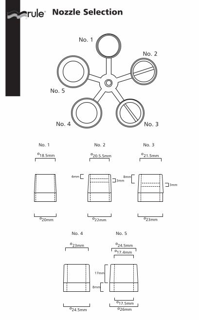
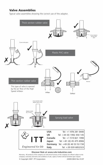
Valve AssembliesTypical valve assemblies showing the correct use of the adaptor.
Thick section rubber valve
Sprung load valve
Plastic PVC valve
Thin section rubber valve
This type of valve is openedby the air flow of the HighSpeed Inflator
High Speed Inflator/Deflator
Operating InstructionsIf these simple instructions are followed then your High Speed Inflator / Deflator will take thehassle out of inflating and deflating your dinghy for many years to come.
1. Make sure the correct adaptor is selected to suit your valve (see diagrams showing typicalvalve assemblies). Failure to use the correct adaptor will reduce performance and createback pressure which causes unwanted heat.
2. Insert adaptor into inflate / deflate port of the High Speed Inflator.3. Ensure your battery is in good condition and has a sufficient capacity of 45 AH minimum.4. Uncoil cable, connect the red (+) battery clip to the positive terminal and the black
(-) battery clip to the negative terminal.5. Fully engage the adaptor into the dinghy valve and completely depress the switch.
SafetyIf the Inflator is connected to a circuit using connections other than the battery clipssupplied the connecting fuses should be rated at 25 amps at 12 volts DC. Cigar lightersockets are NOT suitable.
Do not try to over-inflate the dinghy. The High Speed Inflator will give between 0.18 and0.21 bar (2.6 and 3.0 p.s.i.), which is suitable in most instances. If extra pressure is required,top up with a manual pump.
When maximum inflation / deflation is reached you will note a change of tone. If the unit isleft running after the tone change no more pressure will be achieved and the air retained inthe pump chamber will heat rapidly. The temperature sensitive air release valve will open,releasing the hot air and protecting the unit from over heating. However, it will not protectthe unit indefinitely and the unit should be switched off immediately the change of tone isheard and the release valve starts to vent air. On cooling the air release valve will reset.
The inflator should not be placed bottom down on a surface when operating as the airrelease valve will not function.
The lead can be extended to 20 ft (6 m) without significantly affecting performance. The minimal cross sectional area of the extending cable should be 10 AWG copper wire(2.5mm2). For longer extensions the cable should be 8 AWG copper wire (4.0mm2)minimum.
● Store away from excessive heat and direct sunlight to avoid external damage. ● If thepump fails to perform, check for blockages, air leaks and correct electrical and adaptorconnections. ● Unwrap cables fully before use. ● Do NOT secure in ‘ON’ position - handoperation only. ● Do NOT immerse in water. ●
Features● Rapid inflation and deflation of all inflatables.● Inflates a four man dinghy in 1 to 2 minutes.● Deflates, removing every last ounce of air for easy storage.● Adjustable nozzles for all inflatables and valve types.● Light weight and easy to use.● Easier and faster than manual pumps.● Temperature sensitive air release valve protects from overheating and
over inflating.● Robust long life construction.
Valve Assemblies
Note: Al desinflar botes neumáticos con válvulas A7 o B7 la parte central de la válvulapuede cerrarse estando en la posición abierta apretando fuerte y girando en sentidocontrario a las agujas del reloj.
Avon (modelo muy antiguo) A7 A
Avon (modelo antiguo) A7 C 2
Avon (modelo nuevo) B7 C 2
Bombard Válvula pequeña 17.5,mm ID (inflar) H
Válvula grande integrada D 3
Compass Válvula grande integrada D 3
Delta A7 o B7 C 2
Force Four D 3
Humber B7 C 2
Maxxon Inflar F 5
Desinflar B 1
OMC Express Modelo antiguo A
Modelo nuevo (integrada) D 3
Quicksilver A
Ribcraft A7 o B7 C 2
Ribtech A7 o B7 C 2
Tornado A7 o B7 C 2
Tinker A5 (modelo antiguo) A
B7 o C7 C 2
Valiant C 2
Zenith G
Zodiac Válvula pequeña 17,5mm ID (Inflar) A
Válvula grande integrada D 3
Colchones de aire e hincha- J
bles de PVC pequeños, etc.
Fabricante Tipo de la Válvula Diagrama Inyector
Selección del adaptador apropiado
Especificaciones
A D V E R T E N C I ASi conecta este producto a la batería de una embarcación o un coche nolo encienda y ponga en marcha el motor. La unidad está diseñada paraoperar a 12 -12,7 voltios. Si se pone en marcha el motor el voltajepuede subir a 14-15 voltios, lo que puede dañar seriamente la bombade inflado y la garantía no lo cubrirá. Además, los cables puedenenredarse en la correa del ventilador y causar daños personales ymateriales.
iD20 550 lpm 0.18 bar/min 25 máx. 12 750g
Longitud del cable: 3 metros. Equipado con pinzas de batería.
Modelo Caudal de aire Presión Amperios Voltios Peso
Diagram A
Diagram B
Diagram C
Diagram D
Diagram E
Diagram F
Diagram G
Diagram H
Diagram J
Note: When deflating dinghies with A7 or B7 valves the centre section of the valve canbe locked in the open position by pushing fully in and turning anti-clockwise.
Avon (very old type) A7 A
Avon (old type) A7 C 2
Avon (new type) B7 C 2
Bombard Small valve 17.5mm I.D. (inflate) H
Large recessed D 3
Compass Large Recessed valve D 3
Delta A7 or B7 C 2
Force Four D 3
Humber B7 C 2
Maxxon Inflate F 5
Deflate B 1
OMC Express Old type valve A
New type valve(recessed) D 3
Quicksilver A
Ribcraft A7 or B7 C 2
Ribtech A7 or B7 C 2
Tornado A7 or B7 C 2
Tinker A5 old type valve A
B7 or C7 C 2
Valiant C 2
Zenith G
Zodiac Small valve 17.5mm I.D. (Inflate) A
Large recessed D 3
Small PVC Inflatables J
and Airbeds etc.
Manufacturer Valve Type Diagram Nozzle
Selecting the correct adaptor
Specifications
W A R N I N GWhen powering this product from a car or a boat battery do not switch‘on’ and run the engine. The unit is designed to operate at 12 to 12.7volts. If the engine is switched on the voltage could rise to 14 -15 volts,which will seriously damage the Inflator and the warranty will bedisclaimed. The leads could also entangle in the fan belt and causepersonal and property damage.
iD20 20 ft/min3 2.6 psi/min 25 max. 12 1.6lbs
550 lpm 0.18 bar/min 750grms
Cable length 3 metres (10ft). Fitted with battery clips.
Model Airflow Pressure Amps Volts Weight
Bomba de inflado / desinflado de alta velocidad
Instrucciones de uso Siguiendo estas simples instrucciones conseguirá que su Bomba de Inflado / Desinflado de AltaVelocidad infle y desinfle su bote neumático sin problemas durante muchos años.1. Asegúrese de utilizar un adaptador apropiado para su válvula (ver diagramas de las válvulas
más típicas). El uso de adaptadores inadecuados afecta al funcionamiento y crea unacontrapresión que provoca un calor indeseado.
2. Inserte el adaptador en el puerto de inflado / desinflado de la Bomba de Inflado de Alta Velocidad.
3. Compruebe que la batería esté en buen estado y que tenga una capacidad mínima de 45 AH.4. Desenrolle el cable, conecte la pinza roja (+) de la batería al terminal positivo y la pinza
negra (-) al terminal negativo.5. Encajar completamente el adaptador en la válvula del bote neumático y apretar el interruptor.
SeguridadEn caso de que la conexión de la bomba de inflado a un circuito se realice utilizandoconexiones diferentes a las pinzas proporcionadas, los fusibles de conexión deben ser de 25AMPS y 12 V DC. NO utilizar la toma de corriente del encendedor del coche.
No inflar el bote neumático en exceso. La Bomba de Inflado de Alta Velocidad proporciona unapresión de 0,18 – 0,21 bar (2,6 y 3,0 libras /pulgada cuadrara), que resulta suficiente en lamayoría de los casos. En caso de necesitar más presión, utilizar una bomba manual.
Al llegar al inflado / desinflado máximo, notará un cambio de sonido. Si continúa utilizando launidad tras producirse el cambio de sonido, no conseguirá más presión y el aire retenido en lacámara de la bomba se calentará rápidamente. La válvula de escape de aire sensible a latemperatura se abrirá, expulsando el aire caliente y evitando el sobrecalentamiento de launidad. No obstante, no protegerá a la unidad indefinidamente, por lo que la unidad deberáapagarse inmediatamente después de que se oiga el cambio de sonido y que la válvula deescape empiece a expulsar aire. Tras enfriarse, la válvula de escape de aire se restaurará.
La bomba de inflado no debe colocarse boca abajo en una superficie cuando esté enfuncionamiento, ya que la válvula de escape de aire no funcionará.
El cable puede extenderse hasta 20 pies (6 metros) sin que afecte su funcionamiento se veaafectado. El área transversal mínima del alambre de cobre del alargo debe ser de 10 AWG(2,5mm2). Para mayores extensiones el alambre de cobre del cable debe ser de 8 AWG(4,0mm2) como mínimo.● Para evitar daños externos, almacene la bomba en un lugar alejado del calor excesivo y de laluz solar directa. ● En caso de que la bomba deje de funcionar, compruebe si se han producidoobstrucciones, fugas de aire y si las conexiones eléctricas y del adaptador son correctas. ●Desenrolle completamente los cables antes de su uso. ● NO deje la posición “ON” fija – sóloaccionamiento manual. ● NO sumerja la bomba en agua. ●
Características● Inflado y desinflado rápido de todo tipo de artículos hinchables.● Infla un bote neumático de cuatro personas en 1-2 minutos.● Desinfla, extrayendo completamente el aire para facilitar el almacenamiento.● Boquillas ajustables para todo tipo de válvulas y artículos hinchables.● Ligera y fácil de usar.● Más rápida y fácil que las bombas manuales.● La válvula de escape de aire sensible a la temperatura protege del
sobrecalentamiento y del inflado excesivo.● Estructura resistente y duradera.
High Speed Inflator/Deflator
Operating InstructionsIf these simple instructions are followed then your High Speed Inflator / Deflator will take thehassle out of inflating and deflating your dinghy for many years to come.
1. Make sure the correct adaptor is selected to suit your valve (see diagrams showing typicalvalve assemblies). Failure to use the correct adaptor will reduce performance and createback pressure which causes unwanted heat.
2. Insert adaptor into inflate / deflate port of the High Speed Inflator.3. Ensure your battery is in good condition and has a sufficient capacity of 45 AH minimum.4. Uncoil cable, connect the red (+) battery clip to the positive terminal and the black
(-) battery clip to the negative terminal.5. Fully engage the adaptor into the dinghy valve and completely depress the switch.
SafetyIf the Inflator is connected to a circuit using connections other than the battery clipssupplied the connecting fuses should be rated at 25 amps at 12 volts DC. Cigar lightersockets are NOT suitable.
Do not try to over-inflate the dinghy. The High Speed Inflator will give between 0.18 and0.21 bar (2.6 and 3.0 p.s.i.), which is suitable in most instances. If extra pressure is required,top up with a manual pump.
When maximum inflation / deflation is reached you will note a change of tone. If the unit isleft running after the tone change no more pressure will be achieved and the air retained inthe pump chamber will heat rapidly. The temperature sensitive air release valve will open,releasing the hot air and protecting the unit from over heating. However, it will not protectthe unit indefinitely and the unit should be switched off immediately the change of tone isheard and the release valve starts to vent air. On cooling the air release valve will reset.
The inflator should not be placed bottom down on a surface when operating as the airrelease valve will not function.
The lead can be extended to 20 ft (6 m) without significantly affecting performance. The minimal cross sectional area of the extending cable should be 10 AWG copper wire(2.5mm2). For longer extensions the cable should be 8 AWG copper wire (4.0mm2)minimum.
● Store away from excessive heat and direct sunlight to avoid external damage. ● If thepump fails to perform, check for blockages, air leaks and correct electrical and adaptorconnections. ● Unwrap cables fully before use. ● Do NOT secure in ‘ON’ position - handoperation only. ● Do NOT immerse in water. ●
Features● Rapid inflation and deflation of all inflatables.● Inflates a four man dinghy in 1 to 2 minutes.● Deflates, removing every last ounce of air for easy storage.● Adjustable nozzles for all inflatables and valve types.● Light weight and easy to use.● Easier and faster than manual pumps.● Temperature sensitive air release valve protects from overheating and
over inflating.● Robust long life construction.
Valve Assemblies
Note: Al desinflar botes neumáticos con válvulas A7 o B7 la parte central de la válvulapuede cerrarse estando en la posición abierta apretando fuerte y girando en sentidocontrario a las agujas del reloj.
Avon (modelo muy antiguo) A7 A
Avon (modelo antiguo) A7 C 2
Avon (modelo nuevo) B7 C 2
Bombard Válvula pequeña 17.5,mm ID (inflar) H
Válvula grande integrada D 3
Compass Válvula grande integrada D 3
Delta A7 o B7 C 2
Force Four D 3
Humber B7 C 2
Maxxon Inflar F 5
Desinflar B 1
OMC Express Modelo antiguo A
Modelo nuevo (integrada) D 3
Quicksilver A
Ribcraft A7 o B7 C 2
Ribtech A7 o B7 C 2
Tornado A7 o B7 C 2
Tinker A5 (modelo antiguo) A
B7 o C7 C 2
Valiant C 2
Zenith G
Zodiac Válvula pequeña 17,5mm ID (Inflar) A
Válvula grande integrada D 3
Colchones de aire e hincha- J
bles de PVC pequeños, etc.
Fabricante Tipo de la Válvula Diagrama Inyector
Selección del adaptador apropiado
Especificaciones
A D V E R T E N C I ASi conecta este producto a la batería de una embarcación o un coche nolo encienda y ponga en marcha el motor. La unidad está diseñada paraoperar a 12 -12,7 voltios. Si se pone en marcha el motor el voltajepuede subir a 14-15 voltios, lo que puede dañar seriamente la bombade inflado y la garantía no lo cubrirá. Además, los cables puedenenredarse en la correa del ventilador y causar daños personales ymateriales.
iD20 550 lpm 0.18 bar/min 25 máx. 12 750g
Longitud del cable: 3 metros. Equipado con pinzas de batería.
Modelo Caudal de aire Presión Amperios Voltios Peso
Diagram A
Diagram B
Diagram C
Diagram D
Diagram E
Diagram F
Diagram G
Diagram H
Diagram J
Gonfleur / dégonfleur rapide
Notice d’utilisationSi vous suivez de manière appropriée ces instructions, votre gonfleur/dégonfleur rapide vousaidera à gonfler et à dégonfler sans problèmes votre canot pneumatique pendant des années!1. Veillez à utiliser l’adaptateur adéquat à la valve (voir les diagrammes présentant les
assemblages de valves standards). Si vous n’utilisez pas l’adaptateur approprié, la performance sera moindre et une pression de retour sera créée provoquant une surchauffe.
2. Insérez l’adaptateur dans l’embout de gonflage/dégonflage du gonfleur rapide.3. Vérifiez le bon état de votre batterie et qu’elle dispose d’une capacité minimum de 45 Ah.4. Déroulez le câble, branchez la pince de batterie rouge (+) sur la borne positive et la
pince de batterie noire (-) sur la borne négative.5. Insérez entièrement l’adaptateur dans la valve du canot pneumatique et enfoncez
entièrement le connecteur.
SécuritéSi le gonfleur est branché sur un circuit avec des connexions autres que les pinces de batteriefournies, veillez à ce que les fusibles de connexion soient de 25 ampères à 12 volts CC. Un allume-cigare n’est pas adéquat.
Ne pas surgonfler le canot. Le gonfleur rapide produira une pression comprise entre 0,18 et0,21 bar (2,6 et 3,0 psi), qui convient dans la majorité des cas. Si une pression supérieure estrequise, complétez avec une pompe à main.
Lorsque le gonflage/dégonflage maximum est atteint, vous remarquerez un changement dans lebruit produit par le gonfleur. Si l’appareil est toujours en marche après le changement de cebruit, aucune pression supplémentaire ne se produira et l’air retenu dans la chambre de lapompe chauffera rapidement. Une soupape thermique de compensation s’ouvrira, relâchant del’air chaud et protégeant de ce fait l’appareil contre la surchauffe. Toutefois, elle ne protégerapas indéfiniment l’appareil et celui-ci devra être immédiatement éteint. Le changement de tondu gonflage se fera instantanément entendre et la soupape commencera à dégager l’air. Lors durefroidissement, la soupape reviendra à son point initial.
Le gonfleur ne doit pas être posé en marche à l’envers sur une surface car la soupape thermiquene fonctionnera pas.
Il est possible d’étendre le câble jusqu’à 6 mètres sans nuire à la performance de l’appareil. Si vous devez utiliser une rallonge pour alimenter le gonfleur, la section des fils doit être de4mm2 minimum.● Stocker à l’abri de la chaleur excessive et de la lumière directe du soleil, pour éviterd’endommager l’extérieur. ● Si la pompe ne fonctionne pas, rechercher les éventuellesobstructions (y compris le filtre) et fuites d’air et vérifier si les connexions électriques etl’adaptateur sont correctes. ● Dévider complètement les câbles avant d’utiliser la pompe. ●NE PAS bloquer en position de marche - fonctionnement manuel uniquement. ● NE PASimmerger dans l’eau. ●
Features● Gonflage et dégonflage rapides de tous articles gonflables.● Gonfle un canot pneumatique quatre personnes en 1 à 2 minutes.● Dégonfle et aspire complètement l’air pour faciliter le rangement.● Embouts divers pour tous les types d’articles gonflables et de valves.● Léger et simple d’utilisation.● Plus facile et plus rapide que les pompes manuelles.● Une soupape thermique de compensation protège contre la surchauffe et
la sur gonflage.● Construction robuste et durable.
OBS: Vid tömning av gummibåtar med A7 eller B7-ventiler kan ventilens mittsektionlåsas i öppet läge genom att trycka inåt och vrida moturs.
Avon (mycket gammal typ) A7 A
Avon (gammal typ) A7 C 2
Avon (ny typ) B7 C 2
Bombard Liten ventil 17,5mm inner diam. (uppblåsning) H
Stor infälld 3
Compass Stor infälld ventil D 3
Delta A7 eller B7 C 2
Force Four D 3
Humber B7 C 2
Maxxon Uppblåsning F 5
Tömning B 1
OMC Express Gammal ventiltyp A
Ny ventiltyp (infälld) D 3
Quicksilver A
Ribcraft A7 eller B7 C 2
Ribtech A7 eller B7 C 2
Tornado A7 ellerB7 C 2
Tinker A5 gammal ventiltyp A
B7 eller C7 C 2
Valiant C 2
Zenith G
Zodiac Liten ventil 17,5mm inner diam. (uppblåsning) A
Stor infälld D 3
Små gummibåtar av PVC J
och luftmadrasser osv.
Producent Ventiltyp Diagram Dysa
Så här väljer du rätt adapter
Specifikationer
V A R N I N G !När kraften hämtas från ett bil- eller båtbatteri, vrid inte omtändningen och starta motorn. Pumpen är konstruerad för att drivasmed 12 till 12,7 volt. Om motorn startas kan spänningen stiga till 14-15volt, vilket ger allvarliga skador på pumpen som inte ersätts avgarantin. Kablarna kan även fastna i fläktremmen och orsaka person-eller egendomsskada.
iD20 20 fot/min3 2,6 psi/min 25 max. 12 1,6lbs
550 lpm 0,18 bar/min 750g
Kabellängd 3 meter (10 fot). Monterad med batteriklämmor.
Modell Luftströmning Arbetstryck Ampere Volt Vikt
Reversibel Tryckluftspump
BruksanvisningFölj dessa enkla instruktioner för att undvika krångel med uppblåsning och tömning av dingummibåt i många år framöver tack vare tryckluftspumpen.
1. Kontrollera att du valt rätt adapter som passar ventilen (se tabellen för vanliga ventiltyper).Om du inte använder rätt adapter minskas effektiviteten och ett mottryck bildas som geroönskad friktion.
2. Sätt adaptern i tryckluftspumpens öppning för uppblåsning/tömning. 3. Kontrollera att batteriet är i god kondition och har tillräcklig kapacitet med minst 45 Ah.4. Linda av sladden och anslut den röda (+) batteriklämma till pluspolen och den svarta
(-) till minuspolen.5. Tryck in adaptern helt i ventilen och tryck ner omkopplaren helt.
SäkerhetOm tryckluftspumpen ansluts till en krets på annat sätt än med de medföljande batteriklämmaska säkringarna vara 12 amp och 12V. Cigarrettändaruttag är INTE lämpliga.
Blås inte upp gummibåten för mycket. Tryckluftspumpen ger mellan 0,18 och 0,21 bar (2,6 och 3,0 PSI), vilket passar för de flesta tillfällen. Om det behövs högre tryck, fyll på med en handpump.
När maximal uppblåsning/tömning uppnåtts, ändras ljudnivån. Om man låter pumpen fortsättaefter ändrad ljudnivå, fås inget högre tryck och luften som finns inuti pumpen blir snabbtmycket varm. Den temperaturkänsliga öppningsventilen öppnar och släpper ut den varmaluften och skyddar pumpen från överhettning. Men den skyddar inte hur länge som helst ochdärför ska pumpen stängas av med detsamma den ändrade tonen hörs och tömningsventilenbörjar släppa ut luft. När luften kylts ned stängs tömningsventilen.
Pumpen får inte placeras med botten direkt på en underliggande yta när den går eftersomtömningsventilen då inte fungerar.
Kabeln kan förlängas upp till 6 m utan att det nämnvärt påverkar kapaciteten.
Minsta tvärsnittsyta på skarvsladden ska vara 10 AWG, koppar (2,5mm2).För ytterligare förlängning ska kabeln minst vara 8 AWG, koppar (4,0mm2).● Förvaras avskilt från hög värme och direkt solljus för att undvika extern skada. ● Om pumpeninte fungerar, kontrollera blockeringar (inklusive filter), läckor och korrekta elektriskaanslutningar och adapteranslutningar. ● Vira helt ut kablar (inga kabelnystan) innan pumpentas i bruk. ● Säkra INTE i läget “PÅ” – endast handdrift. ● Sänk INTE ner i vatten. ●
Egenskaper● Snabb uppblåsning eller tömning av luft av alla uppblåsbara artiklar.● Pumpar upp en fyra personers gummibåt på 1 till 2 minuter.● Tömmer ut varje gnutta luft, vilket underlättar förvaring.● Justerbara munstycken för alla uppblåsbara artiklar och typer av ventiler.● Lättviktig och enkel att använda.● Enklare och snabbare än manuella pumpar.● Temperaturkänslig luftventil skyddar från överhettning och övertryck.● Robust konstruktion.
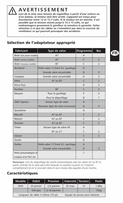
Remarque: Lors du dégonflage de canots pneumatiques avec les valves A7 ou B7 lapartie centrale de la valve peut être bloquée en position ouverte en l’insérantcomplètement et en la tournant dans le sens inverse des aiguilles d’une montre.
Avon (très ancien modéle) A7 A
Avon (ancien modéle) A7 C 2
Avon (nouveau modéle) B7 C 2
Bombard Petite valve 17,5mm D.I. (gonflage) H
Grande valve encastrable D 3
Compass Grande valve encastrable D 3
Delta A7 ou B7 C 2
Force Four D 3
Humber B7 C 2
Maxxon Pour le gonflage F 5
Pour le dégonflage B 1
OMC Express Ancien type de valve A
Nouveau type de valve (encastrée) D 3
Quicksilver A
Ribcraft A7 ou B7 C 2
Ribtech A7 ou B7 C 2
Tornado A7 ou B7 C 2
Tinker Ancien type de valve A5 A
B7 ou C7 C 2
Valiant C 2
Zenith G
Zodiac Petite valve 17,5mm D.I. (gonflage) A
Grande valve encastrable D 3
Petits pneumatiques et J
matelas d’air PVC etc.
Fabricant Type de valve Diagramme Bec
Sélection de l’adaptateur approprié
Caractéristiques
A V E R T I S S E M E N TLors de la mise sous tension de cegonfleur à partir d’une voiture oud’un bateau, le moteur doit être arrété. L’appareil est conçu pourfonctionner entre 12 et 12,7 volts. Si le moteur est en marche, il estpossible que la tension monte jusqu’à 14 à 15 volts, ce quiendommagera gravement le gonfleur et annulera la garantie. Faitesattention à ce que les câbles ne s’emmêlent pas dans la courroie duventilateur ce qui pourrait provoquer des accidents.
iD20 20 pi/min3 2,6 psi/min 25 max. 12 1,6lbs
550 lpm 0,18 bar/min 750g
Longueur de câble 3 mètres (10 pi). Equipé de pinces pour batterie.
Modèle Débit Pression Intensité Tension Poids
Reversibel Tryckluftspump
BruksanvisningFölj dessa enkla instruktioner för att undvika krångel med uppblåsning och tömning av dingummibåt i många år framöver tack vare tryckluftspumpen.
1. Kontrollera att du valt rätt adapter som passar ventilen (se tabellen för vanliga ventiltyper).Om du inte använder rätt adapter minskas effektiviteten och ett mottryck bildas som geroönskad friktion.
2. Sätt adaptern i tryckluftspumpens öppning för uppblåsning/tömning. 3. Kontrollera att batteriet är i god kondition och har tillräcklig kapacitet med minst 45 Ah.4. Linda av sladden och anslut den röda (+) batteriklämma till pluspolen och den svarta
(-) till minuspolen.5. Tryck in adaptern helt i ventilen och tryck ner omkopplaren helt.
SäkerhetOm tryckluftspumpen ansluts till en krets på annat sätt än med de medföljande batteriklämmaska säkringarna vara 12 amp och 12V. Cigarrettändaruttag är INTE lämpliga.
Blås inte upp gummibåten för mycket. Tryckluftspumpen ger mellan 0,18 och 0,21 bar (2,6 och 3,0 PSI), vilket passar för de flesta tillfällen. Om det behövs högre tryck, fyll på med en handpump.
När maximal uppblåsning/tömning uppnåtts, ändras ljudnivån. Om man låter pumpen fortsättaefter ändrad ljudnivå, fås inget högre tryck och luften som finns inuti pumpen blir snabbtmycket varm. Den temperaturkänsliga öppningsventilen öppnar och släpper ut den varmaluften och skyddar pumpen från överhettning. Men den skyddar inte hur länge som helst ochdärför ska pumpen stängas av med detsamma den ändrade tonen hörs och tömningsventilenbörjar släppa ut luft. När luften kylts ned stängs tömningsventilen.
Pumpen får inte placeras med botten direkt på en underliggande yta när den går eftersomtömningsventilen då inte fungerar.
Kabeln kan förlängas upp till 6 m utan att det nämnvärt påverkar kapaciteten.
Minsta tvärsnittsyta på skarvsladden ska vara 10 AWG, koppar (2,5mm2).För ytterligare förlängning ska kabeln minst vara 8 AWG, koppar (4,0mm2).● Förvaras avskilt från hög värme och direkt solljus för att undvika extern skada. ● Om pumpeninte fungerar, kontrollera blockeringar (inklusive filter), läckor och korrekta elektriskaanslutningar och adapteranslutningar. ● Vira helt ut kablar (inga kabelnystan) innan pumpentas i bruk. ● Säkra INTE i läget “PÅ” – endast handdrift. ● Sänk INTE ner i vatten. ●
Egenskaper● Snabb uppblåsning eller tömning av luft av alla uppblåsbara artiklar.● Pumpar upp en fyra personers gummibåt på 1 till 2 minuter.● Tömmer ut varje gnutta luft, vilket underlättar förvaring.● Justerbara munstycken för alla uppblåsbara artiklar och typer av ventiler.● Lättviktig och enkel att använda.● Enklare och snabbare än manuella pumpar.● Temperaturkänslig luftventil skyddar från överhettning och övertryck.● Robust konstruktion.
Remarque: Lors du dégonflage de canots pneumatiques avec les valves A7 ou B7 lapartie centrale de la valve peut être bloquée en position ouverte en l’insérantcomplètement et en la tournant dans le sens inverse des aiguilles d’une montre.
Avon (très ancien modéle) A7 A
Avon (ancien modéle) A7 C 2
Avon (nouveau modéle) B7 C 2
Bombard Petite valve 17,5mm D.I. (gonflage) H
Grande valve encastrable D 3
Compass Grande valve encastrable D 3
Delta A7 ou B7 C 2
Force Four D 3
Humber B7 C 2
Maxxon Pour le gonflage F 5
Pour le dégonflage B 1
OMC Express Ancien type de valve A
Nouveau type de valve (encastrée) D 3
Quicksilver A
Ribcraft A7 ou B7 C 2
Ribtech A7 ou B7 C 2
Tornado A7 ou B7 C 2
Tinker Ancien type de valve A5 A
B7 ou C7 C 2
Valiant C 2
Zenith G
Zodiac Petite valve 17,5mm D.I. (gonflage) A
Grande valve encastrable D 3
Petits pneumatiques et J
matelas d’air PVC etc.
Fabricant Type de valve Diagramme Bec
Sélection de l’adaptateur approprié
Caractéristiques
A V E R T I S S E M E N TLors de la mise sous tension de cegonfleur à partir d’une voiture oud’un bateau, le moteur doit être arrété. L’appareil est conçu pourfonctionner entre 12 et 12,7 volts. Si le moteur est en marche, il estpossible que la tension monte jusqu’à 14 à 15 volts, ce quiendommagera gravement le gonfleur et annulera la garantie. Faitesattention à ce que les câbles ne s’emmêlent pas dans la courroie duventilateur ce qui pourrait provoquer des accidents.
iD20 20 pi/min3 2,6 psi/min 25 max. 12 1,6lbs
550 lpm 0,18 bar/min 750g
Longueur de câble 3 mètres (10 pi). Equipé de pinces pour batterie.
Modèle Débit Pression Intensité Tension Poids
Gonfleur / dégonfleur rapide
Notice d’utilisationSi vous suivez de manière appropriée ces instructions, votre gonfleur/dégonfleur rapide vousaidera à gonfler et à dégonfler sans problèmes votre canot pneumatique pendant des années!1. Veillez à utiliser l’adaptateur adéquat à la valve (voir les diagrammes présentant les
assemblages de valves standards). Si vous n’utilisez pas l’adaptateur approprié, la performance sera moindre et une pression de retour sera créée provoquant une surchauffe.
2. Insérez l’adaptateur dans l’embout de gonflage/dégonflage du gonfleur rapide.3. Vérifiez le bon état de votre batterie et qu’elle dispose d’une capacité minimum de 45 Ah.4. Déroulez le câble, branchez la pince de batterie rouge (+) sur la borne positive et la
pince de batterie noire (-) sur la borne négative.5. Insérez entièrement l’adaptateur dans la valve du canot pneumatique et enfoncez
entièrement le connecteur.
SécuritéSi le gonfleur est branché sur un circuit avec des connexions autres que les pinces de batteriefournies, veillez à ce que les fusibles de connexion soient de 25 ampères à 12 volts CC. Un allume-cigare n’est pas adéquat.
Ne pas surgonfler le canot. Le gonfleur rapide produira une pression comprise entre 0,18 et0,21 bar (2,6 et 3,0 psi), qui convient dans la majorité des cas. Si une pression supérieure estrequise, complétez avec une pompe à main.
Lorsque le gonflage/dégonflage maximum est atteint, vous remarquerez un changement dans lebruit produit par le gonfleur. Si l’appareil est toujours en marche après le changement de cebruit, aucune pression supplémentaire ne se produira et l’air retenu dans la chambre de lapompe chauffera rapidement. Une soupape thermique de compensation s’ouvrira, relâchant del’air chaud et protégeant de ce fait l’appareil contre la surchauffe. Toutefois, elle ne protégerapas indéfiniment l’appareil et celui-ci devra être immédiatement éteint. Le changement de tondu gonflage se fera instantanément entendre et la soupape commencera à dégager l’air. Lors durefroidissement, la soupape reviendra à son point initial.
Le gonfleur ne doit pas être posé en marche à l’envers sur une surface car la soupape thermiquene fonctionnera pas.
Il est possible d’étendre le câble jusqu’à 6 mètres sans nuire à la performance de l’appareil. Si vous devez utiliser une rallonge pour alimenter le gonfleur, la section des fils doit être de4mm2 minimum.● Stocker à l’abri de la chaleur excessive et de la lumière directe du soleil, pour éviterd’endommager l’extérieur. ● Si la pompe ne fonctionne pas, rechercher les éventuellesobstructions (y compris le filtre) et fuites d’air et vérifier si les connexions électriques etl’adaptateur sont correctes. ● Dévider complètement les câbles avant d’utiliser la pompe. ●NE PAS bloquer en position de marche - fonctionnement manuel uniquement. ● NE PASimmerger dans l’eau. ●
Features● Gonflage et dégonflage rapides de tous articles gonflables.● Gonfle un canot pneumatique quatre personnes en 1 à 2 minutes.● Dégonfle et aspire complètement l’air pour faciliter le rangement.● Embouts divers pour tous les types d’articles gonflables et de valves.● Léger et simple d’utilisation.● Plus facile et plus rapide que les pompes manuelles.● Une soupape thermique de compensation protège contre la surchauffe et
la sur gonflage.● Construction robuste et durable.
OBS: Vid tömning av gummibåtar med A7 eller B7-ventiler kan ventilens mittsektionlåsas i öppet läge genom att trycka inåt och vrida moturs.
Avon (mycket gammal typ) A7 A
Avon (gammal typ) A7 C 2
Avon (ny typ) B7 C 2
Bombard Liten ventil 17,5mm inner diam. (uppblåsning) H
Stor infälld 3
Compass Stor infälld ventil D 3
Delta A7 eller B7 C 2
Force Four D 3
Humber B7 C 2
Maxxon Uppblåsning F 5
Tömning B 1
OMC Express Gammal ventiltyp A
Ny ventiltyp (infälld) D 3
Quicksilver A
Ribcraft A7 eller B7 C 2
Ribtech A7 eller B7 C 2
Tornado A7 ellerB7 C 2
Tinker A5 gammal ventiltyp A
B7 eller C7 C 2
Valiant C 2
Zenith G
Zodiac Liten ventil 17,5mm inner diam. (uppblåsning) A
Stor infälld D 3
Små gummibåtar av PVC J
och luftmadrasser osv.
Producent Ventiltyp Diagram Dysa
Så här väljer du rätt adapter
Specifikationer
V A R N I N G !När kraften hämtas från ett bil- eller båtbatteri, vrid inte omtändningen och starta motorn. Pumpen är konstruerad för att drivasmed 12 till 12,7 volt. Om motorn startas kan spänningen stiga till 14-15volt, vilket ger allvarliga skador på pumpen som inte ersätts avgarantin. Kablarna kan även fastna i fläktremmen och orsaka person-eller egendomsskada.
iD20 20 fot/min3 2,6 psi/min 25 max. 12 1,6lbs
550 lpm 0,18 bar/min 750g
Kabellängd 3 meter (10 fot). Monterad med batteriklämmor.
Modell Luftströmning Arbetstryck Ampere Volt Vikt
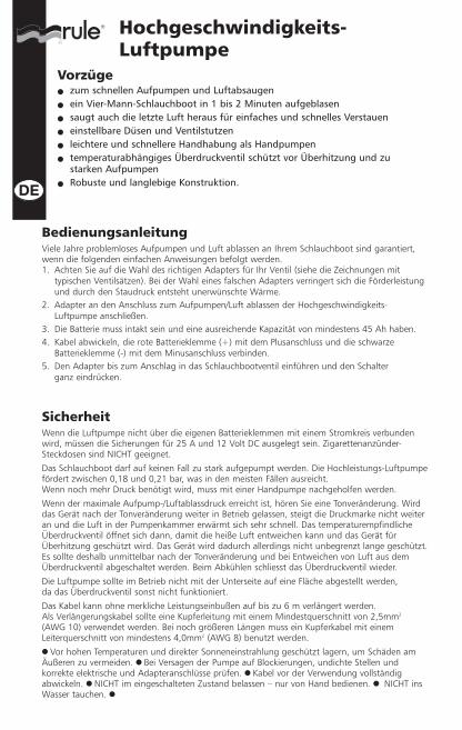
Hochgeschwindigkeits-Luftpumpe
BedienungsanleitungViele Jahre problemloses Aufpumpen und Luft ablassen an Ihrem Schlauchboot sind garantiert,wenn die folgenden einfachen Anweisungen befolgt werden.1. Achten Sie auf die Wahl des richtigen Adapters für Ihr Ventil (siehe die Zeichnungen mit
typischen Ventilsätzen). Bei der Wahl eines falschen Adapters verringert sich die Förderleistungund durch den Staudruck entsteht unerwünschte Wärme.
2. Adapter an den Anschluss zum Aufpumpen/Luft ablassen der Hochgeschwindigkeits-Luftpumpe anschließen.
3. Die Batterie muss intakt sein und eine ausreichende Kapazität von mindestens 45 Ah haben.4. Kabel abwickeln, die rote Batterieklemme (+) mit dem Plusanschluss und die schwarze
Batterieklemme (-) mit dem Minusanschluss verbinden.5. Den Adapter bis zum Anschlag in das Schlauchbootventil einführen und den Schalter
ganz eindrücken.
SicherheitWenn die Luftpumpe nicht über die eigenen Batterieklemmen mit einem Stromkreis verbundenwird, müssen die Sicherungen für 25 A und 12 Volt DC ausgelegt sein. Zigarettenanzünder-Steckdosen sind NICHT geeignet.
Das Schlauchboot darf auf keinen Fall zu stark aufgepumpt werden. Die Hochleistungs-Luftpumpefördert zwischen 0,18 und 0,21 bar, was in den meisten Fällen ausreicht. Wenn noch mehr Druck benötigt wird, muss mit einer Handpumpe nachgeholfen werden.
Wenn der maximale Aufpump-/Luftablassdruck erreicht ist, hören Sie eine Tonveränderung. Wirddas Gerät nach der Tonveränderung weiter in Betrieb gelassen, steigt die Druckmarke nicht weiteran und die Luft in der Pumpenkammer erwärmt sich sehr schnell. Das temperaturempfindlicheÜberdruckventil öffnet sich dann, damit die heiße Luft entweichen kann und das Gerät fürÜberhitzung geschützt wird. Das Gerät wird dadurch allerdings nicht unbegrenzt lange geschützt.Es sollte deshalb unmittelbar nach der Tonveränderung und bei Entweichen von Luft aus demÜberdruckventil abgeschaltet werden. Beim Abkühlen schliesst das Überdruckventil wieder.
Die Luftpumpe sollte im Betrieb nicht mit der Unterseite auf eine Fläche abgestellt werden, da das Überdruckventil sonst nicht funktioniert.
Das Kabel kann ohne merkliche Leistungseinbußen auf bis zu 6 m verlängert werden. Als Verlängerungskabel sollte eine Kupferleitung mit einem Mindestquerschnitt von 2,5mm2
(AWG 10) verwendet werden. Bei noch größeren Längen muss ein Kupferkabel mit einemLeiterquerschnitt von mindestens 4,0mm2 (AWG 8) benutzt werden.● Vor hohen Temperaturen und direkter Sonneneinstrahlung geschützt lagern, um Schäden amÄußeren zu vermeiden. ● Bei Versagen der Pumpe auf Blockierungen, undichte Stellen undkorrekte elektrische und Adapteranschlüsse prüfen. ● Kabel vor der Verwendung vollständigabwickeln. ● NICHT im eingeschalteten Zustand belassen – nur von Hand bedienen. ● NICHT insWasser tauchen. ●
Vorzüge● zum schnellen Aufpumpen und Luftabsaugen● ein Vier-Mann-Schlauchboot in 1 bis 2 Minuten aufgeblasen● saugt auch die letzte Luft heraus für einfaches und schnelles Verstauen● einstellbare Düsen und Ventilstutzen● leichtere und schnellere Handhabung als Handpumpen● temperaturabhängiges Überdruckventil schützt vor Überhitzung und zu
starken Aufpumpen● Robuste und langlebige Konstruktion.
Opmerking: Tijdens het leeg laten lopen van rubberboten met A7 of B7 ventielen, kanhet middenstuk van het ventiel in de open stand worden vergrendeld door het ventielvolledig naar binnen te duwen en naar links te draaien.
Keuze van de juiste adapter
Specificaties
W A A R S C H U W I N GAls de pomp door de accu van een auto of boot wordt aangedreven,dan mag de motor van de auto of boot niet in werking worden gesteldof draaien. De pomp werd ontworpen om op 12 tot 12,7 Volt tedraaien. Als de motor wordt ingeschakeld dan kan het voltage stijgentot 14-15 Volt en de luchtpomp ernstig beschadigen waardoor u geenaanspraak kunt maken op de garantie. De kabels kunnen ook verstriktraken in de V-riem en lichamelijk letsel en materiële schadeveroorzaken.
iD20 20 ft/min3 2,6 psi/min 25 max. 12 1,6lbs
550 lpm 0,18 bar/min 750g
Kabellengte 3 meter (10ft). Bevestiging met accuklemmen.
Model Luchtstroom Druk Amp Volt Gewichtdebiet
Avon (zeer oud type) A7 A
Avon (oud type) A7 C 2
Avon (nieuw type) B7 C 2
Bombard Klein ventiel, 17,5mm inwendige diameter (opblaasventiel) H
Groot ingebouwd D 3
Compass Groot ingebouwd ventiel D 3
Delta A7 of B7 C 2
Force Four D 3
Humber B7 C 2
Maxxon Opblaasventiel F 5
Ontluchtventiel B 1
OMC Express Oud type ventiel A
Nieuw type ventiel (ingebouwd) D 3
Quicksilver A
Ribcraft A7 of B7 C 2
Ribtech A7 of B7 C 2
Tornado A7 of B7 C 2
Tinker A5 oud type ventiel A
B7 of C7 C 2
Valiant C 2
Zenith G
Zodiac Klein ventiel, 17,5mm inwendige diameter (opblaasventiel) A
Groot ingebouwd D 3
Kleine PVC opblassarti- J
kelen en luchtbedden etc.
Fabrikant Het Type Van Kelp Diagram Pisp
Brochure Luchtpomp
GebruiksaanwijzingDoor het volgen van deze simpele voorschriften zorgt uw hoge snelheid lucht/ontluchtingspomp,gedurende vele jaren voor het probleemloos opblazen en leeg zuigen van o.a. uw rubberboot. 1. Kies de juiste adapter die op uw ventiel past (zie de schema’s die standaard
ventielconfiguraties weergeven). Het nalaten om de juiste adapter te gebruiken, vermindert de prestatie en veroorzaakt tegendruk die ongewenste warmte produceert.
2. Steek de adapter in de pers-/zuigpoort van de luchtpomp.3. Controleer of uw accu in goede staat verkeert en een minimale capaciteit van 45 AH levert. 4. Rol de kabel af, bevestig de rode (+) accuklem op de positieve pool en de zwarte (-)
accuklem op de negatieve pool.5. Duw de adapter volledig in het ventiel van de rubberboot en druk de schakelaar volledig in.
VeiligheidDe zekeringen moeten een nominaal vermogen van 25 ampère bij 12 Volt gelijkstroom leverenals de luchtpomp is aangesloten op een circuit dat andere aansluitingen gebruikt dan de meegeleverde accuklemmen. Het contact van de sigarettenaansteker kan NIET worden gebruikt.
Probeer niet om de rubberboot te hard op te pompen. De hoge snelheid lucht-/ontluchtpomplevert een druk tussen 0,18 en 0,21 bar (2,6 en 3,0 psi), die in de meeste gevallen voldoet.Gebruik een handpomp als aanvullende druk is vereist.
U hoort een toonverandering zodra de rubberboot volledig is opgeblazen / leeg gelopen. Als u de pomp laat draaien na de toonverandering wordt er geen druk meer opgebouwd enwordt de lucht in de pompkamer snel verwarmd. Het temperatuurgevoelige ontluchtingventielwordt geopend, voert de hete lucht af en beschermt de pomp tegen oververhitting. De pompwordt echter niet gedurende onbepaalde tijd beschermd en de pomp moet onmiddellijk wordenuitgeschakeld na de toonverandering en hierna begint het ontluchtingventiel met het ontluchten.Het ontluchtventiel wordt na het afkoelen gereset.
De luchtpomp mag niet met de onderkant naar beneden op een oppervlak worden geplaatsttijdens het gebruik aangezien het ontluchtingventiel dan niet werkt.
De kabel kan tot 20 voet (6 meter) worden verlengd zonder afbreuk te doen aan de prestatie. De minimale dwarsdoorsnede van de verloopkabel moet 10 AWG koperdraad (2,5mm2) zijn. Bij gebruik van langere verloopkabels moet de kabel minstens een 8 AWG koperdraad (4,0mm2) zijn.● Vermijd bij opbergen, hitte en directe zonlicht. Dit om externe schade te voorkomen. ● Als depomp niet goed presteert, controleer dan op verstoppingen, lekkage van lucht en juisteelektrische- en adapteraansluitingen. ● Kabels zorgvuldig loswikkelen voor gebruik. ● NIETzekeren in de positie ‘ON’ – alleen in handoperatie. ● NIET in contact met water of anderevloeistoffen brengen. ●
Kenmerken● Voor snel opblazen en leegzuigen van alle soorten opblaasboten.● Opblazen van rubberboot voor vier personen binnen 1 tot 2 minuten tijd.● Door het leegzuigen van het laatste “zuchtje” lucht, laat uw opblaasboot of
luchtbed zich ideaal opvouwen en opbergen● Verstelbare tuiten voor alle soorten opblaasboten en ventielen.● Licht en gebruiksvriendelijk.● Gemakkelijker en sneller dan handpompen.● Temperatuurgevoelig ontluchtingsventiel als beveiliging tegen oververhitting
en te hard opblazen.● Robuuste constructie voor lange levensduur.
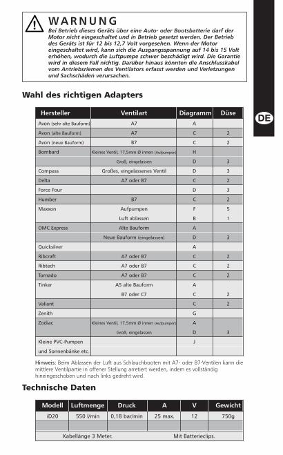
Hinweis: Beim Ablassen der Luft aus Schlauchbooten mit A7- oder B7-Ventilen kann diemittlere Ventilpartie in offener Stellung arretiert werden, indem es vollständighineingeschoben und nach links gedreht wird.
Avon (sehr alte Bauform) A7 A
Avon (alte Bauform) A7 C 2
Avon (neue Bauform) B7 C 2
Bombard Kleines Ventil, 17,5mm Ø innen (Aufpumpen) H
Groß, eingelassen D 3
Compass Großes, eingelassenes Ventil D 3
Delta A7 oder B7 C 2
Force Four D 3
Humber B7 C 2
Maxxon Aufpumpen F 5
Luft ablassen B 1
OMC Express Alte Bauform A
Neue Bauform (eingelassen) D 3
Quicksilver A
Ribcraft A7 oder B7 C 2
Ribtech A7 oder B7 C 2
Tornado A7 oder B7 C 2
Tinker A5 alte Bauform A
B7 oder C7 C 2
Valiant C 2
Zenith G
Zodiac Kleines Ventil, 17,5mm Ø innen (Aufpumpen) A
Groß, eingelassen D 3
Kleine PVC-Pumpen J
und Sonnenbänke etc.
Hersteller Ventilart Diagramm Düse
Wahl des richtigen Adapters
Technische Daten
W A R N U N GBei Betrieb dieses Geräts über eine Auto- oder Bootsbatterie darf derMotor nicht eingeschaltet und in Betrieb gesetzt werden. Der Betriebdes Geräts ist für 12 bis 12,7 Volt vorgesehen. Wenn der Motoreingeschaltet wird, kann sich die Ausgangsspannung auf 14 bis 15 Volterhöhen, wodurch die Luftpumpe schwer beschädigt wird. Die Garantiewird in diesem Fall nichtig. Darüber hinaus könnten die Anschlusskabelvom Antriebsriemen des Ventilators erfasst werden und Verletzungenund Sachschäden verursachen.
iD20 550 l/min 0,18 bar/min 25 max. 12 750g
Kabellänge 3 Meter. Mit Batterieclips.
Modell Luftmenge Druck A V Gewicht
Brochure Luchtpomp
GebruiksaanwijzingDoor het volgen van deze simpele voorschriften zorgt uw hoge snelheid lucht/ontluchtingspomp,gedurende vele jaren voor het probleemloos opblazen en leeg zuigen van o.a. uw rubberboot. 1. Kies de juiste adapter die op uw ventiel past (zie de schema’s die standaard
ventielconfiguraties weergeven). Het nalaten om de juiste adapter te gebruiken, vermindert de prestatie en veroorzaakt tegendruk die ongewenste warmte produceert.
2. Steek de adapter in de pers-/zuigpoort van de luchtpomp.3. Controleer of uw accu in goede staat verkeert en een minimale capaciteit van 45 AH levert. 4. Rol de kabel af, bevestig de rode (+) accuklem op de positieve pool en de zwarte (-)
accuklem op de negatieve pool.5. Duw de adapter volledig in het ventiel van de rubberboot en druk de schakelaar volledig in.
VeiligheidDe zekeringen moeten een nominaal vermogen van 25 ampère bij 12 Volt gelijkstroom leverenals de luchtpomp is aangesloten op een circuit dat andere aansluitingen gebruikt dan de meegeleverde accuklemmen. Het contact van de sigarettenaansteker kan NIET worden gebruikt.
Probeer niet om de rubberboot te hard op te pompen. De hoge snelheid lucht-/ontluchtpomplevert een druk tussen 0,18 en 0,21 bar (2,6 en 3,0 psi), die in de meeste gevallen voldoet.Gebruik een handpomp als aanvullende druk is vereist.
U hoort een toonverandering zodra de rubberboot volledig is opgeblazen / leeg gelopen. Als u de pomp laat draaien na de toonverandering wordt er geen druk meer opgebouwd enwordt de lucht in de pompkamer snel verwarmd. Het temperatuurgevoelige ontluchtingventielwordt geopend, voert de hete lucht af en beschermt de pomp tegen oververhitting. De pompwordt echter niet gedurende onbepaalde tijd beschermd en de pomp moet onmiddellijk wordenuitgeschakeld na de toonverandering en hierna begint het ontluchtingventiel met het ontluchten.Het ontluchtventiel wordt na het afkoelen gereset.
De luchtpomp mag niet met de onderkant naar beneden op een oppervlak worden geplaatsttijdens het gebruik aangezien het ontluchtingventiel dan niet werkt.
De kabel kan tot 20 voet (6 meter) worden verlengd zonder afbreuk te doen aan de prestatie. De minimale dwarsdoorsnede van de verloopkabel moet 10 AWG koperdraad (2,5mm2) zijn. Bij gebruik van langere verloopkabels moet de kabel minstens een 8 AWG koperdraad (4,0mm2) zijn.● Vermijd bij opbergen, hitte en directe zonlicht. Dit om externe schade te voorkomen. ● Als depomp niet goed presteert, controleer dan op verstoppingen, lekkage van lucht en juisteelektrische- en adapteraansluitingen. ● Kabels zorgvuldig loswikkelen voor gebruik. ● NIETzekeren in de positie ‘ON’ – alleen in handoperatie. ● NIET in contact met water of anderevloeistoffen brengen. ●
Kenmerken● Voor snel opblazen en leegzuigen van alle soorten opblaasboten.● Opblazen van rubberboot voor vier personen binnen 1 tot 2 minuten tijd.● Door het leegzuigen van het laatste “zuchtje” lucht, laat uw opblaasboot of
luchtbed zich ideaal opvouwen en opbergen● Verstelbare tuiten voor alle soorten opblaasboten en ventielen.● Licht en gebruiksvriendelijk.● Gemakkelijker en sneller dan handpompen.● Temperatuurgevoelig ontluchtingsventiel als beveiliging tegen oververhitting
en te hard opblazen.● Robuuste constructie voor lange levensduur.
Hinweis: Beim Ablassen der Luft aus Schlauchbooten mit A7- oder B7-Ventilen kann diemittlere Ventilpartie in offener Stellung arretiert werden, indem es vollständighineingeschoben und nach links gedreht wird.
Avon (sehr alte Bauform) A7 A
Avon (alte Bauform) A7 C 2
Avon (neue Bauform) B7 C 2
Bombard Kleines Ventil, 17,5mm Ø innen (Aufpumpen) H
Groß, eingelassen D 3
Compass Großes, eingelassenes Ventil D 3
Delta A7 oder B7 C 2
Force Four D 3
Humber B7 C 2
Maxxon Aufpumpen F 5
Luft ablassen B 1
OMC Express Alte Bauform A
Neue Bauform (eingelassen) D 3
Quicksilver A
Ribcraft A7 oder B7 C 2
Ribtech A7 oder B7 C 2
Tornado A7 oder B7 C 2
Tinker A5 alte Bauform A
B7 oder C7 C 2
Valiant C 2
Zenith G
Zodiac Kleines Ventil, 17,5mm Ø innen (Aufpumpen) A
Groß, eingelassen D 3
Kleine PVC-Pumpen J
und Sonnenbänke etc.
Hersteller Ventilart Diagramm Düse
Wahl des richtigen Adapters
Technische Daten
W A R N U N GBei Betrieb dieses Geräts über eine Auto- oder Bootsbatterie darf derMotor nicht eingeschaltet und in Betrieb gesetzt werden. Der Betriebdes Geräts ist für 12 bis 12,7 Volt vorgesehen. Wenn der Motoreingeschaltet wird, kann sich die Ausgangsspannung auf 14 bis 15 Volterhöhen, wodurch die Luftpumpe schwer beschädigt wird. Die Garantiewird in diesem Fall nichtig. Darüber hinaus könnten die Anschlusskabelvom Antriebsriemen des Ventilators erfasst werden und Verletzungenund Sachschäden verursachen.
iD20 550 l/min 0,18 bar/min 25 max. 12 750g
Kabellänge 3 Meter. Mit Batterieclips.
Modell Luftmenge Druck A V Gewicht
Hochgeschwindigkeits-Luftpumpe
BedienungsanleitungViele Jahre problemloses Aufpumpen und Luft ablassen an Ihrem Schlauchboot sind garantiert,wenn die folgenden einfachen Anweisungen befolgt werden.1. Achten Sie auf die Wahl des richtigen Adapters für Ihr Ventil (siehe die Zeichnungen mit
typischen Ventilsätzen). Bei der Wahl eines falschen Adapters verringert sich die Förderleistungund durch den Staudruck entsteht unerwünschte Wärme.
2. Adapter an den Anschluss zum Aufpumpen/Luft ablassen der Hochgeschwindigkeits-Luftpumpe anschließen.
3. Die Batterie muss intakt sein und eine ausreichende Kapazität von mindestens 45 Ah haben.4. Kabel abwickeln, die rote Batterieklemme (+) mit dem Plusanschluss und die schwarze
Batterieklemme (-) mit dem Minusanschluss verbinden.5. Den Adapter bis zum Anschlag in das Schlauchbootventil einführen und den Schalter
ganz eindrücken.
SicherheitWenn die Luftpumpe nicht über die eigenen Batterieklemmen mit einem Stromkreis verbundenwird, müssen die Sicherungen für 25 A und 12 Volt DC ausgelegt sein. Zigarettenanzünder-Steckdosen sind NICHT geeignet.
Das Schlauchboot darf auf keinen Fall zu stark aufgepumpt werden. Die Hochleistungs-Luftpumpefördert zwischen 0,18 und 0,21 bar, was in den meisten Fällen ausreicht. Wenn noch mehr Druck benötigt wird, muss mit einer Handpumpe nachgeholfen werden.
Wenn der maximale Aufpump-/Luftablassdruck erreicht ist, hören Sie eine Tonveränderung. Wirddas Gerät nach der Tonveränderung weiter in Betrieb gelassen, steigt die Druckmarke nicht weiteran und die Luft in der Pumpenkammer erwärmt sich sehr schnell. Das temperaturempfindlicheÜberdruckventil öffnet sich dann, damit die heiße Luft entweichen kann und das Gerät fürÜberhitzung geschützt wird. Das Gerät wird dadurch allerdings nicht unbegrenzt lange geschützt.Es sollte deshalb unmittelbar nach der Tonveränderung und bei Entweichen von Luft aus demÜberdruckventil abgeschaltet werden. Beim Abkühlen schliesst das Überdruckventil wieder.
Die Luftpumpe sollte im Betrieb nicht mit der Unterseite auf eine Fläche abgestellt werden, da das Überdruckventil sonst nicht funktioniert.
Das Kabel kann ohne merkliche Leistungseinbußen auf bis zu 6 m verlängert werden. Als Verlängerungskabel sollte eine Kupferleitung mit einem Mindestquerschnitt von 2,5mm2
(AWG 10) verwendet werden. Bei noch größeren Längen muss ein Kupferkabel mit einemLeiterquerschnitt von mindestens 4,0mm2 (AWG 8) benutzt werden.● Vor hohen Temperaturen und direkter Sonneneinstrahlung geschützt lagern, um Schäden amÄußeren zu vermeiden. ● Bei Versagen der Pumpe auf Blockierungen, undichte Stellen undkorrekte elektrische und Adapteranschlüsse prüfen. ● Kabel vor der Verwendung vollständigabwickeln. ● NICHT im eingeschalteten Zustand belassen – nur von Hand bedienen. ● NICHT insWasser tauchen. ●
Vorzüge● zum schnellen Aufpumpen und Luftabsaugen● ein Vier-Mann-Schlauchboot in 1 bis 2 Minuten aufgeblasen● saugt auch die letzte Luft heraus für einfaches und schnelles Verstauen● einstellbare Düsen und Ventilstutzen● leichtere und schnellere Handhabung als Handpumpen● temperaturabhängiges Überdruckventil schützt vor Überhitzung und zu
starken Aufpumpen● Robuste und langlebige Konstruktion.
Opmerking: Tijdens het leeg laten lopen van rubberboten met A7 of B7 ventielen, kanhet middenstuk van het ventiel in de open stand worden vergrendeld door het ventielvolledig naar binnen te duwen en naar links te draaien.
Keuze van de juiste adapter
Specificaties
W A A R S C H U W I N GAls de pomp door de accu van een auto of boot wordt aangedreven,dan mag de motor van de auto of boot niet in werking worden gesteldof draaien. De pomp werd ontworpen om op 12 tot 12,7 Volt tedraaien. Als de motor wordt ingeschakeld dan kan het voltage stijgentot 14-15 Volt en de luchtpomp ernstig beschadigen waardoor u geenaanspraak kunt maken op de garantie. De kabels kunnen ook verstriktraken in de V-riem en lichamelijk letsel en materiële schadeveroorzaken.
iD20 20 ft/min3 2,6 psi/min 25 max. 12 1,6lbs
550 lpm 0,18 bar/min 750g
Kabellengte 3 meter (10ft). Bevestiging met accuklemmen.
Model Luchtstroom Druk Amp Volt Gewichtdebiet
Avon (zeer oud type) A7 A
Avon (oud type) A7 C 2
Avon (nieuw type) B7 C 2
Bombard Klein ventiel, 17,5mm inwendige diameter (opblaasventiel) H
Groot ingebouwd D 3
Compass Groot ingebouwd ventiel D 3
Delta A7 of B7 C 2
Force Four D 3
Humber B7 C 2
Maxxon Opblaasventiel F 5
Ontluchtventiel B 1
OMC Express Oud type ventiel A
Nieuw type ventiel (ingebouwd) D 3
Quicksilver A
Ribcraft A7 of B7 C 2
Ribtech A7 of B7 C 2
Tornado A7 of B7 C 2
Tinker A5 oud type ventiel A
B7 of C7 C 2
Valiant C 2
Zenith G
Zodiac Klein ventiel, 17,5mm inwendige diameter (opblaasventiel) A
Groot ingebouwd D 3
Kleine PVC opblassarti- J
kelen en luchtbedden etc.
Fabrikant Het Type Van Kelp Diagram Pisp
Dispositivo di Gonfiaggio /Sgonfiaggio Veloce
Istruzioni per il funzionamentoSe si seguono queste semplici istruzioni il Vostro dispositivo di gonfiaggio /sgonfiaggio ad altavelocità vi risparmierà la fatica di gonfiare e sgonfiare il Vostro gommone/dinghy per molti annia venire.1. Accertarsi di selezionare l’adattatore corretto per la Vostra valvola (vedere le figure che
mostrano i gruppi valvola tipici). Altrimenti si possono ottenere prestazioni inferiori e creareuna retro-pressione che può causare un riscaldamento indesiderato.
2. Inserire l’adattatore nel foro di gonfiaggio / sgonfiaggio del dispositivo di gonfiaggio adelevata velocità.
3. Accertarsi che la batteria sia in buone condizioni ed abbia una sufficiente capacità di almeno45 AH.
4. Srotolare il cavo, collegare il morsetto rosso (+) della batteria al terminale positivo ed ilmorsetto nero (-) al terminale negativo.
5. Inserire a fondo l’adattatore nella valvola del gommone / dinghy e premere completamentel’interruttore.
Note relative alla SicurezzaSe il dispositivo di gonfiaggio viene collegato ad un circuito usando connessioni diverse daimorsetti batteria forniti, i fusibili di collegamento dovrebbero essere da 25 amp, 12 V CC. Le prese per l’accendisigari NON sono adatte.
Non tentare di gonfiare troppo il gommone / dinghy. Il dispositivo di gonfiaggio ad alta velocitàfornisce fra 0,18 e 0,21 bar (2,6 e 3,0 p.s.i.), che va bene nella maggior parte dei casi. In casosia richiesta una pressione maggiore, continuare a gonfiare con una pompa manuale.
Una volta raggiunto il massimo gonfiaggio / sgonfiaggio si noterà un cambio di tonalità. Se il dispositivo viene fatto funzionare anche dopo il cambiamento della tonalità, non vienefornita ulteriore pressione, mentre invece l’aria all’interno della camera della pompa si riscaldarapidamente. La valvola di sicurezza sensibile alla temperatura si apre, facendo fuoriuscire l’ariacalda e proteggendo il dispositivo dal riscaldamento. Non si tratta comunque di una protezioneperenne e il dispositivo dovrebbe essere spento subito dopo aver udito il cambio di tonalità el’inizio di fuoriuscita di aria dalla valvola di sicurezza. Non appena il dispositivo si raffredda lavalvola di sicurezza ritorna in posizione.
Il dispositivo di gonfiaggio non dovrebbe essere capovolto su di una superficie mentre è infunzione, altrimenti la valvola di sicurezza non funziona.
Il cavo può essere esteso fino a 6 m senza comprometterne significativamente le prestazioni. La superficie trasversale minima del cavo di prolunga deve essere di 2,5mm2 di filo di rame 10AWG. Per prolunghe maggiori il cavo deve avere una sezione di almeno 4,0mm2 ed essere di filodi rame 8 AWG.● Conservare lontano da fonti di calore e dalla luce solare diretta per evitare il danneggiamentoesterno. ● Se la pompa non funziona bene, verificare che non vi siano ostruzioni, perdite d’ariae correggere eventuali errori nei collegamenti elettrici e degli adattatori. ● Svolgerecompletamente i cavi prima dell’uso. ● NON bloccarla in posizione “ON” – solo perfunzionamento manuale. ● NON immergere nell’acqua. ●
Caratteristiche● Gonfiaggio e sgonfiaggio rapidi di tutti i tipi di prodotti gonfiabili.● Gonfia un gommone/dinghy per 4 persone nel giro di 1-2 minuti.● Sgonfiaggio completo per riporre il prodotto in maniera agevole.● Ugelli regolabili per tutti i tipi di valvole e prodotti gonfiabili.● Leggero e di facile utilizzo.● Maggiore semplicità e rapidità rispetto alle pompe manuali.● La valvola di scarico-aria, sensibile al calore, protegge dal surriscaldamento e
dal gonfiaggio eccessivo.● Di costruzione robusta e durevole.
Nota: Quando si gonfiano gommoni /dinghy con valvole A7 o B7 la sezione centraledella valvola può essere bloccata in posizione aperta, premendo completamente versol’interno e ruotando in senso antiorario.
Avon (tipo molto vecchino) A7 A
Avon (tipo vecchio) A7 C 2
Avon (tipo nuovo) B7 C 2
Bombard Valvola piccola con diametro interno 17,5mm (gonfiare) H
Molto incassata D 3
Compass Valvola molto incassata D 3
Delta A7 o B7 C 2
Force Four D 3
Humber B7 C 2
Maxxon Gonfiare F 5
Sgonfiare B 1
OMC Express Valvola vecchio tipo A
Valvola nuovo tipo (incassata) D 3
Quicksilver A
Ribcraft A7 o B7 C 2
Ribtech A7 o B7 C 2
Tornado A7 o B7 C 2
Tinker Valvola vecchio tipo A5 A
B7 o C7 C 2
Valiant C 2
Zenith G
Zodiac Valvola piccola con diametro interno 17,5mm (gonfiare) A
Molto incassata D 3
Piccoli prodotti gonfiabili J
in PVC e materassini ecc.
Fornitore Tipo della Valvola Schema Ugello
Selezione dell’adattatore corretto
Specifiche tecniche
AT T E N Z I O N ESe si alimenta il dispositivo con la batteria di un’auto o di una barca,non accendere il motore. Il dispositivo è progettato per funzionare conuna tensione da 12 a 12,7 volt. Se il motore viene acceso, la tensionepuò salire a 14 - 15 volt, che potrebbe danneggiare seriamente ildispositivo di gonfiaggio, facendo in tal modo decadere la garanzia.Fare attenzione che i cavi non rimangano impigliati nella cinghia dellaventola perché potrebbero causare danni alle persone ed alle cose.
iD20 20 ft/min3 2,6 psi/min 25 max. 12 1.6lbs
550 l/min 0,18 bar/min 750gr
Lunghezza cavo 3 metri. Con clip della batteria.
Modello Flusso d’aria Pressione Amp Volt Peso
Dispositivo di Gonfiaggio /Sgonfiaggio Veloce
Istruzioni per il funzionamentoSe si seguono queste semplici istruzioni il Vostro dispositivo di gonfiaggio /sgonfiaggio ad altavelocità vi risparmierà la fatica di gonfiare e sgonfiare il Vostro gommone/dinghy per molti annia venire.1. Accertarsi di selezionare l’adattatore corretto per la Vostra valvola (vedere le figure che
mostrano i gruppi valvola tipici). Altrimenti si possono ottenere prestazioni inferiori e creareuna retro-pressione che può causare un riscaldamento indesiderato.
2. Inserire l’adattatore nel foro di gonfiaggio / sgonfiaggio del dispositivo di gonfiaggio adelevata velocità.
3. Accertarsi che la batteria sia in buone condizioni ed abbia una sufficiente capacità di almeno45 AH.
4. Srotolare il cavo, collegare il morsetto rosso (+) della batteria al terminale positivo ed ilmorsetto nero (-) al terminale negativo.
5. Inserire a fondo l’adattatore nella valvola del gommone / dinghy e premere completamentel’interruttore.
Note relative alla SicurezzaSe il dispositivo di gonfiaggio viene collegato ad un circuito usando connessioni diverse daimorsetti batteria forniti, i fusibili di collegamento dovrebbero essere da 25 amp, 12 V CC. Le prese per l’accendisigari NON sono adatte.
Non tentare di gonfiare troppo il gommone / dinghy. Il dispositivo di gonfiaggio ad alta velocitàfornisce fra 0,18 e 0,21 bar (2,6 e 3,0 p.s.i.), che va bene nella maggior parte dei casi. In casosia richiesta una pressione maggiore, continuare a gonfiare con una pompa manuale.
Una volta raggiunto il massimo gonfiaggio / sgonfiaggio si noterà un cambio di tonalità. Se il dispositivo viene fatto funzionare anche dopo il cambiamento della tonalità, non vienefornita ulteriore pressione, mentre invece l’aria all’interno della camera della pompa si riscaldarapidamente. La valvola di sicurezza sensibile alla temperatura si apre, facendo fuoriuscire l’ariacalda e proteggendo il dispositivo dal riscaldamento. Non si tratta comunque di una protezioneperenne e il dispositivo dovrebbe essere spento subito dopo aver udito il cambio di tonalità el’inizio di fuoriuscita di aria dalla valvola di sicurezza. Non appena il dispositivo si raffredda lavalvola di sicurezza ritorna in posizione.
Il dispositivo di gonfiaggio non dovrebbe essere capovolto su di una superficie mentre è infunzione, altrimenti la valvola di sicurezza non funziona.
Il cavo può essere esteso fino a 6 m senza comprometterne significativamente le prestazioni. La superficie trasversale minima del cavo di prolunga deve essere di 2,5mm2 di filo di rame 10AWG. Per prolunghe maggiori il cavo deve avere una sezione di almeno 4,0mm2 ed essere di filodi rame 8 AWG.● Conservare lontano da fonti di calore e dalla luce solare diretta per evitare il danneggiamentoesterno. ● Se la pompa non funziona bene, verificare che non vi siano ostruzioni, perdite d’ariae correggere eventuali errori nei collegamenti elettrici e degli adattatori. ● Svolgerecompletamente i cavi prima dell’uso. ● NON bloccarla in posizione “ON” – solo perfunzionamento manuale. ● NON immergere nell’acqua. ●
Caratteristiche● Gonfiaggio e sgonfiaggio rapidi di tutti i tipi di prodotti gonfiabili.● Gonfia un gommone/dinghy per 4 persone nel giro di 1-2 minuti.● Sgonfiaggio completo per riporre il prodotto in maniera agevole.● Ugelli regolabili per tutti i tipi di valvole e prodotti gonfiabili.● Leggero e di facile utilizzo.● Maggiore semplicità e rapidità rispetto alle pompe manuali.● La valvola di scarico-aria, sensibile al calore, protegge dal surriscaldamento e
dal gonfiaggio eccessivo.● Di costruzione robusta e durevole.
Nota: Quando si gonfiano gommoni /dinghy con valvole A7 o B7 la sezione centraledella valvola può essere bloccata in posizione aperta, premendo completamente versol’interno e ruotando in senso antiorario.
Avon (tipo molto vecchino) A7 A
Avon (tipo vecchio) A7 C 2
Avon (tipo nuovo) B7 C 2
Bombard Valvola piccola con diametro interno 17,5mm (gonfiare) H
Molto incassata D 3
Compass Valvola molto incassata D 3
Delta A7 o B7 C 2
Force Four D 3
Humber B7 C 2
Maxxon Gonfiare F 5
Sgonfiare B 1
OMC Express Valvola vecchio tipo A
Valvola nuovo tipo (incassata) D 3
Quicksilver A
Ribcraft A7 o B7 C 2
Ribtech A7 o B7 C 2
Tornado A7 o B7 C 2
Tinker Valvola vecchio tipo A5 A
B7 o C7 C 2
Valiant C 2
Zenith G
Zodiac Valvola piccola con diametro interno 17,5mm (gonfiare) A
Molto incassata D 3
Piccoli prodotti gonfiabili J
in PVC e materassini ecc.
Fornitore Tipo della Valvola Schema Ugello
Selezione dell’adattatore corretto
Specifiche tecniche
AT T E N Z I O N ESe si alimenta il dispositivo con la batteria di un’auto o di una barca,non accendere il motore. Il dispositivo è progettato per funzionare conuna tensione da 12 a 12,7 volt. Se il motore viene acceso, la tensionepuò salire a 14 - 15 volt, che potrebbe danneggiare seriamente ildispositivo di gonfiaggio, facendo in tal modo decadere la garanzia.Fare attenzione che i cavi non rimangano impigliati nella cinghia dellaventola perché potrebbero causare danni alle persone ed alle cose.
Warranty: All products of the company are sold and all services of the company are offered subject to thecompany’s warranty and terms and conditions of sale, copies of which will be furnished upon request
Valve AssembliesTypical valve assemblies showing the correct use of the adaptor.
Thick section rubber valve
Sprung load valve
Plastic PVC valve
Thin section rubber valve
This type of valve is openedby the air flow of the HighSpeed Inflator
High Speed Inflator/Deflator
Operating InstructionsIf these simple instructions are followed then your High Speed Inflator / Deflator will take thehassle out of inflating and deflating your dinghy for many years to come.
1. Make sure the correct adaptor is selected to suit your valve (see diagrams showing typicalvalve assemblies). Failure to use the correct adaptor will reduce performance and createback pressure which causes unwanted heat.
2. Insert adaptor into inflate / deflate port of the High Speed Inflator.3. Ensure your battery is in good condition and has a sufficient capacity of 45 AH minimum.4. Uncoil cable, connect the red (+) battery clip to the positive terminal and the black
(-) battery clip to the negative terminal.5. Fully engage the adaptor into the dinghy valve and completely depress the switch.
SafetyIf the Inflator is connected to a circuit using connections other than the battery clipssupplied the connecting fuses should be rated at 25 amps at 12 volts DC. Cigar lightersockets are NOT suitable.
Do not try to over-inflate the dinghy. The High Speed Inflator will give between 0.18 and0.21 bar (2.6 and 3.0 p.s.i.), which is suitable in most instances. If extra pressure is required,top up with a manual pump.
When maximum inflation / deflation is reached you will note a change of tone. If the unit isleft running after the tone change no more pressure will be achieved and the air retained inthe pump chamber will heat rapidly. The temperature sensitive air release valve will open,releasing the hot air and protecting the unit from over heating. However, it will not protectthe unit indefinitely and the unit should be switched off immediately the change of tone isheard and the release valve starts to vent air. On cooling the air release valve will reset.
The inflator should not be placed bottom down on a surface when operating as the airrelease valve will not function.
The lead can be extended to 20 ft (6 m) without significantly affecting performance. The minimal cross sectional area of the extending cable should be 10 AWG copper wire(2.5mm2). For longer extensions the cable should be 8 AWG copper wire (4.0mm2)minimum.
● Store away from excessive heat and direct sunlight to avoid external damage. ● If thepump fails to perform, check for blockages, air leaks and correct electrical and adaptorconnections. ● Unwrap cables fully before use. ● Do NOT secure in ‘ON’ position - handoperation only. ● Do NOT immerse in water. ●
Features● Rapid inflation and deflation of all inflatables.● Inflates a four man dinghy in 1 to 2 minutes.● Deflates, removing every last ounce of air for easy storage.● Adjustable nozzles for all inflatables and valve types.● Light weight and easy to use.● Easier and faster than manual pumps.● Temperature sensitive air release valve protects from overheating and
over inflating.● Robust long life construction.
Valve Assemblies
Note: Al desinflar botes neumáticos con válvulas A7 o B7 la parte central de la válvulapuede cerrarse estando en la posición abierta apretando fuerte y girando en sentidocontrario a las agujas del reloj.
Avon (modelo muy antiguo) A7 A
Avon (modelo antiguo) A7 C 2
Avon (modelo nuevo) B7 C 2
Bombard Válvula pequeña 17.5,mm ID (inflar) H
Válvula grande integrada D 3
Compass Válvula grande integrada D 3
Delta A7 o B7 C 2
Force Four D 3
Humber B7 C 2
Maxxon Inflar F 5
Desinflar B 1
OMC Express Modelo antiguo A
Modelo nuevo (integrada) D 3
Quicksilver A
Ribcraft A7 o B7 C 2
Ribtech A7 o B7 C 2
Tornado A7 o B7 C 2
Tinker A5 (modelo antiguo) A
B7 o C7 C 2
Valiant C 2
Zenith G
Zodiac Válvula pequeña 17,5mm ID (Inflar) A
Válvula grande integrada D 3
Colchones de aire e hincha- J
bles de PVC pequeños, etc.
Fabricante Tipo de la Válvula Diagrama Inyector
Selección del adaptador apropiado
Especificaciones
A D V E R T E N C I ASi conecta este producto a la batería de una embarcación o un coche nolo encienda y ponga en marcha el motor. La unidad está diseñada paraoperar a 12 -12,7 voltios. Si se pone en marcha el motor el voltajepuede subir a 14-15 voltios, lo que puede dañar seriamente la bombade inflado y la garantía no lo cubrirá. Además, los cables puedenenredarse en la correa del ventilador y causar daños personales ymateriales.
iD20 550 lpm 0.18 bar/min 25 máx. 12 750g
Longitud del cable: 3 metros. Equipado con pinzas de batería.
Modelo Caudal de aire Presión Amperios Voltios Peso
Warranty: All products of the company are sold and all services of the company are offered subject to thecompany’s warranty and terms and conditions of sale, copies of which will be furnished upon request


![c900 Ownersmanual [OCR]](https://static.documents.pub/doc/80x56/577cc38d1a28aba71196587c/c900-ownersmanual-ocr.jpg)


