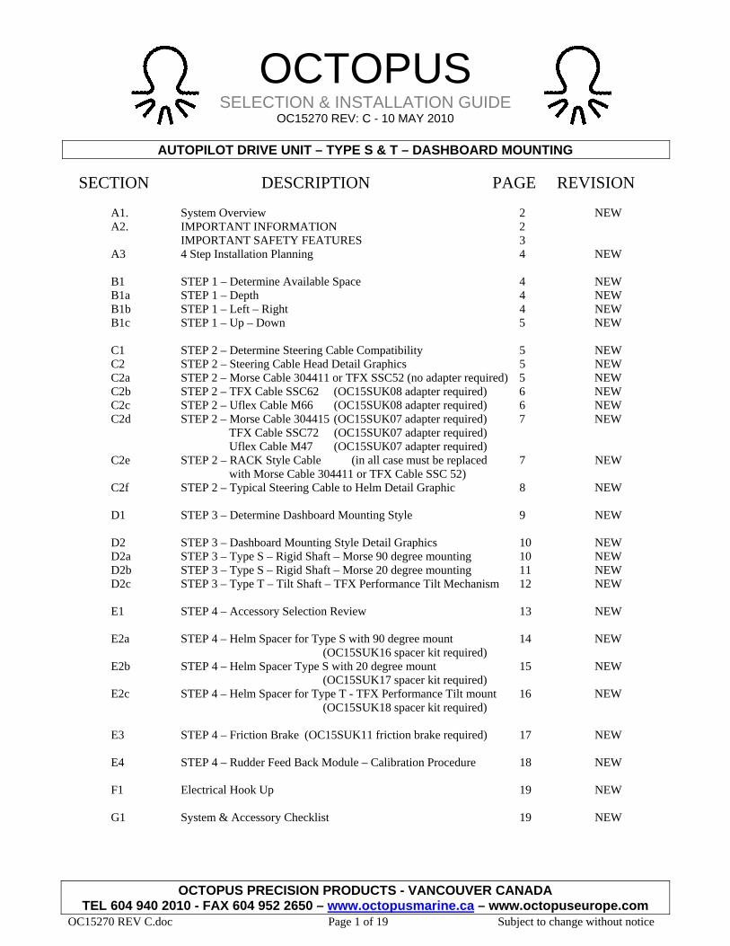
OCTOPUS SELECTION & INSTALLATION GUIDE OC15270 REV: C - 10 MAY 2010 AUTOPILOT DRIVE UNIT – TYPE S & T – DASHBOARD MOUNTING OCTOPUS PRECISION PRODUCTS - VANCOUVER CANADA TEL 604 940 2010 - FAX 604 952 2650 – www.octopusmarine.ca – www.octopuseurope.com OC15270 REV C.doc Page 1 of 19 Subject to change without notice SECTION DESCRIPTION PAGE REVISION A1. System Overview 2 NEW A2. IMPORTANT INFORMATION 2 IMPORTANT SAFETY FEATURES 3 A3 4 Step Installation Planning 4 NEW B1 STEP 1 – Determine Available Space 4 NEW B1a STEP 1 – Depth 4 NEW B1b STEP 1 – Left – Right 4 NEW B1c STEP 1 – Up – Down 5 NEW C1 STEP 2 – Determine Steering Cable Compatibility 5 NEW C2 STEP 2 – Steering Cable Head Detail Graphics 5 NEW C2a STEP 2 – Morse Cable 304411 or TFX SSC52 (no adapter required) 5 NEW C2b STEP 2 – TFX Cable SSC62 (OC15SUK08 adapter required) 6 NEW C2c STEP 2 – Uflex Cable M66 (OC15SUK08 adapter required) 6 NEW C2d STEP 2 – Morse Cable 304415 (OC15SUK07 adapter required) 7 NEW TFX Cable SSC72 (OC15SUK07 adapter required) Uflex Cable M47 (OC15SUK07 adapter required) C2e STEP 2 – RACK Style Cable (in all case must be replaced 7 NEW with Morse Cable 304411 or TFX Cable SSC 52) C2f STEP 2 – Typical Steering Cable to Helm Detail Graphic 8 NEW D1 STEP 3 – Determine Dashboard Mounting Style 9 NEW D2 STEP 3 – Dashboard Mounting Style Detail Graphics 10 NEW D2a STEP 3 – Type S – Rigid Shaft – Morse 90 degree mounting 10 NEW D2b STEP 3 – Type S – Rigid Shaft – Morse 20 degree mounting 11 NEW D2c STEP 3 – Type T – Tilt Shaft – TFX Performance Tilt Mechanism 12 NEW E1 STEP 4 – Accessory Selection Review 13 NEW E2a STEP 4 – Helm Spacer for Type S with 90 degree mount 14 NEW (OC15SUK16 spacer kit required) E2b STEP 4 – Helm Spacer Type S with 20 degree mount 15 NEW (OC15SUK17 spacer kit required) E2c STEP 4 – Helm Spacer for Type T - TFX Performance Tilt mount 16 NEW (OC15SUK18 spacer kit required) E3 STEP 4 – Friction Brake (OC15SUK11 friction brake required) 17 NEW E4 STEP 4 – Rudder Feed Back Module – Calibration Procedure 18 NEW F1 Electrical Hook Up 19 NEW G1 System & Accessory Checklist 19 NEW
Transcript
OCTOPUS SELECTION & INSTALLATION GUIDE
OC15270 REV: C - 10 MAY 2010
AUTOPILOT DRIVE UNIT – TYPE S & T – DASHBOARD MOUNTING
OCTOPUS PRECISION PRODUCTS - VANCOUVER CANADA TEL 604 940 2010 - FAX 604 952 2650 – www.octopusmarine.ca – www.octopuseurope.com
OC15270 REV C.doc Page 1 of 19 Subject to change without notice
SECTION DESCRIPTION PAGE REVISION
A1. System Overview 2 NEW A2. IMPORTANT INFORMATION 2 IMPORTANT SAFETY FEATURES 3 A3 4 Step Installation Planning 4 NEW B1 STEP 1 – Determine Available Space 4 NEW B1a STEP 1 – Depth 4 NEW B1b STEP 1 – Left – Right 4 NEW B1c STEP 1 – Up – Down 5 NEW C1 STEP 2 – Determine Steering Cable Compatibility 5 NEW C2 STEP 2 – Steering Cable Head Detail Graphics 5 NEW C2a STEP 2 – Morse Cable 304411 or TFX SSC52 (no adapter required) 5 NEW C2b STEP 2 – TFX Cable SSC62 (OC15SUK08 adapter required) 6 NEW C2c STEP 2 – Uflex Cable M66 (OC15SUK08 adapter required) 6 NEW C2d STEP 2 – Morse Cable 304415 (OC15SUK07 adapter required) 7 NEW TFX Cable SSC72 (OC15SUK07 adapter required) Uflex Cable M47 (OC15SUK07 adapter required) C2e STEP 2 – RACK Style Cable (in all case must be replaced 7 NEW with Morse Cable 304411 or TFX Cable SSC 52) C2f STEP 2 – Typical Steering Cable to Helm Detail Graphic 8 NEW D1 STEP 3 – Determine Dashboard Mounting Style 9 NEW D2 STEP 3 – Dashboard Mounting Style Detail Graphics 10 NEW D2a STEP 3 – Type S – Rigid Shaft – Morse 90 degree mounting 10 NEW D2b STEP 3 – Type S – Rigid Shaft – Morse 20 degree mounting 11 NEW D2c STEP 3 – Type T – Tilt Shaft – TFX Performance Tilt Mechanism 12 NEW E1 STEP 4 – Accessory Selection Review 13 NEW E2a STEP 4 – Helm Spacer for Type S with 90 degree mount 14 NEW (OC15SUK16 spacer kit required) E2b STEP 4 – Helm Spacer Type S with 20 degree mount 15 NEW (OC15SUK17 spacer kit required) E2c STEP 4 – Helm Spacer for Type T - TFX Performance Tilt mount 16 NEW (OC15SUK18 spacer kit required) E3 STEP 4 – Friction Brake (OC15SUK11 friction brake required) 17 NEW E4 STEP 4 – Rudder Feed Back Module – Calibration Procedure 18 NEW F1 Electrical Hook Up 19 NEW G1 System & Accessory Checklist 19 NEW
SELECTION & INSTALLATION GUIDE (continued) AUTOPILOT DRIVE UNIT – TYPE S & T – DASHBOARD MOUNTING
OCTOPUS PRECISION PRODUCTS - VANCOUVER CANADA TEL 604 940 2010 - FAX 604 952 2650– www.octopusmarine.ca – www.octopuseurope.com
OC15270 REV C.doc Page 2 of 19 Subject to change without notice
A1. SYSTEM OVERVIEW:
1. The Octopus rotary mechanical autopilot drive (model MDR-40) is an automatic pilot drive system which makes it easy and economical to install an automatic pilot on smaller powerboats steered with mechanical push pull cable steering systems and small sailboats with access to a quadrant or tiller. The unit is powerful and fast - capable of delivering over 300lbs of cable thrust, with a normal H.O. to H.O. time of 15 seconds.
2. The drive unit either replaces or is used in conjunction with common brands of mechanical rotary and rack &
pinion steering helm units, it incorporates a drive motor, a solenoid clutch and offers rudder feed back (RFB) capability. The MDR40 drive is based on the MORSE 290 rotary helm unit and accepts MORSE 304415 and Teleflex SSC52 rotary cables without modification. If the vessel is fitted with a TELLEFLEX ‘Safe T’ or ‘Big T’ or UFLEX ‘T71’, T73NR’, ‘T81’ system, a simple cable end adapter must be fitted to the cable before installing the drive. If the vessel is fitted with a rack and pinion type steering system (or other brands of rotary system), the MDR40 drive can be used, but the steering cable must also be replaced with a MORSE 304415 or Teleflex SSC52.
A2. IMPORTANT INFORMATION:
The MDR40 drive will fit a large number of vessels, which were just difficult or economically not practical to fit automatic pilots to before. The product does have some limitations, which must be observed, please note the following:
1. The MDR40 drive unit is designed around the MORSE 290 Rotary Drive Helm manufactured by Morse Controls
of Hudson Ohio, USA. To meet A.B.Y.C. regulations, this type of steering is recommended for use on vessels with a maximum speed of 40 m.p.h. The MDR40 should not be fitted to vessels, which exceed this speed.
2. The MDR40 drive unit should not be fitted to boats where the maximum horsepower of the engines exceeds the
maximum horsepower rating for the vessel as stated on the vessel manufacturers tag. 3. If the existing steering system on the vessel is a NFB (no feed back) type. The MDR40 drive, which is NOT a
NFB helm, can be fitted, but it is STRONGLY advised that the helmsman be formally familiarized with the operational characteristics of the new helm.
4. The MDR40 drive is designed to produce a maximum cable push/pull of 300lbs, which requires a peak power of
60 watts. This makes the unit very capable of handling the vast majority of cable steered vessels. However some vessels fitted with push pull cable steering systems have very stiff steering or steering which is heavily loaded in one direction due to hull design and engine considerations. Generally speaking, the MDR40 will steer vessels that do not require more than a 15-lb force on the rim of a 14-inch diameter steering wheel to hold a course, this equals 105 in/pounds of torque. If the steering wheel input torque exceeds this figure, the MDR40 is not a satisfactory drive system and we would suggest that the vessel be fitted with a hydraulic linear actuator drive system such as our OCTOPUS 1212LAM12.
SELECTION & INSTALLATION GUIDE (continued) AUTOPILOT DRIVE UNIT – TYPE S & T – DASHBOARD MOUNTING
OCTOPUS PRECISION PRODUCTS - VANCOUVER CANADA TEL 604 940 2010 - FAX 604 952 2650– www.octopusmarine.ca – www.octopuseurope.com
OC15270 REV C.doc Page 3 of 19 Subject to change without notice
5. IMPORTANT SAFETY FEATURES
Ensure that the Helmsperson is made aware of the two following safety features when using the Autopilot.
A: MANUAL RELEASE
A ‘manual release’ feature is included in the drive in case the Autopilot is switched to manual mode by mistake creating a dangerous manoeuvre or violent movement of the steering wheel on a Power Boat due to propeller action or trim forces. The drive unit while under consistent load from the boats steering system in one direction or no movement, will maintain the clutched engaged when the Autopilot is switched to manual mode. This feature minimizes uncontrolled boat swing, violent steering wheel movement and potentially dangerous manoeuvres. Manual Release Procedure. The wheel or tiller is required to be moved slightly to disengage the drive. A small joggle action (turning the wheel from side to side) will release the clutch and allow return to manual control. IMPORTANT The helmsperson should always be ready to take manual control of the boat when the Autopilot is returned to manual mode.
B: MANUAL OVERRIDE
In the event of UNCONTROLLED automatic steering or other EMERGENCY situations, automatic return to MANUAL steering is provided through the operation of a thrust limiter. It is STRONGLY advised that the helmsperson be formally familiarized with this MANUAL OVERIDE procedure. Manual Override Procedure. The helmsperson can overcome the steering action of the drive unit by exerting force on the steering wheel in the opposite direction to the drive. With this action the drive unit thrust limit will ‘slip’ allowing the helmsperson to take control. DOCKSIDE TESTING Due to the ‘Manual Release’ safety feature, when the yacht is not in motion it might be required to joggle the wheel/Tiller (move from side to side) to engage or disengage the drive. SEA TRIAL Before the Autopilot is tested at sea the helmsperson should be made aware of the two safety features and the procedures required.
SELECTION & INSTALLATION GUIDE (continued) AUTOPILOT DRIVE UNIT – TYPE S & T – DASHBOARD MOUNTING
A3 4 – STEP INSTALLATION PLANNING:
When planning an installation, it is recommended that you follow 4 steps :
STEP 1: Ensure that there is adequate space available to accommodate the drive. STEP 2: Determine the compatibility of the existing steering cable – cable adapter selection.
B1 STEP 1 – Determine Available Space behind dashboard
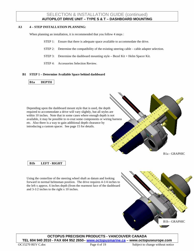
B1a DEPTH
Depending upon the dashboard mount style that is used, the depth required to accommodate a drive will vary slightly, but all styles are within 10 inches. Note that in some cases where enough depth is not available, it may be possible to re-rout some components or wiring harness etc. Also there is a way to gain additional depth clearance by introducing a custom spacer. See page 15 for details.
B1a - GRAPHIC
B1b LEFT - RIGHT
Using the centerline of the steering wheel shaft as datum and looking forward in normal helmsman position. The drive requires 4-1/4 inches to the left x approx. 6 inches depth (from the rearmost face of the dashboard and 3-1/2 inches to the right x 10 inches.
B1b - GRAPHIC
OCTOPUS PRECISION PRODUCTS - VANCOUVER CANADA TEL 604 940 2010 - FAX 604 952 2650– www.octopusmarine.ca – www.octopuseurope.com
OC15270 REV C.doc Page 4 of 19 Subject to change without notice
SELECTION & INSTALLATION GUIDE (continued) AUTOPILOT DRIVE UNIT – TYPE S & T – DASHBOARD MOUNTING
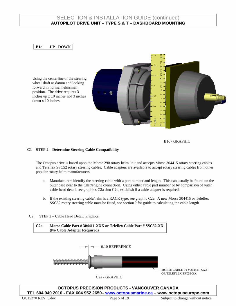
B1c UP - DOWN
Using the centerline of the steering wheel shaft as datum and looking forward in normal helmsman position. The drive requires 3 inches up x 10 inches and 3 inches down x 10 inches.
The Octopus drive is based upon the Morse 290 rotary helm unit and accepts Morse 304415 rotary steering cables and Teleflex SSC52 rotary steering cables. Cable adapters are available to accept rotary steering cables from other popular rotary helm manufacturers.
a. Manufacturers identify the steering cable with a part number and length. This can usually be found on the
outer case near to the tiller/engine connection. Using either cable part number or by comparison of outer cable head detail, see graphics C2a thru C2d, establish if a cable adapter is required.
b. If the existing steering cable/helm is a RACK type, see graphic C2e. A new Morse 304415 or Teleflex
SSC52 rotary steering cable must be fitted, see section ? for guide to calculating the cable length.
C2. STEP 2 – Cable Head Detail Graphics
C2a. Morse Cable Part # 304411-XXX or Teleflex Cable Part # SSC52-XX (No Cable Adapter Required)
C2a - GRAPHIC
0.10 REFERENCE
MORSE CABLE PT # 304411-XXX OR TELEFLEX SSC52-XX
OCTOPUS PRECISION PRODUCTS - VANCOUVER CANADA TEL 604 940 2010 - FAX 604 952 2650– www.octopusmarine.ca – www.octopuseurope.com
OC15270 REV C.doc Page 5 of 19 Subject to change without notice
SELECTION & INSTALLATION GUIDE (continued) AUTOPILOT DRIVE UNIT – TYPE S & T – DASHBOARD MOUNTING
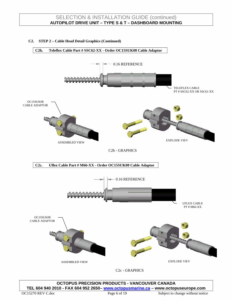
C2. STEP 2 – Cable Head Detail Graphics (Continued)
C2b. Teleflex Cable Part # SSC62-XX - Order OC15SUK08 Cable Adaptor
C2b - GRAPHICS
EXPLODE VIEVASSEMBLED VIEW
OC15SUK08 CABLE ADAPTOR
0.16 REFERENCE
TELEFLEX CABLE PT # SSC62-XX OR SSC61-XX
C2c. Uflex Cable Part # M66-XX - Order OC15SUK08 Cable Adaptor
0.16 REFERENCE
UFLEX CABLE PT # M66-XX
OCTOPUS PRECISION PRODUCTS - VANCOUVER CANADA TEL 604 940 2010 - FAX 604 952 2650– www.octopusmarine.ca – www.octopuseurope.com
OC15270 REV C.doc Page 6 of 19 Subject to change without notice
C2c - GRAPHICS
EXPLODE VIEV
OC15SUK08 CABLE ADAPTOR
ASSEMBLED VIEW
SELECTION & INSTALLATION GUIDE (continued) AUTOPILOT DRIVE UNIT – TYPE S & T – DASHBOARD MOUNTING
C2. STEP 2 – Cable Head Detail Graphics (Continued)
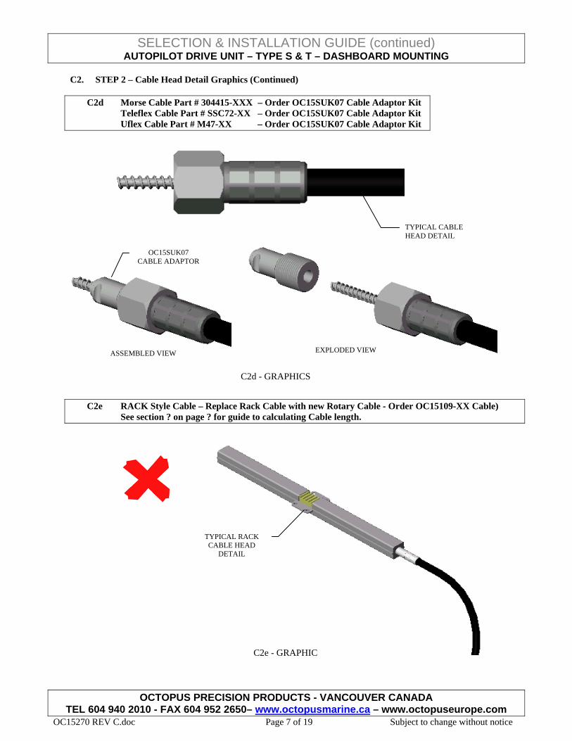
C2d Morse Cable Part # 304415-XXX – Order OC15SUK07 Cable Adaptor Kit Teleflex Cable Part # SSC72-XX – Order OC15SUK07 Cable Adaptor Kit Uflex Cable Part # M47-XX – Order OC15SUK07 Cable Adaptor Kit
OCTOPUS PRECISION PRODUCTS - VANCOUVER CANADA TEL 604 940 2010 - FAX 604 952 2650– www.octopusmarine.ca – www.octopuseurope.com
OC15270 REV C.doc Page 7 of 19 Subject to change without notice
TYPICAL CABLE HEAD DETAIL
C2e RACK Style Cable – Replace Rack Cable with new Rotary Cable - Order OC15109-XX Cable) See section ? on page ? for guide to calculating Cable length.
EXPLODED VIEW
C2d - GRAPHICS
OC15SUK07 CABLE ADAPTOR
ASSEMBLED VIEW
C2e - GRAPHIC
TYPICAL RACK CABLE HEAD
DETAIL
SELECTION & INSTALLATION GUIDE (continued) AUTOPILOT DRIVE UNIT – TYPE S & T – DASHBOARD MOUNTING
C2 STEP 2 – Cable Head Detail Graphics (Continued)
C2f STEP 2 – Typical Cable Head to Helm Installation Graphic
OCTOPUS PRECISION PRODUCTS - VANCOUVER CANADA TEL 604 940 2010 - FAX 604 952 2650– www.octopusmarine.ca – www.octopuseurope.com
OC15270 REV C.doc Page 8 of 19 Subject to change without notice
GRAPHIC C2f EXPLODED VIEW
BASIC HARDWARE
SPENT CABLE TUBE
MORSE CABLE PT # 30441-XX OR TELEFLEX CABLE PT # SSC52-XX OR OCTOPUS PT # OC150109-XX
BASIC HARDWARE
MORSE CABLE PT # 304411-XXX OR TELEFLEX CABLE PT # SSC52-XX OR OCTOPUS PT # OC1500109-XX
GRAPHIC C2f ASSEMBLED VIEW
TFX SSC62 OR SSC61 OR UFLEX M66 CABLE WITH CABLE ADAPTER OCTOPUS PT # OC15SUK08
SPENT CABLE TUBE
TFX SSC72 OR UFLEX M47 OR MORSE 304415 CABLE WITH CABLE ADAPTER OCTOPUS PT # OC15SUK07
SELECTION & INSTALLATION GUIDE (continued) AUTOPILOT DRIVE UNIT – TYPE S & T – DASHBOARD MOUNTING
OCTOPUS PRECISION PRODUCTS - VANCOUVER CANADA TEL 604 940 2010 - FAX 604 952 2650– www.octopusmarine.ca – www.octopuseurope.com
OC15270 REV C.doc Page 9 of 19 Subject to change without notice
D1 STEP 3 – Determine the Dashboard Mounting Style
In order to accommodate the full range of dashboard mounting orientations, bezels and rigid/tilt steering wheel shaft options. The Octopus drive can be mounted to the dashboard panel in a variety of ways using different mounting brackets and if required, spacers and bezel kits. There are 2 main dashboard mounting types.
TYPE S – STRAIGHT SHAFT: This type can be mounted in 2 ways, either at 90 degrees to the dashboard or at 20 degrees to the dashboard. Spacer Kits are also available to reduce the space required behind the dashboard. See graphics D2a & D2b for basic Bezel Kits and E2a & E2b for Bezel Kits + Spacer Kits. TYPE T – TILT SHAFT: This type mates the drive with the tilt steering mechanism that was supplied with the original steering system. Currently the Teleflex Performance Tilt mechanism is supported by a factory configured drive unit. Spacer Kits are also available to reduce the space required behind the dashboard. See graphics D2c for basic Tilt Mechanism and E2c for Tilt Mechanism + Spacer Kits. NOTE: Consult factory for information on available retro-fit components for mating to older Tilt Mechanisms manufactured by Morse, Teleflex and Uflex.
SELECTION & INSTALLATION GUIDE (continued) AUTOPILOT DRIVE UNIT – TYPE S & T – DASHBOARD MOUNTING
D2a TYPE S – STRAIGHT SHAFT: Morse 90 Degree Mounting
REQUIRED PARTS:
a. Octopus Part Number AFMDMSRW (straight shaft drive unit) b. Octopus Part Number OC15SUK10 (90 degree bezel kit) c. Octopus Part Number OC15SUK06A thru E (rudder feed back kit)
See section E3 on page 19 for additional selection information
OCTOPUS PRECISION PRODUCTS - VANCOUVER CANADA TEL 604 940 2010 - FAX 604 952 2650– www.octopusmarine.ca – www.octopuseurope.com
OC15270 REV C.doc Page 10 of 19 Subject to change without notice
ASSEMBLED VIEW (bezel omitted)
COMPLETE INSTALLATION
DASHBOARD
DASHBOARD PREPARATION
90 DEGREE BEZEL KIT MODEL OC15SUK10
DRIVE UNIT MODEL AFMDMSRW
DASHBOARD (cut away)
EXPLODED VIEW
SELECTION & INSTALLATION GUIDE (continued) AUTOPILOT DRIVE UNIT – TYPE S & T – DASHBOARD MOUNTING
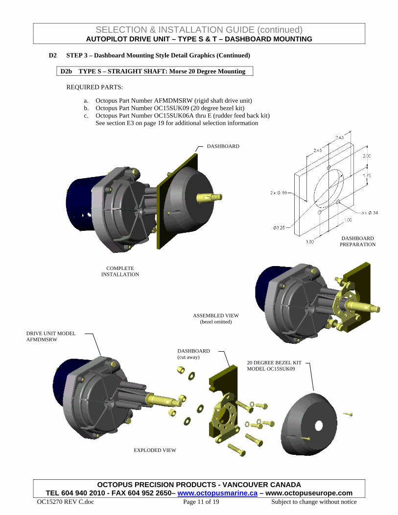
D2b TYPE S – STRAIGHT SHAFT: Morse 20 Degree Mounting
REQUIRED PARTS:
a. Octopus Part Number AFMDMSRW (rigid shaft drive unit) b. Octopus Part Number OC15SUK09 (20 degree bezel kit) c. Octopus Part Number OC15SUK06A thru E (rudder feed back kit)
See section E3 on page 19 for additional selection information
ASSEMBLED VIEW (bezel omitted)
COMPLETE INSTALLATION
DASHBOARD
DRIVE UNIT MODEL AFMDMSRW
DASHBOARD (cut away)
20 DEGREE BEZEL KIT MODEL OC15SUK09
EXPLODED VIEW
DASHBOARD PREPARATION
OCTOPUS PRECISION PRODUCTS - VANCOUVER CANADA TEL 604 940 2010 - FAX 604 952 2650– www.octopusmarine.ca – www.octopuseurope.com
OC15270 REV C.doc Page 11 of 19 Subject to change without notice
SELECTION & INSTALLATION GUIDE (continued) AUTOPILOT DRIVE UNIT – TYPE S & T – DASHBOARD MOUNTING
D2c. TYPE T – TILT SHAFT: TFX Performance Tilt Mechanism
REQUIRED PARTS:
a. Octopus Part Number AFMDTPRW (TFX Performance tilt drive unit) b. Octopus Part Number OC15SUK06A thru E (rudder feed back kit)
See section E3 on page 19 for additional selection information c. Teleflex Performance Tilt Mechanism (supplied by end user)
DASHBOARD PREPARATION
ASSEMBLED VIEW (tilt mechanism omitted)
EXPLODED VIEW
DASHBOARD
DRIVE UNIT MODEL AFMDTPRW
TILT MECHANISM (supplied by others)
COMPLETE INSTALLATION
DASHBOARD
OCTOPUS PRECISION PRODUCTS - VANCOUVER CANADA TEL 604 940 2010 - FAX 604 952 2650– www.octopusmarine.ca – www.octopuseurope.com
OC15270 REV C.doc Page 12 of 19 Subject to change without notice
SELECTION & INSTALLATION GUIDE (continued) AUTOPILOT DRIVE UNIT – TYPE S & T – DASHBOARD MOUNTING
OCTOPUS PRECISION PRODUCTS - VANCOUVER CANADA TEL 604 940 2010 - FAX 604 952 2650– www.octopusmarine.ca – www.octopuseurope.com
OC15270 REV C.doc Page 13 of 19 Subject to change without notice
E1. STEP 4 – Accessory Selection Review
There are 6 types of accessory to be considered.
RUDDER FEED BACK MECHANISM: All autopilot installations require a rudder angle feed back device. The Octopus mechanism is based upon a rotary potentiometer, attaches directly to the drive unit with 2 screws and the calibration procedure is simple. Alternate devices attach directly to the tiller arm using a linkage mechanism; they require hard wiring and adequate protection from the elements and in many cases from accidental damage due to poor stowage of equipment or simply being stepped on. See graphic E4 on page 17 for further details. STEERING CABLE ADAPTERS: When replacing the originally installed rotary helm unit, it is usually possible to re-use the original steering cable. The most popular types of rotary steering cable can be adapted to mate with the Octopus drive unit. See section C on pages 4 thru 7 for further details. Note that when replacing a “RACK” type helm a new rotary steering cable must ALWAYS be fitted.
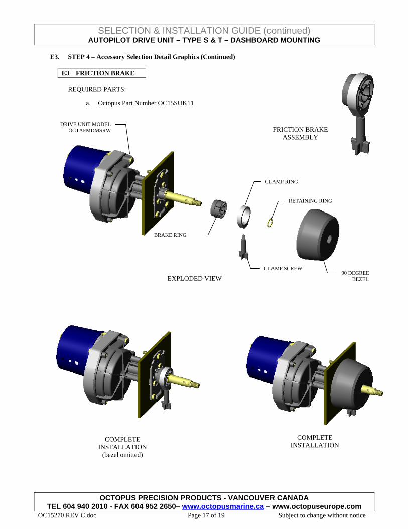
HELM BEZEL KIT: Helm bezel kits are used to mount the straight shaft helm to the dashboard and provide an aesthetic finish. They are available in black only at either 90 degree or 20 degree. See section D on page 8 thru 10 for further details. TILT MECHANISM: The available factory configured tilt shaft drive unit is designed to mate with the Teleflex Performance Tilt Mechanism. Retro-fit components are available to enable drive units to mate with older types of tilt mechanism from Morse, Teleflex and Uflex. Consult factory for more details. HELM SPACER KIT: These spacer kits can be used to shift the helm rearwards in order to reduce the amount of space required behind the dashboard. The kits consist of multiple stackable spacers and connection hardware. The individual spacers are manufactured from aluminum and are protected from the environment with a black anodized finish. Consult factory for other finishing options. See graphics E2a thru E2c on page 13 thru 15 for further details. FRICTION BRAKE: This device is only available for the TYPE S – STRAIGHT SHAFT installation. It attaches to the neck of the helm and steering shaft and applies an adjustable friction force resisting the rotation of the steering shaft. It has the effect of dampening out helm backlash and resisting steering bias loads that can be transmitted from the forces created by propeller wash, especially on outboard engine installations. See graphic E3 on page 16 for further details.
SELECTION & INSTALLATION GUIDE (continued) AUTOPILOT DRIVE UNIT – TYPE S & T – DASHBOARD MOUNTING
E2. STEP 4 – Accessory Selection Detail Graphics
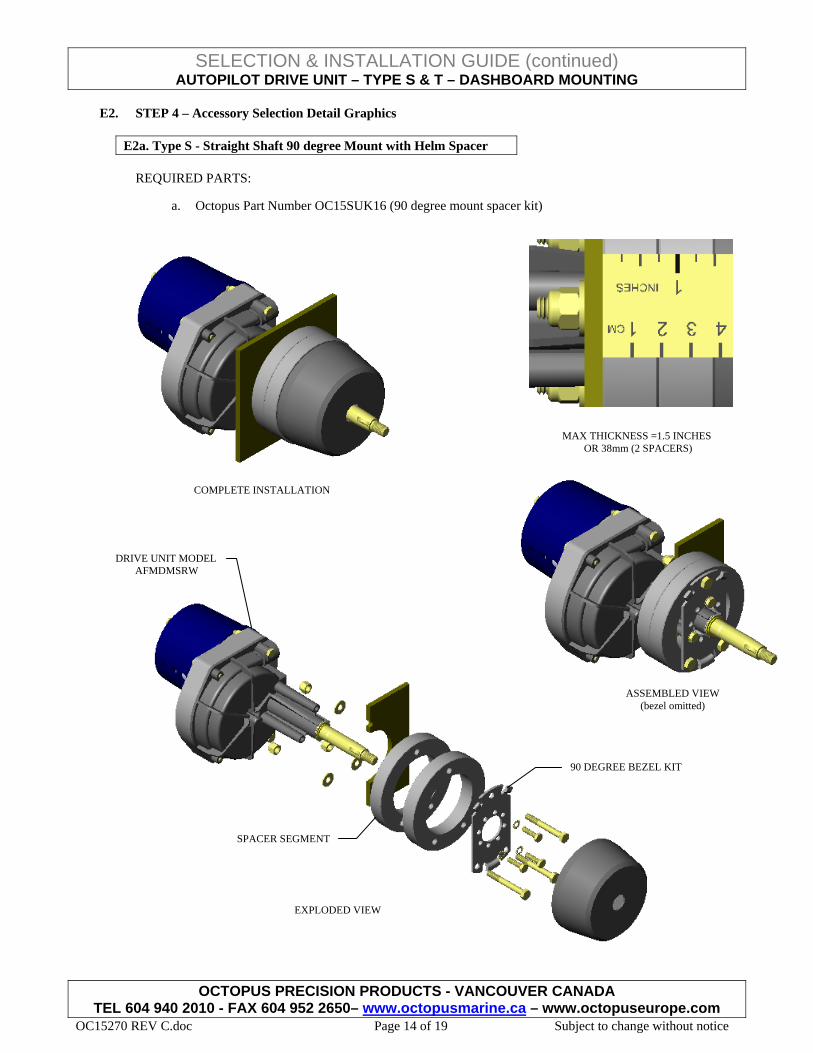
E2a. Type S - Straight Shaft 90 degree Mount with Helm Spacer
REQUIRED PARTS:
a. Octopus Part Number OC15SUK16 (90 degree mount spacer kit)
COMPLETE INSTALLATION
MAX THICKNESS =1.5 INCHES OR 38mm (2 SPACERS)
90 DEGREE BEZEL KIT
EXPLODED VIEW
SPACER SEGMENT
DRIVE UNIT MODEL AFMDMSRW
ASSEMBLED VIEW (bezel omitted)
OCTOPUS PRECISION PRODUCTS - VANCOUVER CANADA TEL 604 940 2010 - FAX 604 952 2650– www.octopusmarine.ca – www.octopuseurope.com
OC15270 REV C.doc Page 14 of 19 Subject to change without notice
SELECTION & INSTALLATION GUIDE (continued) AUTOPILOT DRIVE UNIT – TYPE S & T – DASHBOARD MOUNTING
OCTOPUS PRECISION PRODUCTS - VANCOUVER CANADA TEL 604 940 2010 - FAX 604 952 2650– www.octopusmarine.ca – www.octopuseurope.com
OC15270 REV C.doc Page 18 of 19 Subject to change without notice
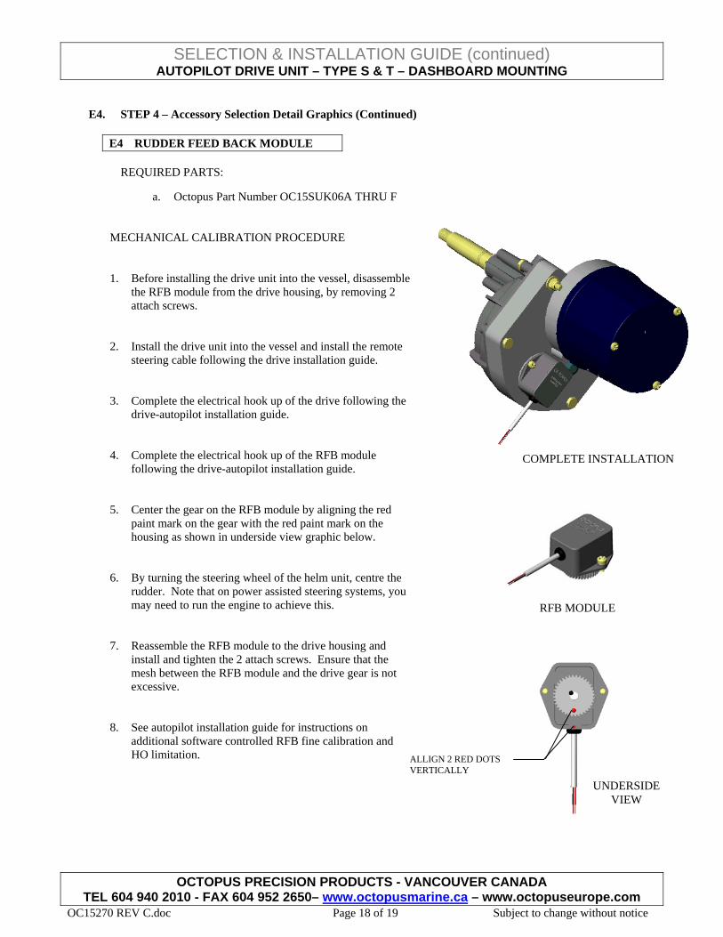
MECHANICAL CALIBRATION PROCEDURE
1. Before installing the drive unit into the vessel, disassemble
the RFB module from the drive housing, by removing 2 attach screws.
2. Install the drive unit into the vessel and install the remote
steering cable following the drive installation guide.
3. Complete the electrical hook up of the drive following the
drive-autopilot installation guide. 4. Complete the electrical hook up of the RFB module
following the drive-autopilot installation guide.
5. Center the gear on the RFB module by aligning the red paint mark on the gear with the red paint mark on the housing as shown in underside view graphic below.
6. By turning the steering wheel of the helm unit, centre the rudder. Note that on power assisted steering systems, you may need to run the engine to achieve this.
COMPLETE INSTALLATION
RFB MODULE
UNDERSIDEVIEW
ALLIGN 2 RED DOTS VERTICALLY
7. Reassemble the RFB module to the drive housing and install and tighten the 2 attach screws. Ensure that the mesh between the RFB module and the drive gear is not excessive.
8. See autopilot installation guide for instructions on additional software controlled RFB fine calibration and HO limitation.
SELECTION & INSTALLATION GUIDE (continued) AUTOPILOT DRIVE UNIT – TYPE S & T – DASHBOARD MOUNTING
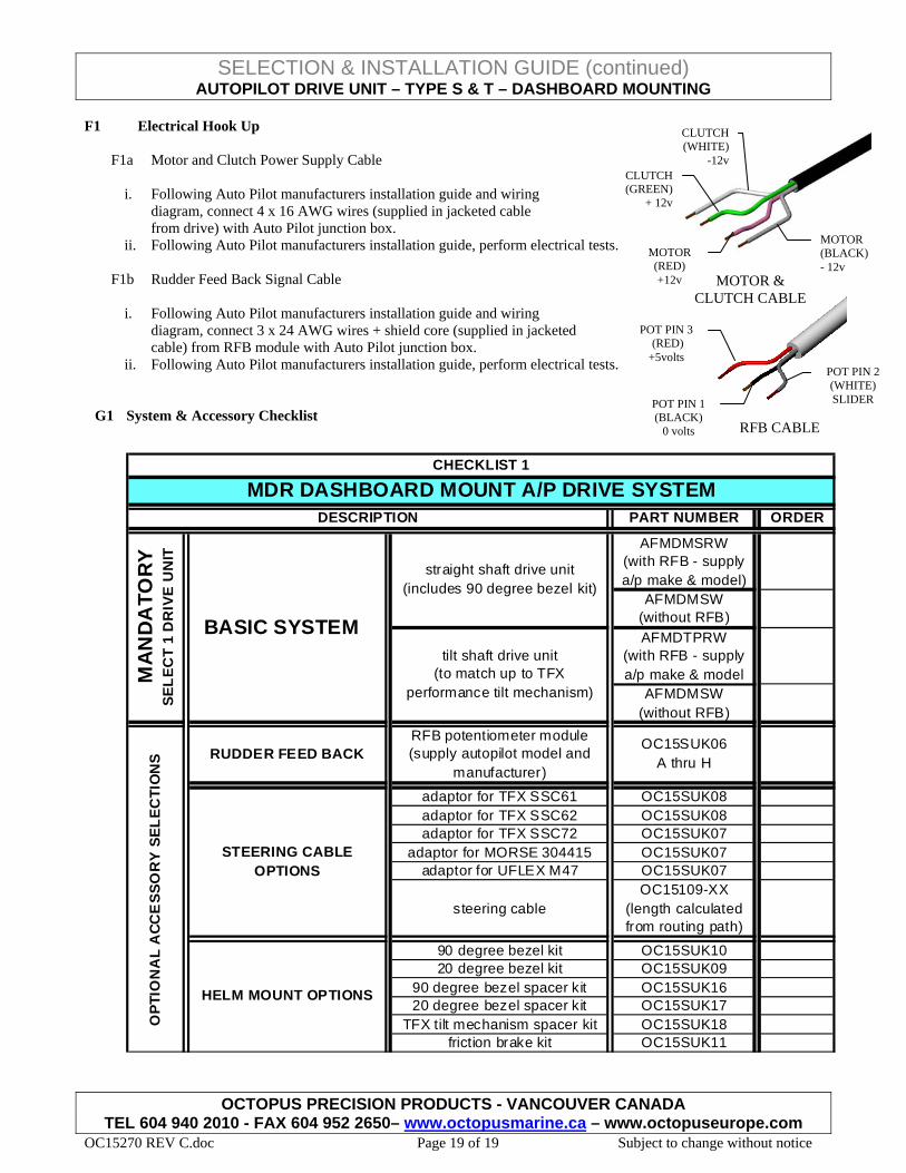
F1 Electrical Hook Up
OCTOPUS PRECISION PRODUCTS - VANCOUVER CANADA TEL 604 940 2010 - FAX 604 952 2650– www.octopusmarine.ca – www.octopuseurope.com
OC15270 REV C.doc Page 19 of 19 Subject to change without notice
F1a Motor and Clutch Power Supply Cable
i. Following Auto Pilot manufacturers installation guide and wiring diagram, connect 4 x 16 AWG wires (supplied in jacketed cable from drive) with Auto Pilot junction box.
ii. Following Auto Pilot manufacturers installation guide, perform electrical tests.
F1b Rudder Feed Back Signal Cable
i. Following Auto Pilot manufacturers installation guide and wiring diagram, connect 3 x 24 AWG wires + shield core (supplied in jacketed cable) from RFB module with Auto Pilot junction box.
ii. Following Auto Pilot manufacturers installation guide, perform electrical tests.
POT PIN 1 (BLACK)
0 volts
POT PIN 3 (RED) +5volts
POT PIN 2 (WHITE) SLIDER
RFB CABLE
MOTOR (RED) +12v
MOTOR (BLACK) - 12v
CLUTCH (GREEN)
+ 12v
CLUTCH (WHITE)
-12v
MOTOR & CLUTCH CABLE
G1 System & Accessory Checklist
PART NUMBER ORDER
AFMDMSRW (with RFB - supply a/p make & model)
AFMDMSW (without RFB)AFMDTPRW
(with RFB - supply a/p make & model
AFMDMSW (without RFB)
adaptor for TFX SSC61 OC15SUK08adaptor for TFX SSC62 OC15SUK08adaptor for TFX SSC72 OC15SUK07
adaptor for MORSE 304415 OC15SUK07adaptor for UFLEX M47 OC15SUK07