42
NTIA Handbook HB-11-441d Batch Video Quality Metric (BVQM) User’s Manual Margaret H. Pinson Stephen Wolf

NTIA Handbook HB-11-441d
Batch Video Quality Metric (BVQM) User’s Manual
Margaret H. Pinson Stephen Wolf


NTIA Handbook HB-11-441d
Batch Video Quality Metric (BVQM) User’s Manual
Margaret H. Pinson Stephen Wolf
U.S. DEPARTMENT OF COMMERCE
September 2011

iii
DISCLAIMER
Certain commercial equipment, software packages, and materials are identified in this report to
specify adequately the technical aspects of the reported results. In no case does such
identification imply recommendation or endorsement by the National Telecommunications and
Information Administration (NTIA) or the Institute for Telecommunication Sciences (ITS), nor
does it imply that the equipment, software, or materials identified are necessarily the best
available for the particular application or use.
This document describes software developed by NTIA. NTIA does not make any warranty of
any kind, express, implied or statutory, including, without limitation, the implied warranty
of merchantability, fitness for a particular purpose, non-infringement and data accuracy.
This software is provided "AS IS." NTIA does not warrant or make any representations
regarding the use of the software or the results thereof, including but not limited to the
correctness, accuracy, reliability or usefulness of the software or the results. You can use, copy,
modify, and redistribute the NTIA-developed software upon your acceptance of these terms and
conditions, and upon your express agreement to provide appropriate acknowledgments of
NTIA's ownership of and development of the software by keeping this exact text present in any
copied or derivative works.
The user of this software (“Collaborator”) agrees to hold the U.S. Government harmless and
indemnifies the U.S. Government for all liabilities, demands, damages, expenses, and losses
arising out of the use by the Collaborator, or any party acting on its behalf, of NTIA/ITS’
software, or out of any use, sale, or other disposition by the Collaborator, or others acting on its
behalf, of products made by the use of NTIA/ITS’ software.

iv
v
CONTENTS
Page
1. INTRODUCTION ................................................................................................................. 1
2. REQUIREMENTS ................................................................................................................ 3
3. INSTALLATION PROCEDURE .......................................................................................... 4
4. OPERATIONAL OVERVIEW ............................................................................................. 5
4.1 Video File Constraints ..................................................................................................5
4.2 File Naming Convention for Automated Processing......................................................6
4.3 Long Video Files ..........................................................................................................7
4.4 Starting BVQM ............................................................................................................7
4.5 Specifying the Results Directory and Clips Directory ...................................................7
4.6 Automatic Crash Recovery ...........................................................................................9
5. PROCESSING VIDEO CLIPS ............................................................................................ 10
5.1 Selecting Video Clips to Analyze ............................................................................... 10
5.2 Specifying Image Size ................................................................................................ 11
5.3 Specifying Video Clip Data ........................................................................................ 12
6. SPECIFYING CALIBRATION AND A VIDEO QUALITY MODEL ................................ 14
6.1 Calibration Selection .................................................................................................. 15
6.2 Additional Calibration Options ................................................................................... 17
6.3 Video Quality Model Selection ................................................................................... 17
7. MANUAL CALIBRATION SETTINGS ............................................................................. 20
7.1 HRC Calibration Information (Sheet 1) ...................................................................... 20
7.2 Scene Calibration Information (Sheet 2) ..................................................................... 21
7.3 Clip Calibration Information (Sheet 3) ........................................................................ 23
7.4 Error Troubleshooting ................................................................................................ 24
8. VIEWING RESULTS ......................................................................................................... 26
9. EXITING BVQM ................................................................................................................ 28
10. KNOWN ISSUES ............................................................................................................... 29
11. ACKNOWLEDGMENTS ................................................................................................... 30
12. REFERENCES.................................................................................................................... 31

vi
FIGURES
Page
Figure 1. Results directory selection window...............................................................................8
Figure 2. Video clip directory selection window. .........................................................................9
Figure 3. Main BVQM window. ................................................................................................ 10
Figure 4. Select image size window. .......................................................................................... 11
Figure 5. 15 seconds maximum window. ................................................................................... 12
Figure 6. Parse window. ............................................................................................................ 13
Figure 7. Calibration and model selection window. ................................................................... 14
Figure 8. LoadManualCalibration_sheet1.csv file (HRC information). ...................................... 20
Figure 9. LoadManualCalibration_sheet2.csv file (scene information). ...................................... 22
Figure 10. LoadManualCalibration_sheet3.csv file (clip information). ...................................... 23
Figure 11. Video Quality Measurement Results window. .......................................................... 27
BATCH VIDEO QUALITY METRIC (BVQM) USER’S MANUAL
Margaret H. Pinson, Stephen Wolf1
This handbook provides a user’s manual for the batch video quality metric
(BVQM) tool. BVQM runs under the Windows XP® or Windows 7
® operating
systems. BVQM performs objective automated quality assessments of processed
video clip batches (i.e., as output by a video system under test). BVQM reports
video calibration and quality metric results such as: temporal registration, spatial
registration, spatial scaling, valid region, gain/level offset, and objective video
quality estimates. BVQM operates on original and processed video files only, and
has no video capture capability.
BVQM compares the original video clip to the processed video clip and reports
quality estimates on a scale from zero to one. On this scale, zero means that no
impairment is visible and one means that the video clip has reached the maximum
impairment level (excursions beyond one are possible for extremely impaired
video sequences).
Key words: automatic measurements; batch video clip processing; digital video; metrics;
objective video quality performance; video calibration; video quality
1. INTRODUCTION
The Institute for Telecommunication Sciences (ITS) has developed a video quality metric
(BVQM) software tool that performs automated batch processing of multiple video clips to
objectively assess their video quality. Section 6 describes the video quality measurement options
BVQM implements, including how to:
Perform calibration of the sampled video files (i.e., spatial scaling, spatial registration,
valid region estimation, gain/level offset, and temporal registration)
Determine which video quality models to use for estimating the overall quality perception
This user’s guide does not specify the algorithms BVQM utilizes. If you need more information
about the algorithms that are used, see the references given in Section 6.
BVQM provides a graphical user interface (GUI) to select the video clips you want to batch
process. Processing consists of calibrating the processed video clips and calculating their
1 The authors are with the Institute for Telecommunication Sciences, National Telecommunications and Information
Administration, U.S. Department of Commerce, 325 Broadway, Boulder, CO 80305.

2
associated video quality metrics. You can manually set calibration values, or choose between
several automated calibration options. Multiple video quality model options are also available.
After processing, BVQM displays the results graphically and provides text file reports. All
results are available for viewing or export to spreadsheet software.
3
2. REQUIREMENTS
BVQM requires one computer with the following minimum criteria:
3 GHz Pentium Processor (Quad Core recommended)
Windows XP (for 32-bit), or Windows 7 (for 64-bit). Windows 7 64-bit is highly
recommended as XP 32-bit does not support usable RAM configurations larger than 2
GB.
4 GB RAM for standard definition, 16 GB RAM for high definition. The RAM
requirements are highly dependent on the clip duration, clip resolution, and the user
selected calibration and model options.
> 4 GB free disk space (depends on video clips being processed)
1600 × 1200 pixel resolution monitor
MATLAB® Component Runtime (MCR) library
For 8-second video scenes sampled in accordance with Rec. 601 [1], BVQM can require up to 4
GB of free memory depending upon calibration and model options selected. An “out of memory”
error will result if there is insufficient RAM.
Warning: Insufficient disk space or memory will prevent BVQM from running
successfully.

4
3. INSTALLATION PROCEDURE
If a prior version of BVQM was installed, you must first uninstall the old version of the
MATLAB Component Runtime Library before proceeding and install the version supplied with
the BVQM software. To uninstall the old MATLAB Component Runtime Library, from the
Windows Start menu, select Control Panel > Add/Remove Programs. From the list of
programs, select MATLAB Component Runtime, then click Remove.
Follow these steps to install BVQM:
1. Copy the files on the BVQM installation CD to a directory on your computer. This
directory will be denoted as C:\bvqm for the rest of the installation instructions given
below, but any directory may be chosen.
2. Double-click MCRInstaller.exe in C:\bvqm and follow the instructions to install the MCR
library on your computer.
3. After completing installation, check to make sure that the MCR library is installed
properly. From the Windows Start menu, select Control Panel, then double-click Add
or Remove Programs and see if the MATLAB Component Runtime library appears in
the list of installed programs. If not, repeat step 2.

5
4. OPERATIONAL OVERVIEW
You can process multiple video clips at once with BVQM in six steps:
1. Select a results directory. The BVQM software will start and display the browse window
for the Results directory. This directory stores temporary files and report files that contain
BVQM results. See Section 4.5.
2. Select a video clip directory. This directory contains all the video clip files that will be
examined by BVQM. See Section 4.5
3. Select the video files. Select the original and processed video files to be analyzed by
BVQM. BVQM might request additional information on the video clips (e.g., field
ordering) when video files are selected. See Section 5.
4. Select calibration type and model. Select the calibration option and video quality model
that you want BVQM to use. See Section 6.
5. [Optional] Enter manual calibration settings. You can enter additional manual calibration
information for each video sequence. See Section 7.
6. Wait for results. BVQM reports results to the results window and saves them to the
results directory. See Section 8.
Steps 3 to 6 are fully documented in Section 5 through Section 8, respectively.
4.1 Video File Constraints
BVQM can only operate on video files that are saved in certain formats. The first format
supported by BVQM is Audio Video Interleave (AVI). Only uncompressed AVI files are
supported. These uncompressed AVI files must contain either the UYVY, YUY2, YV12, V210,
or RGB24 format. BVQM will run slightly faster on AVI files containing one of the non-RGB24
formats. Compressed AVI files must be converted into uncompressed AVI files prior to use by
BVQM. Note, however, that the video distortions caused by the compression will influence the
results.
The second format, called “Big YUV” in this document, is a convenient binary file format for
storing Rec. 601 sampled video [1]. BVQM will run faster using Big YUV files rather than
uncompressed AVI files. In the Big YUV format all the frames are stored sequentially in one big
binary file. The sampling is 4:2:2 and image pixels are stored sequentially by video scan line as
bytes in the following order: Cb1 Y1 Cr1 Y2 Cb3 Y3 Cr3 Y4…, where Y is the luminance
component, Cb is the blue chrominance component, Cr is the red chrominance component, and
the subscript is the pixel number. The Y signal is quantized into 220 levels where black = 16 and
white = 235, while the Cb and Cr signals are quantized into 225 levels with zero signal
corresponding to 128. Occasional excursions beyond these levels may occur. For example, Y=15
may be produced by a real system, but in any case, Y, Cb, and Cr values are always between 0

6
and 255. The two chrominance components (Cb and Cr) are sub-sampled by two horizontally.
BVQM will run faster on Big-YUV files than on uncompressed AVI files.2
Converting video from other formats into the formats required for BVQM to operate is outside
the scope of this document. Video conversion issues can be quite complex. Care should be taken
to preserve field ordering (i.e., field one remains in field one, and field two remains in field two).
If video is acquired via frame grabbing, make sure there are no missing or dropped video frames,
as this will affect the video quality measurement. Unnecessary color space conversions (e.g.,
from RGB24 to UYVY and vice versa) should also be avoided.
4.2 File Naming Convention for Automated Processing
BVQM automatically determines how to process video files by examining the video file names.
Setup time is therefore greatly reduced when standard file names are used for all video files. The
standard filename convention for the BVQM software is “scene_hrc” followed by the suffix
“.avi” for AVI files or “.yuv” for Big-YUV files. The “scene” and “hrc” names are short strings
containing only letters and numbers. The user may specify an alternate standard naming
convention of the form “test_scene_hrc.avi” or “test_scene_hrc.yuv”. However, the current
version of BVQM can only analyze one video test (i.e., a batch of video clip files from one
experiment or test) at a time.
“Scene” identifies a single video sequence (e.g., segment of video). All versions of the same
scene should be given the same name.
“HRC” or “Hypothetical Reference Circuit” indicates a video system under test such as a coder
operating at a certain bit rate over a digital transmission channel and being decoded by a
decoder. Whenever any parameter is changed on the coder, transmission channel, or decoder,
this should be named as a different HRC. BVQM obtains increased accuracy by examining
multiple scenes that have been passed through the same HRC. Thus, HRC names must be used
carefully and accurately.
The HRC name “original” refers to the highest quality version of the “scene” that is available,
and this will be used as the reference sequence for the measurements for that scene. The original
is normally the input video sequence that was passed through the HRCs to create the processed
video sequences. Preferably, the original video should never have been compressed. Original
video sequences should appear to have either “Excellent” or “Good” quality when examined
visually. Poor quality original video sequences (e.g., with visible compression artifacts) may
reduce BVQM accuracy. The original video sequence must be available to BVQM.
If non-standard file names are used, you must enter the scene and HRC naming information
manually for each clip. The original must be identified with an HRC name of “original”. Use of
clip files that do not follow the standard naming convention will slow down setup and may result
2 Examples of video sequences in the Big YUV format may be obtained at www.vqeg.org.

7
in errors due to manual entry mistakes. Therefore, use of the standard naming conventions given
above is highly recommended.
4.3 Long Video Files
Clips over 15 seconds in length may be truncated to 15 seconds (i.e., where only the first 15
seconds of the clip is used) or parsed into smaller clips between 5 and 15 seconds (the user may
select the parse length and parse shift, in seconds). When BVQM detects clips longer than 15
seconds, the user will be presented with a pop-up screen for this selection (see Section 5.3).
4.4 Starting BVQM
Follow these steps to start BVQM:
1. From the Windows Start menu, select All Programs > Accessories > Command
Prompt.
2. Change to the installation directory you created in step 1 of Section 3 by typing cd
C:\bvqm, for example, at the command prompt. Alternately, you may set up your
command window to start in directory C:\bvqm.
3. Type bvqm at the command prompt, then press Enter.
Note: Please wait patiently for the initial BVQM window to appear. BVQM needs to load
several dynamic linked libraries into memory when it runs.
4.5 Specifying the Results Directory and Clips Directory
When you start BVQM you must specify the results directory and the clips directory. The results
directory stores temporary files and report files that contain BVQM results. Ensure you have
write permission for the results directory you specify. The clips directory contains all the video
clips files to be examined in one pass through BVQM. Follow these steps to specify the results
and clips directories.
1. Start BVQM as described in Section 4.4.
Once BVQM starts, it displays a browse window to specify the results directory (see
Figure 1).

8
Figure 1. Results directory selection window.
2. Navigate the directory structure, make a new folder if necessary, and then click OK after
you specify the results directory.
3. BVQM displays a browse window to specify the clips directory as shown in Figure 2.
Note: Figure 2 differs from Figure 1 in that the text under the titlebar indicates that you
are selecting a “CLIP” directory.

9
Figure 2. Video clip directory selection window.
4. Navigate the directory structure. Select the directory that contains all of the video files to
be analyzed. Click OK after you specify the clips directory.
The main BVQM window displays. See Section 5.1 for information about selecting video clips
to process.
4.6 Automatic Crash Recovery
If incomplete data from previous BVQM operations are found in the selected results directory,
BVQM will display an alert and begin automatic crash recovery. Hence, very little processing
time is lost in the event of a system crash or power failure. When the crash recovery is complete,
BVQM will continue where it left off.

10
5. PROCESSING VIDEO CLIPS
Once you have specified the results directory and the clips directory as described in Section 4.5,
the main BVQM window (see Figure 3) displays and you are ready to select the video clips you
want to analyze.
Figure 3. Main BVQM window.
5.1 Selecting Video Clips to Analyze
The listbox on the upper left hand-side of the main BVQM window lists all the video clip files in
the clip directory (see Section 4.5). To change the clip directory, click Change Clip Directory.
The listbox on the upper right-hand side of the window lists all the video clip files currently
selected for processing. To select an individual video clip file, click it in the Clip Directory
listbox, then click the right arrow. The selected clip file appears in the Selected Files listbox.
Video files in the Big-YUV format require you to provide information about the video
11
sequences, as described in Section 5.2. To select all clip files in the clip directory
simultaneously, click Select All.
To remove a video clip file from the Selected Clips list, click it and then click the left arrow. To
remove all clip files in the Clip Directory simultaneously, click Remove All.
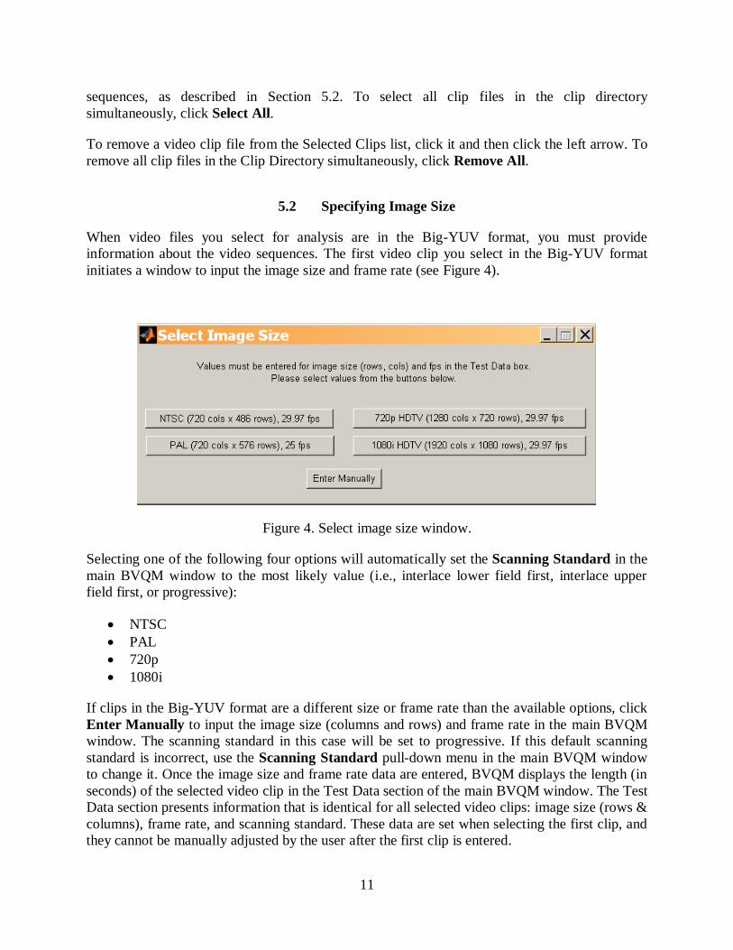
5.2 Specifying Image Size
When video files you select for analysis are in the Big-YUV format, you must provide
information about the video sequences. The first video clip you select in the Big-YUV format
initiates a window to input the image size and frame rate (see Figure 4).
Figure 4. Select image size window.
Selecting one of the following four options will automatically set the Scanning Standard in the
main BVQM window to the most likely value (i.e., interlace lower field first, interlace upper
field first, or progressive):
NTSC
PAL
720p
1080i
If clips in the Big-YUV format are a different size or frame rate than the available options, click
Enter Manually to input the image size (columns and rows) and frame rate in the main BVQM
window. The scanning standard in this case will be set to progressive. If this default scanning
standard is incorrect, use the Scanning Standard pull-down menu in the main BVQM window
to change it. Once the image size and frame rate data are entered, BVQM displays the length (in
seconds) of the selected video clip in the Test Data section of the main BVQM window. The Test
Data section presents information that is identical for all selected video clips: image size (rows &
columns), frame rate, and scanning standard. These data are set when selecting the first clip, and
they cannot be manually adjusted by the user after the first clip is entered.

12
To change the image size or frame rate, click the Enter Manually button. This will clear the
current values and query you to reenter them. The scanning standard will be reset to the most
appropriate value based upon the new data entered.
Important Note: All selected clip files must have the same image size, frame rate and scanning
standard. BVQM initializes the default scanning standard value depending on the identified
image size and frame rate. However, this value may be incorrect for some video capture systems.
Always verify the scanning standard and manually change it as necessary.
5.3 Specifying Video Clip Data
The Video Clip Data section at the bottom of the main BVQM window contains information for
the clip file currently selected in the Selected Files listbox. When standard file names are used,
values for Scene, HRC, and the Original Clip checkbox display for each clip file as you click
the Browse Files left or right arrows. Alternatively, you can double-click the file in the Selected
Files listbox to select the file. When non-standard file names are loaded, you will be asked to
enter the scene and HRC values manually in a pop-up window for each video clip file. Ensure
that you identify Scene and HRC values accurately for each clip file, otherwise BVQM will not
be able to accurately estimate the calibration or quality of the selected video clips and HRCs.
Once you have selected the clip files you want and are satisfied with all parameters for the clips,
click Continue in the lower-right corner of the main BVQM window. BVQM will display the
calibration and model selection window (see Section 6) unless there is an error or if some of the
clips exceed 15 seconds in length.
When clips exceed 15 seconds in length, you are presented with the 15 seconds maximum
window shown in Figure 5. If you select Truncate, only the first 15 seconds of the clips will be
used by BVQM. If you select Parse, the parse window (Figure 6) displays and you can enter the
parsing parameters. The parse length controls the length of the parsed clips (in seconds) while
the parse shift specifies the shift (in seconds) between successively parsed clips. You can use the
parse shift parameter to create parsed clips with amounts you define of overlap, zero overlap, or
even missing segments between successively parsed clips. The scene names of the parsed clips
will be the original scene names appended with their end time (in seconds).
Figure 5. 15 seconds maximum window.

13
Figure 6. Parse window.

14
6. SPECIFYING CALIBRATION AND A VIDEO QUALITY MODEL
The next step in the video clip analysis setup process is to specify a calibration algorithm and a
video quality model (see Figure 7). See Sections 6.1 and 6.3 for information about calibration
and video quality model options, respectively.
Figure 7. Calibration and model selection window.

15
After you have made your selections, click Continue in the Calibration and Model Selection
window to start the computations. If you select any calibration option that uses reduced
reference, full reference, or Peak Signal to Noise Ratio (PSNR), pop-up windows display
additional options described in Section 6.2. If you have selected any of the manual calibration
options, additional input will also be required (see section 7).
Once BVQM begins processing the clips, a status bar shows the relative time until completion of
the calibration and model algorithms. The processing time is highly dependent on the number of
clips selected, their time durations, and their spatial resolution. When BVQM finishes
processing, the Video Quality Measurement Results window displays the video quality metric
results of the batch processing. See Section 8 for more information on viewing and reporting
results.
6.1 Calibration Selection
Calibration attempts to remove impairments from the processed video sequence that viewers
either don’t see or don’t care about. Impairments include, for example, a spatial shift of the entire
video sequence a few pixels to the right. If an HRC has induced such a shift, and it is not
removed prior to model calculation, then the model’s quality estimates may be significantly less
accurate (i.e., the model will normally over-penalize in this case).
The Full Reference and Reduced Reference calibration algorithms become more accurate when
you run BVQM with multiple scenes associated with the same HRC. Some calibration
parameters are systematic — that is, constant for each HRC — and thus, improved accuracy is
obtained by simultaneously examining all scenes associated with a single HRC. Preferably, a
minimum of five unique scenes should be run through each HRC to obtain robust calibration
estimates; and preferably the scenes should be visually very different (e.g., varying amounts of
motion, varying amounts of spatial detail, varying patterns and textures and colors). The ordering
of the scenes for each HRC will not affect the results.
The Calibration and Model Selection window provides the following calibration options:
No Calibration Performs no calibration. BVQM assumes that the start frames in original
and processed video files align temporally, and runs the model with default calibration
values. This assumes that the processed video file is perfectly calibrated.
Manual Calibration Reads the calibration quantities from a spreadsheet that has been
written by BVQM and then modified by the user (see Section 7).
Temporal Registration after Manual Calibration Reads the calibration quantities from
a spreadsheet written by BVQM and modified by you (see Section 7), and then performs
only temporal registration. After you click Continue, you must select either the full
reference or reduced reference algorithm for computation of temporal registration.
Temporal Registration and Valid Region Only Performs only the temporal registration
and valid region estimation algorithms (i.e., no spatial registration, scaling, gain, or
offset). After you click Continue, you must select either the full reference or reduced
reference algorithm for computation of temporal registration.
16
Reduced Reference Calibration Version 1 Performs reduced reference calibration as
given in [2]. These algorithms use random processes, which may yield slightly different
results from one run to another. You will be prompted for the temporal registration
uncertainty (the default value is plus or minus one second) and asked whether spatial
scaling should be performed (the default selection is “no”; see Section 6.2). The reduced
reference algorithms can exhibit poor behavior for scenes with nearly constant motion
throughout the entire clip (e.g., a smooth continuous pan). If problems occur, try using
full reference calibration instead. The reduced reference calibration’s spatial scaling
estimation algorithm is valuable for HRCs that perform spatial scaling (i.e., stretching or
shrinkage) of the image. This algorithm may exhibit poor behavior for some types of
scene content and thus should only be used when five or more video scenes are
associated with each HRC.
Reduced Reference Calibration Version 2 Performs reduced reference calibration as
given in [3] and [4]. Version 2 is slightly improved from version 1 and includes
estimation (but not removal) of chrominance (Cb, Cr) gain and level offset. You will be
prompted for the temporal registration uncertainty (the default value is plus or minus one
second) and asked whether spatial scaling should be performed (the default selection is
“no”; see Section 6.2).
Full Reference Calibration Performs full reference calibration as given in ANSI
T1.801.03-2003 [5], ITU-T J.144 (03/04) [6], and ITU-R BT.1683 (06/04) [7]. You will
be prompted for the temporal registration uncertainty (see Section 6.2). The default value
is plus or minus one second. This calibration option cannot detect spatial scaling of the
processed video.
Peak Signal to Noise Ratio Performs PSNR full reference calibration as given in ITU-T
J.340 [8] [9]. You will be prompted for the PSNR calibration options: fraction sampled,
spatial uncertainty, and temporal uncertainty (see Section 6.2). The default values are 0.1,
plus or minus 3 pixels, and plus or minus one second, respectively. You should use the
smallest possible spatial and temporal search uncertainties that will properly calibrate
your video clips as increasing these uncertainties drastically increases the required run
time.
ITU-T J.244 followed by ITU-T J.340 Performs reduced reference calibration version 2,
followed by PSNR calibration. You will be prompted to enter optional information for
both the ITU-T J.244 calibration, which is performed first, and the ITU-T J.340
calibration, which uses the results from the ITU-T J.244 calibration as its starting point.
The default fraction sampled, spatial uncertainty, and temporal uncertainty for the ITU-T
J.340 calibration is 0.1, plus or minus 1 pixel, and plus or minus 0.5 seconds.
respectively. The basic idea behind this calibration option is to perform PSNR calibration
for clips with large spatial and temporal shifts (and possible spatial scaling) without the
long run times.
ITU-T J.144 followed by ITU-T J.340 Performs full reference calibration, followed by
PSNR calibration. You will be prompted to enter optional information for both the ITU-T
J.144 calibration, which is performed first, and the ITU-T J.340 calibration, which uses
the results from the ITU-T J.144 calibration as its starting point. The default fraction
sampled, spatial uncertainty, and temporal uncertainty for the ITU-T J.340 calibration is
0.1, plus or minus 1 pixel, and plus or minus 0.5 seconds. respectively. The basic idea

17
behind this calibration option is to perform PSNR calibration for clips with large spatial
and temporal shifts without the long run times.
6.2 Additional Calibration Options
If you select Full Reference or Reduced Reference calibration in the Calibration and Model
Selection window, dialogue windows provide temporal registration uncertainty and spatial
scaling options. Temporal registration uncertainty indicates the maximum expected uncertainty
(in seconds) of the temporal registration between the processed and original video files.
Temporal registration uncertainty is bi-directional (i.e., plus or minus). The value specified
should be slightly larger than the maximum delay expected or the temporal registration routines
will not be able to find the proper delay. The default value for the temporal registration
uncertainty is plus or minus one second.
Spatial scaling issues may not be obvious when a processed video sequence is viewed. Spatial
scaling problems may produce video quality metric scores that indicate significantly lower
quality than expected from a visual inspection of the video. BVQM does not perform spatial
scaling estimation by default for the reduced reference calibration (you must select it manually in
the pop-up window). Spatial scaling correction is only available with reduced reference
calibration.
If one of the three calibration options that use PSNR calibration are selected, then the user will
also be given the option of entering fraction sampled, spatial uncertainty (in both the x and y
directions), and temporal uncertainty. The fraction sampled is the fraction of pixels in the video
scene that are used to compute the gain and level offset. Gain and offset are computed using a
least squares fit and using all the pixels requires a lot of memory. Spatial uncertainty is specified
in plus or minus how many pixels you want to search. The user can enter x and y uncertainties
separately. Your processed video clips must have spatial shifts less than or equal to what is
entered. Likewise, the video processed clips must have temporal shifts less than or equal to what
is entered. Temporal uncertainty is specified in seconds.
6.3 Video Quality Model Selection
The video quality models estimate the mean of a group’s opinions of the overall quality
experience when watching a video clip. The Calibration and Model Selection window provides
the following video quality models:
NTIA General Model The NTIA General Model has been standardized by ANSI [5] and
included in two ITU Recommendations ([6] and [7]). The General Model provides a set
of parameters and parameter weightings you can use to accurately evaluate video quality
over a wide range of quality and bit rates. The NTIA General Model is also fully
documented in [10] and summarized in [11].
Low Bandwidth Model This model uses reduced reference features that minimize the
required IP network bandwidth (for Rec. 601 video [1], approximately 10 kbits/sec are
required to transmit the reduced reference features). The run-speed of this model is

18
comparable to that of the General Model. An overview of the Low Bandwidth Model is
given in [12]. This model is approximately as fast as the NTIA General Model.
Developer’s Model The Developer’s Model minimizes CPU usage and is an
approximation of the NTIA General Model. This model is approximately six times faster
than the NTIA General Model. The Developer’s model is fully documented in [10],
which includes accuracy comparisons for the two models.
Television Model This model is specifically optimized for higher video quality typically
found in television applications (bit rates greater than 1.5 Mbits/sec). This model is fully
documented in [10].
Video Conferencing Model This model is specifically optimized for lower video quality
typically found in video conferencing applications (bit rates from 10Kbits/sec to 1.5
Mbits/sec). This model is fully documented in [10].
Fast Low Bandwidth Model This model minimizes CPU usage and is an approximation
of the Low Bandwidth Model.3 This model is approximately four times faster than the
Low Bandwidth Model. An overview of the Fast Low Bandwidth Model is given in [13].
The Fast Low Bandwidth Model was included in ITU-T J.249 [14].
PSNR This model computes Peak Signal to Noise Ratio (PSNR) using either a peak
signal level of 235 (which corresponds to ITU-R Rec. BT-601 white level), or 255 (which
corresponds to maximum white level). Note that the BVQM calibration only aligns
spatially to the nearest pixel. If sub-pixel shifts are present, they will not be corrected for
and hence PSNR might be lower than expected.
PSNR with Variable Frame Delay The PSNR_VFD model computes the PSNR of the
processed clip after Variable Frame Delay (VFD) matching. Here, the original clip’s
fields and/or frames are changed so as to match the processed fields and/or frames. Thus,
PSNR_VFD is not sensitive to pure dropped and/or repeated frames since the original
will be made to look like the processed prior to calculation of PSNR. The VFD algorithm
is fully documented in [15] and PSNR_VFD is fully documented in [16]. When
PSNR_VFD is selected, a pop-up window allows the user to select the temporal
uncertainty for the VFD estimation and the peak signal level (235 or 255). To assure
accuracy in the PSNR_VFD calculation, the original video clip must contain all content
shown in the processed video clip. For example, the processed clip must not have a scene
cut at the end that is not included in the original.
VQM with Variable Frame Delay This option selects the VQM_VFD model, which is
fully documented in [17]. The VQM_VFD model includes VFD estimation and removal,
VFD parameters that quantify perceptual distortions due to VFD, viewing distance, and a
neural network for performing the output mapping of parameter values to estimated
subjective mean opinion scores. When the VQM_VFD model is selected, a pop-up
window allows the user to select the temporal uncertainty for the VFD estimation and the
viewing distance (in picture heights). To assure accuracy in the PSNR_VFD calculation,
3 The Fast Low Bandwidth model differs from the Low Bandwidth model in the following ways: (1) Each second of
video is averaged prior to calculating the spatial information features, (2) the temporal information features use only
the luminance image, and (3) the temporal information features use a sub-sampling of pixels rather than the entire
image.

19
the original video clip must contain all content shown in the processed video clip. For
example, the processed clip must not have a scene cut at the end that is not included in
the original.
20
7. MANUAL CALIBRATION SETTINGS
If you select one of the manual calibration options on the calibration and model selection
window (Figure 7) and click Continue, BVQM will prompt for manual calibration settings.
BVQM first computes the default manual calibration values and writes these to three comma-
separated value (CSV) files called:
LoadManualCalibration_sheet1.csv,
LoadManualCalibration_sheet2.csv, and
LoadManualCalibration_sheet3.csv,
in the results directory that was selected in Figure 1. You must edit these CSV files with your
manual settings before continuing with the execution of BVQM. The three CSV files contain the
HRC, scene, and clip calibration information, respectively. The next three sections will describe
the calibration values for each sheet.
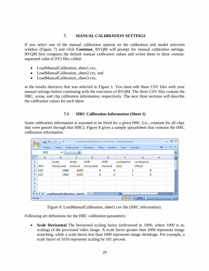
7.1 HRC Calibration Information (Sheet 1)
Some calibration information is assumed to be fixed for a given HRC (i.e., constant for all clips
that were passed through that HRC). Figure 8 gives a sample spreadsheet that contains the HRC
calibration information.
Figure 8. LoadManualCalibration_sheet1.csv file (HRC information).
Following are definitions for the HRC calibration parameters:
Scale Horizontal The horizontal scaling factor (referenced to 1000, where 1000 is no
scaling) of the processed video image. A scale factor greater than 1000 represents image
stretching, while a scale factor less than 1000 represents image shrinkage. For example, a
scale factor of 1010 represents scaling by 101 percent.
21
Scale Vertical The vertical scaling factor (referenced to 1000, where 1000 is no scaling)
of the processed video image. A scale factor greater than 1000 represents image
stretching while a scale factor less than 1000 represents image shrinkage. For example, a
scale factor of 1010 represents scaling by 101 percent.
Shift Horizontal Specifies the horizontal shift (in pixels) between the fields (interlace) or
frames (progressive) of the processed video with respect to the original video. Value must
be an integer. A positive horizontal shift is associated with a processed field or frame that
has been moved to the right (with respect to the original) by that number of pixels.
Shift Vertical Specifies the vertical shift in frame lines of the processed video with
respect to the original video. Value must be an integer. A positive vertical shift is
associated with a processed field or frame that has been moved down (with respect to the
original) by that number of frame lines.
Luminance Gain A multiplicative scaling factor applied by the HRC to all pixels of the
luminance image (i.e., the Y component). Gain of the luminance signal is commonly
known as contrast. System gains greater than 1.0 may produce processed video that has
amplitude clipping (clipped whites).
Luminance Offset An additive factor applied by the HRC to all pixels of the luminance
image (i.e., the Y component). Offset of the luminance signal is commonly known as
brightness. Offset is specified in Rec. 601 quantization levels, where an offset of 1 is one
quantization level. This is a real number that can be either positive or negative. Large
system offsets (positive or negative) may produce processed video that has amplitude
clipping at the high or low end (clipped whites or clipped blacks).
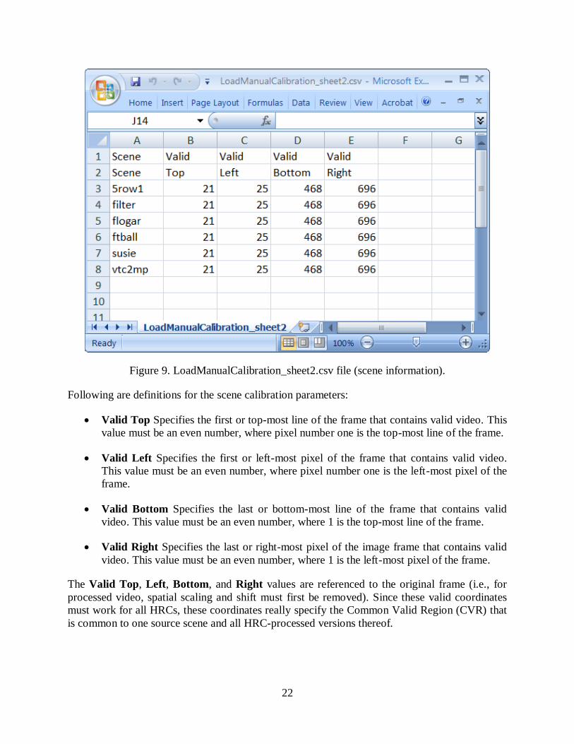
7.2 Scene Calibration Information (Sheet 2)
Some calibration information is assumed to be fixed for a given scene regardless of which HRC
the scene was passed through. Figure 9 gives a sample spreadsheet that contains the scene
calibration information.
22
Figure 9. LoadManualCalibration_sheet2.csv file (scene information).
Following are definitions for the scene calibration parameters:
Valid Top Specifies the first or top-most line of the frame that contains valid video. This
value must be an even number, where pixel number one is the top-most line of the frame.
Valid Left Specifies the first or left-most pixel of the frame that contains valid video.
This value must be an even number, where pixel number one is the left-most pixel of the
frame.
Valid Bottom Specifies the last or bottom-most line of the frame that contains valid
video. This value must be an even number, where 1 is the top-most line of the frame.
Valid Right Specifies the last or right-most pixel of the image frame that contains valid
video. This value must be an even number, where 1 is the left-most pixel of the frame.
The Valid Top, Left, Bottom, and Right values are referenced to the original frame (i.e., for
processed video, spatial scaling and shift must first be removed). Since these valid coordinates
must work for all HRCs, these coordinates really specify the Common Valid Region (CVR) that
is common to one source scene and all HRC-processed versions thereof.

23
7.3 Clip Calibration Information (Sheet 3)
Some calibration information may change from clip to clip (e.g., temporal alignment). This
information must therefore be entered for each clip being processed. Figure 10 gives a sample
spreadsheet that contains the clip calibration information.
Figure 10. LoadManualCalibration_sheet3.csv file (clip information).
Following are definitions for the scene calibration parameters:
File First Valid Frame Number of the first frame to consider in the video file for
the given clip. The value that is auto-populated by BVQM will depend on the clip length
and parsing options that have been selected (for clips over 15 seconds). You can use the
File First Valid Frame to discard the beginning of the video file from consideration
without editing the file. For example, the first second may not be of interest or may
contain atypical video quality (e.g., very low quality due to video codec initialization).
File Last Valid Frame Number of the last frame to consider in the video file for the
given clip. The value that is auto-populated by BVQM will depend on the clip length and
parsing options that have been selected (for clips over 15 seconds).

24
Temporal Start Frame The alignment start point of the video clip, in frames, where 1
is the first frame in the file. The “Temporal Start Frame” of the processed clip time aligns
to the “Temporal Start Frame” of the original clip. If you selected the Temporal
Registration after Manual Calibration option, this value will be estimated by the temporal
registration routines of BVQM and output to the results report and exported spreadsheet
files (see Section 8). The “Temporal Start Frame” is always greater than or equal to the
“File First Valid Frame” and provides the first frame over which the video quality
estimate will be computed.
Temporal Stop Frame The alignment stop point of the video clip, in frames, where 1 is
the first frame in the file. The “Temporal Stop Frame” of the processed clip time aligns to
the “Temporal Stop Frame” of the original clip. If you selected the Temporal Registration
after Manual Calibration option, this value will be estimated by the temporal registration
routines of BVQM and output to the results report and exported spreadsheet files (see
Section 8). The “Temporal Stop Frame” is always less than or equal to the “File Last
Valid Frame” and provides the last frame over which the video quality estimate will be
computed.
MOS Mean Opinion Score (MOS) of the clip, if known. This can be used to generate
plots and linear fits of MOS versus VQM from the VQM results window (Figure 11).
7.4 Error Troubleshooting
When you have finished entering all of the manual calibration settings, save the CSV files and
continue the execution of BVQM. BVQM will check the manually entered calibration values for
errors and inconsistencies (e.g., if the length of the time aligned original and processed video
clips are not identical) and the appropriate warnings will be displayed along with information
about what to correct before continuing. Keep in mind: the following restrictions apply to video
clips chosen for a single run of the BVQM software:
For each processed video clip, there must be a matching original video clip with the same
scene name and similar time extent (e.g., visually, the sequence starts and stops at
approximately the same point).
There must be one and only one original video clip for each scene. The “original clip”
check button will automatically be selected for all original clips.
All video clips must have the same frame rate and image size.
All video clips must have the same scanning standard (i.e., “progressive,” “interlace
lower field first,” or “interlace upper field first”).
All video files must be saved in one of the file formats specified in Section 4.1.

25

26
8. VIEWING RESULTS
The Video Quality Measurement Results window displays the results from the test. Results may
be viewed either graphically (see Figure 11), as text reports, or as exported spreadsheet files.
Use the pull-down menu in the top half of the results window to select a specific graphical
summary to view. For example, you can select summaries to show video quality vs. clip, HRC,
or scene. You can also view detailed results for each individual clip by selecting Details: Single-
Clip Results from the pull-down menu and then selecting the clip of interest. Results graphs
show the overall video quality metric score along with the parameters that comprise the chosen
model, such as si_loss, hv_gain, etc. To export the graph that is currently displayed, click Export
Graph below the pull-down menu.
The Report part of the results window displays the data in text format. In the Report Type
section, click Summary or Detailed to view either the summary report or the detailed report.
BVQM saves all data in the results directory. The full path and filename of the report display
above the report text.
To save CSV results files, click Export to comma-separated value (CSV). Five CSV results
files will be written to the results directory (selected in Figure 1). If the scenes followed the
“scene_hrc” naming convention, these CSV results files will be named as follows:
bvqm_calibration_date@time_sheet1.csv
bvqm_calibration_date@time_sheet2.csv
bvqm_calibration_date@time_sheet3.csv
The calibration files contain the file calibration values that were used by BVQM (in a format
identical to that of the LoadManualCalibration files described in Section 7). The clips file
contains a summary of all the clip information (organized clip-by-clip), and the model file
contains the VQM scores and their associated quality parameter values.
If the user selected one of the VFD models (PSNR_VFD or VQM_VFD), then one additional
CSV file is output that contains the VFD alignment information and the processed frames that
were used to compute the model. This sheet is called:
bvqm_model_date@time_vfd.csv
If the PSNR_VFD model was selected, the additional sheet also contains PSNR_VFD, Par1, and
Par2, as described in [16].

27
Figure 11. Video Quality Measurement Results window.

28
9. EXITING BVQM
To quit BVQM from the Video Quality Measurement Results window (Figure 11), click Exit
You will be asked if you want to save intermediate results before quitting. The intermediate
results consist of the temporary files and directories that were created and used during processing
(e.g., quality features stored in *.mat MATLAB files). If you choose to save the intermediate
results, they will be stored in the results directory. Choosing not to save intermediate results will
erase all of the temporary files and directories that were created during processing. The summary
and detail reports will remain in the results directory.
You can quit BVQM by clicking the Exit button or by clicking the X in the upper-right corner of
the window. These exit options are available on the main BVQM window (Figure 3), the
Calibration and Model Selection window (see Figure 5), and the Video Quality Measurement
Results window (see Figure 7).
Clicking the X in the upper-right corner of a pop-up window will take you back to the previous
window. For example, if you select the PSNR model and click the Next button, a pop-up
window appears (asking you to specify peak signal level). If you close that pop-up window, you
will return to the Calibration and Model Selection window.

29
10. KNOWN ISSUES
Following is a list of the known issues in the BVQM software.
Issue # Description
1. Out of Memory. Insufficient memory may cause BVQM to fail during processing.
a. Windows XP: BVQM can never have more than 2GB of memory when running
under Windows XP.
Modifying your computer’s memory usage performance options may increase the
amount of contiguous memory available to BVQM. Follow these steps to perform
this modification: a) Right-click My Computer, and select Properties. b) In the
System Properties window that appears, click the Advanced tab, then click
Settings in the Performance section. c) In the Performance Options window that
appears, click the Advanced tab, then in the Memory Usage section, select
System cache and click OK. d) Reboot your computer.
If this does not take care of the problem, upgrade to Windows 7 64-bit and install
more RAM memory in your computer.
b. Windows 7: Install more RAM memory in your computer.
2. Clicking a file in the Selected Files list box of the main BVQM window (see Figure 3)
does not update the Video Clip Data section of the main BVQM window even though the
clip appears to be selected. To update the Video Clip Data section, either double-click the
file name in the Selected Files list box, or use the Browse Files arrow buttons in the
Video Clip Data box.
3. When many clips are processed, the results graphs may not display properly.
4. Processing a set of video files through BVQM (in a single run) that contain different fps,
image cols, image rows or scanning standards is not supported by the BVQM software.
BVQM will use the fps, image cols, and image rows of the first file that is selected and
produce erroneous results for the clips that have different fps, image cols, image rows or
scanning standards.
5. BVQM cannot read compressed AVI files.
6. BVQM cannot reliably detect whether or not a file with the “.yuv” extension contain the
4:2:2 big-YUV format. If BVQM is given files in 4:2:0 big-YUV format, the program
may run but it will produce erroneous results.
30
11. ACKNOWLEDGMENTS
The authors would like to thank Mark A. McFarland for all his contributions to the BVQM
software and documentation.

31
12. REFERENCES
[1] ITU-R Recommendation BT.601, “Encoding parameters of digital television for studios,”
Recommendations of the ITU, Radiocommunication Sector.
[2] M. Pinson and S. Wolf, “Reduced reference video calibration algorithms,” NTIA Report
TR-06-433a, Jul. 2006. Available at www.its.bldrdoc.gov/publications/vqr/.
[3] M. Pinson and S. Wolf, “Reduced reference video calibration algorithms,” NTIA Report
TR-07-433b, Nov. 2007. Available at www.its.bldrdoc.gov/publications/vqr/.
[4] ITU-T Recommendation J.244, “Full reference and reduced reference calibration methods
for video transmission systems with constant misalignment of spatial and temporal domains
with constant gain and offset,” Recommendations of the ITU, Telecommunication
Standardization Sector.
[5] ANSI T1.801.03 – 2003, “American National Standard for Telecommunications – Digital
transport of one-way video signals – Parameters for objective performance assessment,”
American National Standards Institute. Available at www.ansi.org.
[6] ITU-T Recommendation J.144, “Objective perceptual video quality measurement
techniques for digital cable television in the presence of a full reference,” Recommendations
of the ITU, Telecommunication Standardization Sector.
[7] ITU-R Recommendation BT.1683, “Objective perceptual video quality measurement
techniques for standard definition digital broadcast television in the presence of a full
reference,” Recommendations of the ITU, Radiocommunication Sector.
[8] ITU-T Recommendation J.340, “Reference algorithm for computing peak signal to noise
ratio of a processed video sequence with compensation for constant spatial shifts, constant
temporal shift, and constant luminance gain and offset,” Recommendations of the ITU,
Telecommunication Standardization Sector.
[9] S. Wolf and M. Pinson, “Reference Algorithm for Computing Peak Signal to Noise Ratio
(PSNR) of a Video Sequence with a Constant Delay,” ITU-T Study Group 9 Contribution
COM9-C6-E, Geneva, February 2-6, 2009. Available at
www.its.bldrdoc.gov/publications/vqr/.
[10] S. Wolf and M. Pinson, “Video quality measurement techniques,” NTIA Report 02-392,
Jun. 2002. Available at www.its.bldrdoc.gov/publications/vqr/.
[11] M. Pinson and S. Wolf, “A new standardized method for objectively measuring video
quality,” IEEE Transactions on Broadcasting, v. 50, n. 3, pp. 312-322, Sept. 2004.
Available at www.its.bldrdoc.gov/publications/vqr/.
[12] S. Wolf and M. Pinson, “Low bandwidth reduced reference video quality monitoring
system,” in Proc. First International Workshop on Video Processing and Quality Metrics

32
for Consumer Electronics, Scottsdale, Arizona, Jan. 23-25, 2005. Available at
www.its.bldrdoc.gov/publications/vqr/.
[13] S. Wolf and M. Pinson, “Fast Low Bandwidth Video Quality Model (VQM) Description
and Reference Code,” ITU-T Study Group 9 Contribution COM9-C5-E, Geneva, February
2-6, 2009. Available at www.its.bldrdoc.gov/publications/vqr/.
[14] ITU-T Recommendation J.249, “Perceptual video quality measurement techniques for
digital cable television in the presence of a reduced reference,” Recommendations of the
ITU, Telecommunication Standardization Sector.
[15] Stephen Wolf, “A Full Reference (FR) Method Using Causality Processing for Estimating
Variable Video Delays,” NTIA Technical Memorandum TM-10-463, Oct. 2009. Available
at www.its.bldrdoc.gov/publications/vqr/.
[16] Stephen Wolf, “Variable Frame Delay (VFD) Parameters for Video Quality Measurements,”
NTIA Technical Memorandum TM-11-475, Apr 2011. Available at
www.its.bldrdoc.gov/publications/vqr/.
[17] Stephen Wolf and Margaret Pinson, “Video Quality Model for Variable Frame Delay
(VQM_VFD),” NTIA Technical Memorandum TM-11-482, Sep. 2011. Available at
www.its.bldrdoc.gov/publications/vqr/.
FORM NTIA-29 U.S. DEPARTMENT OF COMMERCE (4-80) NAT’L. TELECOMMUNICATIONS AND INFORMATION ADMINISTRATION
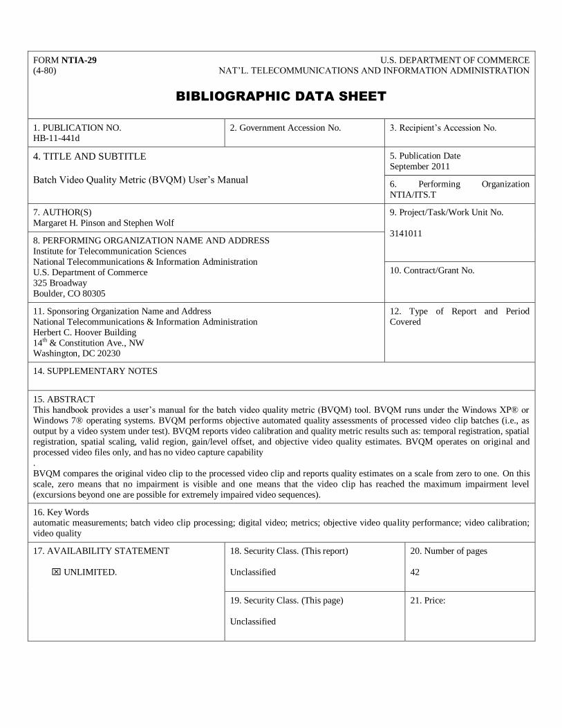
BIBLIOGRAPHIC DATA SHEET
1. PUBLICATION NO. HB-11-441d
2. Government Accession No.
3. Recipient’s Accession No.
4. TITLE AND SUBTITLE
Batch Video Quality Metric (BVQM) User’s Manual
5. Publication Date
September 2011
6. Performing Organization
NTIA/ITS.T
7. AUTHOR(S)
Margaret H. Pinson and Stephen Wolf
9. Project/Task/Work Unit No.
3141011 8. PERFORMING ORGANIZATION NAME AND ADDRESS
Institute for Telecommunication Sciences
National Telecommunications & Information Administration
U.S. Department of Commerce
325 Broadway
Boulder, CO 80305
10. Contract/Grant No.
11. Sponsoring Organization Name and Address
National Telecommunications & Information Administration
Herbert C. Hoover Building
14th & Constitution Ave., NW Washington, DC 20230
12. Type of Report and Period
Covered
14. SUPPLEMENTARY NOTES
15. ABSTRACT
This handbook provides a user’s manual for the batch video quality metric (BVQM) tool. BVQM runs under the Windows XP® or
Windows 7® operating systems. BVQM performs objective automated quality assessments of processed video clip batches (i.e., as
output by a video system under test). BVQM reports video calibration and quality metric results such as: temporal registration, spatial
registration, spatial scaling, valid region, gain/level offset, and objective video quality estimates. BVQM operates on original and
processed video files only, and has no video capture capability
.
BVQM compares the original video clip to the processed video clip and reports quality estimates on a scale from zero to one. On this
scale, zero means that no impairment is visible and one means that the video clip has reached the maximum impairment level
(excursions beyond one are possible for extremely impaired video sequences).
16. Key Words automatic measurements; batch video clip processing; digital video; metrics; objective video quality performance; video calibration;
video quality
17. AVAILABILITY STATEMENT
UNLIMITED.
18. Security Class. (This report)
Unclassified
20. Number of pages
42
19. Security Class. (This page)
Unclassified
21. Price:
NTIA FORMAL PUBLICATION SERIES
NTIA MONOGRAPH (MG) A scholarly, professionally oriented publication dealing with state-of-the-art research or an authoritative treatment of a broad area. Expected to have long-lasting value.
NTIA SPECIAL PUBLICATION (SP) Conference proceedings, bibliographies, selected speeches, course and instructional materials, directories, and major studies mandated by Congress.
NTIA REPORT (TR) Important contributions to existing knowledge of less breadth than a monograph, such as results of completed projects and major activities. Subsets of this series include:
NTIA RESTRICTED REPORT (RR) Contributions that are limited in distribution because of national security classification or Departmental constraints.
NTIA CONTRACTOR REPORT (CR)
Information generated under an NTIA contract or grant, written by the contractor, and considered an important contribution to existing knowledge.
JOINT NTIA/OTHER-AGENCY REPORT (JR) This report receives both local NTIA and other agency review. Both agencies’ logos and report series numbering appear on the cover.
NTIA SOFTWARE & DATA PRODUCTS (SD) Software such as programs, test data, and sound/video files. This series can be used to transfer technology to U.S. industry.
NTIA HANDBOOK (HB)
Information pertaining to technical procedures, reference and data guides, and formal user’s manuals that are expected to be pertinent for a long time.
NTIA TECHNICAL MEMORANDUM (TM)
Technical information typically of less breadth than an NTIA Report. The series includes data, preliminary project results, and information for a specific, limited audience.
For information about NTIA publications, contact the NTIA/ITS Technical Publications Office at 325 Broadway, Boulder, CO, 80305 Tel. (303) 497-3572 or e-mail [email protected].


