NASA Technical Memorandum 106453 IEPC-93-1S1 A Large High Vacuum, High Pumping Speed Space Simulation Chamber for Electric Propulsion Stanley P. Grisnik National Aeronautics and Space Administration Lewis Research Center Cleveland, Ohio and James E. Parkes Sverdrup Technology, Inc. Lewis Research Center Group Brook Park, Ohio Prepared for the 23rd International Electric Propulsion Conference cosponsored by the AIAA, AIDAA, DGLR, and JSASS Seattle, Washington, September 13-16,1993 NI\5/\ NASA Technical Memorandum 106453 IEPC-93-1S1 A Large High Vacuum, High Pumping Speed Space Simulation Chamber for Electric Propulsion Stanley P. Grisnik National Aeronautics and Space Administration Lewis Research Center Cleveland, Ohio and James E. Parkes Sverdrup Technology, Inc. Lewis Research Center Group Brook Park, Ohio Prepared for the 23rd International Electric Propulsion Conference cosponsored by the AIAA, AIDAA, DGLR, and JSASS Seattle, Washington, September 13-16,1993 NI\5/\ https://ntrs.nasa.gov/search.jsp?R=19940021639 2018-06-06T20:29:47+00:00Z
Transcript
NASA Technical Memorandum 106453 IEPC-93-1S1
A Large High Vacuum, High Pumping Speed Space Simulation Chamber for Electric Propulsion
Stanley P. Grisnik National Aeronautics and Space Administration Lewis Research Center Cleveland, Ohio
and
James E. Parkes Sverdrup Technology, Inc. Lewis Research Center Group Brook Park, Ohio
Prepared for the 23rd International Electric Propulsion Conference cosponsored by the AIAA, AIDAA, DGLR, and JSASS Seattle, Washington, September 13-16,1993
NI\5/\
NASA Technical Memorandum 106453 IEPC-93-1S1
A Large High Vacuum, High Pumping Speed Space Simulation Chamber for Electric Propulsion
Stanley P. Grisnik National Aeronautics and Space Administration Lewis Research Center Cleveland, Ohio
and
James E. Parkes Sverdrup Technology, Inc. Lewis Research Center Group Brook Park, Ohio
Prepared for the 23rd International Electric Propulsion Conference cosponsored by the AIAA, AIDAA, DGLR, and JSASS Seattle, Washington, September 13-16,1993
A LARGE HIGH VACUUM, HIGH PUMPING SPEED SPACE SIMULATION CHAMBER FOR ELECTRIC PROPULSION
Stanley P. Grisnik National Aeronautics and Space Administration
Lewis Research Center Cleveland, Ohio 44135
and
James E. Parkes Sverdrup Technology, Inc.
Lewis Research Center Group Brook Park, Ohio 44142
Abstract
Testing high power electric propulsion devices poses unique requirements on space simulation facilities. Very high pumping speeds are required to maintain high vacuum levels while handling large volumes of exhaust products. These pumping speeds are significantly higher than those available in most existing vacuum facilities. There is also a requirement for relatively large vacuum chamber dimensions to minimize facility wall/thruster plume interactions and to accommodate far field plume diagnostic measurements.
A 4.57 m (15 ft) diameter by 19.2 m (63 ft) long vacuum chamber at NASA Lewis Research Center is described in this paper. The chamber utilizes oil diffusion pumps in combination with cryopane1s to achieve high vacuum pumping speeds at high vacuum levels. The facility is computer controlled for all phases of operation from start-up, through testing, to shutdown. The computer control system increases the utilization of the facility and reduces the manpower requirements needed for facility operations.
Introduction
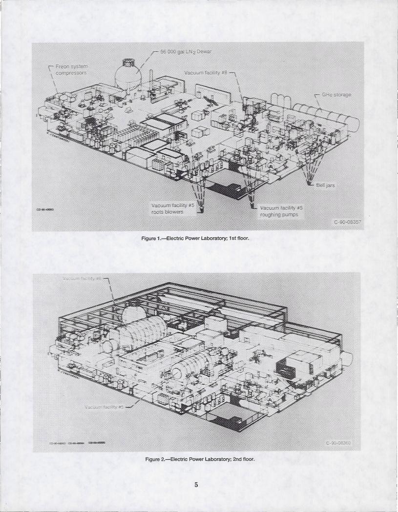
The NASA Lewis 4.57 m (15 ft) diameter by 19.2 m (63 ft) long vacuum chamber (Vacuum Facility number 5) is located in the Electric Power Laboratory (Figs. 1 and 2). Vacuum Facility number 5 was originally designed and built for ion and plasma thruster research along with spacecraft and spacecraft component testing. 1
Its use today has expanded to encompass all types of electric propulsion testing in addition to tests of photovoltaic and space station components.
Through computer control, the facility is able to monitor its health and take corrective action as needed. This reduces the likelihood of facility damage from equipment failure or improper operation. Major equipment malfunctions and/or facility shutdowns result in immediate notification of the proper personnel to take action to prevent damage to the facility or test hardware. Graphic panels with an annunciator system display the current status of the vacuum pumps, gaseous and liquid nitrogen systems, gaseous helium system, propellant feed systems, and the refrigeration system.
Research testing can be controlled and monitored from either the facility control room or locally, near the individual test ports located at various places around the chamber. These test ports allow quick tum around time for experiment change-over by eliminating the need to pumpdown the main chamber.
The test ports, power supplies, and propellant supply systems are tied into a computer controlled interlock system. This system prevents improper or dangerous operation by personnel conducting hardware tests.
Chamber and SupPOrt Equipment Description
Vacuum Facility number 5 is constructed of 0.3175 cm (1/8 in.) thick 304 stainless steel internal cladding on a 1.428 cm (9/16 in.) thick mild steel outer shell. All internal facility specific components are fabricated
A LARGE HIGH VACUUM, HIGH PUMPING SPEED SPACE SIMULATION CHAMBER FOR ELECTRIC PROPULSION
Stanley P. Grisnik National Aeronautics and Space Administration
Lewis Research Center Cleveland, Ohio 44135
and
James E. Parkes Sverdrup Technology, Inc.
Lewis Research Center Group Brook Park, Ohio 44142
Abstract
Testing high power electric propulsion devices poses unique requirements on space simulation facilities. Very high pumping speeds are required to maintain high vacuum levels while handling large volumes of exhaust products. These pumping speeds are significantly higher than those available in most existing vacuum facilities. There is also a requirement for relatively large vacuum chamber dimensions to minimize facility wall/thruster plume interactions and to accommodate far field plume diagnostic measurements.
A 4.57 m (15 ft) diameter by 19.2 m (63 ft) long vacuum chamber at NASA Lewis Research Center is described in this paper. The chamber utilizes oil diffusion pumps in combination with cryopane1s to achieve high vacuum pumping speeds at high vacuum levels. The facility is computer controlled for all phases of operation from start-up, through testing, to shutdown. The computer control system increases the utilization of the facility and reduces the manpower requirements needed for facility operations.
Introduction
The NASA Lewis 4.57 m (15 ft) diameter by 19.2 m (63 ft) long vacuum chamber (Vacuum Facility number 5) is located in the Electric Power Laboratory (Figs. 1 and 2). Vacuum Facility number 5 was originally designed and built for ion and plasma thruster research along with spacecraft and spacecraft component testing. 1
Its use today has expanded to encompass all types of electric propulsion testing in addition to tests of photovoltaic and space station components.
Through computer control, the facility is able to monitor its health and take corrective action as needed. This reduces the likelihood of facility damage from equipment failure or improper operation. Major equipment malfunctions and/or facility shutdowns result in immediate notification of the proper personnel to take action to prevent damage to the facility or test hardware. Graphic panels with an annunciator system display the current status of the vacuum pumps, gaseous and liquid nitrogen systems, gaseous helium system, propellant feed systems, and the refrigeration system.
Research testing can be controlled and monitored from either the facility control room or locally, near the individual test ports located at various places around the chamber. These test ports allow quick tum around time for experiment change-over by eliminating the need to pumpdown the main chamber.
The test ports, power supplies, and propellant supply systems are tied into a computer controlled interlock system. This system prevents improper or dangerous operation by personnel conducting hardware tests.
Chamber and SupPOrt Equipment Description
Vacuum Facility number 5 is constructed of 0.3175 cm (1/8 in.) thick 304 stainless steel internal cladding on a 1.428 cm (9/16 in.) thick mild steel outer shell. All internal facility specific components are fabricated
I
. .
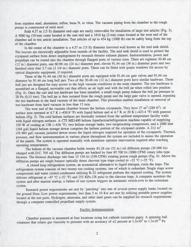
from stainless steel, aluminum, teflon, buna N, or viton. The vacuum piping from the chamber to the rough pumps is constructed of mild steeL
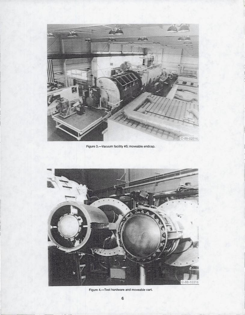
Both 4.57 m (15 ft) diameter end caps are easily removable for installation of large test articles (Fig. 3). A 9080 kg (lO-ton) crane located at the east end and a 1816 kg (2-ton) crane located at the west end of the chamber aid in test article installation. Test articles of up to 454 kg (1000 lb) can be safely hung from the top of the chamber.
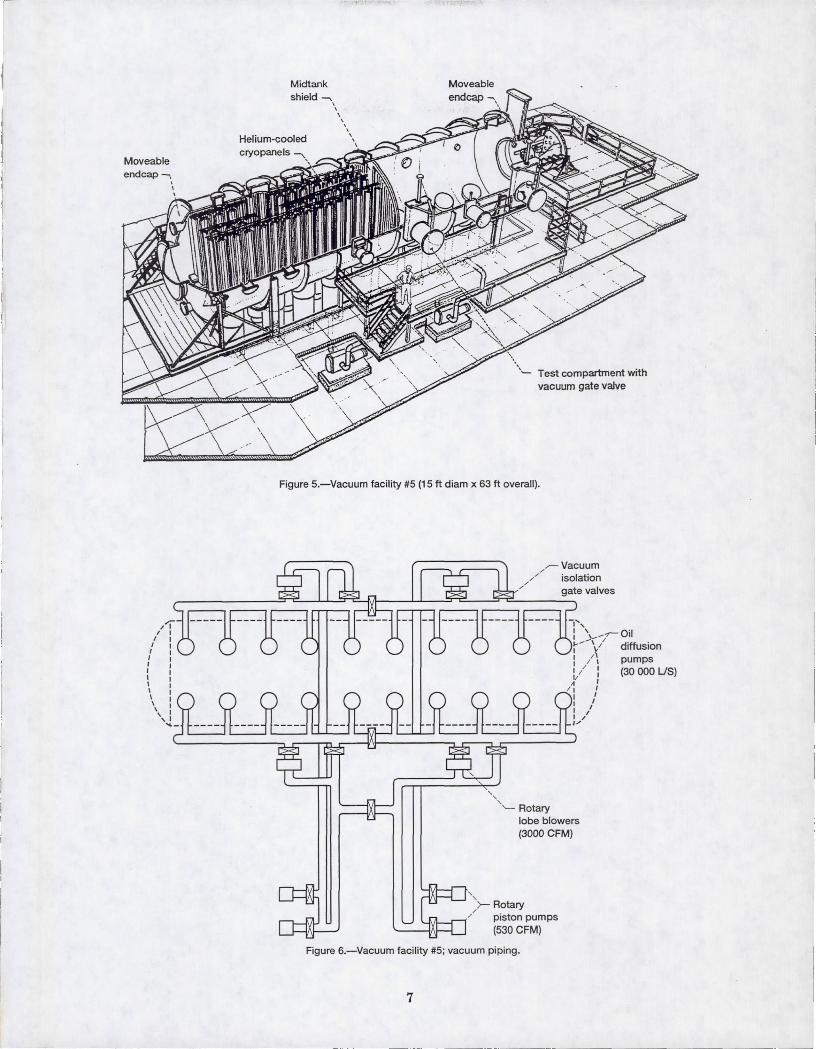
In the center of the chamber is a 4.57 m (15 ft) diameter louvered wall known as the mid tank shield. The louvers are electrically adjustable from outside of the facility. The mid tank shield is used to protect the cryopanel surface from direct impingement by research thruster exhaust plumes. Instrumentation, power and propellant can be routed into the chamber through flanged ports of various sizes. There are eighteen 30.48 cm (1 2 in.) diameter ports, one 60.96 cm (24 in.) diameter port, eleven 91.44 cm (36 in.) diameter ports and two hundred sixty four 5.7 cm (2 1/4 in.) diameter ports. These can be fitted with quartz windows for access by optical diagnostic equipment, if required.
Three of the 91.44 cm (36 in.) diameter ports are equipped with 91.44 cm gate valves and 91.44 cm diameter by 91.44 cm long bell jars. Two of the 30.48 cm (12 in.) diameter ports have similar hardware. These bell jars are designed for easy access to the high vacuum conditions in the main chamber. The test hardware is assembled on a flanged, moveable cart that affects an air tight seal with the bell jar when rolled into position (Fig. 4). Once the cart and test hardware has been installed, a small rough pump reduces the bell jar pressure to 20 Pa (0.15 torr). The bell jar is then isolated from the rough pump and the large gate valve is opened, exposing the test hardware to the hard vacuum of the main chamber. This procedure enables installation or removal of test hardware from hard vacuum in less than 15 min.
The west end of the vacuum chamber houses the helium cryopanels. They have 27 m2 (289 ft2). of surface area operated at 4.7 K (-450.9 OF) with liquid helium and at 4.7 K or 20 K (-423.4 OF) with gaseous helium (Fig. 5). The cold helium surfaces are thermally isolated from the ambient temperature facility walls with liquid nitrogen surfaces. A CTI ME1400 helium liquefaction/refrigeration machine capable of supplying 330 W of cooling at 13K (-436 OF), two helium storage tanks, two reciprocating compressors, and a 1000 liter (264 gal) liquid helium storage dewar comprise the helium portion of the cryopanel system. A 212 m3
(56 000 gal) vacuum jacketed dewar stores the liquid nitrogen required for operation of the cryopanels. Thermal, pressure, and flow instrumentation in various places throughout the system are included to assess the operation of the panels. The system is operated manually with minimum operator intervention required after reaching operating temperatures.
The bottom of the vacuum chamber holds twenty 81.28 cm (32 in.) oil diffusion pumps (30000 Us) charged with D.C. 705 oil. The diffusion pumps are backed by four 85 700 Us (3000 CFM) rotary lobe type blowers. The blowers discharge into four 15 150 Us (530 CFM) rotating piston rough pumps (Fig. 6). Above the diffusion pumps are single bounce optically dense chevron type traps cooled to -32 °C (-25 OF).
A closed loop refrigeration system, an economical alternative to liquid nitrogen, cools the traps. The refrigeration system consists of two twenty ton cooling systems, one of which is redundant. Single stage screw compressors and water cooled condensers utilizing R-22 refrigerant perform the required cooling. The system delivers refrigerant at -47 °C (-52 OF) and 255 KPa (38 psia) to the chevron traps. A computer monitors the system and after manual startup, a failure of one system triggers an automatic switch-over to the redundant system.
Research power requirements are met by "patching" into one of several power supply banks located on the ground floor. Low power requirements, less than 5 to 10 Kw are met by utilizing portable power supplies located at the test ports. Hydrogen, ammonia, and other inert gases can be supplied for research requirements through a computer controlled propellant supply system.
Facility Instrumentation
Chamber pressure is measured at four locations using hot cathode ionization gages. A spinnino ball rotameter that relates gas viscosity to pressure with an accuracy of ±2 percent at 1.3x10³ to 1.3xlO-~ Pa
2
l.~
- l
I I ,
I
j
I
I
. .
from stainless steel, aluminum, teflon, buna N, or viton. The vacuum piping from the chamber to the rough pumps is constructed of mild steeL
Both 4.57 m (15 ft) diameter end caps are easily removable for installation of large test articles (Fig. 3). A 9080 kg (lO-ton) crane located at the east end and a 1816 kg (2-ton) crane located at the west end of the chamber aid in test article installation. Test articles of up to 454 kg (1000 lb) can be safely hung from the top of the chamber.
In the center of the chamber is a 4.57 m (15 ft) diameter louvered wall known as the mid tank shield. The louvers are electrically adjustable from outside of the facility. The mid tank shield is used to protect the cryopanel surface from direct impingement by research thruster exhaust plumes. Instrumentation, power and propellant can be routed into the chamber through flanged ports of various sizes. There are eighteen 30.48 cm (1 2 in.) diameter ports, one 60.96 cm (24 in.) diameter port, eleven 91.44 cm (36 in.) diameter ports and two hundred sixty four 5.7 cm (2 1/4 in.) diameter ports. These can be fitted with quartz windows for access by optical diagnostic equipment, if required.
Three of the 91.44 cm (36 in.) diameter ports are equipped with 91.44 cm gate valves and 91.44 cm diameter by 91.44 cm long bell jars. Two of the 30.48 cm (12 in.) diameter ports have similar hardware. These bell jars are designed for easy access to the high vacuum conditions in the main chamber. The test hardware is assembled on a flanged, moveable cart that affects an air tight seal with the bell jar when rolled into position (Fig. 4). Once the cart and test hardware has been installed, a small rough pump reduces the bell jar pressure to 20 Pa (0.15 torr). The bell jar is then isolated from the rough pump and the large gate valve is opened, exposing the test hardware to the hard vacuum of the main chamber. This procedure enables installation or removal of test hardware from hard vacuum in less than 15 min.
The west end of the vacuum chamber houses the helium cryopanels. They have 27 m2 (289 ft2). of surface area operated at 4.7 K (-450.9 OF) with liquid helium and at 4.7 K or 20 K (-423.4 OF) with gaseous helium (Fig. 5). The cold helium surfaces are thermally isolated from the ambient temperature facility walls with liquid nitrogen surfaces. A CTI ME1400 helium liquefaction/refrigeration machine capable of supplying 330 W of cooling at 13K (-436 OF), two helium storage tanks, two reciprocating compressors, and a 1000 liter (264 gal) liquid helium storage dewar comprise the helium portion of the cryopanel system. A 212 m3
(56 000 gal) vacuum jacketed dewar stores the liquid nitrogen required for operation of the cryopanels. Thermal, pressure, and flow instrumentation in various places throughout the system are included to assess the operation of the panels. The system is operated manually with minimum operator intervention required after reaching operating temperatures.
The bottom of the vacuum chamber holds twenty 81.28 cm (32 in.) oil diffusion pumps (30000 Us) charged with D.C. 705 oil. The diffusion pumps are backed by four 85 700 Us (3000 CFM) rotary lobe type blowers. The blowers discharge into four 15 150 Us (530 CFM) rotating piston rough pumps (Fig. 6). Above the diffusion pumps are single bounce optically dense chevron type traps cooled to -32 °C (-25 OF).
A closed loop refrigeration system, an economical alternative to liquid nitrogen, cools the traps. The refrigeration system consists of two twenty ton cooling systems, one of which is redundant. Single stage screw compressors and water cooled condensers utilizing R-22 refrigerant perform the required cooling. The system delivers refrigerant at -47 °C (-52 OF) and 255 KPa (38 psia) to the chevron traps. A computer monitors the system and after manual startup, a failure of one system triggers an automatic switch-over to the redundant system.
Research power requirements are met by "patching" into one of several power supply banks located on the ground floor. Low power requirements, less than 5 to 10 Kw are met by utilizing portable power supplies located at the test ports. Hydrogen, ammonia, and other inert gases can be supplied for research requirements through a computer controlled propellant supply system.
Facility Instrumentation
Chamber pressure is measured at four locations using hot cathode ionization gages. A spinnino ball rotameter that relates gas viscosity to pressure with an accuracy of ±2 percent at 1.3x10³ to 1.3xlO-~ Pa
2
l.~
- l
I I ,
I
j
I
I
L.
- --- ---~--~-
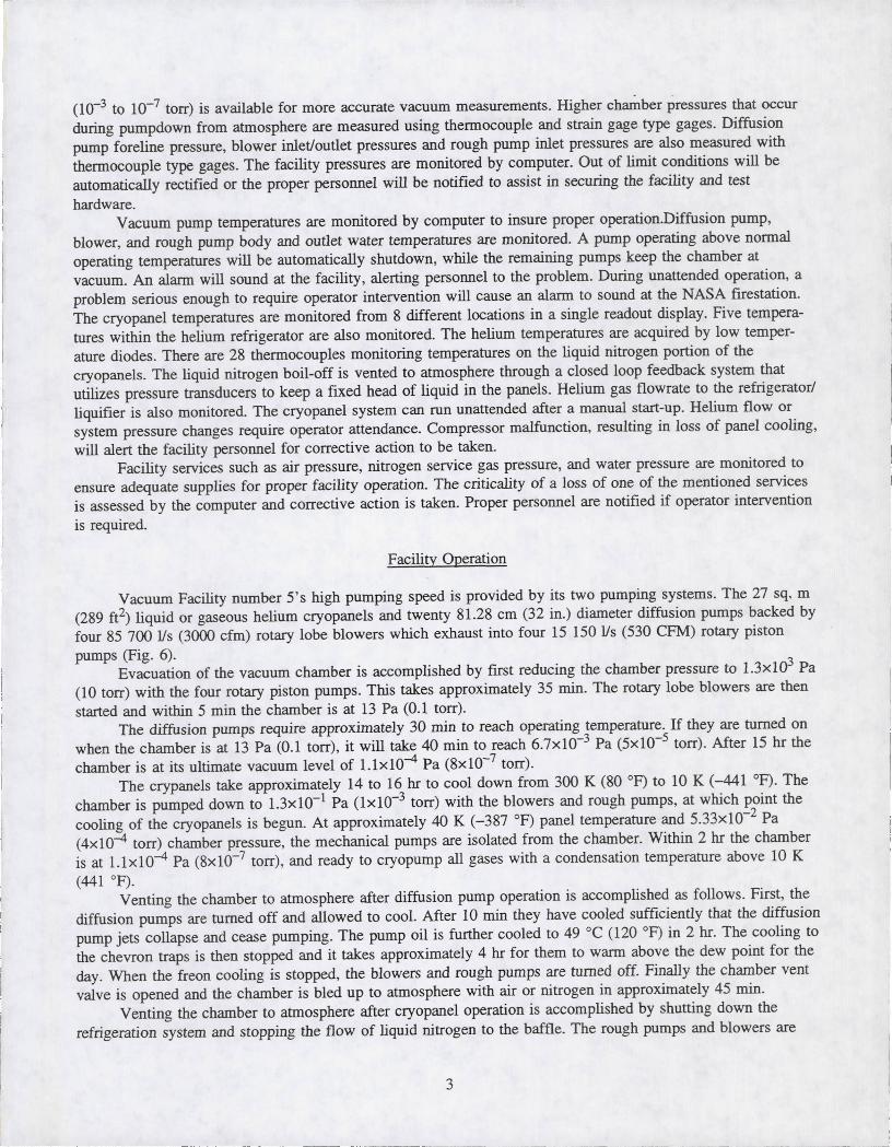
(10-3 to 10-7 torr) is available for more accurate vacuum measurements. Higher chamber pressures that occur during pumpdown from atmosphere are measured using thermocouple and strain gage type gages. Diffusion pump foreline pressure, blower inlet/outlet pressures and rough pump inlet pressures are also measured with thermocouple type gages. The facility pressures are monitored by computer. Out of limit conditions will be automatically rectified or the proper personnel will be notified to assist in securing the facility and test hardware.
Vacuum pump temperatures are monitored by computer to insure proper operation.Diffusion pump, blower, and rough pump body and outlet water temperatures are monitored. A pump operating above normal operating temperatures will be automatically shutdown, while the remaining pumps keep the chamber at vacuum. An alarm will sound at the facility, alerting personnel to the problem. During unattended operation, a problem serious enough to require operator intervention will cause an alarm to sound at the NASA firestation. The cryopanel temperatures are monitored from 8 different locations in a single readout display. Five temperatures within the helium refrigerator are also monitored. The helium temperatures are acquired by low temperature diodes. There are 28 thermocouples monitoring temperatures on the liquid nitrogen portion of the cryopanels. The liquid nitrogen boil-off is vented to atmosphere through a closed loop feedback system that utilizes pressure transducers to keep a fixed head of liquid in the panels. Helium gas flowrate to the refrigerator/ liquifier is also monitored. The cryopanel system can run unattended after a manual start-up. Helium flow or system pressure changes require operator attendance. Compressor malfunction, resulting in loss of panel cooling, will alert the facility personnel for corrective action to be taken.
Facility services such as air pressure, nitrogen service gas pressure, and water pressure are monitored to ensure adequate supplies for proper facility operation. The criticality of a loss of one of the mentioned services is assessed by the computer and corrective action is taken. Proper personnel are notified if operator intervention is required.
Facility Operation
Vacuum Facility number 5' s high pumping speed is provided by its two pumping systems. The 27 sq. m (289 ft2) liquid or gaseous helium cryopanels and twenty 81.28 cm (32 in.) diameter diffusion pumps backed by four 85 700 lis (3000 cfm) rotary lobe blowers which exhaust into four 15 150 lis (530 CFM) rotary piston pumps (Fig. 6).
Evacuation of the vacuum chamber is accomplished by first reducing the chamber pressure to 1.3x10³ Pa (10 torr) with the four rotary piston pumps. This takes approximately 35 min. The rotary lobe blowers are then started and within 5 min the chamber is at 13 Pa (0.1 torr).
The diffusion pumps require approximately 30 min to reach operating temperature. If they are turned on when the chamber is at 13 Pa (0.1 torr), it will take 40 min to reach 6.7xlO-3 Pa (5xlO-5 torr) . After 15 hr the chamber is at its ultimate vacuum level of 1. Ix 10-4 Pa (8xlO-7 torr).
The crypanels take approximately 14 to 16 hr to cool down from 300 K (80 OF) to 10 K (-441 OF). The chamber is pumped down to 1.3xlO-1 Pa (lxlO-3 torr) with the blowers and rough pumps, at which point the cooling of the cryopanels is begun. At approximately 40 K (-387 OF) panel temperature and 5.33xlO-2 Pa (4xlO-4 torr) chamber pressure, the mechanical pumps are isolated from the chamber. Within 2 hr the chamber is at 1.1xlO-4 Pa (8xlO-7 torr) , and ready to cryopump all gases with a condensation temperature above 10 K (441 °F).
Venting the chamber to atmosphere after diffusion pump operation is accomplished as follows. First, the diffusion pumps are turned off and allowed to cool. After 10 min they have cooled sufficiently that the diffusion pump jets collapse and cease pumping. The pump oil is further cooled to 49 °C (120 OF) in 2 hr. The cooling to the chevron traps is then stopped and it takes approximately 4 hr for them to warm above the dew point for the day. When the freon cooling is stopped, the blowers and rough pumps are turned off. Finally the chamber vent valve is opened and the chamber is bled up to atmosphere with air or nitrogen in approximately 45 min.
Venting the chamber to atmosphere after cryopanel operation is accomplished by shutting down the refrigeration system and stopping the flow of liquid nitrogen to the baffle. The rough pumps and blowers are
3
- -------I
L.
- --- ---~--~-
(10-3 to 10-7 torr) is available for more accurate vacuum measurements. Higher chamber pressures that occur during pumpdown from atmosphere are measured using thermocouple and strain gage type gages. Diffusion pump foreline pressure, blower inlet/outlet pressures and rough pump inlet pressures are also measured with thermocouple type gages. The facility pressures are monitored by computer. Out of limit conditions will be automatically rectified or the proper personnel will be notified to assist in securing the facility and test hardware.
Vacuum pump temperatures are monitored by computer to insure proper operation.Diffusion pump, blower, and rough pump body and outlet water temperatures are monitored. A pump operating above normal operating temperatures will be automatically shutdown, while the remaining pumps keep the chamber at vacuum. An alarm will sound at the facility, alerting personnel to the problem. During unattended operation, a problem serious enough to require operator intervention will cause an alarm to sound at the NASA firestation. The cryopanel temperatures are monitored from 8 different locations in a single readout display. Five temperatures within the helium refrigerator are also monitored. The helium temperatures are acquired by low temperature diodes. There are 28 thermocouples monitoring temperatures on the liquid nitrogen portion of the cryopanels. The liquid nitrogen boil-off is vented to atmosphere through a closed loop feedback system that utilizes pressure transducers to keep a fixed head of liquid in the panels. Helium gas flowrate to the refrigerator/ liquifier is also monitored. The cryopanel system can run unattended after a manual start-up. Helium flow or system pressure changes require operator attendance. Compressor malfunction, resulting in loss of panel cooling, will alert the facility personnel for corrective action to be taken.
Facility services such as air pressure, nitrogen service gas pressure, and water pressure are monitored to ensure adequate supplies for proper facility operation. The criticality of a loss of one of the mentioned services is assessed by the computer and corrective action is taken. Proper personnel are notified if operator intervention is required.
Facility Operation
Vacuum Facility number 5' s high pumping speed is provided by its two pumping systems. The 27 sq. m (289 ft2) liquid or gaseous helium cryopanels and twenty 81.28 cm (32 in.) diameter diffusion pumps backed by four 85 700 lis (3000 cfm) rotary lobe blowers which exhaust into four 15 150 lis (530 CFM) rotary piston pumps (Fig. 6).
Evacuation of the vacuum chamber is accomplished by first reducing the chamber pressure to 1.3x10³ Pa (10 torr) with the four rotary piston pumps. This takes approximately 35 min. The rotary lobe blowers are then started and within 5 min the chamber is at 13 Pa (0.1 torr).
The diffusion pumps require approximately 30 min to reach operating temperature. If they are turned on when the chamber is at 13 Pa (0.1 torr), it will take 40 min to reach 6.7xlO-3 Pa (5xlO-5 torr) . After 15 hr the chamber is at its ultimate vacuum level of 1. Ix 10-4 Pa (8xlO-7 torr).
The crypanels take approximately 14 to 16 hr to cool down from 300 K (80 OF) to 10 K (-441 OF). The chamber is pumped down to 1.3xlO-1 Pa (lxlO-3 torr) with the blowers and rough pumps, at which point the cooling of the cryopanels is begun. At approximately 40 K (-387 OF) panel temperature and 5.33xlO-2 Pa (4xlO-4 torr) chamber pressure, the mechanical pumps are isolated from the chamber. Within 2 hr the chamber is at 1.1xlO-4 Pa (8xlO-7 torr) , and ready to cryopump all gases with a condensation temperature above 10 K (441 °F).
Venting the chamber to atmosphere after diffusion pump operation is accomplished as follows. First, the diffusion pumps are turned off and allowed to cool. After 10 min they have cooled sufficiently that the diffusion pump jets collapse and cease pumping. The pump oil is further cooled to 49 °C (120 OF) in 2 hr. The cooling to the chevron traps is then stopped and it takes approximately 4 hr for them to warm above the dew point for the day. When the freon cooling is stopped, the blowers and rough pumps are turned off. Finally the chamber vent valve is opened and the chamber is bled up to atmosphere with air or nitrogen in approximately 45 min.
Venting the chamber to atmosphere after cryopanel operation is accomplished by shutting down the refrigeration system and stopping the flow of liquid nitrogen to the baffle. The rough pumps and blowers are
3
- -------
I
then operated to remove the gases from the chamber as they vaporize from the panels. After the cryopanels warm to a temperature above the dew point (15 hr), the rough pumps and blowers can be isolated from the chamber. The chamber can then be vented to atmosphere.
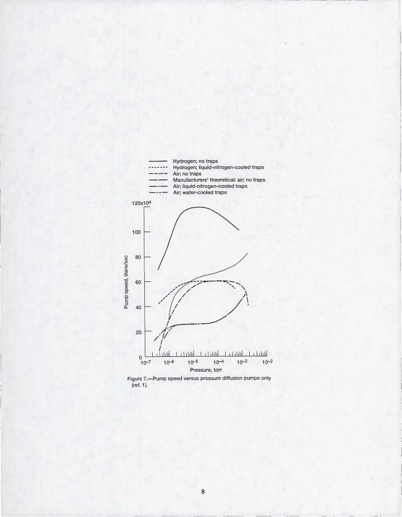
The diffusion pumped pumping speed of Vacuum Facility number 5 has been detennined for various configurations as shown in IJf. 7 and Ref. 1. The maximum pumping speed for air is 250 000 lfs at 1.33xlO-2
to 1.33xlO-4 Pa (10-4 to 10 torr), and for hydrogen it is 660 000 lfs at 1.33xl0-2 Pa (10-4 torr). The cryopumped pumping speed of the chamber has been detennined for Argon and Xenon. The
maximum pumping s~eed for Argon is 300 000 lfs at 1.33xlO-2 Pa (10-4 torr), and for Xenon it is 150000 lfs at 1.33xlO-3 Pa (10- torr). Total facility pumping speeds in excess of 450000 lfs for Argon is possible using both pumping systems simultaneously.
References
1. Finke, R.e.; Holmes, A.D.; Keller, T.A.: Space Environment Facility For electric Propulsion Systems Research. NASA TN D-2774, May 1965.
4
l ___ _ I
then operated to remove the gases from the chamber as they vaporize from the panels. After the cryopanels warm to a temperature above the dew point (15 hr), the rough pumps and blowers can be isolated from the chamber. The chamber can then be vented to atmosphere.
The diffusion pumped pumping speed of Vacuum Facility number 5 has been detennined for various configurations as shown in IJf. 7 and Ref. 1. The maximum pumping speed for air is 250 000 lfs at 1.33xlO-2
to 1.33xlO-4 Pa (10-4 to 10 torr), and for hydrogen it is 660 000 lfs at 1.33xl0-2 Pa (10-4 torr). The cryopumped pumping speed of the chamber has been detennined for Argon and Xenon. The
maximum pumping s~eed for Argon is 300 000 lfs at 1.33xlO-2 Pa (10-4 torr), and for Xenon it is 150000 lfs at 1.33xlO-3 Pa (10- torr). Total facility pumping speeds in excess of 450000 lfs for Argon is possible using both pumping systems simultaneously.
References
1. Finke, R.e.; Holmes, A.D.; Keller, T.A.: Space Environment Facility For electric Propulsion Systems Research. NASA TN D-2774, May 1965.
4
l ___ _
\" Freon system \ compressors
\
/
/ 56 000 gai i..N 2 :)ewar
/
Vacuum 1acl •• ty ::3 \
\\l acuum facility;;5 \~
roots blowers .,j
\ \
Figure 1.-Electric Power Laboratory; 15t floor.
Figure 2.-Electric Power Laboratory; 2nd floor.
5
acuum faCIlity it5
fOUgh'ng pumps
\" G"'e storage
\
C-90..Q8357
\" Freon system \ compressors
\
/
/ 56 000 gai i..N 2 :)ewar
/
Vacuum 1acl •• ty ::3 \
\\l acuum facility;;5 \~
roots blowers .,j
\ \
Figure 1.-Electric Power Laboratory; 15t floor.
Figure 2.-Electric Power Laboratory; 2nd floor.
5
acuum faCIlity it5
fOUgh'ng pumps
\" G"'e storage
\
C-90..Q8357
Figure 3.-Vacuum facility #5; moveable end cap.
Figure 4.-Test hardware and moveable cart.
6
--~ .... ----------
Figure 3.-Vacuum facility #5; moveable end cap.
Figure 4.-Test hardware and moveable cart.
6
--~ .... ----------
Moveable end cap -.
r./
/ I
I I I 1 1 1 1 \ \ \ \ , ,
'4-
Midtank shield """"'\
\ \ \
\ \ \
\ \
Test compartment with vacuum gate valve
Figure 5.-Vacuum facility #5 (15 ft diam x 63 ft overall).
, r-1J\,""","-----' ,
, "
-I', : ~ __ ..-- Oil
:-- \{ diffusion 1 / , pumps 1 / 1 1 / I (30 000 US) Y 1
/ 1 1 I 1 I I
: ,/ 1/
'- Rotary lobe blowers (3000 CFM)
>- Rotary '-JI.I ..... -r--, / piston pumps
(530 CFM)
Figure 6.-Vacuum facility #5; vacuum piping.
7
I ,
I
1-
(,) Q)
..!(! ~
~ -0 Q) Q) c. (f)
c. E :J 0..
-- --- _._---- - --
120x104
100
80
60
40
20
o 10'-7
Hydrogen; no traps Hydrogen; liquid-nitrogen-cooled traps Air; no traps Manufacturers' theoretical : air; no traps Air; liquid-nitrogen-cooled traps Air; water-cooled traps
Pressure, torr
Figure 7.-Pump speed versus pressure diffusion pumps only (ref. 1).
8
.-~
REPORT DOCUMENTATION PAGE Form Approved
OMB No. 0704-0188 Public reporting burden for th is collection of information is estimated to average 1 hour per response, including the time for reviewing instructions, searching existing data sources, gathering and maintaining the data needed. and completing and reviewing the collection of information. Send comments regarding this burden estimate or any other aspect of this collection of information, including suggestions for reducing this burden, to Washington Headquarters Services, Directorate for Information-Operations and Reports, 1215 Jefferson Davis Highway, Suite 1204, Arlington, VA 22202-4302, and to the Office of Management and Budget, Paperwor1< Reduction Project (0704-0188), Washington, DC 20503.
1. AGENCY USE ONLY (Leave blank) \2. REPORT DATE r- REPORT TYPE AND DATES COVERED
January 1994 Technical Memorandum 4. TITLE AND SUBTITLE 5. FUNDING NUMBERS
A Large High Vacuum, High Pumping Speed Space Simulation Chamber for Electric Propulsion
6. AUTHOR(S) WU-506-42-31
Stanley P. Grisnik and James E. Parkes
7. PERFORMING ORGANIZATION NAME(S) AND ADDRESS(ES) 8. PERFORMING ORGANIZATION REPORT NUMBER
National Aeronautics and Space Administration Lewis Research Center E-8080 Cleveland, Ohio 44135-3191
9. SPONSORINGIMONITORING AGENCY NAME(S) AND ADDRESS(ES) 10. SPONSORINGIMONITORING AGENCY REPORT NUMBER
National Aeronautics and Space Administration NASA TM-106453
Washington, D.C. 20546-0001 IEPC-93-151
11 _ SUPPLEMENTARY NOTES Prepared for the 23rd International Electric Propulsion Conference cosponsored by the AIAA, AIDAA, DGLR, and lSASS, Seattle, Washington, September 13-16, 1993. Stanley P. Grisnik, NASA Lewis Research Center, and James E. Parkes, Sverdrup Technology, Inc., Lewis Research Center Group, 2001 Aerospace Parkway, Brook Park, Ohio 44142 (work funded by NASA Contract NAS3-2S266). Responsible person, Stanley P. Grisnik, (216) 433-7441.
12a. DISTRIBUTION/AVAILABILITY STATEMENT 12b_ DISTRIBUTION CODE
Unclassified - Unlimited Subject Category 14
13. ABSTRACT (Maximum 200 words)
Testing high power electric propulsion devices poses unique requirements on space simulation facilities_ Very high pumping speeds are required to maintain high vacuum levels while handling large volumes of exhaust products. These pumping speeds are significantly higher than those available in most existing vacuum facilities. There is also a require-ment for relatively large vacuum chamber dimensions to minimize facility wall/thruster plume interactions and to accommodate far field plume diagnostic measurements. A 4.57 m (15 ft) diameter by 19.2 m (63 ft) long vacuum chamber at NASA Lewis Research Center is described in this paper. The chamber utilizes oil diffusion pumps in combination with cryopanels to achieve high vacuum pumping speeds at high vacuum levels. The facility is computer controlled for all phases of operation from start-up, through testing, to shutdown. The computer control system increases the utilization of the facility and reduces the manpower requirements needed for facility operations.
14. SUBJECT TERMS 15. NUMBER OF PAGES
10 Space simulation chamber; Electric propulsion; Vacuum chamber 16. PRICE CODE
NSN 7540-01-280-5500 Standard Form 298 (Rev. 2-89) Prescribed by ANSI Std. Z39-18 298-102
l I
REPORT DOCUMENTATION PAGE Form Approved
OMB No. 0704-0188 Public reporting burden for th is collection of information is estimated to average 1 hour per response, including the time for reviewing instructions, searching existing data sources, gathering and maintaining the data needed. and completing and reviewing the collection of information. Send comments regarding this burden estimate or any other aspect of this collection of information, including suggestions for reducing this burden, to Washington Headquarters Services, Directorate for Information-Operations and Reports, 1215 Jefferson Davis Highway, Suite 1204, Arlington, VA 22202-4302, and to the Office of Management and Budget, Paperwor1< Reduction Project (0704-0188), Washington, DC 20503.
1. AGENCY USE ONLY (Leave blank) \2. REPORT DATE r- REPORT TYPE AND DATES COVERED
January 1994 Technical Memorandum 4. TITLE AND SUBTITLE 5. FUNDING NUMBERS
A Large High Vacuum, High Pumping Speed Space Simulation Chamber for Electric Propulsion
6. AUTHOR(S) WU-506-42-31
Stanley P. Grisnik and James E. Parkes
7. PERFORMING ORGANIZATION NAME(S) AND ADDRESS(ES) 8. PERFORMING ORGANIZATION REPORT NUMBER
National Aeronautics and Space Administration Lewis Research Center E-8080 Cleveland, Ohio 44135-3191
9. SPONSORINGIMONITORING AGENCY NAME(S) AND ADDRESS(ES) 10. SPONSORINGIMONITORING AGENCY REPORT NUMBER
National Aeronautics and Space Administration NASA TM-106453
Washington, D.C. 20546-0001 IEPC-93-151
11 _ SUPPLEMENTARY NOTES Prepared for the 23rd International Electric Propulsion Conference cosponsored by the AIAA, AIDAA, DGLR, and lSASS, Seattle, Washington, September 13-16, 1993. Stanley P. Grisnik, NASA Lewis Research Center, and James E. Parkes, Sverdrup Technology, Inc., Lewis Research Center Group, 2001 Aerospace Parkway, Brook Park, Ohio 44142 (work funded by NASA Contract NAS3-2S266). Responsible person, Stanley P. Grisnik, (216) 433-7441.
12a. DISTRIBUTION/AVAILABILITY STATEMENT 12b_ DISTRIBUTION CODE
Unclassified - Unlimited Subject Category 14
13. ABSTRACT (Maximum 200 words)
Testing high power electric propulsion devices poses unique requirements on space simulation facilities_ Very high pumping speeds are required to maintain high vacuum levels while handling large volumes of exhaust products. These pumping speeds are significantly higher than those available in most existing vacuum facilities. There is also a require-ment for relatively large vacuum chamber dimensions to minimize facility wall/thruster plume interactions and to accommodate far field plume diagnostic measurements. A 4.57 m (15 ft) diameter by 19.2 m (63 ft) long vacuum chamber at NASA Lewis Research Center is described in this paper. The chamber utilizes oil diffusion pumps in combination with cryopanels to achieve high vacuum pumping speeds at high vacuum levels. The facility is computer controlled for all phases of operation from start-up, through testing, to shutdown. The computer control system increases the utilization of the facility and reduces the manpower requirements needed for facility operations.
14. SUBJECT TERMS 15. NUMBER OF PAGES
10 Space simulation chamber; Electric propulsion; Vacuum chamber 16. PRICE CODE