ACTA GEOTECHNICA SLOVENICA, 2012/1 61. MURAT ORNEK, AHMET DEMIR, MUSTAFA LAMAN and ABDULAZIM YILDIZ NUMERICAL ANALYSIS OF CIRCULAR FOOTINGS ON NATURAL CLAY STABILIZED WITH A GRANULAR FILL about the authors Murat Ornek Mustafa Kemal University, Civil Engineering Department Iskenderun/Hatay, Turkey E-mail: [email protected]Ahmet Demir Korkut Ata University, Civil Engineering Department 80000 Osmaniye, Turkey E-mail: [email protected]Abdulazim Yildiz Cukurova University, Civil Engineering Department 01330 Balcali/Adana, Turkey E-mail: [email protected]corresponding author Mustafa Laman Cukurova University, Civil Engineering Department 01330 Balcali/Adana, Turkey E-mail: [email protected]Abstract In this study, numerical predictions of the scale effect for circular footings supported by partially replaced, compacted, layers on natural clay deposits are presented. e scale- effect phenomenon was analyzed according to the footing sizes. Numerical analyses were carried out using an axisym- metric, two-dimensional, finite-element program. Before conducting the analysis, the validity of the constitutive model was validated using field tests performed by authors with seven different footing diameters up to 0.90 m and with three different partial replacement thicknesses. It is shown that the behavior of the circular footings on natural clay soil and the partial replacement system can be reasonably well represented by the Mohr Coulomb model. e Mohr- Coulomb model parameters were derived from the results of conventional laboratory and field tests. Aſter achieving a good consistency between the results of the test and the numerical analysis, the numerical analyses were continued by increasing the footing diameter up to 25 m, considering the partial replacement thickness up to two times the footing diameter. e results of this parametric study showed that the stabilization had a considerable effect on the bearing capacity of the circular footings and for a given value of H/D the magnitude of the ultimate bearing capacity increases in a nonlinear manner with the footing diameter. e Bearing Capacity Ratio (BCR) was defined to evaluate the improved performance of the reinforced system. It was found, based on numerical and field-test results that the BCR of the partially replaced, natural clay deposits increased with an increase in the footing diameter and there was no significant scale effect of the circular footing resting on natural clay deposits. Keywords scale effect, circular footing, field test, finite-element analysis, natural clay, granular fill 1 INTRODUCTION e bearing capacity of shallow footings has been studied since Terzaghi’s original observation during the 1940s. Although additional considerations to the govern- ing criteria of bearing capacity have been proposed, the ultimate bearing-capacity calculation of a footing has changed very little since Terzaghi’s [1] first general equa- tion for the ultimate bearing capacity, q ult . e classic bearing-capacity formulation cannot be used directly in large-scaled footing design without a correlation. Small-scale, laboratory-model tests are easier to operate due to their small sizes and the cost is significantly less than large and full-scale in-situ tests. Because of these advantages, small-scale laboratory tests are preferable for studying the behavior of soil. However, it is difficult to simulate a soil’s characteristics (water content, density, strength etc.), exactly, especially in cohesive soils. Despite their operational and financial disadvantages, large and full-scale in-situ tests give more reasonable
Transcript
ACTA GEOTECHNICA SLOVENICA, 2012/1 61.
MURAT ORNEK, AHMET DEMIR, MUSTAFA LAMAN and ABDULAZIM YILDIZ
NUMERICAL ANALYSIS OF CIRCULAR FOOTINGS ON NATURAL CLAY STABILIZED WITH A GRANULAR FILL
about the authors
Murat OrnekMustafa Kemal University,Civil Engineering DepartmentIskenderun/Hatay, TurkeyE-mail: [email protected]
Ahmet DemirKorkut Ata University,Civil Engineering Department80000 Osmaniye, TurkeyE-mail: [email protected]
In this study, numerical predictions of the scale effect for circular footings supported by partially replaced, compacted, layers on natural clay deposits are presented. The scale- effect phenomenon was analyzed according to the footing sizes. Numerical analyses were carried out using an axisym-metric, two-dimensional, finite-element program. Before conducting the analysis, the validity of the constitutive model was validated using field tests performed by authors with seven different footing diameters up to 0.90 m and with three different partial replacement thicknesses. It is shown that the behavior of the circular footings on natural clay soil and the partial replacement system can be reasonably well represented by the Mohr Coulomb model. The Mohr-Coulomb model parameters were derived from the results of conventional laboratory and field tests. After achieving a good consistency between the results of the test and the
numerical analysis, the numerical analyses were continued by increasing the footing diameter up to 25 m, considering the partial replacement thickness up to two times the footing diameter. The results of this parametric study showed that the stabilization had a considerable effect on the bearing capacity of the circular footings and for a given value of H/D the magnitude of the ultimate bearing capacity increases in a nonlinear manner with the footing diameter. The Bearing Capacity Ratio (BCR) was defined to evaluate the improved performance of the reinforced system. It was found, based on numerical and field-test results that the BCR of the partially replaced, natural clay deposits increased with an increase in the footing diameter and there was no significant scale effect of the circular footing resting on natural clay deposits.
Keywords
scale effect, circular footing, field test, finite-element analysis, natural clay, granular fill
1 INTRODUCTION
The bearing capacity of shallow footings has been studied since Terzaghi’s original observation during the 1940s. Although additional considerations to the govern-ing criteria of bearing capacity have been proposed, the ultimate bearing-capacity calculation of a footing has changed very little since Terzaghi’s [1] first general equa-tion for the ultimate bearing capacity, qult. The classic bearing-capacity formulation cannot be used directly in large-scaled footing design without a correlation.
Small-scale, laboratory-model tests are easier to operate due to their small sizes and the cost is significantly less than large and full-scale in-situ tests. Because of these advantages, small-scale laboratory tests are preferable for studying the behavior of soil. However, it is difficult to simulate a soil’s characteristics (water content, density, strength etc.), exactly, especially in cohesive soils. Despite their operational and financial disadvantages, large and full-scale in-situ tests give more reasonable
ACTA GEOTECHNICA SLOVENICA, 2012/162.
results in when simulating soil behavior. It is known from the literature that most of the experimental studies on soils have been conducted using small-scale labora-tory tests and formulations have been derived from small-scale model footing tests. Small-scale model foot-ing tests produce higher values for the bearing capacities than those of theoretical equations and therefore they should not be used for the design of full-scale footings without a reduction [2, 3].
The difference in performance between the actual large and/or full scaled soil footings and the model footing tests should be considered. The relationship between the tests with small- and large-scaled footing is known as the “scale effect” in geotechnical engineering. This relation validated by theoretical, analytical and numerical analy-ses gives advantages in geotechnical design. An effective, suitable scale-effect investigation or, in other words, a proper scale-effect ratio helps to decrease the design expenses, gain time for design procedures and get simpler operational processes. Siddiquee et al. [4] reported that the scale effect is the variation in the bearing capacity characteristics with the variation in the footing size.
The literature review is divided into the “scale-effect” and the “reinforcement of weak soils” in this study. There are limited studies focused directly on a “scale-effect” investigation in the literature [5-10]. Berry [5] was an early reporter of the scale-effect phenomenon and showed that the bearing capacity of circular footings decreases with the increasing footing size on dense sand at a constant relative density. This means that the bear-ing capacity factor, Nγ decreases with increasing footing size, when Nγ was obtained from a back-calculation. Fukushima et al. [11] identified appropriate design constants to take into account scale effects. They investi-gated the scale-effect properties of the ultimate bearing capacity that accompanies the changes in the shape of the spread footing by conducting the plate-loading test on soft-rock ground, gravelly soil and rock-fill embank-ment, where the dimensional shape of the loading plates are changed. They concluded that plate loading tests in which the loading-plate scale is changed, are practical as an investigation method for design constants to take into consideration the scale effects in spread-footing design. Cerato and Lutenegger [2] concluded that the scale effect occurs because of the stress dependency of sand soils and they described it as “different sized footings have different mean stresses; the smaller the footing is the smaller the mean stresses”.
A shortage of the availability of proper construction sites in city centers has led to the increased use of problematic areas where the bearing capacity of the underlying deposits is very low. The partial replacement of these
problematic soils with a layer is one of the soil-improve-ment techniques that is widely used. Problematic soil behavior can be improved by totally or partially replac-ing inadequate soils with compacted in layers. Several experimental and numerical studies have been described about the reinforcement of a weak soft soil [12-19]. Adams and Collin [2] conducted 34 large model load tests to evaluate the potential benefits of geosynthetic-reinforced spread foundations. It was concluded that the soil–geosynthetic system formed a composite material that inhibited the development of the soil-failure wedge beneath the shallow spread foundations. Alawaji [13] discussed the effects of reinforcing the sand pad over collapsible soil and reported that a successive reduction in the collapse settlement up to 75% was obtained. Dash et al. [14] performed model tests in the laboratory to study the response of the reinforcing granular fill overly-ing soft clay beds and showed that substantial improve-ments in the load-carrying capacity and a reduction in surface heaving of the foundation bed were obtained.
This study is focused directly on the scale-effect investi-gation in circular footings rested on natural clay deposits stabilized with compacted granular-fill layers. Numeri-cal analyses were carried out using two-dimensional, finite-element formulations. Before conducting the analysis, the validity of the constitutive model was proved using field tests performed by the authors, with seven different footing diameters up to 0.90 m and three different compacted granular-fill layer thicknesses. After achieving a good consistency, the numerical analyses were continued by increasing the footing diameter up to 25 m. In this parametric study, the granular-fill layer thicknesses were selected as 0.17D; 0.33D; 0.67D; 1.00D; 1.33D; 1.67D and 2.00D according to the foot-ing diameter. The results of this study showed that the partial replacement with compacted granular-fill layer had a considerable effect on the bearing capacity of the circular footings. It was found based on the numerical and field test results that the Bearing Capacity Ratio (BCR) of the stabilized natural clay deposits increased with an increase in the footing diameter and there was no significant scale effect of circular footing resting on natural clay deposits.
2 FIELD TESTS
2.1 SITE CHARACTERIZATION
A total of 28 field tests were conducted at the Adana Metropolitan Municipality’s (AMM) Water Treatment Facility Center (WTFC) located in west part of Adana, Turkey. The soil conditions at the experimental test
M. ORNEK ET AL.: NUMERICAL ANALYSIS OF CIRCULAR FOOTINGS ON NATURAL CLAY STABILIZED WITH A GRANULAR FILL
ACTA GEOTECHNICA SLOVENICA, 2012/1 63.
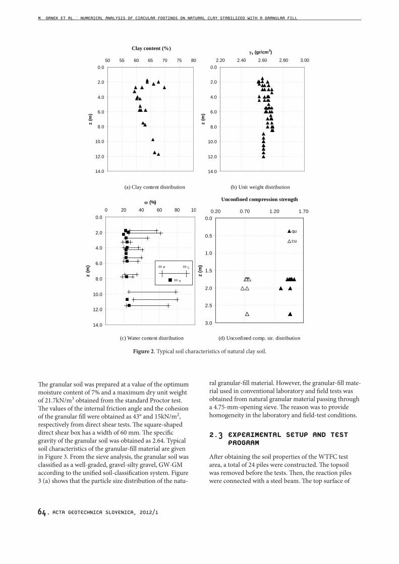
site (WTFC) were determined from a geotechnical site investigation comprised of both field and laboratory tests. Two test- pit excavations (TP1 and TP2) and four borehole drillings (BH1, BH2, BH3 and BH4) were performed in the WTFC test area. The test area has dimensions of 30m (length) by 11.6m (width). The test pits were excavated to a depth of 2.50 m and boreholes were drilled with diameters of 10cm and depths of 13m. The borehole drilled in the south side was 20 m deep. The ground-water level was observed to be 2.2m, from the borehole drillings. The field tests were conducted at a depth of about 2.0m from the ground surface. The degree of saturation ratio was measured to be around 80% at this level. Three subsoil layers were clearly identified by visual inspection and by a unified soil-classification system. The first layer, with a depth of 0.80 m, observed as topsoil, was removed before the tests. The intermediate layer between the depths of 0.80 m and 7.0 m exhibits a silty clay stratum with high plasticity (CH). A silty clay layer with the intrusion of sand (CL) was observed in the bottom layer up to 10.0 m depth. A Standard Penetration Test (SPT) was carried out during the drilling of each borehole and the soil tested was classified as medium stiff clay. The distribution of the SPT values with depth, including the soil profile, is shown in Figure 1. Conventional laboratory tests, such as a sieve analysis, moisture content, Atterberg limit, specific gravity, standard Proctor, unconfined compression, laboratory vane, triaxial and consolidation tests, were performed in the Geotechnical Laboratory of Civil Engineering Department at Cukurova University, Adana, Turkey. The clay content of the soil layers varies
in the range between 60 and 70%. The upper homo-geneous layer where all the loading tests were carried out is classified as a high plasticity clay (CH) according to the Unified Soil Classification System (USCS). The water content of the stratified soil layers varies between 20 and 25% depending on the depth, and is almost the same as, or greater than, the plastic limit. The specific gravities (Gs) vary from 2.60 to 2.65 along the depths. The triaxial, consolidation and unconfined compres-sion tests were conducted on undisturbed soil samples derived from the field. The values of the undrained shear strengths, cu were determined by unconfined compres-sion tests in the range 60 to 80 kN/m2. The values of the undrained shear strengths cu from the unconsolidated undrained, triaxial test were obtained as 70-80 kN/m2. The clay soil layer can generally be classified as a lightly overconsolidated clay based on odometer test results. The typical soil characteristics of the natural clay soil are given in Figure 2.
2.2 DETAILS OF THE MODEL FOOTINGS AND GRANULAR-FILL MATERIAL USED
Seven different footings with diameters of 0.06, 0.09, 0.12, 0.30, 0.45, 0.60 and 0.90 m were used in this study. These rigid, steel-made footings have a thickness of 2cm for D ≤ 12 cm and 3 cm for D > 12 cm, where D is the footing diameter. The granular-fill material used in the model tests was obtained from the Kabasakal region situated northwest of Adana, Turkey. Some conventional tests (sieve analysis, moisture content, unit weight, direct shear and proctor tests) were conducted on this material.
Figure 1. SPT(N) values measured from the boreholes.
M. ORNEK ET AL.: NUMERICAL ANALYSIS OF CIRCULAR FOOTINGS ON NATURAL CLAY STABILIZED WITH A GRANULAR FILL
ACTA GEOTECHNICA SLOVENICA, 2012/164.
0.0
2.0
4.0
6.0
8.0
10.0
12.0
14.0
50 55 60 65 70 75 80Kil Yüzdesi (%)
z (m
)
0.0
2.0
4.0
6.0
8.0
10.0
12.0
14.0
2.20 2.40 2.60 2.80 3.00
s (gr/cm3)
z (m
)
Clay content (%)
(b) Unit weight distribution (a) Clay content distribution
0.0
2.0
4.0
6.0
8.0
10.0
12.0
14.0
0 20 40 60 80 100 (%)
z (m
) LP
n
0.0
0.5
1.0
1.5
2.0
2.5
3.0
0.20 0.70 1.20 1.70Serbest Basınç Mukavemeti
z (m
)
qu
cu
Unconfined compression strength
(d) Unconfined comp. str. distribution (c) Water content distribution
Figure 2. Typical soil characteristics of natural clay soil.
The granular soil was prepared at a value of the optimum moisture content of 7% and a maximum dry unit weight of 21.7kN/m3 obtained from the standard Proctor test. The values of the internal friction angle and the cohesion of the granular fill were obtained as 43° and 15kN/m2, respectively from direct shear tests. The square-shaped direct shear box has a width of 60 mm. The specific gravity of the granular soil was obtained as 2.64. Typical soil characteristics of the granular-fill material are given in Figure 3. From the sieve analysis, the granular soil was classified as a well-graded, gravel-silty gravel, GW-GM according to the unified soil-classification system. Figure 3 (a) shows that the particle size distribution of the natu-
ral granular-fill material. However, the granular-fill mate-rial used in conventional laboratory and field tests was obtained from natural granular material passing through a 4.75-mm-opening sieve. The reason was to provide homogeneity in the laboratory and field-test conditions.
2.3 EXPERIMENTAL SETUP AND TEST PROGRAM
After obtaining the soil properties of the WTFC test area, a total of 24 piles were constructed. The topsoil was removed before the tests. Then, the reaction piles were connected with a steel beam. The top surface of
M. ORNEK ET AL.: NUMERICAL ANALYSIS OF CIRCULAR FOOTINGS ON NATURAL CLAY STABILIZED WITH A GRANULAR FILL
ACTA GEOTECHNICA SLOVENICA, 2012/1 65.
Figure 3. Typical soil characteristics of granular-fill material.
the test area was leveled and the footing was placed on a predefined alignment such that the loads from the hydraulic jack and the loading frame would be transferred concentrically to the footing. A hydraulic jack against the steel beam provided the downward load. The hydraulic jack and two linear variable displace-ment transducers (LVDTs) were connected to a data logger unit and the data logger unit was connected to a computer. The granular-fill material was placed and compacted in layers. The thickness of each layer was changed depending on the footing diameter. The amount of granular-fill material and water needed for each layer was first calculated. Then, the granular-fill material was compacted using a plate compactor to a predetermined height to achieve the desired densities. The compacted,
granular-fill layer has a moisture content of 7% and a unit weight of 20.2 kN/m3. Load was applied with a hydraulic jack and maintained manually with a hand pump. The load and the corresponding footing settle-ment were measured with a calibrated pressure gauge and two LVDTs, respectively. The testing procedure was performed according to the ASTM D 1196-93 [20], where the load increments applied and maintained until the rate of settlement were less than 0.03 mm/min over three consecutive minutes. To maintain the same density throughout the test area, a convenient compactive effort was applied to each layer of the granular fill. Some tests were repeated twice to verify the repeatability and the consistency of the test data. The same pattern of the load-settlement relationship with a difference of the
Figure 4. Schematic view of test setup, loading, reaction system and typical layout of the instrumentation.
M. ORNEK ET AL.: NUMERICAL ANALYSIS OF CIRCULAR FOOTINGS ON NATURAL CLAY STABILIZED WITH A GRANULAR FILL
w (%)
γ d
ACTA GEOTECHNICA SLOVENICA, 2012/166.
ultimate load values less than 2.0% was obtained. This difference was considered to be small and neglected. The tests were continued until the applied vertical load was clearly reduced or a considerable settlement of the footing was obtained from a relatively small increase of the vertical load. Detailed information about the testing procedure can be found in Laman et al. [21] and Ornek [22]. The general layout of the test setup is given in Figure 4.
The research was conducted in two series. Series I consisted of the testing of seven different footing diameters (0.06, 0.09, 0.12, 0.30, 0.45, 0.60 and 0.90 m) on the surface of a natural clay deposit. Series II was the same as Series I, except that the footings were placed on a granular-fill layer settled on a natural clay deposit. The granular-fill layers were designed in three different thicknesses according to the footing diameters (0.33D; 0.67D and 1.00D).
3 FINITE-ELEMENT ANALYSIS
Numerical analysis is a powerful mathematical tool that makes it possible to solve complex engineering prob-lems. The finite-element method is a well-established numerical analysis technique used widely in many civil engineering applications, both for research and the design of real engineering problems. The constitutive behavior of soils can be successfully modeled with numerical analyses. The finite-element method is one of the mathematical methods in which continuous media is divided into finite elements with different geometries. It provides the advantage of idealizing the material behav-ior of the soil, which is non-linear with plastic deforma-tions and is stress-path dependent, in a more rational manner. The finite-element method can also be particu-larly useful for identifying the patterns of deformations and stress distribution during deformation and at the ultimate state. Because of these capabilities of the finite-element method, it is possible to model the construction method and investigate the behavior of shallow footings and the surrounding soil throughout the construction process, not just at the limit equilibrium conditions [23].
Numerical analyses were conducted using the program Plaxis 2D V8.6. It is a finite-element package that is specially developed for the analysis of deformation and stability in geotechnical engineering problems [24]. The stresses, strains and failure states of a given problem can be calculated.
Plaxis incorporates a fully automatic, mesh-generation procedure, in which the geometry is divided into
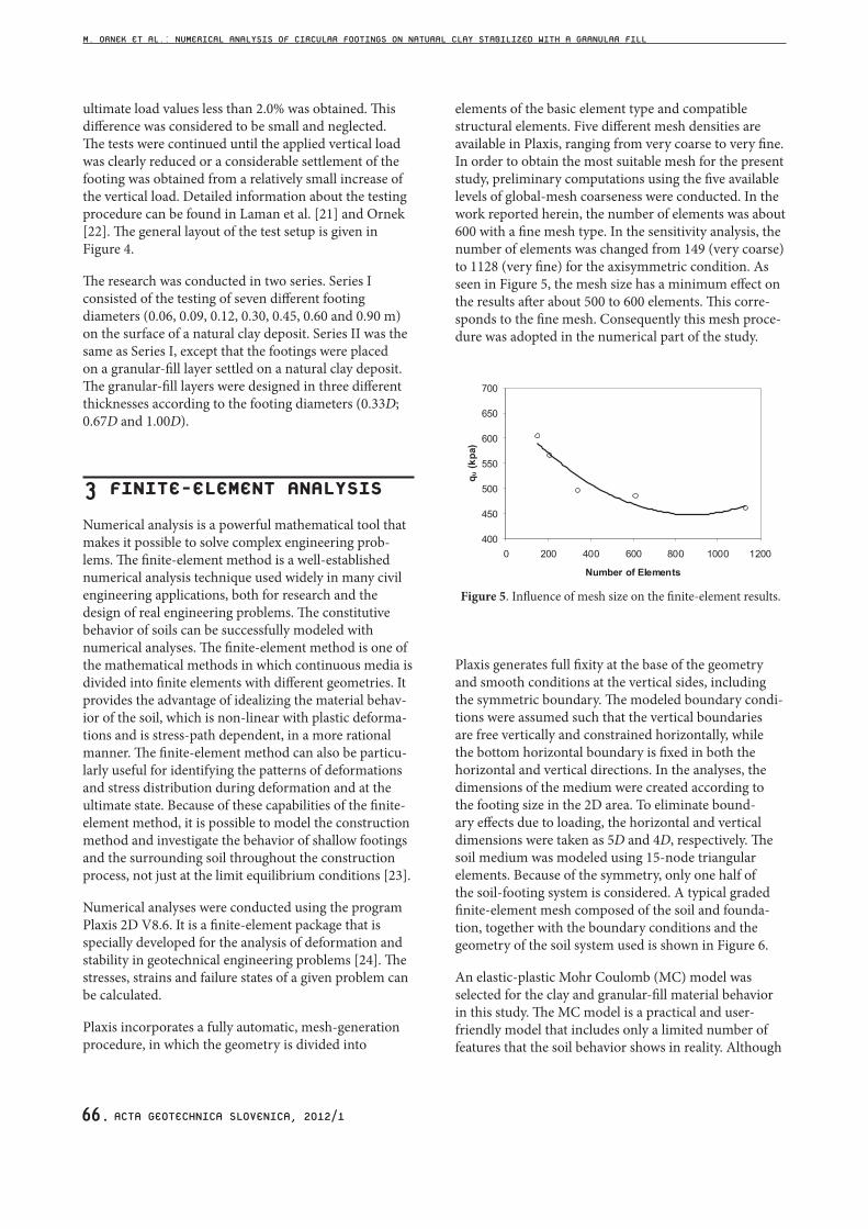
elements of the basic element type and compatible structural elements. Five different mesh densities are available in Plaxis, ranging from very coarse to very fine. In order to obtain the most suitable mesh for the present study, preliminary computations using the five available levels of global-mesh coarseness were conducted. In the work reported herein, the number of elements was about 600 with a fine mesh type. In the sensitivity analysis, the number of elements was changed from 149 (very coarse) to 1128 (very fine) for the axisymmetric condition. As seen in Figure 5, the mesh size has a minimum effect on the results after about 500 to 600 elements. This corre-sponds to the fine mesh. Consequently this mesh proce-dure was adopted in the numerical part of the study.
Figure 5. Influence of mesh size on the finite-element results.
Plaxis generates full fixity at the base of the geometry and smooth conditions at the vertical sides, including the symmetric boundary. The modeled boundary condi-tions were assumed such that the vertical boundaries are free vertically and constrained horizontally, while the bottom horizontal boundary is fixed in both the horizontal and vertical directions. In the analyses, the dimensions of the medium were created according to the footing size in the 2D area. To eliminate bound-ary effects due to loading, the horizontal and vertical dimensions were taken as 5D and 4D, respectively. The soil medium was modeled using 15-node triangular elements. Because of the symmetry, only one half of the soil-footing system is considered. A typical graded finite-element mesh composed of the soil and founda-tion, together with the boundary conditions and the geometry of the soil system used is shown in Figure 6.
An elastic-plastic Mohr Coulomb (MC) model was selected for the clay and granular-fill material behavior in this study. The MC model is a practical and user-friendly model that includes only a limited number of features that the soil behavior shows in reality. Although
M. ORNEK ET AL.: NUMERICAL ANALYSIS OF CIRCULAR FOOTINGS ON NATURAL CLAY STABILIZED WITH A GRANULAR FILL
ACTA GEOTECHNICA SLOVENICA, 2012/1 67.
Figure 6. Typical mesh configurations in the numerical analyses.
the increase of the stiffness with depth can be taken into account, the MC model does not include either the stress dependency or the stress-path dependency of the stiffness or the anisotropic stiffness. In general, the stress states at failure are quite well described using the MC failure criterion with effective strength parameters. The MC model involves five input parameters, i.e. E and v for the soil elasticity; ϕ and c for the soil plasticity and Ψ as an angle of dilatancy. The MC model represents a “first-order” approximation of the soil behavior [24]. It is clear from the literature that homogeneous and saturated clay soils were analyzed in the undrained soil condition with the MC model. It is reported that the undrained bearing capacity of soil increases generally with depth. Some researchers indicate that selecting a proper value of undrained cohesion and using the MC model is sufficient for simulating the behavior of clay soil [25-28]. Table 1 presents the clay soil and granular-fill bed
Clay Granular-fill MaterialParameter Value Value
Unit weight, γn (kN/m3 ) 18 21Loading stiffness, Eu (kN/m2) 8500 42500
Cohesion, c (kN/m2) 75 1Poisson’s ratio, ν 0.35 0.2
Table 1. Mohr-Coulomb model parameters material parameters used in the numerical analyses. The dilatancy angleΨ is taken as 13°, (ϕ-30°) based on the equation proposed by Bolton [29] and the remaining model parameters were measured.
4 VALIDATION OF FIELD TEST RESULTS WITH THE FINITE-ELEMENT APPROACH
4.1 TEST SERIES I: TESTS ON THE NATURAL CLAY DEPOSIT
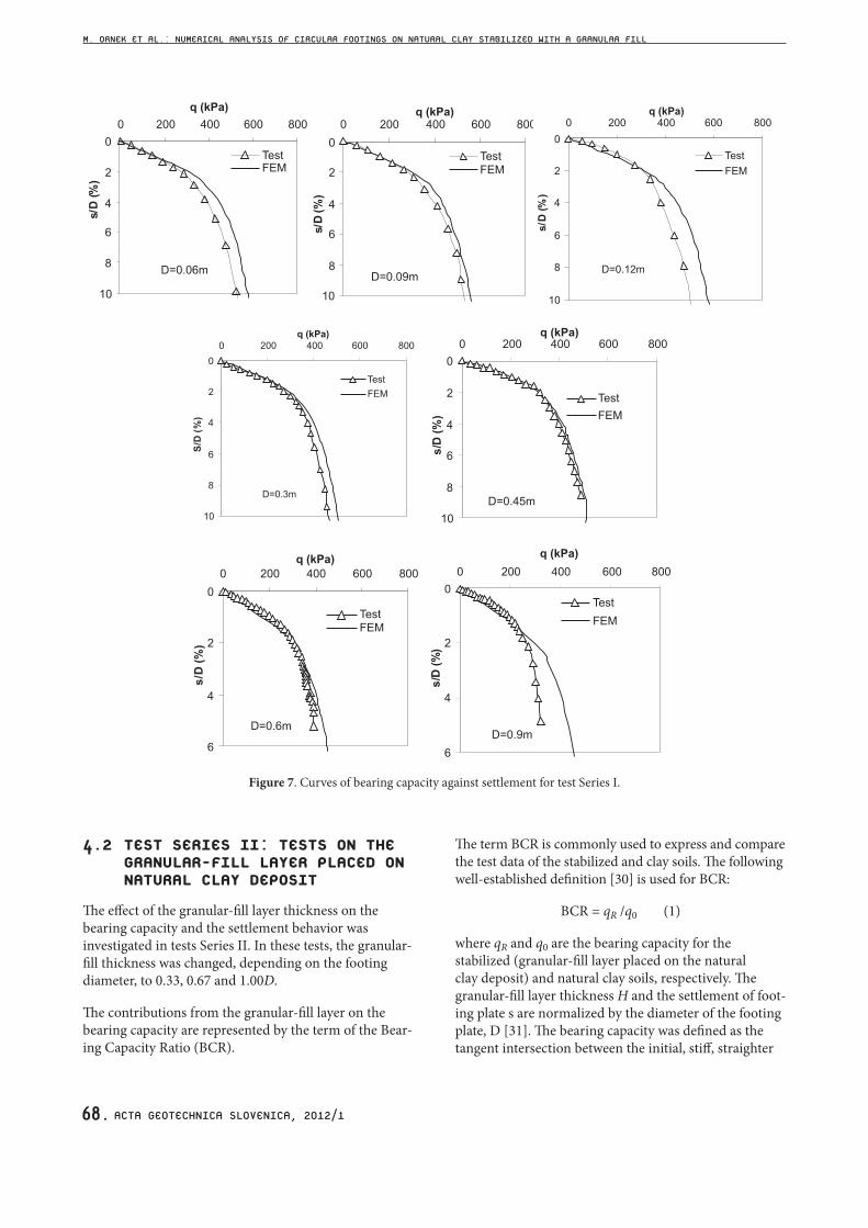
In test Series I, a total of seven in-situ tests were conducted using seven different circular foundations (diameters of 0.06, 0.09, 0.12, 0.30, 0.45, 0.60 and 0.90 m) rested on a natural clay deposit. The load-settlement curves for all sizes, including the numerical analysis, are presented in Figure 7. The horizontal and vertical axes show the bearing capacities and the settlement ratios, respectively. The settlement ratio (s/D) is defined as the ratio of the footing settlement (s) to the footing diameter (D), expressed as a percentage. It is clear from the figure that the vertical displacements predicted by the numerical analysis are in very good agreement with the experimental results. Since the load was applied directly through the natural clay soil in test Series I, the settle-ment pattern generally resembles a typical local shear failure and the maximum load bearing capacity was not clearly well defined in each case.
M. ORNEK ET AL.: NUMERICAL ANALYSIS OF CIRCULAR FOOTINGS ON NATURAL CLAY STABILIZED WITH A GRANULAR FILL
ACTA GEOTECHNICA SLOVENICA, 2012/168.
Figure 7. Curves of bearing capacity against settlement for test Series I.
4.2 TEST SERIES II: TESTS ON THE GRANULAR-FILL LAYER PLACED ON NATURAL CLAY DEPOSIT
The effect of the granular-fill layer thickness on the bearing capacity and the settlement behavior was investigated in tests Series II. In these tests, the granular-fill thickness was changed, depending on the footing diameter, to 0.33, 0.67 and 1.00D.
The contributions from the granular-fill layer on the bearing capacity are represented by the term of the Bear-ing Capacity Ratio (BCR).
The term BCR is commonly used to express and compare the test data of the stabilized and clay soils. The following well-established definition [30] is used for BCR:
BCR = qR /q0 (1)
where qR and q0 are the bearing capacity for the stabilized (granular-fill layer placed on the natural clay deposit) and natural clay soils, respectively. The granular-fill layer thickness H and the settlement of foot-ing plate s are normalized by the diameter of the footing plate, D [31]. The bearing capacity was defined as the tangent intersection between the initial, stiff, straighter
M. ORNEK ET AL.: NUMERICAL ANALYSIS OF CIRCULAR FOOTINGS ON NATURAL CLAY STABILIZED WITH A GRANULAR FILL
ACTA GEOTECHNICA SLOVENICA, 2012/1 69.
portion of the loading-pressure-settlement curve and the following steeper, straight portion of the curve [12]. All the test and numerical results were interpreted using this approach (Figure 8). It is also clear that the ultimate bearing-capacity values obtained from the experimental and numerical studies are very close to each other. The settlement ratio (s/D) is defined as the ratio of the footing settlement (s) to the footing diameter (D). The qu (ultimate bearing capacity) and s (settlement) values were obtained from load-settlement curves of the tests.
The field-test configurations of “D=0.12m-H/D=0.33” and “D=0.30m-H/D=0.33”, including the numerical
Figure 8. Determination of the ultimate bearing-capacity value.
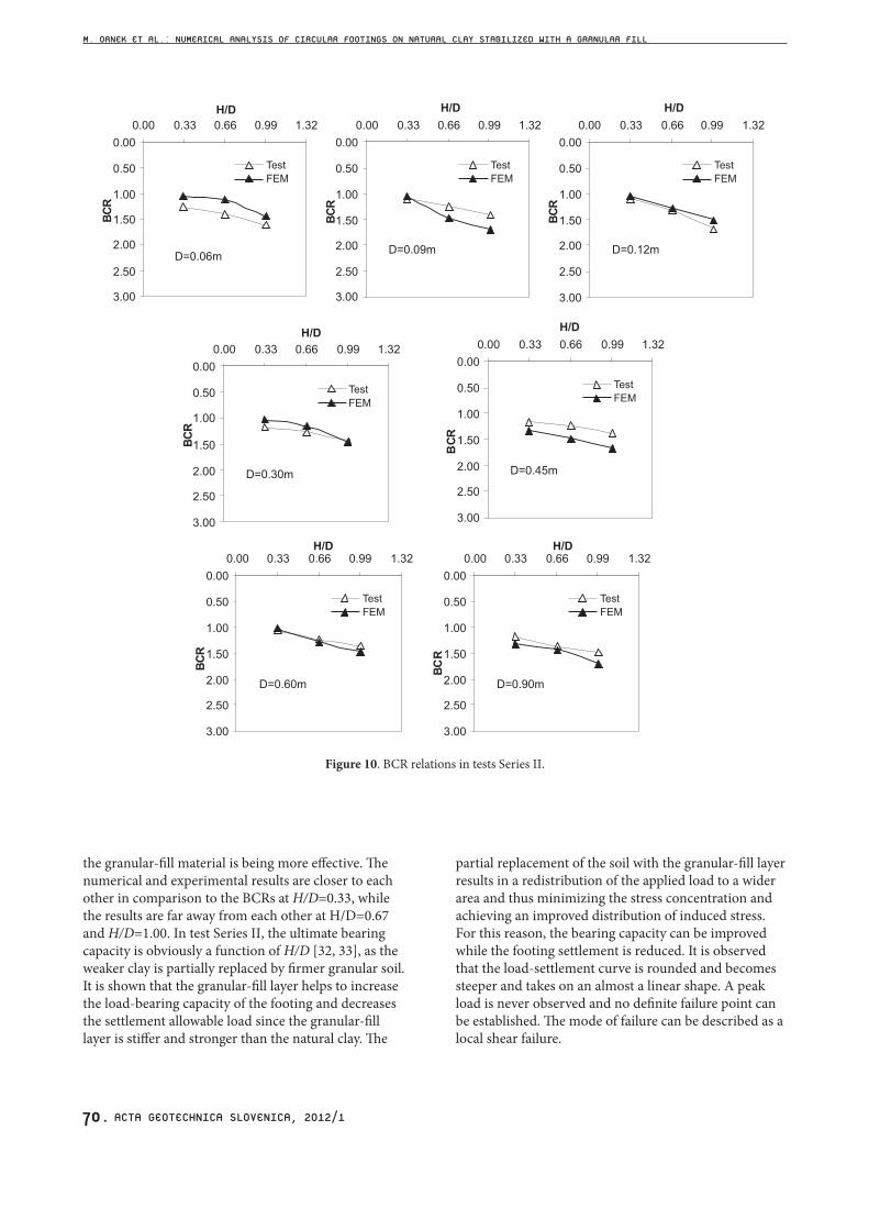
analysis, were selected to give typical examples in Figure 9. As seen from the figure, the vertical displacement predicted by the numerical analysis are in very good agreement with the experimental results. Figure 10 shows the relation of BCR to H/D ratio obtained from the numerical studies and the tests of Series II using the values of the ultimate bearing capacity evaluated using Equation 1. H/D is a ratio defined as the ratio of the granular-fill thickness (H) to the footing diameter (D). It is shown that the BCR increases with an increase in the granular-fill thickness for all footing diameters. The main reason for this phenomenon is that the thickness of the granular-fill material is increasing and
Figure 9. Curves of bearing capacity against settlement for test Series II.
a) D=0.12m; H/D=0.33 b) D=0.3m; H/D=0.33
M. ORNEK ET AL.: NUMERICAL ANALYSIS OF CIRCULAR FOOTINGS ON NATURAL CLAY STABILIZED WITH A GRANULAR FILL
ACTA GEOTECHNICA SLOVENICA, 2012/170.
the granular-fill material is being more effective. The numerical and experimental results are closer to each other in comparison to the BCRs at H/D=0.33, while the results are far away from each other at H/D=0.67 and H/D=1.00. In test Series II, the ultimate bearing capacity is obviously a function of H/D [32, 33], as the weaker clay is partially replaced by firmer granular soil. It is shown that the granular-fill layer helps to increase the load-bearing capacity of the footing and decreases the settlement allowable load since the granular-fill layer is stiffer and stronger than the natural clay. The
partial replacement of the soil with the granular-fill layer results in a redistribution of the applied load to a wider area and thus minimizing the stress concentration and achieving an improved distribution of induced stress. For this reason, the bearing capacity can be improved while the footing settlement is reduced. It is observed that the load-settlement curve is rounded and becomes steeper and takes on an almost a linear shape. A peak load is never observed and no definite failure point can be established. The mode of failure can be described as a local shear failure.
Figure 10. BCR relations in tests Series II.
M. ORNEK ET AL.: NUMERICAL ANALYSIS OF CIRCULAR FOOTINGS ON NATURAL CLAY STABILIZED WITH A GRANULAR FILL
ACTA GEOTECHNICA SLOVENICA, 2012/1 71.
5 SCALE EFFECT INVESTIGATION
5.1 DETAILS OF THE PARAMETRIC STUDY
A parametric study was carried out after obtaining a good relationship between the test and numerical results. A footing-size-based scale-effect analysis was performed under the clay soil (Analysis Series I: Analysis on the Natural Clay Deposit) and partial replacement (Analysis Series II: Analysis on the Granular-fill Layer Placed on Natural Clay Deposit) soil conditions. Six additional foot-ing diameters up to 25.0 m (1.2; 1.5; 3.0; 6.0; 12.0 and 25.0 m) were used in the analysis. In addition to the field tests, three different granular-fill thicknesses, 1.33D, 1.67D and 2.00D were used. The non-dimensional relationships between the footing diameter and the ultimate bearing-capacity/bearing-capacity ratio were presented with using seven different footing diameters (D=0.9m was also added) and six different granular-fill layer thicknesses (clay soil state, H/D=0 was also added). The footing size varies in the range between 0.06 m and 25.0 m.
5.2 ANALYSIS SERIES I: ANALYSIS ON THE NATURAL CLAY DEPOSIT
Terzaghi proposed the following relationship to define the ultimate bearing capacity qu for circular footings [34]:
1.3 0.3u c qq c N q N BNgg= + + (2)
where, c is the soil cohesion, B is the footing width and Nc , Nq , Nγ are Terzaghi’s bearing-capacity factors. In addition, q can also be identified as (γ Df), where Df is the footing depth.
In the tests and analysis made, the footings were placed at soil surface of the clay soil; therefore there are no contributions from the second and third parameters in Equation 2 to the footing-bearing capacity.
Then, the net bearing capacity (qu(net)) equation can be written as follows:
( )u net u cq c N= (3)
From Equation 3, the bearing capacity factor Nc is defined as:
( ) /c u net uN q c= (4)
For the local shear failure, the modified cohesion value (cu*) should be calculated as cu*=2cu / 3 [34]. Therefore, equation 4 is rearranged as follows;
/(1.3 *)c net uN q c= (5)
Figure 11 shows the relationship between the bearing-capacity factor Nc and the footing diameter D. The bear-ing-capacity factor Nc was back-calculated from Equa-tion 5 where cu* equals 50kPa and plotted to observe the footing-size effect. The bearing-capacity values were obtained from load-settlement curves using the method as mentioned in Figure 8. The Nc values are almost the same for all the footing sizes. The existence of a scale effect in the footing sizes rested on natural clay soils cannot be directly observed from these figures. Consoli et al. [35], Fellenium and Altaee [36] and Ismael [37] reported similar findings. These studies indicate that the footing resting on silty clay has no footing-size effect, if the settlement is expressed in a non-dimensional relative settlement of s/D reported similar findings. The studies performed by Consoli et al. [35] show that the behavior of the pressure to settlement (q/qu) to a diameter ratio (s/D) seems to be independent of the footing-plate size.
Figure 11. Variation of D with Nc for Series I.
5.3 ANALYSIS SERIES II: ANALYSIS ON THE GRANULAR-FILL LAYER PLACED ON NATURAL CLAY DEPOSIT
In the analysis Series II, the footing-size-effect investiga-tion was carried out with the granular-fill soil replace-ment beneath the footings. Figure 12 shows the plots of the ultimate bearing capacity (qu) versus footing diameter (D) for the analysis conducted on the soil replacement placed on a natural clay deposit. For a given value of H/D, the magnitude of the ultimate bearing capacity increases in a nonlinear manner with the footing diam-eter. The variation of the magnitudes of qu with the soil-replacement thickness (H/D) obtained from the analysis are shown in Figure 13. For a given value of D, the magnitude of qu increases with the increase in the soil-
M. ORNEK ET AL.: NUMERICAL ANALYSIS OF CIRCULAR FOOTINGS ON NATURAL CLAY STABILIZED WITH A GRANULAR FILL
ACTA GEOTECHNICA SLOVENICA, 2012/172.
replacement thickness H. For the values of H/D>1.33, the increasing trend in qu becomes decremental for footing diameters greater than about 12 m. This observation is true for all the soil-replacement thicknesses. For a given value of D, the magnitude of BCR increases with the increase in the soil replacement, H/D. The effect of the soil-replacement thickness minimizes after H>1.33D.
The variations of the magnitudes of BCR with the ratio of H/D obtained from the analysis are shown in Figure 14. Similar behavior was also obtained in Figure 13. The maximum value in BCR was obtained at H=2.0D for all the footing sizes.
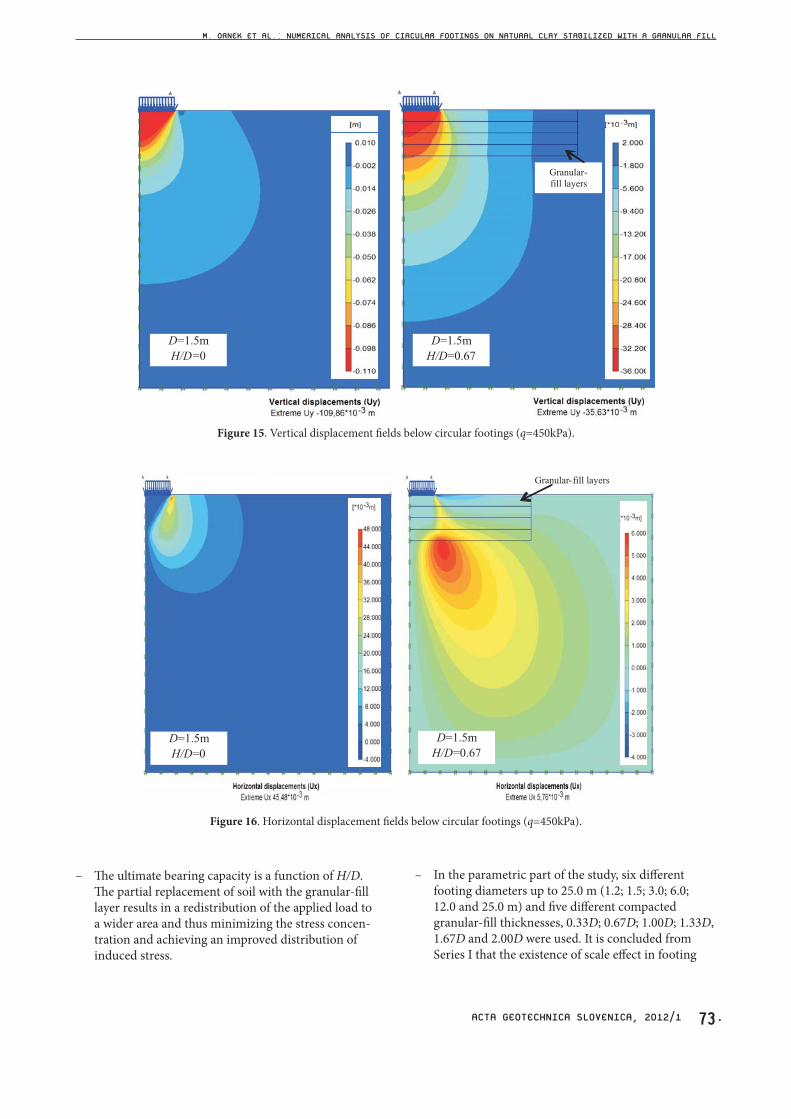
The finite-element method generates an effective analysis and evaluation of displacements, stress and forces in and around the soil, stabilized bodies and footing. Figures 15 and 16 show some typical examples of the resultant vertical and horizontal displacement fields below the 1.5-m-diameter circular footing for clay soil (H/D=0) and stabilized cases (H/D=0.67) at a loading pressure q=450kPa (this value is very close to the ultimate bear-ing capacity of the natural clay deposit). It can be seen that there is a clear reduction of the vertical and hori-zontal displacements for the stabilized case (compacted granular-fill bed over natural clay deposit) compared with the clay soil case (over natural clay deposit). The compacted granular-fill bed structure behaves as a rigid slab below the footing and distributes the load into the underlying ground. This reduces the vertical and lateral displacements, resulting in a uniform settlement.
6 CONCLUSIONS
This study is focused directly on a scale-effect investiga-tion in circular footings resting on natural clay deposits stabilized with compacted granular-fill layers. Based on the results from this investigation, the following main conclusions can be drawn:
– Vertical load increases with an increase in footing size. Vertical displacements predicted by the nume-rical analysis are in very good agreement with the experimental results.
– The field test results indicate that the use of partially replaced granular-fill layers over natural clay soil has considerable effects on the bearing capacity and the settlement characteristics.
– In the tests, granular-fill thickness (H) was changed depending on the footing diameter as 0.33, 0.67 and 1.00D. The bearing-capacity ratio (BCR) increases with an increase in the granular-fill thickness for all the footing diameter.
Figure 12. Variation of ultimate bearing capacity with footing diameter for Series II.
Figure 13. Variation of ultimate bearing capacity with granular-fill thickness for Series II.
Figure 14. Variation of bearing capacity ratio with granular-fill thickness for Series II.
M. ORNEK ET AL.: NUMERICAL ANALYSIS OF CIRCULAR FOOTINGS ON NATURAL CLAY STABILIZED WITH A GRANULAR FILL
– The ultimate bearing capacity is a function of H/D. The partial replacement of soil with the granular-fill layer results in a redistribution of the applied load to a wider area and thus minimizing the stress concen-tration and achieving an improved distribution of induced stress.
– In the parametric part of the study, six different footing diameters up to 25.0 m (1.2; 1.5; 3.0; 6.0; 12.0 and 25.0 m) and five different compacted granular-fill thicknesses, 0.33D; 0.67D; 1.00D; 1.33D, 1.67D and 2.00D were used. It is concluded from Series I that the existence of scale effect in footing
M. ORNEK ET AL.: NUMERICAL ANALYSIS OF CIRCULAR FOOTINGS ON NATURAL CLAY STABILIZED WITH A GRANULAR FILL
ACTA GEOTECHNICA SLOVENICA, 2012/174.
sizes resting on natural clay soils cannot be directly implied.
– The footing size-effect investigation was carried out with the partially replaced compacted granular-fill layer beneath the footings in Series II. For a given value of H/D, the magnitude of the ultimate bearing capacity increases in a nonlinear manner with the footing diameter. On the other hand, for a given value of D, the magnitude of qu increases with the increase in the compacted granular-fill layer thic-kness, H.
– The BCR values increase with an increase in H/Dand these values remain relatively constant whenH/D>1.33. The maximum values in BCR were obtai-ned at H=2.0D for all the footing sizes.
ACKNOWLEDGMENTS
The work presented in this paper was carried out with funding from TUBITAK (The Scientific and Techno-logical Research Council of Turkey) grant number 106M496, and Cukurova University Scientific Research Project Directorate grant number MMF2006D28.
REFERENCES
[1] Terzaghi, K. (1943). Theoretical soil mechanics. Wiley, NewYork.
[2] Cerato, A. B. and Lutenegger, A. J. (2007). Scale effects of shallow foundation bearing capacity on granular material. Journal of Geotechnical and Geoenvironmental Engineering, ASCE, 133(10), 1192-1202.
[3] Dewaiker, D. M. and Mohapatro, B. G. (2003). Computation of bearing capacity factor Nγ-Terzaghi’s mechanism. International Journal of Geomechanics, 3(1), 123-128.
[4] Siddiquee, M. S. A., Tanaka, T., Tatsuoka, F., Tani, K. and Morimoto, T. (1999). Numerical simulation of bearing capacity characteristics of strip footing on sand. Soils and Foundations, 39 (4), 93-109.
[5] Berry, D. S. (1935). Stability of granular mixtures. Proceedings of 38th Annual Meeting, (35), ASTM, Philadelphia, 491–507.
[6] Das, B. M. and Omar, M. T. (1994). The effects of foundation width on model tests for the bearing capacity of sand with geogrid reinforcement. Geotechnical and Geological Engineering, Technical Note (12), 133-141.
[7] De Beer, E. E. (1965). The scale effect in the trans-position of the results of deep-sounding tests on
the ultimate bearing capacity of pile sand caisson foundations. Geotechnique, 13(1), 39–75.
[8] Hettler, A. and Gudehus, G. (1988). Influence of the foundation width on the bearing capacity factor. Soils Foundation, 28(4), 81–92.
[9] Ueno, K., Miura, K. and Maeda, Y. (1998). Predic-tion of ultimate bearing capacity of surface footing with regard to size effects. Soils Foundation, 38 (3), 165–178.
[10] Zhu, F., Clark, J. I. and Phillips, R. (2001). Scale effect of strip and circular footings resting on dense sand. Journal of Geotechnical and Geoenvi-ronmental Engineering, ASCE 127(7), 613-621.
[11] Fukushima, H., Nishimoto, S. and Tomisawa, K. (2005). Scale effect of spread foundation loading tests using various size plates. Independent Admin-istrative Institution Civil Engineering Research Institute for Cold Region, 1-8.
[12] Adams, M. and Collin, J. (1997). Large model spread footing load tests on geosynthetic rein-forced soil footings. Journal of Geotechnical and Geoenvironmental Engineering, 123 (1), 66-72.
[13] Alawaji, H. A. (2001). Settlement and bearing capacity of geogrid-reinforced sand over collaps-ible soil. Geotextiles and Geomembranes, 19, 75-88.
[14] Dash, S. K., Sireesh, S. and Sitharam, T. G. (2003) Model Studies on circular footing supported on geocell reinforced sand underlain by soft clay. Geotextiles and Geomembranes, 21, 197-219.
[15] Deb, K., Sivakugan, N., Chandra, S. and Basudhar, P. K. (2007). Numerical analysis of multi-layer geosynthetic-reinforced granular bed over soft fill. Geotechnical and Geological Engineering, 25, 639-646.
[16] Ochiai, H., Watari, Y. and Tsukamoto, Y. (1996). Soil reinforcement practice for fills over soft ground in Japan. Geosynthetics International, 3 (1), 31-48.
[17] Otani, J., Hidetoshi, O. and Yamamoto, K. (1998). Bearing capacity analysis of reinforced foundations on cohesive soil. Geotextiles and Geomembranes, 16, 195-206.
[18] Thome, A., Donato, M., Consoli, N. C. and Graham, J. (2005). Circular footings on a cemented layer above weak foundation soil. Canadian Geotechnical Journal, 42, 1569-1584.
[19] Yin, J. H. (1997). Modeling geosynthetic-reinforced granular fills over soft soil. Geosynthetics Interna-tional, 4 (2), 165-185.
[20] ASTM. (1997). Standard test method for non repetitive static plate load tests of soils and flex-ible pavement components, for use in evaluation and design of airport and highway pavements, 112–113.
M. ORNEK ET AL.: NUMERICAL ANALYSIS OF CIRCULAR FOOTINGS ON NATURAL CLAY STABILIZED WITH A GRANULAR FILL
ACTA GEOTECHNICA SLOVENICA, 2012/1 75.
[21] Laman, M., Yildiz, A., Ornek, M. and Demir, A. (2009) Geogrid reinforcement on soft clay deposit” TUBITAK Scientific Research Project (No:106M496), Ankara, Turkey, 528p.
[22] Ornek, M. (2009). Geogrid reinforcement on soft clay deposits. PhD Thesis, University of Cukurova, Turkey, 318 p. (in Turkish).
[23] Laman, M. and Yildiz, A. (2007). Numerical stud-ies of ring foundations on geogrid-reinforced sand. Geosynthetics International, 14 (2), 1–13.
[24] Brinkgreve, R. B. J., Broere, W. and Waterman, D. (2004). Plaxis finite element code for soil and rock analysis, 2D –Version 8.6.
[25] Lehane, B. M. (2003). Vertical loaded shallow foundation on soft clayey silt. Proceedings of the Institution of Civil Engineers, Geotechnical Engi-neering, 17–26.
[26] Long, M.M. and O'riordan, O. (2001). Field behav-iour of very soft clays at the Athlone embank-ments. Geotechnique, 51 (4) 293-309.
[27] Osman, A. S. and Bolton, M. D. (2005). Simple plasticity-based prediction of the undrained settlement of shallow circular foundations on clay. Geotechnique, 55 (6), 435–447.
[28] Taiebat, H. A. and Carter, J. P. (2002). Bearing capacity of strip and circular foundations on undrained clay subjected to eccentric loads. Geotechnique, 52 (1), 61–64.
[29] Bolton, M.D. (1986). The strength and dilatancy of sands. Geotechnique, 36 (1), 65-78.
[30] Binquet, J. and Lee, K. L. (1975a). Bearing capacity tests on reinforced earth slabs. Journal of Geotech-nical Engineering Division, ASCE 101 (GT12), 1241-1255.
[31] Laman, M. and Yildiz, A. (2003). Model studies of ring footings on geogrid-reinforced sand. Geosyn-thetics International, 10 (5), 142-152.
[32] Hamed, J. T., Das, B. M. and Echelberger, W. F. (1986). Bearing capacity of a strip foundation on granular trench in soft clay. Civil Engineering for Practising and Design Engineers, Paragon Press 5 (5), 359-376.
[33] Madhav, M. R. and Vitkar P. P. 1978. Strip footing on weak clay stabilized with a granular trench or pile. Canadian Geotechnical Journal, 15 (4), 605-609.
[34] Das, B. M. (1999). Shallow foundations: bearing capacity and settlement. CRC Press, LLC.
[35] Consoli, N. C., Schnaid, F. and Milititsky, J. (1998). Interpretation of plate load tests on residual soil site. Journal of Geotechnical and Geoenvironmental Engineering, 124 (9), 857-867.
[36] Fellenium, B. H. and Altaee, A. (1994). Stress and settlement of footings in sand. Proceedings of
the American Society of Civil Engineers, ASCE, Conference on Vertical and Horizontal Deforma-tions for Foundations and Embankments, Geotech-nical Special Publication, GSP, 2(40), College Station 1760-1773.
[37] Ismael, N. F. (1985). Allowable bearing pressure from loading tests on Kuwaiti soils. Canadian Geotechnical Journal, 22 (2), 151-157.
M. ORNEK ET AL.: NUMERICAL ANALYSIS OF CIRCULAR FOOTINGS ON NATURAL CLAY STABILIZED WITH A GRANULAR FILL