D. Dai and Z. Sheng Vol. 24, No. 11 /November 2007 /J. Opt. Soc. Am. B 2853
Numerical analysis of silicon-on-insulator ridgenanowires by using a full-vectorial finite-
difference method mode solver
Daoxin Dai* and Zhen Sheng
Center for Optical and Electromagnetic Research, State Key Laboratory for Modern Optical Instrumentation,Zhejiang University, Hangzhou 310058, China and
Joint Research Center of Photonics of KTH (the Royal Institute of Technology, Sweden) and Zhejiang University,East Building 5, Zijingang Campus, Zhejiang University, Hangzhou 310058, China
. INTRODUCTIONn recent years, the silicon-on-insulator (SOI) platformas been one of the most attractive choices to realizeanophotonic wires and ultrasmall planar light wave cir-uit (PLCs) [1]. There have been developed various Si-anowire-based photonic integrated devices, such as di-ectional couplers [2,3], multimode interference (MMI)ouplers [4,5], Mach–Zehnder interferometers (MZIs) [6],rrayed-waveguide grating (AWG) (de)multiplexers [7,9],nd microring/disk resonators [10]. The work of most pub-ished papers was focused on SOI rectangular nanowires,hich have an undercut Si core layer (i.e., some of theiO2 insulator layer beneath the Si core layer is etched).owever, this will introduce some drawbacks, such asreventing integration with active electronic functional-ties e.g., metal-oxide-semiconductor (MOS) transistors orctive elements with p-n junctions [1,11–13].There are some theoretical analyses for SiO2 nanofi-
ers [14] and SOI rectangular nanowires [15]. However,ittle has been reported so far on the characteristic analy-is of SOI ridge nanowires. In our previous work [16], weave given detailed analyses on the characteristics of SOIidge waveguides with large cross sections, including theending loss and the birefringence. In this paper, we use aull-vectorial finite-difference method (FDM) with a per-ectly matched layer (PML) treatment [17] for the modealculation of SOI ridge nanowires, including the single-ode condition, the birefringence, and the bending loss,hich are different from the case of large SOI ridgeaveguides.
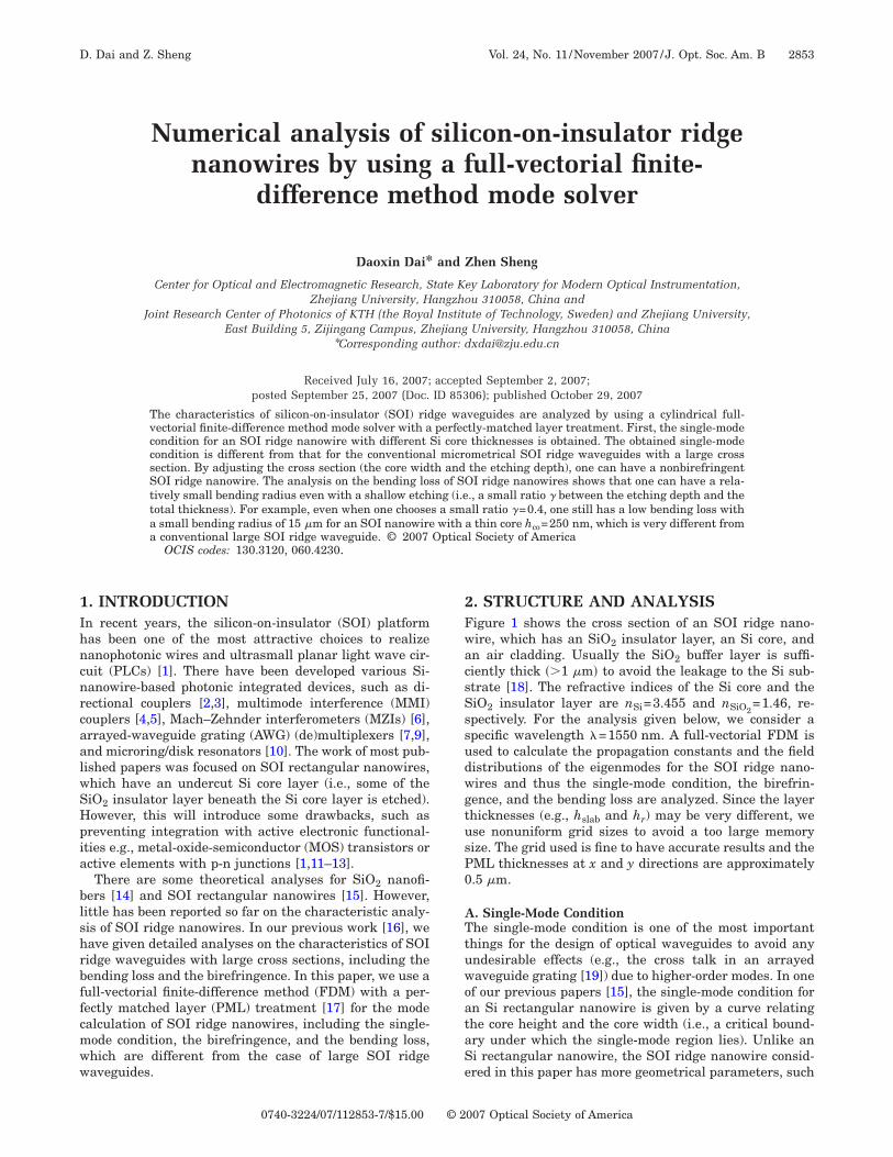
. STRUCTURE AND ANALYSISigure 1 shows the cross section of an SOI ridge nano-ire, which has an SiO2 insulator layer, an Si core, andn air cladding. Usually the SiO2 buffer layer is suffi-iently thick ��1 �m� to avoid the leakage to the Si sub-trate [18]. The refractive indices of the Si core and theiO2 insulator layer are nSi=3.455 and nSiO2
=1.46, re-pectively. For the analysis given below, we consider apecific wavelength �=1550 nm. A full-vectorial FDM issed to calculate the propagation constants and the fieldistributions of the eigenmodes for the SOI ridge nano-ires and thus the single-mode condition, the birefrin-ence, and the bending loss are analyzed. Since the layerhicknesses (e.g., hslab and hr) may be very different, wese nonuniform grid sizes to avoid a too large memoryize. The grid used is fine to have accurate results and theML thicknesses at x and y directions are approximately.5 �m.
. Single-Mode Conditionhe single-mode condition is one of the most important
hings for the design of optical waveguides to avoid anyndesirable effects (e.g., the cross talk in an arrayedaveguide grating [19]) due to higher-order modes. In one
f our previous papers [15], the single-mode condition forn Si rectangular nanowire is given by a curve relatinghe core height and the core width (i.e., a critical bound-ry under which the single-mode region lies). Unlike ani rectangular nanowire, the SOI ridge nanowire consid-red in this paper has more geometrical parameters, such
007 Optical Society of America
awcrpsctctwa
mdllnctusttc[TttmwcchPttlPftchtf
wfiP�
thtTrafimtstsof2ta
soztcH=fztabmsEhccbdhS=Bh=EorstdEbo2
tlfi�0se
2854 J. Opt. Soc. Am. B/Vol. 24, No. 11 /November 2007 D. Dai and Z. Sheng
s the core height hco, the ridge height hr, and the coreidth wco, which makes the analysis of the single-mode
ondition more complicated. For conventional large SOIidge waveguides, the single-mode condition is given sim-ly by using the normalized rib width and the normalizedlab height (normalized with the total height of the Siore) [16]. However, in the case of the SOI ridge nanowire,he Si core layer is very thin (only several hundred mi-rometers) and thus the characteristics are sensitive tohe Si thickness. Therefore, here we consider the casesith different core heights (hco=250, 300, 350, 400, 450,nd 500 nm).For an SOI rectangular nanowire, the single-mode–ultimode boundary can be easily determined by the con-
ition that the higher-order mode has an effective indexower than the refractive index nSiO2
of the SiO2 insulatorayer. However, the case is very different for an SOI ridgeanowire. Even when the higher-order order is close to beut off, the effective index is usually still much largerhan the insulator index nSiO2
. Consequently we shouldse a different criterion for the determination of theingle-mode–multimode boundary (i.e., the cut-off condi-ion of the first higher-order mode). We note that whenhe eigenmode is close to the cutoff most of the power isonfined in the slab region instead of the ridge core regione.g., see the field distribution E21�x ,y� given in Fig. 2(e)].herefore, in this paper one of the cutoff conditions forhe higher-order mode is given by Pco�Pco0
, where Pco ishe power confined in the ridge area for a higher-orderode, Pco0
is a given value. Here we choose Pco0=0.05,
hich gives a relatively critical single-mode condition. Ifhoosing a larger Pco0
, one will have a relaxed single-modeondition. We also note that in some cases the firstigher-order mode has relatively large confined powerco��Pco0
� while the effective index is much smaller thanhe refractive index nSiO2
of the SiO2 insulator layer. Inhis case the first higher-order mode has a large leakageoss to the substrate. Therefore, besides the conditionco�Pco0
, in this paper we use an additional requirementor the cutoff condition of the first higher-order mode, i.e.,he leakage loss Llk is larger than 200 dB/mm. Such aondition guarantees that the cross talk due to theigher-order modes is smaller than −20 dB after a dis-ance of 100 �m (which is the typical order of the lengthor an Si nanowire device).
For each case with a given core height, we scan the coreidth wco and the ridge height hr, and check whether therst higher-order mode is cut off by using the conditionco�Pco0
and Llk�200 dB/mm. For a fixed ratio�=h /h �, the cut-off width w is obtained by reducing
Fig. 1. (Color online) Cross section of an Si ridge nanowire.
r co cutoff
he core width wco with a step of 20 nm until the firstigher-order mode is cut off. Figures 2(a) and 2(b) showhe cutoff width wcutoff of the first higher-order TE andM modes for cases with different core heights hco as theatio � increases. The curve indicates the critical bound-ry under which the single-mode region lies. From thisgure, one can easily choose the core width for a single-ode SOI ridge nanowire when the core height hco and
he ratio � are given. Since the SOI ridge nanowire istrongly polarization dependent, the single-mode condi-ions for the TE and TM modes are very different [ashown in Figs. 2(a) and 2(b)]. From Figs. 2(a) and 2(b),ne also sees that the single-mode conditions are very dif-erent when the core height hco increases from50 to 500 nm. Here we give a detailed explanation forhe case of TE mode as follows (one can get a similarnalysis for the TM mode).For the TE mode, when the SOI ridge nanowire has a
mall core height (e.g., hco=250 nm), the first higher-rder mode is E21�x ,y� (which has two peaks at the hori-ontal direction and one peak in the vertical direction). Inhis case, the single-mode conditions given in Fig. 2(a)orrespond to the cutoff boundary for the mode E21�x ,y�.owever, for the case with a large core height (e.g., hco500 nm), the first higher-order mode will be alternated
rom E21�x ,y� to E12�x ,y� (which has one peak at the hori-ontal direction and two peaks in the vertical direction) ashe ratio � increases. This can be observed in Figs. 2(d)nd 2(e). In this case, the single-mode condition is giveny the smaller one between the cutoff widths for theodes of E21�x ,y� and E12�x ,y�. For example, Fig. 2(c)
hows the cutoff widths for the modes of E21�x ,y� and12�x ,y� as the ratio � increases from 0.4 to 1.0 whenco=500 nm. When �=1.0, the SOI ridge nanowire be-omes an Si rectangular nanowire (whose single-modeondition is given in [15]). To make it understoodetter, in Figs. 2(d) and 2(e) we demonstrate the fieldistributions of the fundamental mode and the firstigher-order mode for both polarizations in the presentOI ridge nanowires with hco=500 nm when �� ,wco��0.6,0.66 �m�, �0.8,0.4 �m�, respectively [see points A,in Fig. 2(a)]. From these figures, one sees that the first
igher-order TE mode is E21�x ,y� when �� ,wco��0.6,0.66 �m� and the higher-order TE mode becomes12�x ,y� when �� ,wco�= �0.8,0.4 �m�. Since the higher-rder TE mode is close to the cutoff boundary for the cur-ent case [see Fig. 2(a)], the modal field extends to thelab region remarkably [see E21�x ,y� in Fig. 2(d)]. In con-rast, the field distributions of the TM modes have veryifferent results. The first higher-order TM mode is21�x ,y� for both cases and far away from the cutoffoundary. This is why the single-mode condition is seri-usly polarization dependent [as shown in Figs. 2(a) and(b)].Figure 2(a) also shows that when the ratio � is rela-
ively small (e.g., ��0.7) the SOI ridge nanowire with aarger core height has a larger cutoff width wcutoff for therst higher-order mode. For example, when one chooses=hr /hco=0.5, the cutoff widths wcutoff are approximately.7 and 0.56 �m for the cases of hco=500 and 250 nm, re-pectively, which looks unreasonable. Actually, this can bexplained qualitatively as follows. Although an effective
Fcnw
D. Dai and Z. Sheng Vol. 24, No. 11 /November 2007 /J. Opt. Soc. Am. B 2855
ig. 2. (Color online) (a) Single-mode conditions of the TE mode for Si ridge nanowires with different core heights; (b) single-modeonditions of the TM mode for Si ridge nanowires with different core heights; (c) cutoff width of the higher-order TE modes in an Si ridgeanowire when hco=500 nm; (d) field distributions of the fundamental mode and the first higher-order mode when hco=500 nm, �=0.6,
co=0.66 �m; (e) field distributions of the fundamental mode and the first higher-order mode when hco=500 nm, �=0.8, wco=0.4 �m.
iwEw−thcl=tootlsocsS
BTttUtmSg
octoisnu
whStpfr
wTg
zwfgsrcFp
ra+stnhvf=de�or
tcrntv[TPfgdma[
ntomsh−2uM
CTt=d
Fe
2856 J. Opt. Soc. Am. B/Vol. 24, No. 11 /November 2007 D. Dai and Z. Sheng
ndex method (EIM) is not accurate for SOI nanowires, weould like to use it for a qualitative analysis. By using anIM, an SOI ridge nanowire can be equivalent to a slabaveguide with a refractive index contrast �n�=neff�coneff�cl�, where the indices neff�co and neff�cl of the core and
he cladding are determined by the thicknesses of the coreeight hco and the slab height hslab, respectively. Here weonsider the TE polarization. Figure 3 shows the calcu-ated index contrast �n as the ratio increases when hco250, 350, 400, and 500 nm. From this figure, one sees
hat for the case with a relatively small ratio � ��0.76�ne has a larger index contrast �n and thus a larger cut-ff width wcutoff when the core height hco is smaller. Whenhe ratio is close to 1, a larger core height introduces aarger index contrast �n (see Fig. 3) and consequently amaller cutoff width [see Fig. 2(a)]. Furthermore, whenne chooses a small � for some specific designs, a smallore height (e.g., hco=250 nm) is preferred to achieve amall bending radius (which will be discussed more inubsection 2.C).
. Birefringencehe birefringence B of an optical waveguide is defined ashe difference between the effective refractive indices ofhe TE and TM fundamental modes, i.e., B=nTE-nTM.sually the birefringence mainly results from the aniso-
ropy of the refractive index distribution due to the geo-etrical asymmetry or the stresses [20]. For the presentOI ridge nanowire with an air cladding, the birefrin-ence is mainly introduced by its geometrical asymmetry.
Figures 4(a)–4(f) show the geometrical birefringence Bf SOI ridge nanowires with different ratios � for theases of hco=500, 450, 400, 350, 300, and 250 nm, respec-ively, as the core width wco increases. From these figures,ne sees that the birefringence of an SOI ridge nanowires usually very large (at the order of 10−1) when the crossection is not designed optimally. Therefore, an Si-anowire-based PLC device without an optimal designsually has a serious polarization dependency [8].In Figs. 4(a)–4(f), we consider only SOI ridge nanowires
ith a ridge width ranging from larger than 250 nm toco+100 nm. When the ridge width wco is very large, theOI rib waveguide behaves like a slab waveguide (withhickness hco for the guiding core layer) and thus has aositive birefringence. Thus, for any value of �, the bire-ringence approaches the same positive value (i.e., the bi-efringence for a slab waveguide of thickness hco) when
ig. 3. (Color online) Index contrast �n �=neff�co−neff�cl� of thequivalent slab waveguide as the ratio � increases.
co becomes very large (see the curves in Figs. 4(a)–4(f)).his is similar to that for a conventional SOI ridge wave-uide with a large cross section [16].
When the ridge width wco is very small (approachesero), the SOI ridge nanowire should behave like a slabaveguide with a thickness hslab (other than hco). There-
ore, in this case the birefringence of the SOI rib wave-uide also trends to a positive value. This has been ob-erved in a conventional SOI ridge waveguide. For SOIidge nanowires, however, the fundamental mode may beut off when the ridge width is very small. Therefore, inigs. 4(a)–4(f), the design with a small ridge width and aositive birefringence is not shown.From these figures, one sees that in most cases the bi-
efringence monotonously varies from a positive value tonegative one when the ridge width decreases from hco100 nm [see the curves of hco=350, 300, and 250 nmhown in Figs. 4(a)–4(f)]. In this case, one obtains an op-imal ridge width wco1
for a zero-birefringent SOI ridgeanowire. For the case with a relatively large hco (e.g.,co�400 nm), one can see that there is a nonmonotonousariation of the birefringence as the ridge width decreasesrom �hco+100 nm� to 250 nm [see the curve of hco500 nm and �=0.72 in Fig. 4(a)]. When the ridge widthecreases further, a positive birefringence appears as thexplanation and two zero-birefringent points wco1
, wco2wco1
�wco2� can be obtained. Considering the desirability
f a good mode confinement, the large nonbirefringentidge width wco1
is preferred.Figure 5 shows the nonbirefringent ridge width wco1
forhe cases with different core heights as the ratio � in-reases. From this figure, one can easily choose the opticalidge width wco, the ratio �, and the core height hco for aonbirefringent SOI ridge nanowire. We also note thathe fabrication tolerance is very small. For example, theariation of the ridge width should be as small as 1 nm21] when a birefringence smaller than 10−4 is required.herefore, in order to obtain a polarization-insensitiveLC device based on optimal SOI ridge nanowires, the
abrication should be controlled carefully to minimize theeometrical birefringence due to the fabrication-inducedeformation of the cross section. Then the minimized geo-etrical birefringence can be compensated by introducingpostcompensation process (e.g., the thermal oxidation
20]).On the other hand, this large birefringence of SOI ridge
anowires makes it possible to design a compact polariza-ion splitter (e.g., based on a MZI). From Figs. 4(a)–4(f),ne sees that a small variation of the core width willodify the birefringence greatly due to the small cross
ection and the strong confinement. For example, whenco=500 nm and �=1, the birefringence is reduced from0.7 to −0.23 by increasing the ridge width from50 nm to 350 nm. In this case, it is possible to design anltrashort polarization splitter by using an asymmetricalZI including two arms with different widths.
. Bending losshe bending loss includes the pure bending loss and the
ransition loss. The pure bending loss Lp is given by Lp20 log�exp�−� /2�iR�� (dB), where R is the bending ra-ius, � is the imaginary part of the propagation constant
i
�dbaancrwFaFcctbTfifebiwtst
hiwhwatcd6
Fc
Fg
Fi
D. Dai and Z. Sheng Vol. 24, No. 11 /November 2007 /J. Opt. Soc. Am. B 2857
. The transition loss is estimated by overlapping the fun-amental modal fields of the straight section and theending section [22]. Both the propagation constants �nd the modal field distributions E�x ,y� are obtained fromfull-vectorial FDM mode solver in a cylindrical coordi-
ate system (with a PML boundary treatment). Here theylindrical coordinate system is used to obtain an accu-ate and convenient calculation of eigenmodes for bendingaveguides [17]. Here we consider the TE polarization.igure 6(a) shows the calculated pure bending loss Lp ofn SOI ridge nanowire with a core height of hco=250 nm.rom this figure, one sees that the pure bending loss in-reases almost exponentially as the bending radius de-reases, which is similar to the case of a conventional op-ical waveguide. In this figure, one also sees that theending loss decreases greatly when the ratio increases.his is because a larger ratio introduces a stronger con-nement (see Fig. 3). To achieve a small bending radiusor a high integration density, a large ratio � (i.e., a deeptching) is preferred. For example, the bending radius cane as small as 2 �m when one chooses �=0.9. The bend-ng loss can be reduced slightly by choosing a larger coreidth wco. On the other hand, the core width is limited by
he single-mode condition (see Fig. 1). Therefore, onehould choose an appropriate core width to minimize theotal bending loss and satisfy the single-mode condition.
ig. 4. (Color online) Birefringence of an SOI ridge nanowire wreases: (a) hco=500, (b) hco=450, (c) hco=400, (d) hco=350, (e) hco
ig. 5. (Color online) Optimal core width wco1for a nonbirefrin-
ent SOI ridge nanowire as the ratio � increases.
Here we also consider the case with a thicker core (e.g.,co=500 nm), and the calculated bending loss Lp is shown
n Fig. 6(b). From Figs. 6(a) and 6(b), one sees the casesith different thicknesses (hco=250 nm and hco=500 nm)ave similar pure bending losses as the ratio and the coreidth increase. We note that the SOI ridge nanowire withlarger core height hco has a smaller bending loss when
he ratio � is very large ���0.9�. Here we consider thease of wco=460 nm as an example (the other case withifferent widths has a similar result). From Figs. 6(a) and(b), one sees that when �=0.9 the pure bending loss of a
fferent core heights and different ratios � as the core width in-(f) hco=250 nm.
ig. 6. (Color online) Pure bending loss as the bending radiusncreases. (a) h =250, (b) h =500 nm.
ith di=300,
co co
b(orw=6ea�
ci[lartlfstdjtm
ai�e
=ef
3IccttpSsaaitendofTt
ATajo
R
Fc
2858 J. Opt. Soc. Am. B/Vol. 24, No. 11 /November 2007 D. Dai and Z. Sheng
ending R=2 �m for the case of hco=250 nm is very smallapproximately 3.5210−4 dB) while the loss for the casef hco=500 nm is even smaller (approximately 3.0110−5 dB). However, the situation is opposite when the
atio � becomes smaller (e.g., ��0.78). For example,hen �=0.6, the pure bending losses of a bending R7.5 �m for the cases of hco=250 nm and hco=500 nm are.410−5 and 0.37 dB, respectively. This is because thequivalent slab waveguide of an SOI ridge nanowire withlarger core height will have a smaller the index contrastwhen the ratio � is relatively small (see Fig. 3).Figures 7(a) and 7(b) show the transition losses for the
ases of hco=250 nm and hco=500 nm. The transition losss estimated by using an overlapping integral method22]. From Figs. 6 and 7, one sees that the pure bendingoss increases much more rapidly than the transition losss the bending radius decreases. For the case with a largeatio ���0.6�, the transition loss is usually larger thanhe pure bending loss, which indicates that the transitionoss is the dominant one of the total bending loss. There-ore, for a design with straight-bending junctions, onehould pay more attention to the transition loss otherhan the pure bending loss. On the other hand, when oneesigns a bending structure without straight-bendingunctions (e.g., microring resonators), one can determinehe minimal bending radius according to the allowableinimal bending loss.From the analysis of the bending loss shown in Figs. 6
nd 7, we note that one can have a relatively small bend-ng radius even with a shallow etching (i.e., a small ratio
between the etching depth and the total thickness). Forxample, for an SOI nanowire with a thin core hco
ig. 7. (Color online) Transition loss as the bending radius in-reases. (a) h =250, (b) h =500 nm.
co co
250 nm, the bending radius can be as small as 15 �mven when a small ratio �=0.4 is used, which is very dif-erent from a conventional large SOI ridge waveguide.
. CONCLUSIONn this paper, we have given a detailed analysis for theharacteristics of SOI ridge nanowires by using a cylindri-al full-vectorial FDM with a perfectly matched layerreatment. It has been shown that the single-mode condi-ion of an SOI ridge nanowire is strongly polarization de-endent and very different from that of a conventionalOI ridge waveguide with a large cross section. The de-ign for nonbirefringent SOI ridge nanowires has beenchieved by adjusting the cross section (the core widthnd the etching depth). We also have evaluated the bend-ng loss of SOI ridge nanowires and theoretically shownhat a relatively small bending radius can be achievedven with a small ratio � (i.e., a shallow etching). We alsoote that the characteristics of SOI ridge nanowires areependent on the wavelength. Fortunately, in the windowf �1500–1600� nm, the single-mode condition, the bire-ringence, and the bending loss do not change much.herefore, one can choose the waveguide parameters ini-
ially from the results given in this paper.
CKNOWLEDGMENTShis project was supported by research grants (20061343nd 2006R10011) of the provincial government of Zhe-iang Province of China, the National Science Foundationf China (60607012 and 60688401).
EFERENCES1. M. Soltani, S. Yegnanarayanan, and A. Adibi, “Ultra-high
2. H. Yamada, T. Chu, S. Ishida, and Y. Arakawa, “Opticaldirectional coupler based on Si-wire waveguides,” IEEEPhoton. Technol. Lett. 17, 585–587 (2005).
3. H. Fukuda, K. Yamada, T. Tsuchizawa, T. Watanabe, H.Shinojima, and S. Itabashi, “Ultrasmall polarizationsplitter based on silicon wire waveguides,” Opt. Express 14,12401–12408 (2006).
4. H. Chen and A. W. Poon, “Low-loss multimode-interference-based crossings for silicon wire waveguides,”IEEE Photon. Technol. Lett. 18, 2260–2262 (2006).
5. D. Dai and S. He, “Optimization of ultracompactpolarization-insensitive multimode interference couplersbased on Si nanowire waveguides,” IEEE Photon. Technol.Lett. 18, 2017–2019 (2006).
6. F. Ohno, T. Fukazawa, and T. Baba, “Mach–Zehnderinterferometers composed of �-bends and �-branches in aSi photonic wire waveguide,” Jpn. J. Appl. Phys., Part 1 44,5322–5323 (2005).
7. K. Sasaki, F. Ohno, A. Motegi, and T. Baba, “Arrayedwaveguide grating of 7060 �m2 size based on Si photonicwire waveguides,” Electron. Lett. 41, 801–802 (2005).
8. D. Dai, L. Liu, L. Wosinski, and S. He, “Design andfabrication of ultra-small overlapped AWG demultiplexerbased on -Si nanowire waveguides,” Electron. Lett. 42,400–402 (2006).
9. P. Dumon, W. Bogaerts, D. Van Thourhout, D. Taillaert, R.Baets, J. Wouters, S. Beckx, and P. Jaenen, “Compactwavelength router based on a silicon-on-insulator arrayed
1
1
1
1
1
1
1
1
1
1
2
2
2
D. Dai and Z. Sheng Vol. 24, No. 11 /November 2007 /J. Opt. Soc. Am. B 2859
waveguide grating pigtailed to a fiber array,” Opt. Express14, 664–669 (2006).
0. D.-X. Xu, A. Densmore, P. Waldron, J. Lapointe, E. Post, A.Delâge, S. Janz, P. Cheben, J. H. Schmid, and B.Lamontagne, “High bandwidth SOI photonic wire ringresonators using MMI couplers,” Opt. Express 15,3149–3155 (2007).
1. O. Boyraz and B. Jalali, “Demonstration of a silicon Ramanlaser,” Opt. Express 12, 5269–5273 (2004).
2. C. Li, L. Zhou, and A. W. Poon, “Silicon microring carrier-injection-based modulators/switches with tunableextinction ratios and OR-logic switching by usingwaveguide cross-coupling,” Opt. Express 15, 5069–5076(2007).
3. H. Rong, R. Jones, A. Liu, O. Cohen, D. Hak, A. Fang, andM. Paniccia, “A continuous-wave Raman silicon laser,”Nature 433, 725–728 (2005).
4. L. Tong, J. Lou, and E. Mazur, “Single-mode guidingproperties of subwavelength-diameter silica and siliconwire waveguides,” Opt. Express 12, 1025–1035 (2004).
5. D. Dai, Y. Shi, and S. He, “Characteristic analysis ofnanosilicon rectangular waveguides for planar light-wavecircuits of high integration,” Appl. Opt. 45, 4941–4946(2006).
6. D. Dai and S. He, “Analysis of the birefringence of asilicon-on-insulator rib waveguide,” Appl. Opt. 43,1156–1161 (2004).
7. N. N. Feng, G. R. Zhou, C. L. Xu, and W. P. Huang,“Computation of full-vector modes for bending waveguideusing cylindrical perfectly matched layers,” J. LightwaveTechnol. 20, 1976–1980 (2002).
8. P. Bienstman, S. Selleri, L. Rosa, H. P. Uranus, W. C. L.Hopman, R. Costa, A. Melloni, L. C. Andreani, J. P.Hugonin, P. Lalanne, D. Pinto, S. S. A. Obayya, M. Dems,and K. Panajotov, “Modelling leaky photonic wires: a modesolver comparison,” Opt. Quantum Electron. 38, 731–759(2006).
9. M. Kohtoku, T. Hirono, S. Oku, Y. Kadota, Y. Shibata, andY. Yoshikuni, “Control of higher order leaky modes indeep-ridge waveguides and application to low-crosstalkarrayed waveguide gratings,” J. Lightwave Technol. 22,499–508 (2004).
0. S. Janz, P. Cheben, D. Dalacu, A. Delge, A. Densmore, B.Lamontagne, M.-J. Picard, E. Post, J. H. Schmid, P.Waldron, D.-X. Xu, K.-P. Yap, and W. N. Ye, “Microphotonicelements for integration on the silicon-on-insulatorwaveguide platform,” IEEE J. Sel. Top. Quantum Electron.12, 1402–1415 (2006).
1. H. Fukuda, K. Yamada, T. Tsuchizawa, T. Watanabe, H.Shinojima, and S. Itabashi, “Ultrasmall polarizationsplitter based on silicon wire waveguides,” Opt. Express 14,12401–12408 (2006).
2. D. Dai and S. He, “Analysis for characteristics of bent ribwaveguides,” J. Opt. Soc. Am. A 21, 113–121 (2004).


![119 Nanowires 4. Nanowires - Nanowires 4. Nanowires ... written about carbon nanotubes [4.57–59], which can be ... nanowires of a large variety of materials ...](https://static.documents.pub/doc/80x56/5abfd11e7f8b9a5d718eba2b/119-nanowires-4-nanowires-nanowires-4-nanowires-written-about-carbon-nanotubes.jpg)


