NUMERICAL ESTIMATES OF COMPOSITE SANDWICH RESPONSE UNDER QUASI STATIC INDENTATION Alberto Zinno 1 , Charles E. Bakis 2 and Andrea Prota 1 1 Department of Structural Engineering, University of Naples “Federico II” Via Claudio 21 - 80125 Naples, Italy. [email protected][email protected]2 Department of Engineering Science and Mechanics, Pennsylvania State University 212 Earth and Engineering Science Building – University Park PA 16802, United States. [email protected]Abstract The present work investigates the numerical modeling of sandwich structures with GFRP or CFRP face sheets and Nomex core under quasi static indentation. The study deals with a 2D configuration, where a sandwich beam is indented by a rigid cylinder across the whole width of the beam. The ABAQUS finite element package is used to model the indentation response of the beams. Geometrical non-linearities are including the contact problem are taken into accouny. The purpose of the numerical modelling is to develop reliable 2D simulations of the non-linear response for use in future investigations of failure modes caused by indentation. In order to verify the finite element model, an analytical approach is developed. The analytical model is based on a higher-order sandwich beam theory that includes the variational principles to include the transverse flexibility of the core. 1. Introduction Sandwich composite structures consist of two thin, stiff and strong fiber reinforced composite face sheets (skins) separated by a thick layer of low density material (core) which may be much less stiff and strong. The role of the face sheets, due to the higher elastic properties, is to resist to bending and in-plane loads, while the transverse shear loads are sustained by the core. The bending stiffness of this arrangement is very much greater than that of a single solid plate of same total weight made of the same materials as the faces. For this reason composite sandwich structures are widely used in high- performance applications where weight must be kept to a minimum, for example aerospace structures, high-speed marine craft and trains or racing cars. However the nature of core materials gives to these structures a low transverse stiffness, causing local bending under concentrated loads. As a result, sandwich structures are susceptible to local damages due to handling, interaction with attached structures or transverse impact. Usually, the local failure starts in the core and results in core crushing, face– core debonding and (or) residual dent formation and, therefore, substantial reduction of the structural strength. Fundamental analyses of sandwich beams such as that presented by Allen [1] and Plantema [2], assume that the core is incompressible in the out-of-plane direction. These models further assume that the skins have only bending rigidity while the core has only shear rigidity. This approach is appropriate for sandwich structures with incompressible cores. To model the local effects at the load points for non-metallic honeycomb sandwich panels with low transverse stiffness, deformation of the core in the vicinity of the applied loads must be considered. Accordingly the elastic foundation model has been applied to this problem [3,4]. However foundation models neglect interactions between the top and bottom skins. The non-planar deformed cross-section of the sandwich beams, observed in experiments, suggests a model that allows non- linear variations of in-plane and vertical displacements through the thickness of the core. Frostig and Baruch [5-7] used variational principles to develop a higher-order
Transcript
NUMERICAL ESTIMATES OF COMPOSITE SANDWICH RESPONSE UNDER QUASI STATIC INDENTATION
Alberto Zinno 1, Charles E. Bakis 2 and Andrea Prota 1
1 Department of Structural Engineering, University of Naples “Federico II” Via Claudio 21 - 80125 Naples, Italy.
212 Earth and Engineering Science Building – University Park PA 16802, United States. [email protected]
Abstract
The present work investigates the numerical modeling of sandwich structures with GFRP or CFRP face sheets and Nomex core under quasi static indentation. The study deals with a 2D configuration, where a sandwich beam is indented by a rigid cylinder across the whole width of the beam. The ABAQUS finite element package is used to model the indentation response of the beams. Geometrical non-linearities are including the contact problem are taken into accouny. The purpose of the numerical modelling is to develop reliable 2D simulations of the non-linear response for use in future investigations of failure modes caused by indentation. In order to verify the finite element model, an analytical approach is developed. The analytical model is based on a higher-order sandwich beam theory that includes the variational principles to include the transverse flexibility of the core.
1. Introduction
Sandwich composite structures consist of two thin, stiff and strong fiber reinforced composite face sheets (skins) separated by a thick layer of low density material (core) which may be much less stiff and strong. The role of the face sheets, due to the higher elastic properties, is to resist to bending and in-plane loads, while the transverse shear loads are sustained by the core. The bending stiffness of this arrangement is very much greater than that of a single solid plate of same total weight made of the same materials as the faces. For this reason composite sandwich structures are widely used in high-performance applications where weight must be kept to a minimum, for example aerospace structures, high-speed marine craft and trains or racing cars. However the nature of core materials gives to these structures a low transverse stiffness, causing local bending under concentrated loads. As a result, sandwich structures are susceptible to local damages due to handling, interaction with attached structures or transverse impact. Usually, the local failure starts in the core and results in core crushing, face–core debonding and (or) residual dent formation and, therefore, substantial reduction of the structural strength. Fundamental analyses of sandwich beams such as that presented by Allen [1] and Plantema [2], assume that the core is incompressible in the out-of-plane direction. These models further assume that the skins have only bending rigidity while the core has only shear rigidity. This approach is appropriate for sandwich structures with incompressible cores. To model the local effects at the load points for non-metallic honeycomb sandwich panels with low transverse stiffness, deformation of the core in the vicinity of the applied loads must be considered. Accordingly the elastic foundation model has been applied to this problem [3,4]. However foundation models neglect interactions between the top and bottom skins. The non-planar deformed cross-section of the sandwich beams, observed in experiments, suggests a model that allows non-linear variations of in-plane and vertical displacements through the thickness of the core. Frostig and Baruch [5-7] used variational principles to develop a higher-order
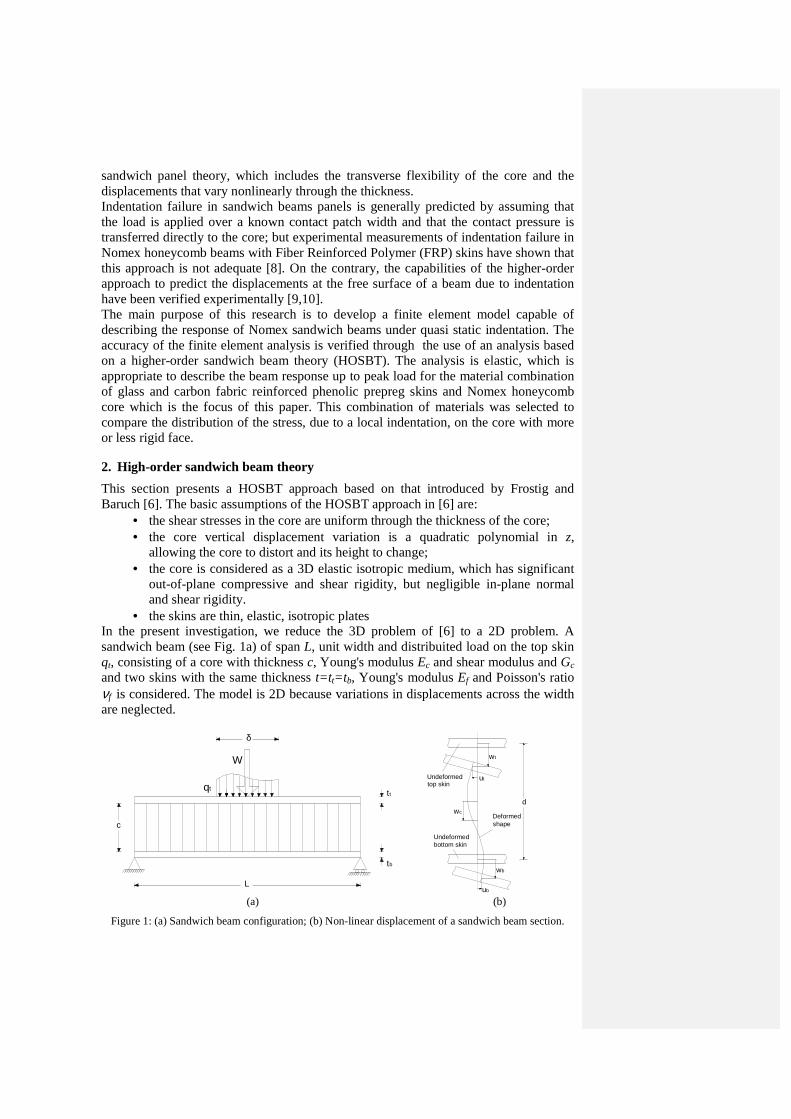
sandwich panel theory, which includes the transverse flexibility of the core and the displacements that vary nonlinearly through the thickness. Indentation failure in sandwich beams panels is generally predicted by assuming that the load is applied over a known contact patch width and that the contact pressure is transferred directly to the core; but experimental measurements of indentation failure in Nomex honeycomb beams with Fiber Reinforced Polymer (FRP) skins have shown that this approach is not adequate [8]. On the contrary, the capabilities of the higher-order approach to predict the displacements at the free surface of a beam due to indentation have been verified experimentally [9,10]. The main purpose of this research is to develop a finite element model capable of describing the response of Nomex sandwich beams under quasi static indentation. The accuracy of the finite element analysis is verified through the use of an analysis based on a higher-order sandwich beam theory (HOSBT). The analysis is elastic, which is appropriate to describe the beam response up to peak load for the material combination of glass and carbon fabric reinforced phenolic prepreg skins and Nomex honeycomb core which is the focus of this paper. This combination of materials was selected to compare the distribution of the stress, due to a local indentation, on the core with more or less rigid face.
2. High-order sandwich beam theory
This section presents a HOSBT approach based on that introduced by Frostig and Baruch [6]. The basic assumptions of the HOSBT approach in [6] are:
• the shear stresses in the core are uniform through the thickness of the core; • the core vertical displacement variation is a quadratic polynomial in z,
allowing the core to distort and its height to change; • the core is considered as a 3D elastic isotropic medium, which has significant
out-of-plane compressive and shear rigidity, but negligible in-plane normal and shear rigidity.
• the skins are thin, elastic, isotropic plates In the present investigation, we reduce the 3D problem of [6] to a 2D problem. A sandwich beam (see Fig. 1a) of span L, unit width and distribuited load on the top skin qt, consisting of a core with thickness c, Young's modulus Ec and shear modulus and Gc and two skins with the same thickness t=t t=tb, Young's modulus Ef and Poisson's ratio νf is considered. The model is 2D because variations in displacements across the width are neglected.
δ
W
qt
L
c
tb
tt
dwc
ub
wb
ut
wt
Deformed shape
Undeformed bottom skin
Undeformed top skin
(a) (b)
Figure 1: (a) Sandwich beam configuration; (b) Non-linear displacement of a sandwich beam section.
The skins consist of layered 0/90-type woven composites so that their bending rigidity is related to their in-plane modules Ef by the usual rules for isotropic materials [6]. The displacement and stress of the core are expressed in terms of the in-plane deformations the top and bottom skins in the x-direction ut and ub,respectively, the corresponding vertical displacements wt and wb at the mid-plane of the skins, and of the shear stresses τx in the core. The notation is illustredin Figure 1b. The governing equations given by [6], adapted to a two-dimensional model, are:
are the in-plane and flexural rigidities, respectively, of the skins. For a simply supported sandwich beam, the solution can be expressed as a Fourier series expressing the variation of the relevant variables in the x-direction as:
1
( ) cos ;M
utt m
m
m xu x C
L
π=
=∑ (4)
1
( ) cos ;M
ubb m
m
m xu x C
L
π=
=∑ (5)
1
( ) sin ;M
wtt m
m
m xw x C
L
π=
=∑ (6)
1
( ) sin ;M
wbb m
m
m xw x C
L
π=
=∑ (7)
1
( ) cos ;M
xx m
m
m xx C
Lτ πτ
=
=∑ (8)
where m is an index for wavelength of the Fourier term and M (=3000) is the number of terms in the Fourier series. The Fourier coefficients Ci
m are constants to be determined. It is assumed that the external load is applied only on the top skin. In this way it can be set it in terms of the Fourier series:
1
( ) sin ;M
qtt m
m
m xq x C
L
π=
=∑ (9)
where Cqtm is a constant that depends on the distribution of the external load. To
simplify calculations, the indentation line load, W, is assumed to be applied to the beam uniformly. This assumption is appropriate for sandwich panels typically used in industry, as discussed in detail by Patras and Sutcliffe [10]. So, the Fourier coefficient Cqt
m is given by:
4sin sin .
2 2qtm
W m mC
m L
π πδπδ
=
(10)
After substituting every term of the Fourier series, Eqs. (4-8) into the governing Eqs. (1), the problem can be expressed in matrix form as:
[ ] [ ] [ ]H C Q⋅ = (11)
where:
[ ]
2
2
4
4
23
0 0 0 1
0 0 0 1
0 02
0 02
1 12 2 12
t
b
c ct
c cc
c c
mA
L
mA
L
E Em c t mH D
L c c L
E Em c t mD
c L c L
c t m c t m c c m
L L G E L
π
π
π π
π π
π π π
−
− −
+ = − + −
+ − − +
+ + − − − +
(12)
utmubmwtmwbm
xm
C
C
C C
C
Cτ
=
and
0
0
0
0
qtm
Q C
=
(13)
Solving Eq. (11) for C, we have:
[ ] [ ][ ] ( ) ( )
( ) ( )
1 2
1 2
1 1
1 2
2
1 2
1 2
t
tutmubm
qtwtmm
f fwbm
xm
f f
f t
C
C
C Q H CC
C
Cτ
−
− +
+ = ⇒ =
− + − − +
+
(14)
where:
( ) ( )( ) ( )
2
4
23
2
1
2
2
,
,
,2
,12
2 ,
2 ,
f t
cf t
cc t
cc c
f f c f t
c f c f t
mA
L
EmD
L c
E c t mand
c L
c c m
G E L
π
π
π
π
= −
= − +
+ = − =
Ω = + = Ω − + = Ω − +
(15)
In this way, all the in-plane and out-of-plane displacements and the core shear stresses can be calculated. The in-plane normal stresses in the top skin, σtxx, and out-of-plane normal stresses in the top skin-core interface, σzz, can be calculated indirectly as:
;ttxx f
uE
xσ ∂
=∂
(16)
( );2
x czz b t
Ecw w
x c
τσ ∂= + −
∂ (17)
Substituting Eqs. (6-8) and the above Fourier coefficients into (17), the normal stresses in the top skin-core interface are given as:
( )1 1 1 2
sin sin2 2
M Mf tx wb wt qtc c
zz m m m mm m f c
Ec mx m x cmx m xC C C C
L c L L Lτ π πσ
= =
= − + − = − + + − ∑ ∑
(18)
Equation (18) shows that the Fourier coefficients for the stress σzz at the skin-core interface can be separated into two parts: the first part consists of the coefficient Cqt
m, which depends only on the distribution of the load; the second part represents the “transmission coefficient”[10] Cσzz
m that depends on the geometric and materials properties of the sandwich beam and on the semi-wavelength of the mth term of the Fourier series. The equations described in this section are implemented using the Matlab programming language to calculate the beam response. Moreover the vertical displacement of the core is derived by [8]:
( ) ( )2
,2
xc b t t
c
z cz zw x z w w w
x E c
τ∂ − += − + − +∂
(19)
3. Material and geometric properties
In this section the materials of the considered sandwich structures considered in this paper are discussed. The core is made of aramid fiber reinforced phenolic honeycomb (Nomex); while the face sheets are made of either carbon or glass 0/90 woven fiber reinforced phenolic prepreg. The sSelected materials are usually chosen in transportation applications for their fire resistance. A mechanical characterization activity was carried out for the face sheet materials to asses the mechanical properties of the skin for which there is a lack of reliable data.The experiments involved tensile tests to evaluate the in-plane tensile and shear properties. Static tensile tests (Fig. 2a) were run on 1x15x250 mm and 1x25x250 coupons for glass and carbon prepreg respectively, tested in one series with the warp fibers parallel to the load and in a second series with warp fibers perpendicular to the load. These tests were performed in accordance with the ASTM D3039M standard [11].
(a) (b)
Figure 2: The testing fixtures used for laminate tests: (a) tensile tests, (b) shear tests.
Static shear tests (Fig. 2b) were run on 2x25x250 mm and 2.5x25x250 tensile coupons for glass and carbon prepreg respectively, with a [+45/-45]2s stacking sequence in accordance with the ASTM D3518M standard [12]. Three strain gauges were applied to each coupon. All tests were run on a 10 kN universal test frame controlled by an electronic control unit which allows monitoring the applied load and the stroke of the top cross head. Strain signals were acquired by a digital data acquisition system. Tests were conducted at a constant cross head velocity of 2 mm/min. Rectangular sandwich beams with dimensions 385x13x50 mm were selected for the analysis. In particular the thickness of the core, c, is 11mm, while for both the families of sandwich beams the face sheets have the same thickness t=1mm manufactured from [0/90]s and [0/90/0/90/0] stacking sequence for glass and carbon prepreg respectively. Table 1 shows the mechanical properties of materials used both in analytical and numerical analysis. The values of the Nomex materials are taken from the Hexcel datasheet [13], while the skin values are derived by classical lamination theory.
Table 1:Mechanical Properties of sandwich constituents.
4. Finite element modelling of indentation behaviour
The purpose of the finite element analysis was to predict the indentation behaviour of honeycomb core sandwich composite beams. The numerical simulations were carried out by using a 2D computational model. The length of the beam was reduced to the half of the that considered in analytical model. The modelling was performed using the
Formaterat: Teckensnitt:11 pt, Fet
Formaterat: Teckensnitt:11 pt, Fet
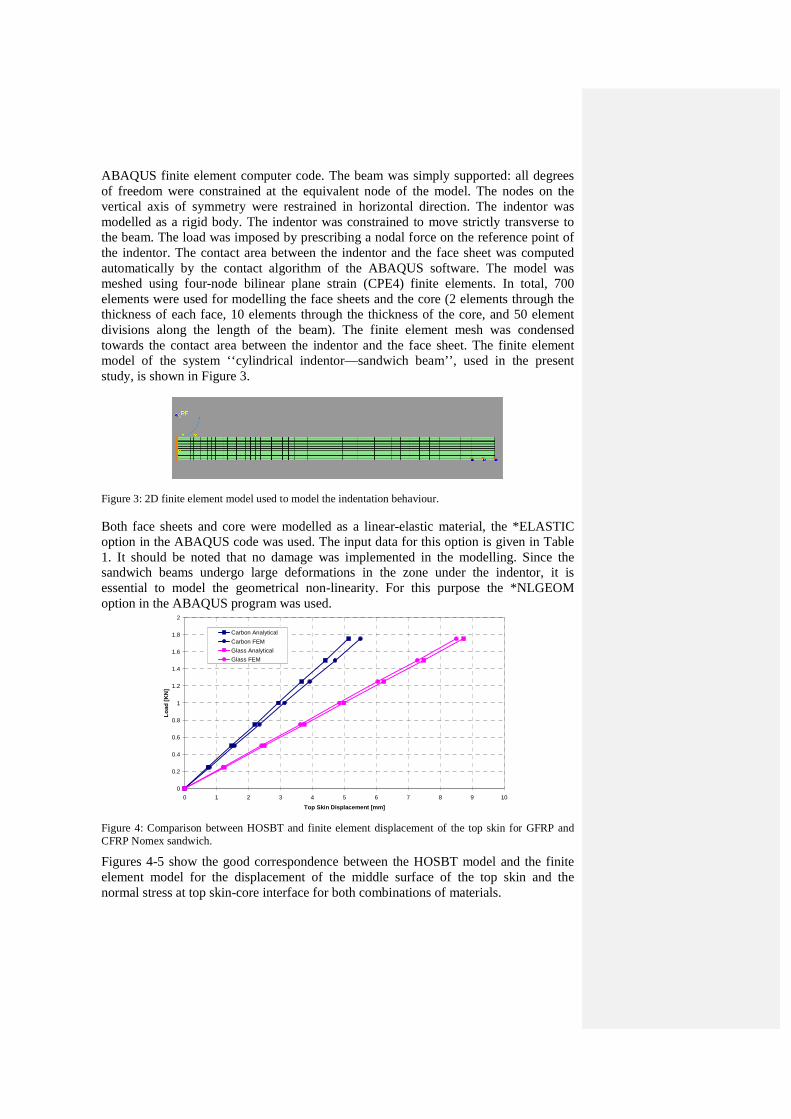
ABAQUS finite element computer code. The beam was simply supported: all degrees of freedom were constrained at the equivalent node of the model. The nodes on the vertical axis of symmetry were restrained in horizontal direction. The indentor was modelled as a rigid body. The indentor was constrained to move strictly transverse to the beam. The load was imposed by prescribing a nodal force on the reference point of the indentor. The contact area between the indentor and the face sheet was computed automatically by the contact algorithm of the ABAQUS software. The model was meshed using four-node bilinear plane strain (CPE4) finite elements. In total, 700 elements were used for modelling the face sheets and the core (2 elements through the thickness of each face, 10 elements through the thickness of the core, and 50 element divisions along the length of the beam). The finite element mesh was condensed towards the contact area between the indentor and the face sheet. The finite element model of the system ‘‘cylindrical indentor—sandwich beam’’, used in the present study, is shown in Figure 3.
Figure 3: 2D finite element model used to model the indentation behaviour.
Both face sheets and core were modelled as a linear-elastic material, the *ELASTIC option in the ABAQUS code was used. The input data for this option is given in Table 1. It should be noted that no damage was implemented in the modelling. Since the sandwich beams undergo large deformations in the zone under the indentor, it is essential to model the geometrical non-linearity. For this purpose the *NLGEOM option in the ABAQUS program was used.
0
0.2
0.4
0.6
0.8
1
1.2
1.4
1.6
1.8
2
0 1 2 3 4 5 6 7 8 9 10
Top Skin Displacement [mm]
Lo
ad [
KN
]
Carbon Analytical
Carbon FEM
Glass Analytical
Glass FEM
Figure 4: Comparison between HOSBT and finite element displacement of the top skin for GFRP and CFRP Nomex sandwich.
Figures 4-5 show the good correspondence between the HOSBT model and the finite element model for the displacement of the middle surface of the top skin and the normal stress at top skin-core interface for both combinations of materials.
0.0
0.5
1.0
1.5
2.0
2.5
3.0
0 1 2 3 4 5 6 7 8
Top Skin Displacement [mm]
No
rmal
Str
ess
[MP
a]
Carbon AnalyticalCarbon FEMGlass AnalyticalGlass FEM
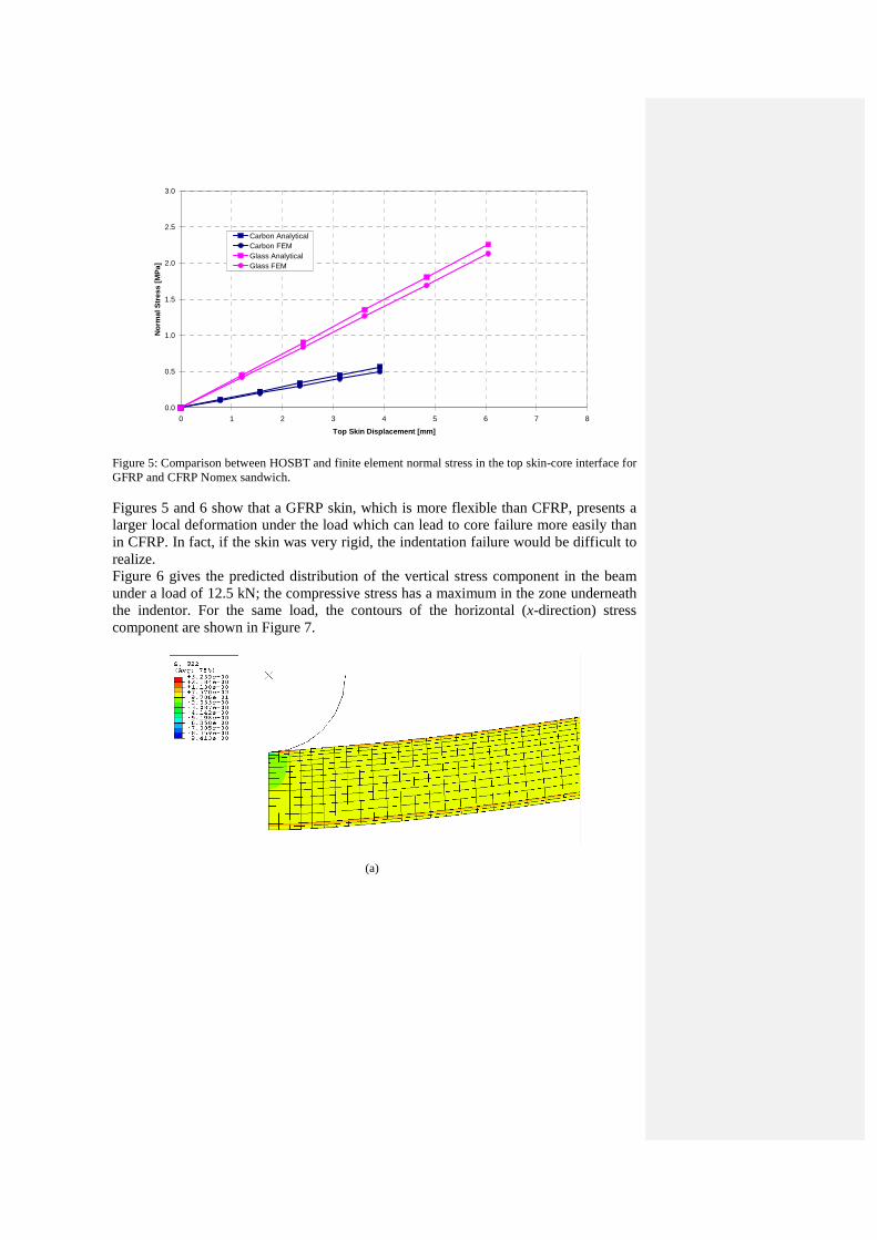
Figure 5: Comparison between HOSBT and finite element normal stress in the top skin-core interface for GFRP and CFRP Nomex sandwich.
Figures 5 and 6 show that a GFRP skin, which is more flexible than CFRP, presents a larger local deformation under the load which can lead to core failure more easily than in CFRP. In fact, if the skin was very rigid, the indentation failure would be difficult to realize. Figure 6 gives the predicted distribution of the vertical stress component in the beam under a load of 12.5 kN; the compressive stress has a maximum in the zone underneath the indentor. For the same load, the contours of the horizontal (x-direction) stress component are shown in Figure 7.
(a)
(b)
Figure 6: Distribution of the vertical stress deduced from the simulation for GFRP (a) and CFRP (b) Nomex sandwich beam.
5. Conclusion
The objective of the work presented in this paper was to develop a 2D finite element modeling procedure for analyzing the indentation behaviour of Nomex cored sandwich composite beams. For this purpose, the ABAQUS finite element package was used. The core and the skins were modeled as linear-elastic materials. The large deformations induced in the case of localized loading were also taken into account in the modeling. In order to validate the numerical model, analytical solutions based on HOSBT were derived. The good agreement between the analytical data and the numerical analysis shows that the finite element modeling can be used to predict the static indentation response of Nomex cored sandwich beams in the linear range of the materials. Future work will focus on the development and validation of accurate finite models including material nonlinearity and damage that are known to occur under sufficiently large indentation forces.
(a)
(b)
Figure 7: Contours of the horizontal stress deduced from the numerical modelling for GFRP (a) and CFRP (b) Nomex sandwich beam.
Acknowledgements
The activities presented in the paper have been conducted within a project in collaboration between the Department of Structural Engineering at University of Naples Federico II and Firema Trasporti whose financial support is kindly acknowledged.
References
1. Allen H. “Analysis and design of structural sandwich panels”. Oxford: Pergamon Press, 1969.
2. Plantema FJ. “Sandwich construction”. New York: Wiley, 1966. 3. Zenkert D., Shipsha A., Persson K. “Static indentation and unloading response of
sandwich beams” . Composites, Part B 35,pp 511-522,2004. 4. Abrate S. “Impact on composite structures”. Cambridge: Cambridge University
Press, 1998. 5. Frosting Y., Baruch M. “Bending of sandwich panels with transversely flexible
core”. AIAA Journal, 28, pp 523-531, 1990. 6. Frosting Y., Baruch M. “Localized load effects in high-order bending of
sandwich panels with flexible core”. Journal of Engineering Mechanics, 122, pp 1069-1076, 1996.
7. Frosting Y., Baruch M. “High-order theory for sandwich-beam behaviour with transversely flexible core”. Journal of Engineering Mechanics, 118, pp 1026-1043, ASCE 1992.
8. Patras A., Sutcliffe MPF. “Failure mode maps for honeycomb sandwich panels”. Composite Structures, 37, 97-108, 1997.
9. Patras A. and Sutcliffe MPF. “Indentation failure analysis of sandwich beams”. Composite Structures, 50, pp 311-318, 2000.
10. Patras A. and Sutcliffe MPF. “Indentation resistance of sandwich beams”. Composite Structures, 46, pp 413-424, 1999.