Motivation Numerical Modeling Numerical Examples and Remarks Appendix The University of Texas at Austin Numerical Modeling of Seabed Gouging by Ice Masses and soil-pipe interaction Hossein Fadaifard, MSc John Tassoulas, Ph.D. Department of Civil, Architectural, and Environmental Engineering The University of Texas at Austin February 14, 2013 BSEE Seabed Gouging 1 / 21
Transcript
MotivationNumerical Modeling
Numerical Examples and RemarksAppendix
The University of Texas at Austin
Numerical Modeling of Seabed Gouging by IceMasses
and soil-pipe interaction
Hossein Fadaifard, MSc John Tassoulas, Ph.D.
Department of Civil, Architectural, and Environmental EngineeringThe University of Texas at Austin
Distance from center of ridge to center of pipe (m)
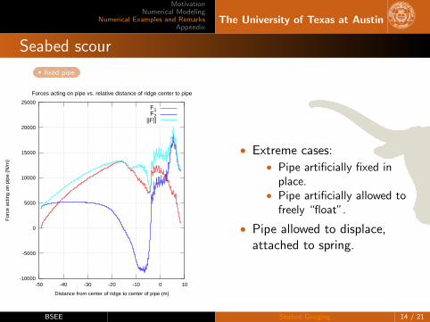
Forces acting on pipe vs. relative distance of ridge center to pipe
F1F2
||F||
• Extreme cases:• Pipe artificially fixed in
place.• Pipe artificially allowed to
freely “float”.
• Pipe allowed to displace,attached to spring.
BSEE Seabed Gouging 14 / 21
MotivationNumerical Modeling
Numerical Examples and RemarksAppendix
The University of Texas at Austin
Seabed scour – “floating” pipe
floating pipe
-0.5
0
0.5
1
1.5
2
2.5
-50 -48 -46 -44 -42 -40
For
ce a
ctin
g on
pip
e (N
/m)
Distance from center of ridge to center of pipe (m)
Forces acting on pipe vs. relative distance of ridge center to pipe
F1F2
||F||
-0.1
0
0.1
0.2
0.3
0.4
0.5
0.6
0.7
-50 -48 -46 -44 -42 -40
Def
lect
ion
of p
ipe
(m)
Distance from center of ridge to center of pipe (m)
Pipe deflection vs. relative distance of ridge center to pipe
∆ x1∆ x2
BSEE Seabed Gouging 15 / 21
MotivationNumerical Modeling
Numerical Examples and RemarksAppendix
The University of Texas at Austin
Seabed scour – Pipe with artificial spring
Pipe with spring
-10000
-5000
0
5000
10000
15000
20000
-50 -40 -30 -20 -10 0 10 20
For
ce a
ctin
g on
pip
e (N
/m)
Distance from center of ridge to center of pipe (m)
Forces acting on pipe vs. relative distance of ridge center to pipe
F1F2
||F||
-0.01
-0.005
0
0.005
0.01
0.015
0.02
-50 -40 -30 -20 -10 0 10 20
Def
lect
ion
of p
ipe
(m)
Distance from center of ridge to center of pipe (m)
Pipe deflection vs. relative distance of ridge center to pipe
∆ x1∆ x2
BSEE Seabed Gouging 16 / 21
MotivationNumerical Modeling
Numerical Examples and RemarksAppendix
The University of Texas at Austin
3-dimensional Scour (without pipe)
3d Scour
BSEE Seabed Gouging 17 / 21
MotivationNumerical Modeling
Numerical Examples and RemarksAppendix
The University of Texas at Austin
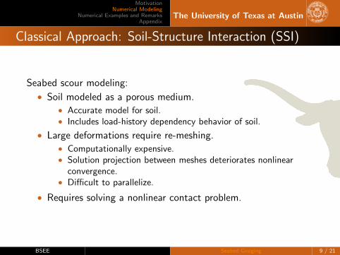
Concluding Comments
• Approximating soil behavior using Herschel-Bulkley modelpromising.
• Problem is very computationally demanding.• ∼ 36 hr for a typical 2D run on a single core.• Projected run time of 5-10 days for 3D analysis on TACC (16
cores).
• Currently working on parametric studies.
BSEE Seabed Gouging 18 / 21
MotivationNumerical Modeling
Numerical Examples and RemarksAppendix
The University of Texas at Austin
Sources I
D. L. Gautier, K. J. Bird, R. R. Charpentier, A. Grantz, D. W. Houseknecht,T. R. Klett, J. K. Moore, T. E.and Pitman, C. J. Schenk, J. H. Schuenemeyer,K. Sorensen, M. E. Tennyson, Z. C. Valin, and C. J. Wandrey.Assessment of undiscovered oil and gas in the arctic.Science, 324:1175 – 1179, 2009.
Arnaud Hequette, Marc Desrosiers, and Peter W. Barnes.Sea ice scouring on the inner shelf of the southeastern canadian beaufort sea.Marine Geology, 128(3-4):201 – 219, 1995.
Tony King, Ryan Phillips, John Barrett, and Gary Sonnichsen.Probabilistic pipeline burial analysis for protection against ice scour.Cold Regions Science and Technology, 59(1):58 – 64, 2009.
P. Wadhams.Ice in the Ocean.CRC PressINC, 2000.
BSEE Seabed Gouging 19 / 21
MotivationNumerical Modeling
Numerical Examples and RemarksAppendix
The University of Texas at Austin
Application: Ridge scour
Table 1: Properties used for preliminary runs of ridge scour