Numerical Study of Masonry Walls Retrofitted by CFRP under Monotonic and Cyclic Loading *Mehdi Ebadijamkhaneh 1) and Mohammad Ali Kafi 2) 1), 2) Faculty of Civil Engineering, Semnan University, Semnan, Iran 1) [email protected]ABSTRACT Some factors such as poor quality of materials, lack of integrity in walls, lack of appropriate foundation, non-suitable horizontal and vertical bracing, having heavy roof in building, existence excessive openings in walls and etc. will cause the destruction of masonry structures against lateral loads. So after destructive earthquakes occur in different parts the world, researchers began to think of ways to retrofit these structures. In recent years use of fiber reinforced polymers (FRP) has been considered as a proper solution to improve the behavior of the lateral resistance and maintain stability system of masonry buildings and several factors affect the quality of this type of retrofitting. This paper is based on numerical modeling using finite element to investigate the effect of polymer fiber on the behavior of masonry walls and their productivity. Meanwhile masonry walls were retrofitted by using three different configurations and at the end force - displacement curves presented and compared with each other. Keywords: masonry building, retrofitting, FRP, numerical modeling, force – displacement curve 1. Introduction In the most of masonry buildings is not used from any of metal or concrete bracing against lateral loads during the earthquake. Masonry buildings are vulnerable because of low strength and brittleness walls against earthquakes. The high vulnerability of these structures is due to the unfavorable combination of mechanical properties. Masonry walls are very heavy and have very little tensile strength. Since the compressive strength of masonry is much greater than the tensile strength, more significant cracks occur in the tensile zone. Destruction and re-building of these structures is not an economic solution, but the behavior of these structures and their improvement techniques is the way should be plan for it. Extent of performed research in the field of masonry buildings is not such as steel or concrete materials because of obsolescence and lacks of consumption in most countries in the world. However, in recent decades, experimental and numerical studies have been carried out on masonry buildings. Benedetti and colleagues carried out 119 shaking table tests on 24 models from two-story houses. They concluded by means of simple techniques such as filling
Transcript
Numerical Study of Masonry Walls Retrofitted by CFRP under Monotonic and Cyclic Loading
Some factors such as poor quality of materials, lack of integrity in walls, lack of
appropriate foundation, non-suitable horizontal and vertical bracing, having heavy roof in building, existence excessive openings in walls and etc. will cause the destruction of masonry structures against lateral loads. So after destructive earthquakes occur in different parts the world, researchers began to think of ways to retrofit these structures. In recent years use of fiber reinforced polymers (FRP) has been considered as a proper solution to improve the behavior of the lateral resistance and maintain stability system of masonry buildings and several factors affect the quality of this type of retrofitting. This paper is based on numerical modeling using finite element to investigate the effect of polymer fiber on the behavior of masonry walls and their productivity. Meanwhile masonry walls were retrofitted by using three different configurations and at the end force - displacement curves presented and compared with each other. Keywords: masonry building, retrofitting, FRP, numerical modeling, force – displacement curve 1. Introduction
In the most of masonry buildings is not used from any of metal or concrete bracing against lateral loads during the earthquake. Masonry buildings are vulnerable because of low strength and brittleness walls against earthquakes. The high vulnerability of these structures is due to the unfavorable combination of mechanical properties. Masonry walls are very heavy and have very little tensile strength. Since the compressive strength of masonry is much greater than the tensile strength, more significant cracks occur in the tensile zone. Destruction and re-building of these structures is not an economic solution, but the behavior of these structures and their improvement techniques is the way should be plan for it.
Extent of performed research in the field of masonry buildings is not such as steel or concrete materials because of obsolescence and lacks of consumption in most countries in the world. However, in recent decades, experimental and numerical studies have been carried out on masonry buildings.
Benedetti and colleagues carried out 119 shaking table tests on 24 models from two-story houses. They concluded by means of simple techniques such as filling
existing cracks in walls or horizontal metal strips the building performance can be improved in lateral excitation.
Corradi et al. studied the proposed system retrofitted by diametric compression tests. This system included scraping strips inside the wall and fills them with proper mortar. They conclude that this method can increase the stiffness of the shear the wall up to three times.
Ghobarah and Galal carried out experiments on five full-scale model brick wall. Out of plane loading was applied cyclic to walls. The walls were reinforced with horizontal and vertical FRP strips. Their retrofitting system provides a frame of FRP around the openings and Increase the strength and ductility of walls to 3 and 10 times, respectively.
Sathipran and colleagues carried out diametric compression test on masonry samples that were retrofitted with polypropylene mesh. They concluded that the system can increase the In-plane strength and ductility of the masonry walls to 2.5 and 45times, respectively. Yi and et al studied the three-dimensional finite element model of integrated elastic and non-integrated inelastic and they concluded non-integrated inelastic models are unable to model the behavior rocking and sliding of masonry parts, that considers as a most important failure modes.
Watanabe and Cao proposed a method for the analysis of masonry structures where the non-isotropic hyperbolic equations used to describe the properties of the blocks and and was used to model the behavior of the mortar between the blocks by viscoelastic element link. Numerical model also discussed to analysis of a retrofitting masonry building with wooden frames. Since the test is very expensive and time consuming therefore, by numerical studies and calibration the input parameters of the numerical model, we obtain a model that can evaluate Seismic Retrofitting of other structures. In coming study will examine the effects of different arrangements of polymer fibers on shear strength and energy absorption in the unreinforced masonry walls by using numerical methods. 2. Numerical modeling 2.1. Geometric and mechanical properties of materials
Walls used in this analysis have the dimensions 100 * 100 * 20 cm made of blocks with dimensions 20 * 20 * 10 cm. The arrangement of the blocks together such a way that vertical seams and gaps between the straight top and bottom rows are not in one direction and somehow create a continuous wall. Static and cyclic loading has been carried out in this study. So must use a suitable behavior model for masonry blocks to give an appropriate response both in compression and in tension under cyclic load. Therefore concrete damage plasticity model is used for modeling of brick material. CFRP fibers with a width of 10 cm were used for the retrofitting. Characteristics of the used materials are shown in tables 1 to 4.
Table 1 – Characteristics of polymer fibers
Characteristics of polymer fibers
230000 Tensile modulus of elasticity (MPa)
0.3 Poisson’s ratio
0.13 thickness (mm)
3500 tensile strength (MPa)
1.5 Ultimate tensile strain (%)
Table 2 – Elastic properties of block
Elastic properties of block
3200 modulus of elasticity (MPa)
0.18 Poisson’s ratio
1800 density
Table 3- plastic behavior of block in pressure
Pressure
stress (MPa) Plastic strain
7.26 0
7.03 0.00046
6.58 0.0029
5.90 0.0044
4.83 0.006
3.47 0.008
Table 4- plastic behavior of block in tension
tension
stress (MPa) Plastic strain
4.5 0
0.5 0.001
0.1 0.003
To model the behavior of mortar in normal direction, hard contact behavior and
in tangential case, fixed friction coefficients were used. The friction coefficient to simulate the shear behavior of mortar is considered 0.6 and adhesion value is considered equal to 3.5 kilograms per square centimeter. 2.2. elements used in the numerical model
In this article two different elements for blocks and polymer fibers is used to model the masonry walls. Masonry blocks were mesh with hexagonal solid elements. This is the kind of continuous, three-dimensional element with eight nodes that each node has 3 degrees of freedom along the principal axes and has the ability to accept any type of mass and rotational load as well as linear and planar loads with different
intensity. In this element shape functions derived from reduced integration methods were used for force and displacement distributions and other parameters.
Figure 1 - solid element used for masonry blocks
For meshing FRP strips was used a kind of shell elements. This element is a
three-dimensional element with four nodes and very low thickness that each node has 6 degrees of freedom and has the ability to consider the nonlinear strain. As like as last case, shape functions derived from reduced integration methods were used for force and displacement distribution and other parameters.
Figure 2 - The shell element used for polymer fiber strip
It should be noted that 2000 solid elements and 30 shell elements per unit length
for FRP is used in finite element model mesh. The finite element model can be used to model the contact between the wall members. General contact mode is used to model the contact between the contact surfaces. Figure 3 shows the finite element model without fiber.
Figure 3 - Finite element model of masonry wall without fiber 2.3. loading conditions and fiber configuration
In this article the rigid beam on top of wall with the dimensions 100 * 20 * 20 cm was used to apply vertical and lateral loads. Initially, vertical compressive load of 12 kg/ cm2 was applied gradually and then proportional lateral displacements were applied to wall. These displacements were considered in monotonic state to increase linearly up to 3 cm and in cyclic mode with maximum amplitude of 2 cm (Fig. 4). Also, pressure load on the wall is considered in order to simulate the ceiling’s effect and modeling conditions closer to the actual situation. The fibers with a width of 10 cm used for reinforcement in different arrangement on the wall. In the first case fibers was used in the form of X, in the second case, the frame around the wall and in third case overall on the outer surface of the wall were used. This action has been done only on the one outer surface of the wall. Finally, the results of the force - displacement graphs are compared with each other.
Figure 4 - Lateral displacement variation with time in cyclic loading
-2
-1.5
-1
-0.5
0
0.5
1
1.5
2
0 2 4 6 8 10 12 14 16 18 20
late
ral d
isp
lace
men
t(cm
)
time(s)
3. Results 3.1. Validation
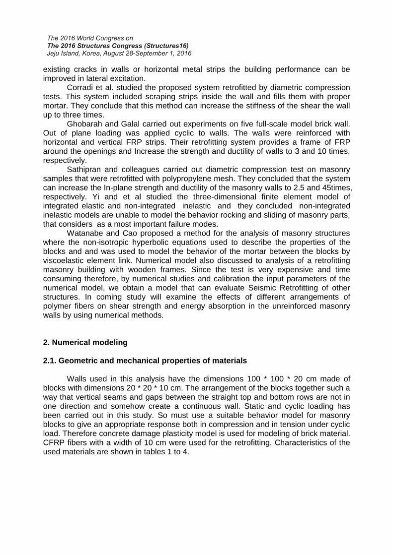
Mr. Daniel Oliveira tested the experimental model that included Walls of the scale of 1*1 meter and 20 centimeters thick. The dimensions of the blocks used in Wall is 20 * 20 * 10 cm. First vertical load 100 KN was applied on the wall and then lateral monotonic displacement were applied to wall in second step. Now, the numerical model mentioned above will be discussed and the results compare with the experimental result.
Figure 5 - the numerical model (b) and experimental (a) for wall with vertical 100 KN
load
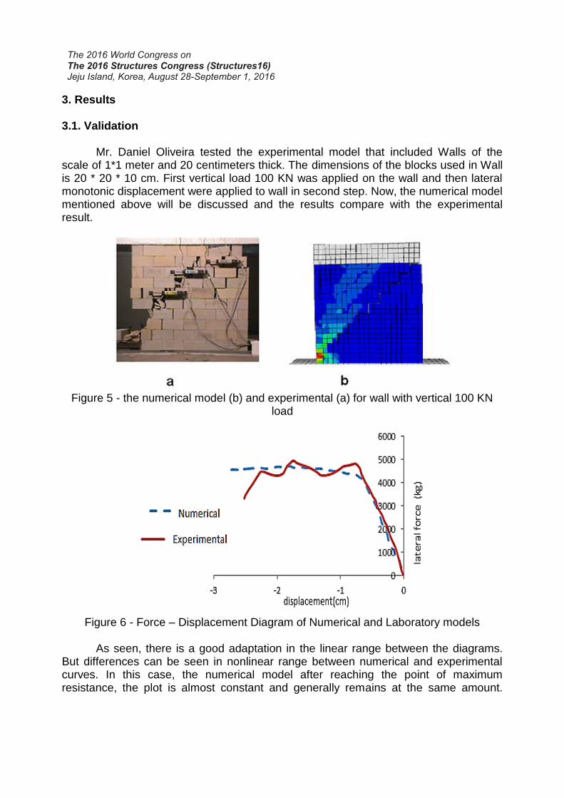
Figure 6 - Force – Displacement Diagram of Numerical and Laboratory models
As seen, there is a good adaptation in the linear range between the diagrams.
But differences can be seen in nonlinear range between numerical and experimental curves. In this case, the numerical model after reaching the point of maximum resistance, the plot is almost constant and generally remains at the same amount.
While in laboratory model diagram, after crossing the linear area, there is a decrease in strength and this strength reduction increased gradually. These changes are not seen in the graph of the numerical model. It can be caused by changes in the characteristics of nonlinear behavior material, the complexity of the interactions between the blocks and nonlinear behavior of the mortar. Overall Due to the low rate differences between numerical and experimental results, the results of modeling can be considered good and sufficient accuracy. 3.2. Results of monotonic case
In Figure 7 all force - displacement curves of numerical models are presented simultaneously. Which it can be paid to the effects on each of the retrofitting methods of fiber to absorb shear force at the base of the wall and compared their impact on the energy absorbing that is related to the area under the curve graphs. Overall it can be said that for this case, the best answer to applied load is for retrofitting with full fiber. Cross form and frame shape retrofitted systems were affective after the first type.
Figure 7 - Force - displacement Graphs of all numerical models
When comparing different states should be noted the area of the wall which is
covered with fibers and is considered their effectiveness. A comparison has been done in Table 5 between the area covered by the fibers and the increase rate of wall shear proportionally with each retrofitting state. Table 5 - Comparison between the fiber surface and increase rate of the shear strength
Retrofitting style Percentage of the surface covered with
FRP fiber
Base shear strength of Walls (ton)
Normal 0 6.8
X-type 25 10.5
Frame type 35 10
Full cover 100 13.4
0
2000
4000
6000
8000
10000
12000
14000
-3 -2.5 -2 -1.5 -1 -0.5 0
forc
e(kg
)
displacement(cm)
Normal
Full cover
X-type cover
Frame type cover
Figure 8 presents a mode of deformation and combination stresses in a masonry wall created by modeling different states of fiber covering.
Figure 8 - Mode of deformation and combination stresses created in wall a - Normal, b – X- coverage, c - covered frame, d - full coverage
3-3 Results of cyclic loading
Hysteresis curve of model without fiber that is a control model is considered in figure 9.
Figure 9 - hysteresis curve of the wall without reinforcement
-8000
-6000
-4000
-2000
0
2000
4000
6000
8000
-2 -1.5 -1 -0.5 0 0.5 1 1.5 2
Hori
zenta
l fo
rce(
kg)
Displacement(cm)
From the above graph we can see that the maximum lateral resistance wall has equal to 7400 kg under cyclic shear load. However, this is 600 kg greater than the maximum tolerated lateral load at monotonic case that represents 10% of increase. Hysteresis curve of model with X-shape fiber is shown in figure 10.
Figure 10 - Hysteresis curve of model with X-shape fiber
As is clear from the above graph, in this case the wall is able to withstand a force
equal to 11400 kg and this amount has been increased 4,000 kg as compared to wall without fibers.
In this case the area under curve in each cycle is greater than normal state. In fact, it can be said that X-shape covering has created a more favorable position with energy dissipation. After cyclic loading was carried out on masonry wall that is reinforced with fibers in the corners. Hysteresis curve retrofitted model with frame shape fibers is shown in Figure 11.
-13000
-8000
-3000
2000
7000
12000
-2 -1.5 -1 -0.5 0 0.5 1 1.5 2
Ho
rize
nta
l F
orc
e(K
g)
Horizental Displacement(cm)
Figure 11 - Hysteresis curve of model with frame-shape fiber
As is clear from the above graph, in frame shape case, the wall is able to
withstand a force equal to 12000 kg and this amount has been increased 7400 kg as compared to wall without fibers that represents an increase of 62 percent. Also it is more than 8 percent of the X-type. While the exterior walls surface were completely covered with polymer fibers. Results were shown in figure 12.
Figure 12 - Hysteresis curve of model with full covering fiber
According to the above curve can be said in this case maximum lateral force is
about 16,000 kg that wall could bear during cyclic loading. In other words, increasing the shear strength in the base of the wall was 115 percent. According to the obtained
-15000
-10000
-5000
0
5000
10000
15000
-2 -1 0 1 2
Ho
rize
nta
l F
orc
e(K
g)
Lateral Displacement(cm)
-18000
-14000
-10000
-6000
-2000
2000
6000
10000
14000
-2 -1.5 -1 -0.5 0 0.5 1 1.5 2
Lat
eral
Forc
e(K
g)
Horizental Displacement(cm)
results is considered as the best response to the other modes. A comparison has been done in Table 6 between the area covered by the fibers and the increase rate of wall shear proportionally with each retrofitting state.
Table 6 - Comparison between the fiber surface and increase rate of the shear strength
Retrofitting style Percentage of the surface covered
with FRP fiber Base shear strength
of Walls (ton)
Normal 0 7.4
X-type 25 11.4
Frame type 35 12
Full cover 100 16
4. Conclusion
In this article the effect of polymer fibers covering with different configurations on the masonry wall examined by using of finite element and numerical methods. In summary, the present results are discussed here:
In monotonic loading, maximum resistance force of the wall in normal mode was about 7000 kg. Resistance increased the 55, 47 and 97% for X- coverage, frame coverage and full coverage respectively. But in terms of efficiency X- case and frame case worked better than full coverage because they were covered by lower surface of fibers. Diagonal and stepped cracks appeared in samples was caused by the weakness of the tensile in mortar and just the size and scope of the cracks changed depending on covering style.
In cyclic loading, maximum base shear force of the wall in normal mode was about 7400 kg. Resistance increased the 54, 62 and 115% for X- coverage, frame coverage and full coverage respectively. However, unlike the monotonic case, frame covering has a little better reistance performance than the resistive X-shape covering.
REFERENCES
Benedetti, D., Carydis, P., and Pezzoli, P., "Shaking table tests on 24 simple masonry buildings", Journal of Earthquake Engineering and Structural Dynamics, Vol. 27, No. 1, pp. 67-90, January 1998.
Corradi M., Tedeschi C., Binda L. , Borri A. (2006) Experimental evaluation of shear and compression strength of masonry wall before and after reinforcement: Deep repointin, Construction and Building Materials
A. Ghobarah and K. El Mandooh Galal, Out-of-Plane Strengthening of Unreinforced Masonry Walls with Openings, Journal of Composites for Construction, Vol. 8, No. 4, August 1, 2004.
N. Shathiparan, P. Mayorca, K.N. Nesheli, R. Guragain, K. Meguro, Experimental study on in-plane and out-of-plane behavior of masonry wallets retrofitted by PP- band meshes.
Yi, T., Moon, F. L., Leon R. T., and Kahn L. F. (2006). “Lateral load tests on a two story unreinforced masonry building.” J. Struct. Eng., 132(5), 643-652.
Zengyan Cao; Hiroyuki Watanabe. (2004). “Earthquake Response Prediction and Retrofitting Techniques of Adobe Structures.” 13thWorld Conference on Earthquake Engineering Vancouver, B.C., Canada, August 1-6, 2004, Paper No. 2594
Oliviera.D,Lourenco.P.B,Experimental and Numercial Analysis of Block Masonry Structures under Cyclic Loading,Ph.D Thesis , University of Minho,Portugal,2003
Hernán Santa Maria1, Pablo Alcaino2, Carl Luders, Experimental Response Of Masonry Walls Externally Reinforcel With Carbon Fiber Fabrics, Proceedings of the 8th U.S. National Conference on Earthquake Engineering ,April 18-22, 2006, San Francisco, California, USA, Paper No. 1402


![CFRP [Wet-preg]](https://static.documents.pub/doc/80x56/546e6828b4af9faa268b4674/cfrp-wet-preg.jpg)

