Instruction BookletPage 2 Effective: April 2017 ATC-300+ Automatic
Transfer Switch Controller
THE ATC-300+ CONTROLLER IS FACTORY PROGRAMMED FOR A SPECIFIC AUTOMATIC TRANSFER SWITCH. DO NOT ATTEMPT TO INTERCHANGE ATC-300+ CONTROL DEVICES WITHOUT CONSULT-ING EATON ELECTRICAL.
All possible contingencies that may arise during installation, oper-ation, or maintenance, and all details and variations of this equip-ment do no purport to be covered by these instructions. If further information is desired by the purchaser regarding a particular installation, operation, or maintenance of particular equipment, please contact an authorized EATON Sales Representative or the installing contractor.
Section 1: Introduction
1.1 Preliminary Comments and Safety PrecautionsThis technical document is intended to cover most aspects asso-ciated with the installation, application, operation, and mainte-nance of the Automatic Transfer Controller (ATC)-300 Controller. It is provided as a guide for authorized and qualified personnel only in the selection and application of the ATC-300+ Controller. Please refer to the specific WARNING and CAUTION in Section 1.1.2 before proceeding. If further information is required by the purchaser regarding a particular installation, application, or main-tenance activity, please contact an authorized EATON sales rep-resentative or the installing contractor.
1.1.1 Warranty and Liability InformationNo warranties, expressed or implied, including warranties of fit-ness for a particular purpose of merchantability, or warranties arising from course of dealing or usage of trade, are made regard-ing the information, recommendations and descriptions contained herein. In no event will EATON be responsible to the purchaser or user in contract, in tort (including negligence), strict liability or otherwise for any special, indirect, incidental or consequential damage or loss whatsoever, including but not limited to damage or loss of use of equipment, plant or power system, cost of capi-tal, loss of power, additional expenses in the use of existing power facilities, or claims against the purchaser or user by its customers resulting from the use of the information and descrip-tions contained herein.
1.1.2 Safety PrecautionsAll safety codes, safety standards, and/or regulations must be strictly observed in the installation, operation, and maintenance of this device.
THE WARNINGS AND CAUTIONS INCLUDED AS PART OF THE PRO-CEDURAL STEPS IN THIS DOCUMENT ARE FOR PERSONNEL SAFETY AND PROTECTION OF EQUIPMENT FROM DAMAGE. AN EXAMPLE OF A TYPICAL WARNING LABEL HEADING IS SHOWN ABOVE TO FAMILIARIZE PERSONNEL WITH THE STYLE OF PRESENTATION. THIS WILL HELP TO INSURE THAT PERSONNEL ARE ALERT TO WARNINGS, WHICH APPEAR THROUGHOUT THE DOCUMENT. IN ADDITION, WARNINGS AND CAUTIONS ARE ALL UPPER CASE AND BOLDFACE.
COMPLETELY READ AND UNDERSTAND THE MATERIAL PRESENTED IN THIS DOCUMENT BEFORE ATTEMPTING INSTALLATION, OPERA-TION, OR APPLICATION OF THE EQUIPMENT. IN ADDITION, ONLY QUALIFIED PERSONS SHOULD BE PERMITTED TO PERFORM ANY WORK ASSOCIATED WITH THIS EQUIPMENT. ANY WIRING INSTRUCTIONS PRESENTED IN THIS DOCUMENT MUST BE FOL-LOWED PRECISELY. FAILURE TO DO SO COULD CAUSE PERMANENT EQUIPMENT DAMAGE.
1.2 BackgroundTransfer switches are used to protect critical electrical loads against loss of power. The load’s Source 1 power source is backed up by a Source 2 power source. A transfer switch is con-nected to both the Source 1 and Source 2 power sources and supplies the load with power from one of the two sources. In the event that power is lost from Source 1, the transfer switch trans-fers the load to the Source 2 power source. This transfer can be automatic or manual, depending upon the type of transfer switch equipment being used. Once Source 1 power is restored, the load is automatically or manually transferred back to the Source 1 power source, again depending upon the type of transfer equip-ment being used.
In automatic transfer switch (ATS) equipment, the switch’s intel-ligence system initiates the transfer when the Source 1 power falls below or rises above a preset voltage or frequency. If the Source 2 power source is a standby generator, the ATS initiates generator start up then transfers to the Source 2 power source when sufficient generator voltage is available. When Source 1 power is restored, the ATS automatically transfers back to the Source 1 power source and initiates generator engine shutdown.
An ATS consist of three basic elements:
1. Main contacts to connect and disconnect the load to and from the power sources.
2. A mechanism to transfer the main contacts from source to source.
3. Intelligence/supervisory circuits to constantly monitor the condition of the power sources and thus provide the intelli-gence necessary for the switch and related circuit operation.
This manual deals with the third basic element of the ATS, the required intelligence/supervisory circuits. Earlier ATSs were con-trolled by relay logic type or a solid-state, single board controllers. In either case, the control panel consisted of a number of individ-ually mounted and wired devices offering a limited amount of sys-tem flexibility, especially in the case of the relay logic design. The ATC-300+ Controller advances the application of intelli-gence, supervisory, and programming capabilities for ATS equip-ment. The Eaton controllers are continuing to be enhanced, mainly through firmware for present real world applications. The smartEST (smart Eaton Switch Technology) brings a new stan-dard in Automatic Transfer Switches. Appendix C shows the controller's recent enhancements.
1.3 Product OverviewThe ATC-300+ Controller is a comprehensive, multi-function, microprocessor based ATS controller. It is a compact, self-con-tained, panel mounted device designed to replace traditional relay and solid-state logic panels.
CAUTION
WARNING
CAUTION
For more information visit: www.eaton.com IB01602009E
Instruction BookletEffective: April 2017 Page 3ATC-300+ Automatic
Transfer Switch Controller
Designed to meet the needs of markets worldwide, the ATC-300+ Controller:
• Is a UL Recognized Component• Complies with UL 1008/ CSA 22.2-178• Meets the Intent of UL 991• Meets IEC 1000-4-2, 1000-4-3, 1000-4-4, 1000-4-5, 1000-4-
6, and 1000-4-11• Meets CISPR 11, Class A• Complies with FCC Part 15, Class A• Meets European Standards Conformance (CE mark)The ATC-300+ Controller provides an unmatched degree of pro-grammed flexibility to address the needs of any system. It oper-ates from all system voltages between 120 and 600 Vac, single-phase and 3-phase, at 50 or 60 Hz. In addition, a period of no control power operation is provided. The ATC-300+ Controller monitors the condition of the 3-phase line-to-line voltage and fre-quency of both the Source 1 and Source 2 power sources. It can also be programmed for single-phase operation. The ATC-300+ Controller provides the necessary intelligence to insure that the switch operates properly through a series of programmed sensing and timing functions.
A standard ATC-300+ Controller will:
• Monitor Source 1 and Source 2 power source voltages and fre-quencies;
• Provide undervoltage monitoring of the Source 1 and Source 2 power sources;
• Permit customer programming;• Display real-time and historical information;• Permit system testing;• Store customer/factory established parameters in nonvolatile
memory; and• Provide faceplate source status indications.
1.4 GlossaryWith respect to their use within this document and as they relate to ATS and controller operation, the following terminology is defined.
AvailableA source is defined as “available” when it is within its undervolt-age/overvoltage/ underfrequency/overfrequency (if applicable) setpoint ranges for the nominal voltage and frequency setting.
ConnectedConnected is defined as when the input is shorted by an external contact or connection.
Failed or FailsA source is defined as “failed” when it is outside of the applicable voltage and frequency setpoint ranges for the nominal voltage and frequency setting for a time exceeding 0.5 seconds after the time delay emergency fail (TDEF) time delays expires.
FailsafeFailsafe is a feature that prevents disconnection from the only available power source and also forces a transfer or re-transfer operation to the only available power source.
Note: The ATC-300+ controller is a newer version of the ATC-300.
Re-TransferRe-transfer is defined as a change of the load connection from the Source 2 to the Source 1.
Source 1Source 1 is the primary source (normal source, normal power source, or normal).
Source 2Source 2 is the secondary source (emergency source, emergency power source, emergency, standby, or backup source).
Source 1: Failed or FailsSource 1 is defined as “failed” when it is outside of its undervolt-age/overvoltage/ underfrequency/overfrequency (if applicable) setpoint ranges for the nominal voltage and frequency setting.
Source 2: Failed or FailsSource 2 is defined as “failed” when it is outside of its undervolt-age/overvoltage/ underfrequency/overfrequency (if applicable) setpoint ranges for the nominal voltage and frequency setting for a time exceeding 0.5 seconds after the TDEF time delay expires.
TransferTransfer is defined as a change of the load connection from the Source 1 to the Source 2 power source, except when specifically used as “Transfer to Neutral”.
Transfer to NeutralTransfer to neutral is defined as when the load circuits are dis-connect from both the Source 1 and Source 2 power sources.
UnconnectedUnconnected is defined as when the input is not shorted by an external contact or connection.
VIN, RMSRefers to the operating input voltage (Vac, RMS).
1.5 Functions/Features/OptionsThe primary function of ATC-300+ Controller is to accurately monitor power sources and provide the necessary intelligence to operate an ATS in an appropriate and timely manner. In addition, the ATC-300+ Controller provides programming through the device’s faceplate or communication option.
1.5.1 Operational SimplicityFrom installation to programming to usage, the ATC-300+ Con-troller was designed with operational simplicity in mind. Only one style needs to be considered, regardless of input/output require-ments or system voltages and frequencies. The ATC-300+ Con-troller provides the functionality of numerous other devices combined in one package that mounts in 6.5 by 8.5 inches of panel space.
The user-friendly front panel interface simplifies routine opera-tion, programming, data presentation, and setting adjustments. An LCD-based display provides the flexibility of a back-lit display for enhanced visibility. The operation of the front panel mem-brane pushbuttons move the ATC-300+ Controller display from function to function or step to step within a function.
IB01602009E For more information visit: www.eaton.com
Instruction BookletPage 4 Effective: April 2017 ATC-300+ Automatic
Transfer Switch Controller
1.5.2 Standard and Optional FeaturesA variety of programmable features are available with the ATC 300 Controller to meet a wide variety of application require-ments. Besides the feature setpoints, their is a setpoint to allow the user to pick what type switch the controller will control; a 2 position contactor, a 3 position contactor, a breaker, a 3K con-tactor, or a Magnum. Everything is present for the user to set.
The features are factory activated, depending upon customer requirements. The specific variable setpoints associated with the features are stored in nonvolatile memory. The setpoints are available for customer adjustment. Some setpoints are not view-able depending on what type of switch it is programmed to. For example, a two position contactor would not have a TDN set-point.
1.5.2.1 Standard FeaturesThe following is a list of some of the standard features of the ATC-300 Controller.
1. Time Delay Normal to Emergency (TDNE)
This feature provides a time delay when transferring from the Source 1 to the Source 2 power source. Timing begins when Source 2 becomes available. It permits controlled transfer of the load circuit to Source 2.
Adjustable 0 - 1800 Seconds
2. Time Delay on Engine Starting (TDES)
This feature provides a time delay of the signal to initiate the engine/generator start cycle in order to override momentary power outages or voltage fluctuations of Source 1.
Adjustable 0 - 120 Seconds
3. Time Delay Emergency to Normal (TDEN)
This feature provides a time delay of the re-transfer opera-tion to permit stabilization of Source 1. Timing begins when Source 1 becomes available. If Source 2 fails during timing, then re-transfer is immediate, overriding the time delay.
Adjustable 0 - 1800 Seconds
4. Time Delay for Engine Cool-down (TDEC)
This feature provides a time delay of the signal to initiate the engine/generator stop cycle after the re-transfer operation. This allows the engine/generator to cool down by running unloaded. Timing begins on completion of the re-transfer cycle.
Adjustable 0 - 1800 Seconds
5. Source 2 Monitoring and Protection
This feature provides monitoring and protection based on the Source 2 voltage and/or frequency setpoints. All feature 5 functions are “failsafe” operations.
5H/26H. Phase Reversal Protection
For a 3-phase wye source, this feature monitors the phase sequence of the sources. If a source does not have the same ABC or CBA sequence as the setpoint value, that source will be considered “Unavailable”.
For a 3-phase delta source, this feature should be turned off via the PHASE REV setpoint.
5J/26J. 3-Phase Undervoltage and Underfrequency Protection
Adjustable Undervoltage:Dropout: 70 - 97% of nominal (0=Disabled)Pickup: (Dropout +2%) - 99% of nominal (0=Disabled)
Adjustable Underfrequency:Dropout: 90 - 97% of nominal (0=Disabled)Pickup: (Dropout +1Hz) - 99% of nominal (0=Disabled)
5K/26K. 3-Phase Overvoltage/Overfrequency
Adjustable Overvoltage:Dropout: 105 - 120% of nominal (0=Disabled)Pickup: 103% - (Dropout –2%) of nominal (0=Disabled)
Adjustable Overfrequency:Dropout: 103 - 110% of nominal (0=Disabled)Pickup: 101% - (Dropout -1Hz) of nominal (0=Disabled)
5L/26L. 3-Phase Voltage Unbalance
For a 3-phase wye source, this feature monitors phase volt-age ratios. Voltage unbalance (%) is calculated as the differ-ence between the maximum and minimum phase voltage, divided by the minimum phase voltage. User-selectable set-points are available for dropout and pickup unbalance set-tings (minimum 2% differential). Dropout is adjustable from 5 to 20%. Pickup is adjustable from 3% to (Dropout –2%). A setpoint for user-selectable time delay from 10 to 30 sec-onds is provided. A user-selectable setpoint for enable and disable is provided.
When an unbalance condition is detected on the Source, the Unbalance Timer (TD UNBAL) starts timing. After TD UNBAL times out, Source 2 is declared “failed”.
For a 3-phase delta source, this feature should be turned off via the VOLT UNBAL setpoint.
For more information visit: www.eaton.com IB01602009E
Instruction BookletEffective: April 2017 Page 5ATC-300+ Automatic
Transfer Switch Controller
6. Test Operators
Eaton ATSs are provided with a Test Pushbutton on the front panel of the controller that simulates a loss of the Source 1 power source as standard (Feature 6B). All pro-grammed time delays (TDNE, TDEN, etc.) will be performed as part of the Test. Engine run time of the Test is equal to the Plant Exerciser programmed setpoint. All Tests are Failsafe protected.
6B. Test Pushbutton
Programmable setpoints include:
1. Load, No Load Testing, or Disabled and
2. Engine run time is equal to the Plant Exerciser setting.
7. Time Delay Emergency Fail (TDEF)
This feature provides a time delay that prevents a con-nected emergency source from being declared “failed” in order to override momentary generator fluctuations. If the Source 2 power source remains in the failed state then, 0.5 seconds after the TDEF timer expires, the transfer switch will proceed with the programmed sequence for re-transfer. This time delay is only implemented when the Source 2 power source is a generator.
Adjustable 0 - 6 Seconds
8. Time Delay Bypass Pushbutton
This feature provides a way (by pushing the Help and Step pushbutton simultaneously) to bypass the TDNE (Feature 1) and/or TDEN time delays. The Time Delay Bypass func-tion, when activated by pushing the Help and Step push-button simultaneously, will reduce any or all of the programmed time delay to zero.
8C. Bypass TDEN
This feature provides a membrane pushbutton to bypass the TDEN time delay.
8D. Bypass TDNE
This feature provides a membrane pushbutton to bypass the TDNE time delay.
12. Power Source Annunciation
This feature provides LEDs to give switch position and power source availability indications.
Switch Position
Provides LEDs to indicate the switch position. The auxiliary switches on the switching device are used for the switch position.
12C. Source 1 - Source Connected
This feature provides a green LED that, when lit, indicates the load is connected to Source 1.
12D. Source 2 - Source Connected
This feature provides a red LED that, when lit, indicates the load is connected to Source 2.
Power Source Availability
Provides LEDs to indicate if a power source is available. LEDs may be integral or separate from the controller.
12G. Source 1 - Available
This feature provides a white LED that, when lit, indicates Source 1 is available.
12H. Source 2 - Available
This feature provides an amber LED that, when lit, indi-cates Source 2 is available.
23. Plant Exerciser (PE)
This feature provides a means for automatic testing of the engine/generator set or standby power system. All pro-grammed time delays will be performed during plant exer-ciser operations.
23K. Plant Exerciser Selectable – Disabled/1/7/14/28 Day Inter-val
This feature provides for automatic test operation of the generator. Available test cycles are daily, 7, 14, or 28 days with duration equal to the programmed engine test time.
Programmable setpoints allow for selection of three test cycles:
• Engine Start/Run Only (No Load);• Exercise with Load Transfer; or Disabled• This is a “Failsafe” operation.
26. Source 1 - Monitoring and Protection
This feature provides Source 1 monitoring and protection functions. If the Source 1 power supply fails, then the ATC-300+ will begin the sequence of operations neces-sary to transfer the load circuit to the Source 2 power source. All Feature 26 monitoring and protection func-tions are “failsafe” operations.
26D. Go to Source 2
This feature provides the capability for an external contact opening to initiate a load power transfer to the Source 2 power source. This includes starting the engine/generator, performing the programmed time delays, and the transfer operation. Re-transfer will occur when the external con-tact is closed or under a “failsafe” condition. A connection point on the controller for the connection of an external contact is included.
See Table 2 in section 6.5 for all the setpoints in order for the ATC-300.
IB01602009E For more information visit: www.eaton.com
Instruction BookletPage 6 Effective: April 2017 ATC-300+ Automatic
Transfer Switch Controller
29. Alternate Transfer Modes of Operation
Provides standard or optional transfer modes, mode selec-tion devices, and operational methods for ATSs.
29J. Type of Operation (MANTR) Operation (new feature)
This feature provides for a seletion between an automatic transfer and re-transfer mode or a manual pushbutton re-transfer to Normal from the Emergency Source mode. If this option is not selected the factory default selection is automatic.
32. Delayed Transition Transfer Modes for Open Transition Transfer Switches
This feature provides delayed transition transfer modes for an open transition transfer switch. Often used in systems with inductive loads, a delayed transition transfer switch may prevent or reduce in-rush currents due to out of phase switching of inductive loads.
32A. Time Delay Neutral
This feature provides a time delay in the neutral position during the transfer and re-transfer operations during which both Source 1 and Source 2 are disconnected from the load circuit. The time delay is programmable and is the same for both transfer and re-transfer operations.
Adjustable 0 - 120 Seconds
32D. In-Phase/Time Delay Neutral (3 position)
Provides In-phase transition, which is a feature that will permit a transfer or re-transfer between 2 available sources that have a minimal phase angle difference (synchronized). This is an open transition transfer that prevents in-rush cur-rents from exceeding normal starting currents in the case where motor loads are being transferred. In the event that the In-Phase does not occur in the time allowed, then the unit will transfer using the TDN setting.
Time Delay Neutral provides a time delay in the transfer switch Neutral position when both breakers are open. This delay takes place when the load is transferred in either direction to prevent excessive in-rush currents due to out-of-phase switching of large motor loads.
32F. In-Phase Transition (2 position)
Provides In-phase transition, which is a feature that will permit a transfer or re-transfer between 2 available sources that have a minimal phase angle difference (syn-chronized). The In-phase transition feature includes per-missible frequency difference and synchronization time setpoints. In the event source 1 and source 2 fail to syn-chronize within a specified amount of time, due to exces-sive phase angle difference or frequency difference, then the transfer will take place under delayed transition. Alarm relay will energize and failure will be logged into the trans-fer history as either “Sync Fail – Freq” or “Sync Fail – Phase” depending on whether the frequency difference or the phase difference was excessive. The adjustable fre-quency difference is 0.0 to 3.0 Hz.
35. Pre-Transfer Signal
This feature provides a signal to a remote device prior to a re-transfer operation. It provides one Form “C” contact (NO/NC) for interface with other equipment (typically ele-vator controls). The contacts close/open on a timed basis prior to transfer in either direction. After TDNE/TDEN times out, this relay closes and the Pre-transfer Timer (TPRE) starts timing. After the TPRE times out, the trans-fer proceeds by starting the TDN timer if enabled. The pre-transfer relay opens after the transfer is complete.
Adjustable 0 - 120 Seconds
35A. Pre-transfer Signal with 1 N.O. and 1 N.C. Contacts
This feature provides pre-transfer signal and includes 1 N.O. and 1 N.C. contact.
36. Emergency Inhibit
This feature enables the Emergency inhibit control input to inhibit transfers to the Emergency Source. See Control Inputs section for more information. If emergency inhibit is enabled and source 1 is available, then the unit will remain on source 1. If source 1 is not available while source 2 is available, the switch will remain on source 2 until the emergency inhibit is enabled. When enabled, the unit will trip (open) for a three position type switch and go back to S1 on a 2 position type switch.
48F. RS-485 with Modbus Option
Provides communications for the ATC-300+ via Modbus through an integrated RS-485 port. Registers are available to read back status, voltages, frequencies, and historical data. Registers are also available for transfer switch con-trol. Setpoints may be read back and/or programmed via a pass-through command. See the ATC-300+ Modbus Com-munication Guide pn: 66A7787.
1.5.2.2 Optional FeaturesThe following is a list of the optional features of the ATC-300+ Controller.
HMI
An HMI is available for viewing up to 8 switches.
Overcurrent Trip Indication
Available only with integral Overcurrent Protection (Feature 16). (Shown on Automatic Transfer Controller Dis-play.)
The Automatic Transfer Controller LCD display will read “Lockout” if the Source 2 circuit breaker is in the “tripped” position.
For more information visit: www.eaton.com IB01602009E
Instruction BookletEffective: April 2017 Page 7ATC-300+ Automatic
Transfer Switch Controller
Section 2: Hardware Description
2.1 GeneralThe purpose of this section is to familiarize the reader with the ATC-300+ Controller hardware, its nomenclature, and to list the unit’s specifications. The information presented is divided into the following three parts:
2.2 Front (Operator) PanelThe front panel, depending on the installation, is normally acces-sible from the outside of a panel or door. The front panel pro-vides a means to:
• Alert the user to specific conditions;• Program the controller; and• Set and monitor the operating parameters.
The ATC-300+ Controller front panel serves two primary func-tions: output and input. The output function consists of:
• A two-line, 16 character LCD display module• Five LED outputs
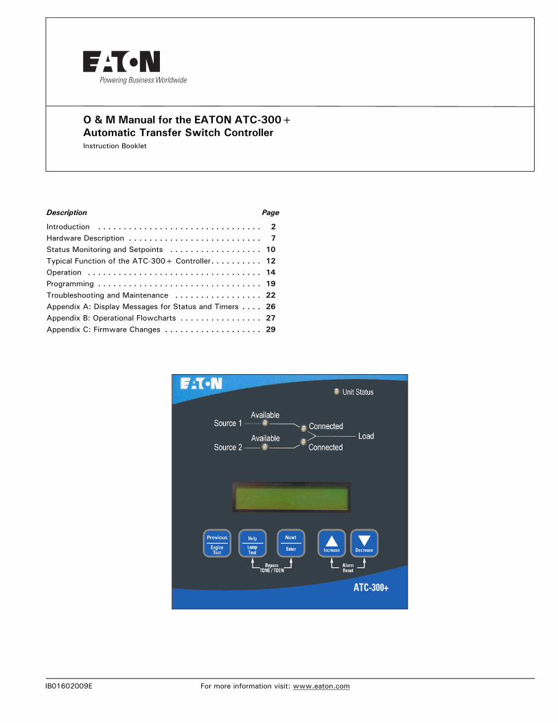
1 Unit Status
2 Source 1 Available
3 Source 1 Connected
4 Source 2 Available
5 Source 2 Connected
There are seven input functions accessible through the pushbut-tons:
1 Help/Lamp Test
2 Previous / Engine Test
3 Next/Enter
4 Increase
5 Decrease
6 Alarm Reset
7 Bypass Time Delay (TDNE, TDEN)
Figure 1. The ATC-300+ Controller Front Panel.
2.2.1 The Output Function Components
The Display
A 2-line, 16-character alphanumeric LCD Display module is used to display all ATC-300+ Controller monitored parameters, set-points, and messages in easy to read formats. The display has a green high contrast background that allows clear visibility of any information displayed. The display is continuously lit for clear visibility under poorly lit or no light conditions.
Six different displays can be presented via the LCD Display:
• Status Display• Source 1 Display• Source 2 Display• Time/Date Display• History Display• Setpoints Display
As a default when there are no active commands or timers being displayed, the display shows information from the source that is connected to the load. This is referred to as the “Home” screen.
Line 1: Source 1 or 2 Metered VoltageLine 2: Date Time
Example: Source 1 480V1/20/06 3:35PM
See Section 3 for more detailed information.
IB01602009E For more information visit: www.eaton.com
Instruction BookletPage 8 Effective: April 2017 ATC-300+ Automatic
Transfer Switch Controller
The LEDs
Unit Status
The green Unit Status LED blinks at a rate of once per second while in the ATC-300 Controller is in the “Run” Mode. This indi-cates that the ATC-300+ has completed a self-diagnostic and system diagnostic cycle. The self-diagnostic cycle checks include the:
• Microprocessor operation and• Memory operation.
The system diagnostic cycle checks include the:
• Output relay operation;• Control input operation; and• Transfer switch operation.
The Unit Status LED blinks at an increased rate while the ATC-300+ Controller is in the “Program” Mode for setpoint program-ming.
Source 1 Available
The white Source 1 Available LED illuminates if the Source 1 power source meets the criteria to be considered “available”. That is, when it is within its undervoltage/overvoltage/underfre-quency/overfrequency/voltage unbalance/phase reversal (if appli-cable) setpoint ranges for the nominal voltage and frequency setting.
Source 1 Connected
The green Source 1 Connected LED illuminates when the Source 1 switching device and its associated position indicating auxiliary contact are closed.
Source 2 Available
The amber Source 2 Available LED illuminates if the Source 2 power source meets the criteria to be considered “available”. That is, when it is within its undervoltage/overvoltage/underfre-quency/overfrequency/voltage unbalance/phase reversal (if appli-cable) setpoint ranges for the nominal voltage and frequency setting.
Source 2 Connected
The red Source 2 Connected LED illuminates when the Source 2 switching device and its associated position indicating auxiliary contact are closed.
2.2.2 The Input Function Components
The Pushbuttons and Combinations
Help/Lamp Test PushbuttonThe Help/Lamp Test pushbutton serves two functions. If the Help/Lamp Test pushbutton is pressed when a message is pres-ent on the LCD Display, a detailed description of the message will appear. The detailed message description will scroll across the bottom of the display. The detailed description can be aborted by pressing Help/Lamp Test key a second time.
If the LCD Display is displaying the Home screen when the Help/Lamp Test key is pressed, all of the LED’s will momentarily illumi-nate, then the following information will scroll across the display:
• Serial number of the ATC-300+ Controller;• Hardware revision number (= parts list revision number);• Feature code – a decodable string listing all optional features
programmed in the ATC-300+ Controller; and• Firmware version.
Previous/Engine Test PushbuttonWhen scrolling is being used, by pressing the Previous/Engine Test pushbutton, the LCD display will go to the previous screens. This new feature allows the user not to have to scroll all the way through anymore if a screen is missed.The Engine Test pushbut-ton allows the user to test the Source 2 (generator) engine. The engine test function can be set with the ATC-300+ Controller to one of three setpoint modes to allow flexibility in how the test is run:
0 No Load Engine Test;
1 Load Engine Test; or
2 Disabled.
The factory default is set to 1- Engine Load Test.
The controller will ask for the password to start the test. The fac-tory set password is 0300. For complete information on the Engine Test function, see Section 5.7.
Next/Enter PushbuttonThe Step/Enter pushbutton allows the user to scroll through the information and setpoint displays. By pressing the Next/Enter pushbutton, the information on the LCD Display will advance through the voltage(s), frequency, and status condition of Source 1, then Source 2, then the time and date information, then the history information, then the setpoints. The information on the LCD Display advances one step through the displayed information cycle with each depression of the Next/Enter pushbutton.
Increase PushbuttonThe Increase pushbutton allows the user to increase the value of the setpoints. When ATC-300+ Controller is in the “Program” Mode (to change setpoint values), each time the Increase push-button is pressed, the value of the displayed item will increase by one.
Decrease PushbuttonThe Decrease pushbutton allows the user to decrease the value of the setpoints. When ATC-300+ Controller is in the “Program” Mode (to change setpoint values), each time the Decrease push-button is pressed, the value of the displayed item will decrease by one.
Alarm Reset Function (Increase + Decrease Pushbuttons)Pressing the Increase and Decrease pushbuttons simultaneously will reset the Alarm function. In addition, if both pushbuttons are pressed simultaneously while viewing any of the historical logged values in the program mode, the value of the current item dis-played resets to zero.
Bypass Time Delay Function (Next/Enter + Help/Lamp Test)Pressing the Step/Enter and Help/Lamp Test pushbuttons simulta-neously will bypass the TDNE or TDEN functions when they actively counting. The “Bypass TDNE/TDEN” function does not have a user accessible, programmable setpoint for enable or dis-able.
For more information visit: www.eaton.com IB01602009E
Instruction BookletEffective: April 2017 Page 9ATC-300+ Automatic
Transfer Switch Controller
2.3 Rear Access AreaThe rear access area of the ATC-300+ Controller is normally accessible from the rear of an open panel door (Figure 2).
Figure 2. ATC-300+ Controller (Rear View).
All wiring connections to the ATC-300+ Controller are made at the rear of the chassis.
Note: To allow for uniform identification, the frame of reference when dis-cussing the rear access area is with the panel door open and the User fac-ing the back of the ATC-300+ Controller. See Figure 4 also.
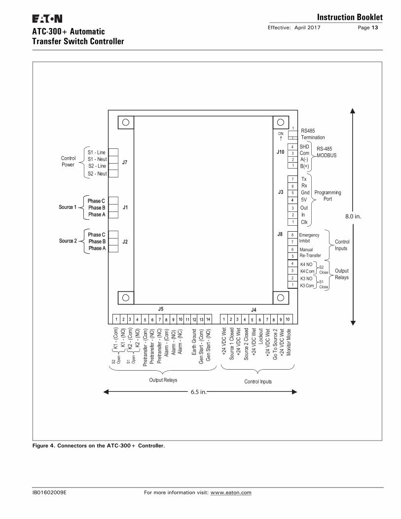
Located at the left rear of the chassis are connectors J1, J2, and J7. J1 and J2 provide for voltage monitoring of Source 1 and Source 2 respectively. J7 is provided for Sources 1 and Source 2 control power input. Located at the right rear of the chassis is the J3 programming port connector. The J4 and J5 connectors are located at the bottom of the controller. The J4 connector provides DC wetted connections for various control inputs. The J5 and J8 connectors provide dry relay contacts for primary con-trol outputs.
Applicable Testing UL Recognized ComponentMeets UL 1008Meets Intent of UL 991,Meets IEC 1000-4-2, 1000-4-3, 1000-4-4, 1000-4-5, 1000-4-6, 1000-4-11Meets CISPR 11, Class AComplies with FCC Part 15, Class A
Enclosure Compatibility NEMA 1, NEMA 3R, NEMA 4/4Xand NEMA 12UV Resistant ATC-300+ Faceplate
Input Control Contacts DC wetted (24 volts at 10 ma)
IB01602009E For more information visit: www.eaton.com
Instruction BookletPage 10 Effective: April 2017 ATC-300+ Automatic
Transfer Switch Controller
Section 3: Status Monitoring and Setpoints
3.1 Status DisplayThe Status Display provides messages regarding anything that is presently changing or happening to the ATS’s status, including source information, timer countdown, and failure reports. Refer to Appendix A for a complete list of Status Display messages.
Figure 3. The LCD Display.
3.1.1 Source 1 and Source 2 DisplaysThe Source 1 and Source 2 displays indicate the present status of the sources in terms of voltage and frequency. If the source is available, the condition display will be “SOURCE 1 GOOD” or “SOURCE 2 GOOD”. If it is unavailable, one of the following pos-sible conditions will be shown:
SOURCE 1 U-V SOURCE 2 U-V
The source voltage has dropped below the dropout setting and not risen above the pickup setting.
SOURCE 1 O-V SOURCE 2 O-V
The source voltage has risen above the dropout setting and not dropped below the pickup setting.
SOURCE 1 U-F SOURCE 2 U-F
The source frequency has dropped below the dropout setting and not risen above the pickup setting.
SOURCE 1 O-F SOURCE 2 O-F
The source frequency has risen above the dropout setting and not dropped below the pickup setting.
SOURCE 1 UNBAL SOURCE 2 UNBAL
The voltage unbalance has risen above the dropout setting and not dropped below the pickup setting.
S1 PHASE REVERSE S2 PHASE REVERSE
The phase sequence does not agree with the setpoint value, indi-cating that the phase sequence is reversed.
3.1.2 Time/Date DisplayThe Time/Date Display indicates real time in terms of hours, min-utes, and seconds; and month, day, and year. It also indicates individual time and date items for programming purposes. The day of the week can also be set with 1 = Sunday, 2 = Monday, etc. The time, date, and day of the week can be set in the Pro-gram Mode.
3.1.3 History DisplayThe History Display indicates historical and cumulative counter values as follows:
Engine Run Time
This counter will log the generator run time in hours. Time will start being logged at the time the GEN START contacts are closed, and it will stop as soon as they are opened. This counter will count up to 9999 hours and then turn over to 0000. It can be reset to zero in the Program Mode.
Source 1 Connected Time
This counter logs the time in hours that Source 1 has been con-nected to the load. Time will be logged while the SOURCE 1 CLOSED control input is in the “connected” state. This counter will count up to 9999 hours and then turn over to 0000. It can be reset to zero in the Program Mode.
Source 2 Connected Time
This counter logs the time in hours that Source 2 has been con-nected to the load. Time will be logged while the SOURCE 2 CLOSED control input is in the “connected” state. This counter will count up to 9999 hours and then turn over to 0000. It can be reset to zero in the Program Mode.
Source 1 Available Time
When Source 1 meets the voltage and frequency setpoint criteria, this counter logs the time in hours. This counter will count up to 9999 hours and then turn over to 0000. It can be reset to zero in the Program Mode.
Source 2 Available Time
When Source 2 meets the voltage and frequency setpoint criteria, this counter logs the time in hours. This counter will count up to 9999 hours and then turn over to 0000. It can be reset to zero in the Program Mode.
NOTICEALTHOUGH A WIDE VARIETY OF PARAMETERS AND SETPOINTS CAN BE DISPLAYED, THEY ARE NOT DISPLAYED IF THEY WERE NOT ORIGINALLY ORDERED AND PROGRAMMED.
NOTICEWHETHER VIEWING OR PROGRAMMING, THE DISPLAY RETURNS TO THE HOME SCREEN IF NO PUSHBUTTON ACTIVITY IS DETECTED FOR APPROXIMATELY 2.5 MINUTES.
LCD DISPLAY
For more information visit: www.eaton.com IB01602009E
Instruction BookletEffective: April 2017 Page 11ATC-300+ Automatic
Transfer Switch Controller
Load Energized Time
When either of the two sources is connected to the load and the connected source is available, this counter will start logging the time in hours. This counter will count up to 9999 hours and then turn over to 0000. It can be reset to zero in the Program Mode.
Total Number of Transfers
This counter logs the number of transfer cycles that occur. This counter will count up to 9999 cycles and then turn over to 0000. It can be reset to zero in the Program Mode.
Reason/Date/Time for the 16 Most Recent Transfers
The 16 most recent transfer events are stored in history and may be viewed at the LCD Display as follows:
• Use the Step/Enter pushbutton to step to the “TRANSFER HIS-TORY” message.
• Press the Increase pushbutton to display the most recent trans-fer event (T01) along with the type and cause of the event.
• Press the Decrease pushbutton to display the date and time of the event. Continually pressing the Decrease pushbutton will cycle the display between the event display and the date/time of event display.
• Press the Increase pushbutton to display the next most recent transfer event (T02).
• Pressing the Step/Enter pushbutton, while viewing any of the transfer history displays, will exit the Transfer History displays.
3.1.4 Setpoints DisplayThe Setpoints Display indicates presently programmed set-points. The setpoints can be altered with valid password entry. Refer to Section 6 for more details on setpoints.
3.1.5 Help DisplayThis display presents moving language messages, explanations, and prompts to assist the operator. When the Help/Lamp Test Pushbutton is pressed and released a second time during the scrolling of a message, the message is aborted.
IB01602009E For more information visit: www.eaton.com
Instruction BookletPage 12 Effective: April 2017 ATC-300+ Automatic
Transfer Switch Controller
Section 4: Typical Function of the ATC-300+ ControllerThe ATC-300+ Controller operates as follows and is shown in Figure 4:.
The input connections of the ATC-300+ controller are wetted and work on an opening or closure of an external contact. The output connections are dry contacts and function depending on input connections and / or source availability.
120 Vac, 60 Hz is required to power the ATC-300+ controller. Power is supplied to either pins 1 and 2 or 3 and 4 on the J-7 connector.
Source 1 (S1) sensing is supplied on the J-1 connector; Source 2 (S2) sensing is supplied on the J-2 connector.
K1 and K2 relays, located on pins 1 and 2 (K1) or pins 3 and 4 (K2) on the J-5 connector, along with the K3 and K4 relays, located on pins 1 and 2 (K3) and pins 3 and 4 (K4) on the J8 connector, are use to control device position. S1 and S2 inputs are located on pins 1 and 2 (S1) or pins 3 and 4 (S2) on the J-4 connector and are used to sense device position.
K1 and K3 close until the S1 input is satisfied but no longer than 6 seconds before the S1 device Alarm is triggered and the K1 and K3 relays are deenergized. The K2 and K4 relays function the same as the K1 relay in that they close until the S2 input is satisfied (closed) but no longer than 6 seconds before the S2 device Alarm is triggered and the K2 and K4 relays are deener-gized. Either input MUST be satisfied prior to resetting the Alarm. The S1 and S2 connected inputs are wetted inputs that require a contact closure in order to be satisfied.
The S1 device Alarm will occur if the switch is commanded to go from S1 to S2 and the S1 connected input is NOT removed within 6 seconds after the command to transfer. The S1 device Alarm will also occur if the switch is commanded to go from S2 to S1 and the S1 connected input is NOT connected within 6 seconds after the command to transfer from the neutral position. That is the K2 relay closes AFTER TDNE or after TD PRE-TRAN times out, if the S1 connected input is NOT opened within 6 sec-onds the K2 relay will open and an S1 device error message, “SOURCE 1 DEVICE”, will be displayed.
A typical transfer request will begin with an S1 outage (S1 becomes unavailable per the programmed setpoints), Engine Test, or Plant Exercise function. After TDES, if programmed, counts down, the Generator Start contact will close. For a Plant Exercise or Engine Test, the S2 available light MUST become available within 90 seconds or the generator start contacts will reopen. Once S2 meets the requirements to be considered avail-able, then TDNE, if programmed, will time down. The pretrans-fer relay will energize if S1 is available. TD PRE-TRAN will time down if programmed and if S1 is available (Engine Test or Plant Exercise). The K2 relay will energize. The S1 connected input MUST open within 6 seconds (see above). K2 will open IF TDN is programmed. TDN will then time down and K2 and K4 will energize until the S2 connected input is closed (this MUST hap-pen within 6 seconds of K2/K4 closure or the S2 device alarm will trigger and the K2 and K4 relays will deenergize). Once the S2 connected input is satisfied, K2 and K4 will open and the pre-transfer relay will de-energize.
When S1 returns and becomes available per the programmed set-points, TDEN, if programmed, will time out. The pretransfer relay will energize. TD PRE-TRAN, if programmed, will time out. K1 will energize for no longer than 6 seconds or until the S2 con-nected input is removed. If the 6 seconds times out, then an S2 device Alarm will trigger and K1 will open. Once the input is removed, then K1 will open if TDN is programmed. TDN will time down and K1 and K3 will reclose until the S1 input is satis-fied, but for no longer than 6 seconds. If the 6 seconds is reached, then an S1 device Alarm will be triggered and the K1 and K3 relays will open. If the S1 connected input is satisfied, then K1 will open, the pretransfer relay will de-enerigize, and TDEC will time down and open the engine start contact.
The Go To Source 2 input (normally closed, open to initiate) causes the Engine Start contacts to close. Once the S2 sensing satisfies the setpoints programmed, then a transfer is initiated. The transfer functions as described above. The controller will maintain the Engine Start contacts and the S2 connected as long as the Go To Source 2 input is maintained. Once it is removed, a retransfer to S1, if S1 is available per the setpoints, will occur and functions as described above. “Go To Source 2” is dis-played on the controller.
The Monitor Mode input (normally open, close to initiate) is uti-lized to put the controller in a “Monitor” only state. No other inputs will affect the operation of the controller when the Moni-tor Mode input is initiated. The controller will ONLY monitor the voltage and frequency of the S1 and S2 inputs. Changing of the setpoints of the controller MAY be accomplished while in Moni-tor Mode. All setpoints are accessible and all timers can be reset. “ATS Not In Automatic” is displayed on the controller.
The Lockout input (normally closed, open to initiate) is utilized to place the controller in a state where it will NOT supply any out-puts regardless the inputs. It is used to monitor the state of any fault indicating devices. If the fault device trips due to an over current or over load condition, then a contact opening will place the controller in the Lockout state. The Alarm contact will change state when the lockout signal is sensed. “Lockout” is displayed on the controller. The fault indicating device MUST be manually reset (Alarm Reset Buttons) before the controller can be reset or the Alarm will continue to indicate. This manual reset is the difference between monitor mode and lockout.
For more information visit: www.eaton.com IB01602009E
Instruction BookletEffective: April 2017 Page 13ATC-300+ Automatic
IB01602009E For more information visit: www.eaton.com
Instruction BookletPage 14 Effective: April 2017 ATC-300+ Automatic
Transfer Switch Controller
Section 5: Operation
5.1 GeneralThis section specifically describes the operation and functional use of the ATC-300+ Controller. The practical use of and opera-tion within each category will be discussed. In this section, it is assumed that prior sections of this manual were reviewed and that the operator has a basic understanding of the hardware.
5.2 Automatic ModeThe Automatic Mode of the ATC-300+ Controller provides for automatic transfer and re-transfer from Source to Source as dic-tated by the features supplied and their programmed setpoint val-ues. It provides a summary of the ATC-300+ Controller intelligence and supervisory circuits that constantly monitor the condition of both the Source 1 and Source 2 power sources, thus providing the required intelligence for transfer operations. These circuits, for example, automatically initiate an immediate transfer of power when the power fails or the voltage level drops below a preset value. Exactly what the ATC-300+ Controller will initiate in response to a given system condition depends upon the combi-nation of standard and selected optional features.
5.3 Monitor ModeMonitor Mode is a special operating mode in which the ATC-300+ Controller does not provide control for transfer operations. The ATC-300+ will, however, continuously monitor both Source 1 and Source 2 voltages and frequencies.
The ATC-300+ will be in Monitor Mode when the “Monitor Mode” control input is in the “Connected” state as described in Section 5.4. While in the Monitor Mode of operation, the ATC-300+ LCD Display will display “ATS NOT IN AUTOMATIC”.
5.4 Control InputsThe ATC-300+ has five individual input control signals. The inputs are DC24 volts wetted contacts with the unregulated DC supply and appropriate current limiting to provide a nominal cur-rent of 10 mA per channel.
5.4.1 Control Input DescriptionsThe Control Input “State” definitions are as follows.
Connected - When the input is shorted by an external contact or connection.
Unconnected - When the input is NOT shorted by an external contact or connection.
The Control Input operations are defined as follows.
Source 1 Closed
When this input is in the “Connected” state, it indicates to the ATC-300+ Controller that the Source 1 device is closed. When this input is in the “Unconnected” state, it indicates to the ATC-300+ that the Source 1 device is open. This input is typically wired to the Source 1 device auxiliary contact that is closed when the Source 1 device is closed. The “Source 1 Closed” input is always enabled.
Source 2 Closed
When this input is in the “Connected” state, it indicates to the ATC-300+ Controller that the Source 2 device is closed. When this input is in the “Unconnected” state, it indicates to the ATC-300+ that the Source 2 device is open. This input is typically wired to the Source 2 device auxiliary contact that is closed when the Source 2 device is closed. The Source 2 input is always enabled.
Lockout
When the “Lockout” input is in the “Unconnected” state, the ATC-300+ Controller will not permit an automatic transfer oper-ation. When the “Lockout” input is in the “Unconnected” state, the LCD Display will be active continuously. It will read “Lock-out” on Line 2 of the LCD Display screen immediately, regardless of any controller or switching device operation. When the “Lock-out” input is in the “Connected” state and the Alarm is manually reset (reset buttons on the front panel), the ATC-300+ will per-mit automatic transfer operation. This input is typically wired to the normally closed Source 1 and Source 2 device alarm contact that opens when one of the devices has tripped due to a fault current. The “Lockout” input is selectable as enabled or disabled via factory control only.
Go To Source 2
When the “Go to Source 2” input is in the “Connected” state, the ATC-300+ Controller is be in a normal, automatic operation mode. When the “Go To Source 2” input is in the “Uncon-nected” state, the ATC-300+ controller will initiate a generator start and then transfer to the Source 2 power source. The ATC-300+ will maintain the connection to Source 2 until the input changes to the “Connected” state, upon which it will initiate a re-transfer to the Source 1 power source. When the “Go To Source 2” input is in the “Unconnected” state (no jumper or contact), the LCD Display will be active continuously. Active time delays will be constantly displayed on Line 1, with real-time remaining countdown to zero status. It will constantly read “Go To Source 2” on Line 2 of the LCD Display. This operation is “failsafe”. The “Go To Source 2” input is always enabled. The “Go To Source 2” input does not have a user accessible programmable setpoint for enable or disable.
Monitor Mode
When the “Monitor Mode” input is in the “Unconnected” state, operation of the ATC-300+ Controller will not be effected. When the “Monitor Mode” input is in the “Connected” state, the ATC-300+ will monitor the Source 1 and Source 2 voltages and frequencies but will not provide any control capabilities. When the “Monitor Mode” input is in the “Connected” state, the ATC-300+ LCD Display will be active continuously and will constantly read “ATS” on Line 1 and “NOT IN AUTOMATIC” on Line 2 of the LCD Display. The “Monitor Mode” input is selectable as enabled or disabled via factory control. The “Monitor Mode” input does not have a user accessible programmable setpoint for enable or disable. This is NOT a “failsafe” operation.
Manual Re-TransferWith manual operation set, momentary closure on Pins 5 and 6 of Connector J8 allows ATC-300+ to proceed with a re-transfer operation at the operators discretion. Should a failure of the emergency source occur while waiting for the manual return, the re-transfer proceeds automatically.
For more information visit: www.eaton.com IB01602009E
Instruction BookletEffective: April 2017 Page 15ATC-300+ Automatic
Transfer Switch Controller
Emergency InhibitThis input is located on Pins 7 and 8 of Connector J8 and is enabled when the Emergency Inhibit optional feature (36) is enabled. The contact is closed for normal operation. Opening this contact will activate the Emergency Inhibit input.If the Emergency Inhibit contact is opened when the load is con-nected to the Normal Source, no action will be taken if the Nor-mal Source is available. If the Normal Source is not available, an immediate transfer to the neutral position will occur.If the Emergency Inhibit contact is opened when the load is con-nected to the Emergency Source, the ATC-300+ will transfer the load to the Normal Source if it is available. If the Normal Source is not available, an immediate transfer to the neutral position will occur.The Emergency Inhibit input is only active when either Source 1 or Source 2 is preferred. This input is not active when the Pre-ferred Source selection is set to None.The Emergency Inhibit input takes priority over the Go To Emer-gency input if both inputs are activated at the same time. In this case, the generator will start but a transfer to the Emergency Source will be inhibited until the Emergency Inhibit input is de-activated. A jumper must be included between Pins 7 and 8 of connector J8 when a two position contactor is being used. The Inhibit function transfers to the open position which is on a three position contactor.
5.5 Output RelaysThe primary control outputs of the ATC-300+ Controller are dry relay contacts. These relays are comprised of one latching “Form A” relay to provide the generator start contacts, and six conven-tional coil “Form C” relays (four of which implement only the Form A contact) necessary to complete the electrical control function. Since the outputs were tested per the UL 1008 Dielec-tric Test, the dielectric rating for each output is a minimum of 1500 Vac. The output relays are pulsed to eliminate error caused by software “races” between Lockout and Source 1 or Source 2 Closed inputs.
The latched coil relay is UL/CSA rated at 5 A, 1/6 HP, 250 Vac. The DC rating is 5 A, 30 Vdc, with a 150 W maximum load. The remaining conventional relays are UL/CSA rated at 10 A, 1/3 HP, 250 Vac. The DC rating is 10 A at 30 Vdc.
Note: The ATC-300+ Controller MUST BE properly grounded at J-5, Pin 12 for proper operation.
The Output Relay functions are divided into two categories:
• Customer Connections and• Transfer Operation Contacts.
5.5.1 Output Relay DescriptionsSpecifically the relay functions are as follows.
5.5.1.1 Customer Connections
THE ATC-300+ CONTROLLER MUST BE PROPERLY GROUNDED AT J-5, PIN 12 FOR PROPER OPERATION.
CAUTION
IB01602009E For more information visit: www.eaton.com
Instruction BookletPage 16 Effective: April 2017 ATC-300+ Automatic
For more information visit: www.eaton.com IB01602009E
Instruction BookletEffective: April 2017 Page 17ATC-300+ Automatic
Transfer Switch Controller
Generator Start Relay
This latching relay is the generator start relay for system configu-rations that employ a generator as the Source 2 power source. This relay provides a Form A contact of silver alloy with gold flashing for closure of the generator start circuit.
The Form A contact is implemented with the Common Pin (J-5, Pin 13) and the Normally Open Pin (J-5, Pin 14). The generator start relay contacts are rated for 5 A, 1/6 HP @ 250 Vac. The DC rating is 5 A @ 30 Vdc with a 150 W maximum load.
Alarm Relay
The alarm relay is de-energized to indicate an absence of an alarm state and energized to indicate the presence of an alarm condi-tion. Alarm conditions include the following.
1. Improper circuit breaker (or contactor) operation (breaker [or contactor] fails to open or close within six [6] seconds)
2. Motor operator failure (Breaker Type ATS only)
3. Lockout
4. Failsafe condition
5. Aborted engine test due to Source 2 unavailability
6. Aborted plant exerciser test due to Source 2 unavailability
7. Unsuccessful in-phase transition
The alarm relay will remain energized until “Alarm Reset” is pressed.
The full Form C contact of this relay may be wired to an alarm annunciator panel to indicate a problem with the ATS. The full Form C contact of this relay is implemented with the Common Pin (J-5, Pin 8), the Normally Closed Pin (J-5, Pin 10), and Normally Open Pin (J-5, Pin 9). The alarm relay contacts are rated for 10 A, 1-3 HP @ 250 Vac. The DC rating is 10A @ 30 Vdc.
Pre-transfer Relay
This Form C relay opens/closes on a timed basis (adjustable from 1 to 120 seconds) prior to the transfer operation between two available sources to allow the load to be de-energized prior to transfer in either direction. After TDNE/TDEN times out, this relay energizes and the Pre-transfer timer (TD PRE-TRAN) starts timing. After TD PRE-TRAN times out, the transfer proceeds. The pre-transfer relay de-energizes after the transfer is complete.
The full Form C contact of this relay is implemented with the Common Pin (J-5, Pin 5), the Normally Closed Pin (J-5, Pin 7), and the Normally Open Pin (J-5, Pin 6). The pre-transfer relay contacts are rated for 10 A, 1-3 HP @ 250 Vac. The DC rating is 10 A @ 30 Vdc.
5.5.1.2 Transfer Operations ConnectionsK1, K2, K3, and K4 are factory wired to operate the transfer switch. The relay contacts for each are rated for 10 A, 1/3 HP @ 250 Vac. The DC rating is 10 A @ 30 Vdc. K1 - K4 are Form C relays but only the Form A contacts are used to operate the transfer switch.
Note: The ATC-300+ Controller MUST BE properly grounded at J-5, Pin 12 for proper operation.
Output Relay K1
This Form A relay is used for control of the transfer switch to close Source 1in the transfer switch. The K1 relay momentarily energizes until the ATC-300+ senses that the Source 1 breaker/switch is closed, then K1 de-energizes. The K1 outputs are com-mon pin (J-5, pin 1) and Normally Open pin (J-5, pin 2).
Output Relay K2
This Form A relay is used for control of the transfer switch to close the Source 2 in the transfer switch. The K2 relay momen-tarily energizes until the ATC-300+ senses that the Source 2 breaker/switch is closed, then K2 de-energizes. The K2 outputs are common pin (J-5, pin 3) and Normally Open pin (J-5, pin 4).
Output Relay K3
This Form A output is used to close Source 1 of the switch. The K3 relay momentarily energizes until the ATC-300+ senses that the Source 1 is closed, then K3 de-energizes. The K3 outputs are common pin (J-8, pin 1) and Normally Open pin (J-8, pin 2).
Output Relay K4
This Form A output is used to close Source 2 of the switches. The K4 relay momentarily energizes until the ATC-300+ senses that the Source 2 is closed, then K4 de-energizes. The K4 out-puts are common pin (J-8, pin 3) and Normally Open pin (J-8, pin 4).
5.6 Operating Voltage and MeasurementsThe ATC-300+ Controller operates with control power from 65 to 145 Vac. The ATC-300+ operates on single and three phase systems with selectable frequency settings of 50 or 60 Hz depending on the system ordered.
The ATC-300+ can perform the time delay engine start function without control power. This is accomplished by the use of a supercap and a latching control relay. The supercap stays charged for up to two minutes to power the logic circuitry that provides the start pulse to the latching control relay. After power has been turned off for approximately two minutes, the Engine Start contact will be closed. The latching control relay, which controls the generator, only changes state when it receives start or stop pulses.
The ATC-300+ Controller operates directly from the line sensing inputs of the Source 1 and Source 2 power sources. The nominal operating system inputs are from 120 to 600 Vac. The standard system assumes that neutral is available and that the transfer mechanism can therefore be powered from an available 120 Vac source. If a neutral conductor is not available, a 120 Vac supply is created by an external transformer.
All voltage monitoring and measurements are true RMS measure-ments. J5-12 must be grounded to the frame for the controller to function correctly.
IB01602009E For more information visit: www.eaton.com
Instruction BookletPage 18 Effective: April 2017 ATC-300+ Automatic
Transfer Switch Controller
5.7 Engine TestThe Engine Test is intended to permit the periodic performance of tests of the system. The exact test conditions are determined by the programmed setpoints. The operator-selected parameters include setting the engine run time and the Test Mode. Refer to Table 2 for test programming details.
There are three test modes:
0 No Load Engine Test;
1 Load Engine Test; or
2 Disabled.
The factory default is set to 0 - No Load Engine Test
Note: If the Source 2 power source is not programmed as a generator, this function will be inactive.
IF THE ATS IS UNABLE TO PROCESS A ENGINE TEST REQUEST DUE TO THE ATS STATUS, THE REQUEST IS IGNORED.
When the Engine Test pushbutton is pressed, the following mes-sage will appear on the LCD Display:
Line 1: Password 0 3 0 0 defaultLine 2: Use Inc/Dec & Step
After entering the 4-digit password and pressing the Step/Enter pushbutton, the ATC-300+ will display the Time Delay on Engine Starting (TDES) timer countdown. Once the TDES countdown reaches zero, the ATC-300+ Controller will initiate an engine start. The engine run duration will be per the Engine Run Test Time setpoint.
If the (0) No Load Engine Test Mode has been selected, the trans-fer from Source 1 to Source 2 will not occur. If the (1) Load Engine Test Mode has been selected, the transfer from Source 1 to Source 2 will occur after the generator output has reached the specified setpoints. If the (2) Disabled Mode has been selected, or if the “Number of Generators” setpoint is pro-grammed to zero, the Engine Test will not occur.
All enabled and programmed time delays will be performed per the setpoints during an engine test. The time delays will appear on the LCD Display with “countdown to zero” when active. Depending on the setpoints and the optional features selected with the ATC-300+ Controller, these can include:
• TDES;• Time Delay Normal to Emergency (TDNE);• Time Delay Emergency to Normal (TDEN);• Time Delay for Engine Cooldown (TDEC);• Time Delay Neutral (TDN); and• Pre-transfer Delay Signal (TD PRE-TRAN).
All operations are “Failsafe”, that is they prevent disconnection from the only available power source and also force a transfer or re-transfer operation to the only available power source.
During an engine test, if the Engine Test pushbutton is pressed a second time before the Engine Test is complete and correct pass-word has been entered; the Engine Test will be terminated. An engine test may also be aborted in the following ways:
1. If the Emergency Source does not become available within 90 seconds of the ATC-300+ providing the engine start command;
2. If, during the TDNE countdown, the Emergency Source goes unavailable more than three times (Each time, TDNE will restart);
3. If the Emergency Source is powering the load and it goes unavailable for more than the TDEF setting; and
4. If the Normal source becomes unavailable.
When an engine test is aborted due to an unavailable source during TDNE countdown, the Alarm relay will energize, a “TEST ABORTED” message with appear on the display, and the event will be logged into the Transfer History as “Aborted Test”.
5.8 Plant Exerciser
THE PLANT EXERCISER FEATURE ALLOWS FOR AUTOMATIC PRO-GRAMMING OF THE DESIRED TEST CYCLE ON A DAILY, 7-DAY, 14-DAY, OR 28-DAY BASIS. IF THE ATS IS UNABLE TO PRO-CESS A PLANT EXERCISER REQUEST DUE TO THE ATS STATUS, THE REQUEST IS IGNORED.
The plant exerciser is a feature that provides an automatic test of the generator. The test can be run daily, every 7 days, every 14 days, or every 28 days with durations equal to the programmed engine test time. Two optional modes of plant exercising are available:
• No Load Exercise; and• Load Exercising with “Failsafe”.
The ATC-300+ Controller allows the user to program the exact day, hour, and minute that the Plant Exercise will occur. This allows for the Plant Exercise to take place at the most opportune time for the specific facility.
The hour and minute that the Plant Exerciser is performed are pro-grammed with the “PE HOUR” and “PE MINUTE” setpoints where “PE HOUR” is in military time (1:00 PM = 13:00) and the “PE MINUTE” can be set from 0 to 59. The test day is programmed with the “PE DAY” setpoint. The ATC-300+ Controller com-pares the “PE DAY” setpoint with the “WEEKDAY” setting, which is set along with the time and date. If a 7-day plant exercise is programmed, the selections are from “1 SUN” through “7 SAT”.
If a 14-day plant exercise is programmed, the “PE DAY” setpoint can be set from “1 SUN” to “14 SAT” where “1 SUN” is the first Sunday of the 14-day period and “14 SAT” is the second Satur-day of the 14-day period.
If a 28-day plant exercise is programmed, the “PE DAY” setpoint can be set from “1 SUN” to “28 SAT” where “1 SUN” is the first Sunday of the 28-day period and “28 SAT” is the fourth Saturday of the 28-day period.
If desired, the Plant Exerciser can be disabled by choosing “OFF” for the “Plant Exer-“ setpoint.
NOTICE
NOTICE
For more information visit: www.eaton.com IB01602009E
Instruction BookletEffective: April 2017 Page 19ATC-300+ Automatic
Transfer Switch Controller
Plant Exercising in the Load Exercising Mode is “Failsafe”. If the generator fails during testing for any reason, the ATC-300+ will signal the transfer switch to return to the Source 1 power source. The ATC-300+ will display “FAILSAFE” until a pushbutton is pressed.
5.9 In-phase Transition (Optional Feature 32F)The In-phase transition feature permits a transfer or re-transfer only between 2 available sources that have a minimal phase angle difference (synchronized). The In-phase transition feature includes user-adjustable permissible frequency difference setpoint (0.0 - 3.0 Hz) and a programmable Sync timer. The Sync times will count down and be displayed while waiting for the two sources to synchronize.
In-phase transition is an open transition with both sources in-phase. An anticipatory scheme is used for controlling the circuit breakers. The advance angle is calculated based on the fre-quency difference between the two sources and also the response time of the breaker. This results in the optimum recon-nect angle of 0 degrees for all of the frequency difference values.
Both sources must be available and the frequency difference must be less than the in-phase transition frequency difference setpoint (0.0 to 3.0 Hz). When these conditions are met, the ATC-300+ Controller will monitor the phase difference between the two sources. The synchronization timer will count down and be displayed as “SYNC TIME” while waiting for synchronization to be detected. When the phase difference is within the advance angle window, the “transfer” command is given. This is an open transition but both sources will be in-phase when the transfer occurs.
In the event source 1 and source 2 fail to synchronize within a specified amount of time, due to excessive phase angle differ-ence or frequency difference, then the transfer will take place under delayed transition. Alarm relay will energize and failure will be logged into the transfer history as either “Sync Fail – Freq” or “Sync Fail – Phase” depending on whether the frequency differ-ence or the phase difference was excessive.
5.10 Program ModeThe ATC-300+ Controller is fully programmable from the device’s faceplate once the Password has been correctly entered. Any operator associated with programming the ATC-300+ Con-troller will quickly discover that ATC-300+ programming is just a matter of simple, repetitive steps. However, because of the importance placed on this function and its critical relationship to the proper functioning of the system, Section 6 of this manual is dedicated to the Program Mode. Refer to that section and Table 2 for details.
Section 6: Programming
6.1 Introduction
ALTHOUGH ALL ATC-300 CONTROLLER PROGRAMMABLE FEA-TURES ARE ADDRESSED IN THIS SECTION, ONLY THOSE ORDERED BY THE CUSTOMER AND INITIALLY PROGRAMMED AT THE FAC-TORY WILL APPEAR IN THE DISPLAY FOR PROGRAMMING CHANGES IN THE FIELD.
The ATC-300 Controller is fully programmable from the device’s faceplate or remotely through the communications port. Users can reprogram setpoints as well as other parameters. The time, date, and setpoints can only be changed while the device is in the Program Mode.
Program Mode is achieved by entering a valid password when prompted by the Setpoints screens. The Unit Status LED will blink at a faster rate when viewing the setpoints while in Program Mode.
WHILE IN THE PROGRAM MODE, THE ATC-300+ CONTROLLER IS NEVER OFF-LINE AND CONTINUES TO FUNCTION IN ACCORDANCE WITH PREVIOUSLY PROGRAMMED SETPOINTS.
6.2 PasswordTo enter the Program Mode, the ATC-300+ Controller requires a password to prevent unauthorized persons from modifying set-point values.
There are five screens related to the password, which is a four-digit number from 0000 to 9999.
1. VIEW YESSETPOINTS?
Use the Increase or Decrease pushbuttons to select Yes, then use the Step/Enter pushbutton to enter the selection and move to the next screen
2. CHANGE YESSETPOINTS?
Use the Increase or Decrease pushbuttons to select Yes or No, then use the Step/Enter pushbutton to enter the selection and move to the next screen. If No is selected, the user will be able to review the setpoints but not make any changes. If Yes is selected, the Password screen will appear. 0300 is the default password.
3. PASSWORD 0300(Use Inc/Dec)
Use the Increase or Decrease keys to scroll to the desired value (0 - 9) for the first digit, then use the Step/Enter key to enter the value and move to the next digit. Repeat for remaining three dig-its. After all four numerals of the password are entered, press the Step/Enter pushbutton to enter the password and proceed to the next screen. If an invalid password is entered, the LCD Dis-play shall read “Invalid Password” and the user must press the Step/Enter pushbutton to initiate another password entry sequence.
Note: The factory default password is “0300”. If the password is forgot-ten, contact the factory for the backdoor password.
There is a new feature that the user can set the SWITCH TYPE (Device) by simply changing the setpoint. The feature types are the:
• Breaker• 3 position contactor• 2 position contactor• 3K contactor• MG
This allows the ATC-300 controller to be completely program-mable by the end user with all options available. It cannot be read/changed by MODBUS.
NOTICE
NOTICE
IB01602009E For more information visit: www.eaton.com
Instruction BookletPage 20 Effective: April 2017 ATC-300+ Automatic
Transfer Switch Controller
4. CHANGE YESPASSWORD?
Use the Increase or Decrease pushbuttons to select Yes or No, then use the Step/Enter pushbutton to enter the selection and move to the next screen. If No is selected, the first Setpoint screen will appear. If Yes is selected, the following screen will appear.
5. NEW PASSWORD 0000(Use Inc/Dec)
Use the Increase or Decrease pushbuttons to scroll to the desired value (0 - 9) for the first digit of the new password, then use the Step/Enter pushbutton to enter the value and move to the next digit. Repeat for remaining three digits.
The user then steps through the setpoint screens and can change the setpoint values. During this time, the Unit Status LED will blink at a faster rate. At the end of the setpoint screens, the user will be prompted to save the setpoints.
6.3 Display Only ModeIn the Display Only Mode, the ATC-300+ Controller allows the user to view all setpoints and their programmed values. Each press of the Next/Enter pushbutton will advance the program to the next setpoint. Setpoint values CANNOT be changed while in the Display Only Mode.
6.4 Change Setpoints ModeIn the Change Setpoints Mode, the user can step through the Set-point screens and change the Setpoint values using the Increase and Decrease pushbuttons. During this time, the Unit Status LED will blink at a faster rate to indicate Program Mode. At the end of the setpoint screens, the LCD Display will read Save Setpoints? Either the Increase or Decrease pushbutton may be used to select either Yes or No”. The Next/Enter pushbutton is then pressed to enter the selection. If Yes is selected at the Save Setpoints? Screen, the ATC-300+ shall save the Setpoint settings and the LCD Display shall read Programming Setpoints to confirm entry. If “No” is selected, then all Setpoints will remain unchanged.
6.5 Programmable Features and Setpoints
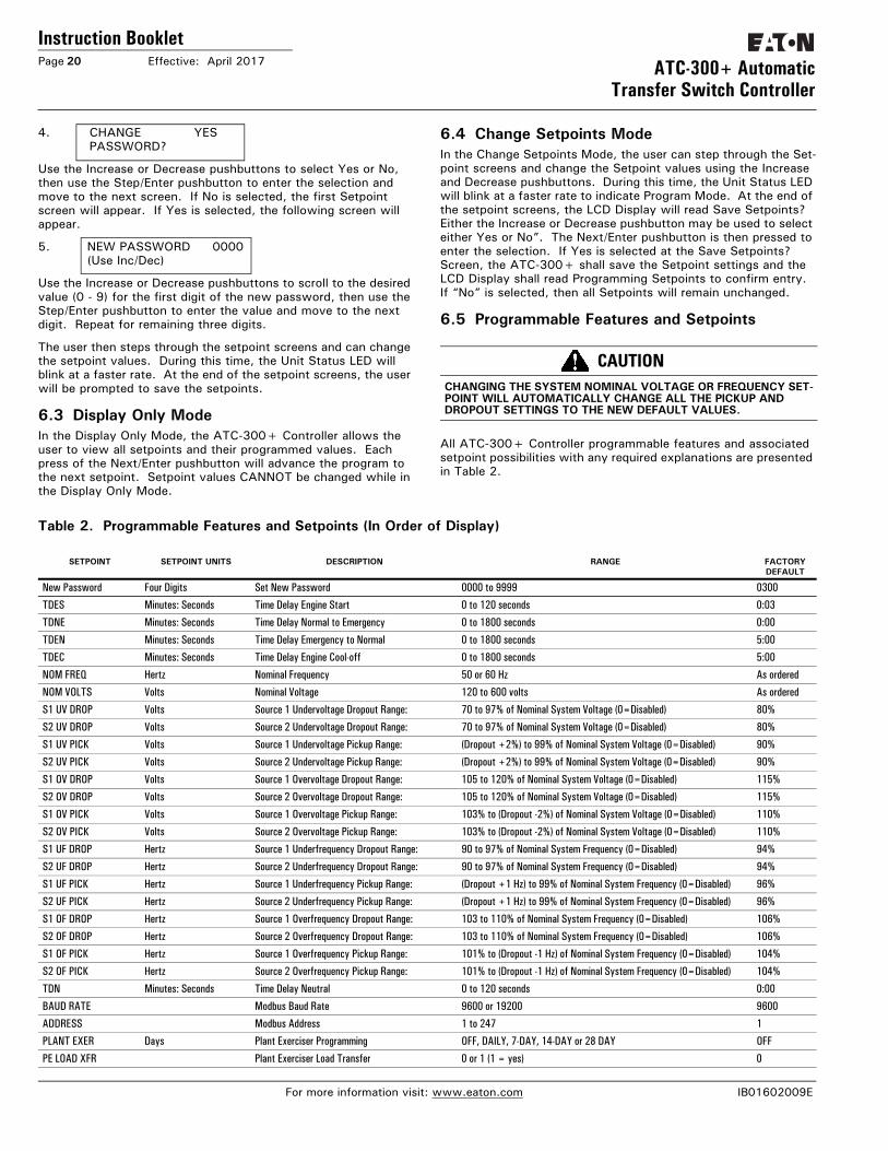
All ATC-300+ Controller programmable features and associated setpoint possibilities with any required explanations are presented in Table 2.
Table 2. Programmable Features and Setpoints (In Order of Display)
CAUTIONCHANGING THE SYSTEM NOMINAL VOLTAGE OR FREQUENCY SET-POINT WILL AUTOMATICALLY CHANGE ALL THE PICKUP AND DROPOUT SETTINGS TO THE NEW DEFAULT VALUES.
SETPOINT SETPOINT UNITS DESCRIPTION RANGE FACTORY DEFAULT
New Password Four Digits Set New Password 0000 to 9999 0300
TDES Minutes: Seconds Time Delay Engine Start 0 to 120 seconds 0:03
TDNE Minutes: Seconds Time Delay Normal to Emergency 0 to 1800 seconds 0:00
TDEN Minutes: Seconds Time Delay Emergency to Normal 0 to 1800 seconds 5:00
TDEC Minutes: Seconds Time Delay Engine Cool-off 0 to 1800 seconds 5:00
NOM FREQ Hertz Nominal Frequency 50 or 60 Hz As ordered
NOM VOLTS Volts Nominal Voltage 120 to 600 volts As ordered
S1 UV DROP Volts Source 1 Undervoltage Dropout Range: 70 to 97% of Nominal System Voltage (0=Disabled) 80%
S2 UV DROP Volts Source 2 Undervoltage Dropout Range: 70 to 97% of Nominal System Voltage (0=Disabled) 80%
S1 UV PICK Volts Source 1 Undervoltage Pickup Range: (Dropout +2%) to 99% of Nominal System Voltage (0=Disabled) 90%
S2 UV PICK Volts Source 2 Undervoltage Pickup Range: (Dropout +2%) to 99% of Nominal System Voltage (0=Disabled) 90%
S1 OV DROP Volts Source 1 Overvoltage Dropout Range: 105 to 120% of Nominal System Voltage (0=Disabled) 115%
S2 OV DROP Volts Source 2 Overvoltage Dropout Range: 105 to 120% of Nominal System Voltage (0=Disabled) 115%
S1 OV PICK Volts Source 1 Overvoltage Pickup Range: 103% to (Dropout -2%) of Nominal System Voltage (0=Disabled) 110%
S2 OV PICK Volts Source 2 Overvoltage Pickup Range: 103% to (Dropout -2%) of Nominal System Voltage (0=Disabled) 110%
S1 UF DROP Hertz Source 1 Underfrequency Dropout Range: 90 to 97% of Nominal System Frequency (0=Disabled) 94%
S2 UF DROP Hertz Source 2 Underfrequency Dropout Range: 90 to 97% of Nominal System Frequency (0=Disabled) 94%
S1 UF PICK Hertz Source 1 Underfrequency Pickup Range: (Dropout +1 Hz) to 99% of Nominal System Frequency (0=Disabled) 96%
S2 UF PICK Hertz Source 2 Underfrequency Pickup Range: (Dropout +1 Hz) to 99% of Nominal System Frequency (0=Disabled) 96%
S1 OF DROP Hertz Source 1 Overfrequency Dropout Range: 103 to 110% of Nominal System Frequency (0=Disabled) 106%
S2 OF DROP Hertz Source 2 Overfrequency Dropout Range: 103 to 110% of Nominal System Frequency (0=Disabled) 106%
S1 OF PICK Hertz Source 1 Overfrequency Pickup Range: 101% to (Dropout -1 Hz) of Nominal System Frequency (0=Disabled) 104%
S2 OF PICK Hertz Source 2 Overfrequency Pickup Range: 101% to (Dropout -1 Hz) of Nominal System Frequency (0=Disabled) 104%
TDN Minutes: Seconds Time Delay Neutral 0 to 120 seconds 0:00
BAUD RATE Modbus Baud Rate 9600 or 19200 9600
ADDRESS Modbus Address 1 to 247 1
PLANT EXER Days Plant Exerciser Programming OFF, DAILY, 7-DAY, 14-DAY or 28 DAY OFF
PE LOAD XFR Plant Exerciser Load Transfer 0 or 1 (1 = yes) 0
For more information visit: www.eaton.com IB01602009E
Instruction BookletEffective: April 2017 Page 21ATC-300+ Automatic
Transfer Switch Controller
Table 2 Programmable Features and Setpoints (Cont.)See tables in the appendix for Voltage and Frequency Pickup and Dropout settings.
SETPOINT SETPOINT UNITS DESCRIPTION RANGE FACTORY DEFAULT
PE DAY Days Plant Exerciser Day of the Week 1 SUN, 2 MON, 3 TUE, 4 WED, 5 THU, 6 FRI or 7 SAT
PE HOUR Hours Plant Exerciser Hour 0 to 23 0
PE MINUTE Minutes Plant Exerciser Minute 0 to 59 0
TEST MODE Test Mode 0, 1 or 2 (0 = No Load Engine Test, 1 = Load Engine Test, 2 = Disabled)
1
TER Hours: Minutes Engine run test time 0 min to 600 min 0:30
SWITCH TYPE Device types Breaker-3 position contactor-2 position contactor-3K-MG 2 position contactor
PHASES Three phase or single phase 1 or 3 AS ORDERED
VOLT UNBAL Volts Voltage Unbalanced 0 or 1 (1 = Enabled) 1
UNBAL DROP % Percent Percent for Unbalanced Voltage Dropout 5 to 20% of Phase to Phase Voltage Unbalance 12%
UNBAL PICK % Percent Percent for Unbalanced Voltage Pickup Dropout minus (UNBAL DROP % -2) to 3% 10%
UNBAL DELAY Seconds Unbalanced Delay Timer 10 to 30 0:20
TDEF Seconds Time Delay Emergency Fail Timer 0 sec to 6 sec 6
IN-PHASE Hertz In-Phase Transition 0 or 1 (1=Enabled) 1
IP FREQ DIFF Hertz In-phase Transition FrequencyDifference 0.0 Hz to 3.0 Hz 1.0
SYNC TIME Minutes In-phase Transition Synchronization Timer 1 min to 60 min 5
PHASE REV Phase Reversal OFF, ABC, or CBA OFF
DST ADJUST Day Light Savings 0 or 1 (1=Enabled) 1
MAN RETRAN Manual Retransfer 0 or 1 (1=Enabled) 0
LANGUAGE Selected Language English, French, or Spanish English
CHANGE TIME/DATE? Set Time and Date
Hours Set Hour 0 to 23 Eastern Standard Time
MINUTES Set Minute 0 to 59 Eastern Standard Time
WEEKDAY Set Weekday SUN, MON, TUE, WED, THU, FRI or SAT Eastern Standard Time
MONTH Set Month JAN or 01 Eastern Standard Time
DAY Set Day 1 to 31 Eastern Standard Time
YEAR Set Year Current Year Eastern Standard Time
RESET SYSTEM COUNTERS?
Yes or No No
RESET ALL? Resets all System Counters Yes or No No
RESET ENGINE RUN?
Hours Resets ENGINE RUN Counter 0 to 9999 XXXX
RESETS1 CONN
Hours Resets S1 CONN Counter 0 to 9999 XXXX
RESETS2 CONN
Hours Resets S2 CONN Counter 0 to 9999 XXXX
RESETS1 AVAIL
Hours Resets S1 AVAIL Counter 0 to 9999 XXXX
RESET S2 AVAIL
Hours Resets S2 AVAIL Counter 0 to 9999 XXXX
RESETLOAD ENERG
Hours Resets LOAD ENERG Counter 0 to 9999 XXXX
RESETTRANSFERS
Cycles (Counts) Resets TRANSFERS Counter 0 to 9999 XXXX
SAVE SETPOINTS?
Save Changed Setpoints Yes or No Yes
IB01602009E For more information visit: www.eaton.com
Instruction BookletPage 22 Effective: April 2017 ATC-300+ Automatic
Transfer Switch Controller
Section 7: Troubleshooting and Maintenance7.1 Level of RepairThis manual is written with the assumption that only transfer switch system troubleshooting will be performed. If the cause of malfunction is traced to an ATC-300, the malfunctioning unit should be returned to Eaton for a replacement.
7.2 ATC-300 Device TroubleshootingThe Troubleshooting Guide (Table 3) is intended for service per-sonnel to identify whether a problem being observed is external or internal to the unit. For assistance with this determination, con-tact Eaton. If a problem is identified to be external to ATC-300, proceed to Section 7.3 and continue troubleshooting.
If a message is flashing on top of the display and the cause of the fault is resolved, simply press increase-decrease buttons and the message will be removed.
Table 3. Troubleshooting Guide.
For ATS assistance, call Eaton Care at:877-386-2273 option 2, option 4, and then option 3
NOTICEDURING CONVERSATIONS WITH EATON CONCERNING TROUBLE-SHOOTING OR PRODUCT RETURN, THE CUSTOMER MAY BE ASKED FOR INFORMATION PERTAINING TO THE SOFTWARE VERSION AND OPTIONS INCLUDED IN THE SPECIFIC UNIT. THE SYSTEM INFO SCREEN HAS THE DATA REQUIRED FOR THE CONTROLLER. IF THE CONTROLLER IS NOT FUNCTIONAL USE THE LABEL ON THE BACK OF THE UNIT.
SYMPTOM PROBABLE CAUSE POSSIBLE SOLUTION(S)
All front panel indicator LED’s are off. Control power is deficient or absent.ATC-300 is malfunctioning.
Verify that control power is connected at J7 and that it is within specifications.Replace the unit.
Automatic LED is not blinking. Control power is deficient or absent.Stuck waiting for Neutral positionATC-300 is malfunctioning
Verify that control power is connected at J7 and that it is within specifications.Mechanical problem; No inputfrom limit switch.Replace the unit.
One or more voltage phases read incorrectly. Incorrect wiring.ATC-300 is malfunctioning.
Verify voltage with multimeter. Check wiring.Replace the unit.
Front panel pushbuttons do not work. Bad connection inside ATC-300. Replace the unit.
Unit did not accept new setpoints via front panel. Operator error. Make sure "Enter" is pressed when com-pleted.No pushbuttons pressed for 2.5 minutes.
See Section 5 for rules on programming setpoints.Avoid intervals of 2.5 minutes of inactivity with pushbuttons when changing set-points.
Voltage dropout and pickup setpoints are different than what was programmed.
Adjusted nominal voltage setpoint. Re-adjust all dropout and pickup setpoints to default values.
Frequency dropout and pickup setpoints are differ-ent than what was programmed.
Adjusted nominal frequency setpoints. Re-adjust all dropout and pickup setpoints to default values.
Changed undervoltage, overvoltage, underfre-quency, or overfrequency dropout setpoint and the pickup setpoint changed also.
Pickup upper or lower limit ranges are dependent upon dropout setpoints. To prevent misapplication, they are automatically adjusted when overlapping occurs.
Source 1 or Source 2 is not available when it should be.
Voltage and/or frequency is not within setpoint values. Verify voltage and/or frequency with multi-meter. Check programmed setpoint values.
Source 1 or Source 2 is not shown connected when it should be.
No input from S1 or S2 aux contacts.ATC-300 is malfunctioning.
Verify contact closure at desired control input on J4.
Replace the unit.
Engine fails to start after TDES times out. S1 or S2 Generator start relay contacts not closed.Incorrect wiring at generator.
Replace the unit.Check engine wiring/maintenance.
Engine starts at 2 minutes with TDES set over 2 Minutes.
Any TDES value above two minutes, with no power on the controller, will start the generator (fail-safe) after two minutes.
Power Controller with UPS or 24VDC (using DCT).
Engine fails to turn off after TDEC times out. S1 or S2 Generator start relay contacts not open.Incorrect wiring at generator.Connected LED not lit for either source.
Replace the unit.Check engine wiring.Verify contact closure at desired control input on J4. Replace the unit.
Unit will not perform an Engine Test. Incorrect password after Test button was pushed Engine Test setpoint is set to Disabled.Number of Generators setpoint is set to 0.
Re-enter correct password. The factory password is 0300Re-program Engine Test setpoint.Re-program Number of Generators setpoint.
For more information visit: www.eaton.com IB01602009E
Instruction BookletEffective: April 2017 Page 23ATC-300+ Automatic
Transfer Switch Controller
7.3 General Switch Problem Solving
This section explains basic troubleshooting for Transfer Switches. The particular switch instruction booklet should be used to trou-bleshoot. A basic problem solving effort is the first step to take prior to calling for assistance. Frequently, the effort will success-fully address most problems encountered. The problem solving procedure is presented in the following sections as observed Problem Symptoms and one or more possible Solution Steps. All of the steps presented may not apply to all transfer switches, depending upon the logic. Remember, only qualified individuals familiar with the transfer switch equipment and the system in which it is applied should attempt these problem solving proce-dures.
If a problem persists after having completed the problem solving procedure, contact an Eaton representative for further assistance. When calling for assistance, the following is the minimum infor-mation required to properly address the need:Note: If a message is flashing on top of the display and the fault is removed, simply press "Help" and then "Enter" and the message will be removed.
1. General Order Number (GO#) of transfer switch, plus related Item Number;
2. Catalog Number of transfer switch;
3. Actual location of transfer switch (type of facility, address, etc.);
4. Style number of the controller;
5. Company, name and position of individual representing com-pany;
6. Basic description of situation as it exists; and
7. Any results of problem solving steps taken and/or readings taken from the events and summaries.
Table 3. Troubleshooting Guide (Cont.).
SYMPTOM PROBABLE CAUSE POSSIBLE SOLUTION(S)
Plant exerciser (PE) failed to exercise. Incorrect date or time setting. Incorrect setpoint programmed for PE day and/or time.Generator voltage and/or frequency did not become available within 30 seconds of engine starting.
Verify real time settings for Time/Date.Re-program PE day and/or time setpoint.Verify voltage and/or frequency with multi-meter. Check programmed setpoint val-ues. Check engine maintenance.
Unit displays “Lockout.” No contact closure at Lockout programmed input. Verify Lockout input circuit is closed.
Unit displays “INHIBIT” No contact closure at Emergency Inhibit programmed Input
Check Emergency Inhibit Wiring.
Unit displays an S1 open or close error Source 1 circuit did not open when it was commanded to open.Source 1 circuit did not close when it was commanded to close.S1 Aux Close contacts did not open when Source 1 opened.S1 Aux Close contacts did not close when Source 1 closed
Check Source 1 circuit trip wiring. Press "Help" then "Enter" push-buttons to clear message. Check Source 1 circuit wiring. Press "Help" then "Enter" push-buttons to clear mes-sage. Check S1 Aux Close control input wiring on on J6-1,2. Press "Help" then "Enter" push-buttons to clear message. Check S1 Aux Close control input wiring on on J6-3,4. Press "Help" then "Enter" push-buttons to clear message.
Unit displays an S2 open or close error Source 2 circuit did not open when it was commanded to open.Source 2 circuit did not close when it was commanded to close.S2 Aux Close contacts did not open when Source 2 opened.S2 Aux Close contacts did not close when Source 2 closed
Check Source 2 circuit trip wiring. Press "help" then "enter" push-buttons to clear message. Check Source 2 circuit wiring. Press "help" then "enter" push-buttons to clear mes-sage. Check S2 Aux Close control input wiring on J6-1,2. Press "help" then "enter" push-buttons to clear message. Check S2 Aux Close control input wiring on J6-3,4. Press "help" then "enter" push-buttons to clear message.
NOTICEWHILE PERFORMING TESTING, IF AN UNDESIRED OR UNDOCU-MENTED RESULT OCCURS, FIRST CONTACT THE LOCAL GENSET DEALER. IF THE RESULT IS NOT CORRECTED, CONTACT THE EATON ATS TECHNICAL SUPPORT AT 1-877-386-2273 OPTION 2, OPTION 4, OPTION 3.
DANGERHAZARDOUS VOLTAGES IN AND AROUND TRANSFER SWITCH EQUIPMENT DURING THE PROBLEM SOLVING PROCESS CAN CAUSE PERSONAL INJURY AND/OR DEATH. AVOID CONTACT WITH ANY VOLTAGE SOURCE WHILE PROBLEM SOLVING. USE LOCK-OUT TECHNIQUES TO ASSURE POWER IS REMOVED.
WARNINGONLY PROPERLY TRAINED PERSONNEL FAMILIAR WITH THE TRANSFER SWITCH EQUIPMENT AND ITS ASSOCIATED EQUIP-MENT SHOULD BE PERMITTED TO PERFORM THE PROBLEM SOLV-ING FUNCTION. SPECIFICALLY, ONLY PERSONS CLASSIFIED AS QUALIFIED UNDER FAILURE, TO UTILIZE QUALIFIED PERSONNEL (UNDER NFPA 70E) SHOULD WORK ON EQUIPMENT. IF NOT, IT COULD RESULT IN PERSONNEL INJURY AND/OR DEATH.
The transfer switch should be tested monthly to ensure a non-failure during an actual power outage. The switching mecha-nism is an electrochemical type device tied to a controller, relays, etc., and operating these will ensure good operation. Not only is the switch exercised but usually the ATS is tied to a gen-erator which can then also be exercised.
IB01602009E For more information visit: www.eaton.com
Instruction BookletPage 24 Effective: April 2017 ATC-300+ Automatic
Transfer Switch Controller
7.3.1 Transfer Switch Appears InoperativeStep 1: Verify that all plugs and sockets are properly intercon-
nected. Assure that the SWITCH TYPE ( Device) setpoint is programmed for the type of switch the controller is be used on (2 position contactor, 3 position contactor, breaker, 3K contactor, Magnum).
Step 2: If the source available LED is not on or the display shows the wrong voltage, make sure the controller setpoints match the system voltage. Verify that the correct system voltage is at the switch.
Step 3: Verify that the voltage selection plug on the transformer is in the proper position to match the system voltage.
Step 4: Look for any obviously burned components. Determine the cause and rectify, if possible. Replace defective components after the cause is determined.
Step 5: Is switch closed on source 1? Verify whether or not the system voltage now appears on the load terminals.
If YES: Proceed to check logic for problems in respective logic instruction book.
If NO: Check all power connections and the switching mechanism. What does the controller show for voltages on the main screen?
7.3.2 Transfer Switch Will Not Automatically Transfer to NormalStep 1: Is Option 29G installed? If so, there is a switch on the
door Labeled Auto Manual with either push buttons for S1 close, Trip, S2 Close or a three position switch with the same. The Auto Manual selector-switch must be in Auto for it to run with the controller.
Step 2: Is Option 9B installed? If so, there is a selector switch labeled “Maintenance”(or "Monitor Mode" for contactor-based switches.
If YES: Verify selector switch is in the “Operate” position.
If NO: Proceed to Step 3.
Step 3: Are the correct line voltage and frequency available at terminals N1, N2, and N3? Record the readings.
If YES: Proceed to Step 4.
If NO: Is the switch a source swap?.
Step 4: Is the transformer voltage selector plug in the correct position?
If YES: Proceed to Step 5.
If NO: Position plug correctly.
Step 5: Check the voltage on transformer NT1 by measuring voltage between voting relay KV-1 and GND. Is the volt-age measured 120 Vac (+/- 10 volts)? Record the read-ing.
If YES: Proceed to Step 6.
If NO: Check voltage transformer NT1.
Step 6: Is the power source available?
If YES:Proceed to Step 8.
If NO: Apply the correct system voltage to the Sourceconnections. or change the setpoints on the controller to match the system voltage
Step 7: Is the switch connected to the Source 2?
If YES:Proceed to Step 8.
If NO: Proceed to Step 9.
Step 8: If a problem persists, contact Eaton.
7.3.3 Transfer Switch Will Not Automatically Transfer To the Non-Preferred SourceStep 1: If the alternate source is a generator, is it running?
If YES: Proceed to Step 2.
If NO: Check the generator. Check the engine start contacts.
Step 2: Is the correct line voltage and frequency available at the Non-preferred source terminals? Record the readings.
If YES: Proceed to Step 3.
If NO: Verify that there is output voltage from the generator.
Step 3: Is the voltage selector plug in the correct position?
If YES: Proceed to Step 4.
If NO: Position plug correctly.
Step 4: Is the Preferred source available?
If YES: Proceed to Step 5.
If NO: Proceed to Step 6.
Step 5: Is a test Engine Test or Plant Exerciser being run, or is the "Go to Emergency" input energized?
If YES: Proceed to step 6.
If NO: STOP! The transfer switch should not transfer to source 2 if source 1 is available and connected.
For more information visit: www.eaton.com IB01602009E
Instruction BookletEffective: April 2017 Page 25ATC-300+ Automatic
Transfer Switch Controller
Step 6: Make sure that the setpoints are set according to the system voltage.
If YES: Proceed to Step 7.
If NO: .Adjust system voltage setpoints to match sys-tem voltage and phase.
Step 7: Is the Non-preferred switching device charged (3K con-tactor or Magnum)?
If YES: Proceed to Step 8.
If NO: Consult Magnum Breaker troubleshooting man-ual on how to charge the breaker before proceeding.
Step 8: Is the Preferred switching device OPEN?
If YES: Proceed to Step 10.
If NO: Proceed to Step 9.
Step 9: If this is a Magnum, measure the voltage between ter-minals B10 and B11 on the Preferred switching device (shunt trip). Is the voltage measured 120 Vac (+/- 10 volts)? Record the reading.
If YES: Refer to the Magnum Breaker maintenance manual IB#2C12060 and check the shunt tripPreferred switch.
If NO: Check the wiring to B10 and B11.
Step 10: If this is a Magnum measure the voltage between termi-nals B12 and B13 on the Non-preferred switching device (spring release coil). Is the voltage measured 120 Vac (+/- 10 volts)? Record the reading.
If YES: Refer to the Magnum Breaker maintenance manual IB#2C12060 and check the springrelease coil Non-preferred switching device.
If NO: Check the wiring to B12 and B13.
Step 11: If a problem persists, contact Eaton.
7.4 ReplacementFollow these steps to replace the ATC-300.Step 1: Turn off control power at the main disconnect or isola-
tion switch of the control power supply and lock it out to guard against other personnel accidentally turning it on. Follow all local safety requirements for transfer switches which includes appropriate PPE.
Step 2: Verify that all “foreign” power sources wired to the ATS Switch are de-energized. These may also be present on some of the terminal blocks.
Step 3: Before disconnecting any wires from the unit, make sure they are individually identified to ensure reconnection can be correctly performed. Taking a picture may help with re-connections.
Step 4: Disconnect all plugs and connectors going to the ATC-300.
Step 5: Remove the 4 mounting screws holding the unit against the door or panel. These are accessed from the rear of the unit.
Step 6: Set the screws aside for later use.
Step 7: Mount the replacement unit.
Step 8: Secure the ATC-300 to the panel with the 4 mounting screws.
Step 9: Re-connect all plugs and connectors to their proper socket on the ATC-300. Make certain that each plug is securely seated.
Step 10: Clear out all personnel, close all ATS panels, remove any lockouts, and restore control power. Ensure all set-points are correct.
7.5 Maintenance and CareThe ATC-300 is designed to be a self contained and maintenance free unit. The printed circuit boards are calibrated and confor-mally coated at the factory. They are to be serviced by factory trained personnel only. The front panel including the display can be cleaned lightly with a soap and water mixture.
For ATS assistance, call Eaton Care at:877-386-2273 option 2, option 4, and then option 3
CAUTIONSUPPORT THE ATC-300 FROM THE REAR SIDE WHEN THE SCREWS ARE LOOSENED OR REMOVED IN STEP 5. WITHOUT SUCH SUP-PORT, THE UNIT COULD FALL AND THE CONTROLLER COULD BE DAMAGED.
IB01602009E For more information visit: www.eaton.com
Instruction BookletPage 26 Effective: April 2017 ATC-300+ Automatic
Transfer Switch Controller
Appendix A: Display Messagefor Status and Timers
Display Message
TDEC Countdown cool-off timing before the generator contacts are opened.
TDES Countdown timing before the generator contacts are closed.
TDNE Countdown timing before Source 1 is disconnected before transferring to Source 2. Timing begins when Source 2 is available.
TDN Countdown timing with both sources disconnected from the load.
TDEN Countdown timing before Source 2 is disconnected before transferring to Source 1. Timing begins when Source 1 becomes available.
ATS NOT IN AUTOMATIC Control input for monitor mode is closed.
LOCK-OUT (Press Help) A trip condition has been detected by either breaker, and the system is locked-out from further transfers.
MAN RETRANSFER Waiting for an input signal to complete the manual re-transfer
EMERG INHIBIT Indicates that a transfer to the Emergency Source is inhibited because the Emergency inhibit input is acti-vated.
ENGINE RUN The engine run test timer is counting down before the test is completed. Pressing the Engine Test push-button will abort this timer and the test.
START TEST? To initiate an engine test sequence, press the Engine Test pushbutton again, or press Increase and Decrease pushbuttons simultaneously to clear.
WAIT FOR S2 Waiting for the Source 2 source voltage and frequency to become available.
TD PRE-TRAN Countdown timer before transfer begins. Timing begins after TDEN/TDNE expires or Manual Re-transfer input closes.
SYNC TIME Countdown timing in minutes while waiting for sources to synchronize during an in phase transition.
SOURCE 1 DEVICE Indicates that the Source 1 device (i.e. circuit breaker, contactor) failed to open or close
SOURCE 2 DEVICE Indicates that the Source 2 device (i.e. circuit breaker, contactor) failed to open or close.
TDEF Countdown timing before declaring Source 2 unavailable (accounts for momentary generator fluctuations).
TD UNBAL Countdown timer before declaring a source unavailable due to a voltage unbalance condition.
TEST ABORTED Indicates that an engine test or plant exercise was aborted after three unsuccessful attempts. Source 2 did not remain available while TDNE was timing.
GO TO SOURCE 2 Indicates that the load is transferring or connected to Source 2 because the Go To Source 2 control input is in the “unconnected” state.
FAILSAFE Indicates that the load was connected to Source 2 but Source 2 became unavailable so the load trans-ferred back to Source 1.
SETPOINTS ERROR Memory problem with the setpoints. Contact the factory.
OPTIONS ERROR Memory problem with the factory options. Contact the factory.
PROGRAMMING SETPOINTS Setpoints are being saved in memory.
WAITING FOR NEUTRAL Waiting for the neutral position to be reached by the switch.
WAITING FOR S1 TO CLOSE Waiting for the Source 1 device (i.e. circuit breaker, contactor) to close.
WAITING FOR S2 TO CLOSE Waiting for the Source 2 device (i.e. circuit breaker, contactor) to close.
For more information visit: www.eaton.com IB01602009E
Instruction BookletEffective: April 2017 Page 27ATC-300+ Automatic
Source 1 becomes unavailable (or Engine Test, Plant Exercise, Go To Emergency)
TDES timer times out
Send "Engine Start" signal(Energize Gen Start relay)
Is Source 2Available?
TDNE timer times out
Open Source 1(Energize K2)
Close Source 2(Energize K2)
Source 2 is powering the load
Is Source 1Available?
TDEN timer times out
Yes
No
No
Yes
Sends pretransfer signalTPRE timer times out
(If Source 1 is Available)
Open Source 2(Energize K1)
Close Source 1(Energize K1)
Source 1 is powering the load
TDEC timer times out
Remove "Engine Start" signal(De-energize Gen Start relay)
Sends pretransfer signalTPRE timer times out
IB01602009E For more information visit: www.eaton.com
Instruction BookletPage 28 Effective: April 2017 ATC-300+ Automatic
Transfer Switch Controller
In-Phase Transition Implementation
Source 1 is available
Close Source 1(Energize K1)
Source 1 is powering the load
Is Source 2Available?
TDNE timer times out
Open Source 1 and closeSource 2
(Energize K2)(Energize K4)
Source 2 is powering the load
Energize Alarm relay
Yes
No
No
Open Source 1 (Energized K2)
Receive request to transfer to Source 2(or Engine Test, Plant Exercise, Go To Emergency)
TDES timer times out
Send "Engine Start" signal(Energize Gen Start relay)
Sync timer times out
Sourcessynchronized
before Sync timertimes out
Yes
Sends pretransfer signalTPRE timer times out
(If Source 1 is available)
TDN timer times out if not programmed equal to zero
(For 2-position contactor ATS, TDN is not applicable & hence
recommended to program TDN=0)
Close Source 2 (out of Sync)(Momentarily energize K4)
Source 2 is powering the load
For more information visit: www.eaton.com IB01602009E
Instruction BookletEffective: April 2017 Page 29ATC-300+ Automatic
Transfer Switch Controller
Appendix C: Firmware Changes (Version 3.4 to current 4.2 April 2017).
1. Daylight Saving Time (when enabled) now follows the DST rules that went into effect in 2005.
2. Modbus communications now works with other devices on the same chain.
3. Individual, small groups, or all setpoints can now be written via Modbus function code 16. Previously all setpoints had to be written at one time.
4. Frequency averaging and tolerance of zero-crossing noise has been added to improve immunity to noise caused by non-lin-ear loads (VFDs).
5. Voltage averaging has been improved to eliminate the rela-tively slow ramp up/down when source voltage is applied/removed with a switch.
6. Under/Over Voltage/Frequency dropout/pickup setpoint limits have been simplified to one set for both breakers and contac-tors and now match the ATC-900.
7. Over voltage and under/over frequency can now be disabled by setting the dropout setpoint to zero via front panel or Modbus. Under voltage is always required as in the ATC-900.
8. Added 2-position contactor as a device option (switch type). When 2-position contactor is selected the TDN setpoint is not show on the front panel and TDN is forced to zero.
9. Device option/switch type (MCCB Breaker, 3 position contac-tor, 2 position contactor, 3K Contactor, Magnum) can now be set via Change Setpoints on the front panel. It cannot be read/changed via Modbus.
10. Front panel switch de-bouncing has been overhauled for bet-ter responsiveness and improved key repeat functionality when stepping though menus and changing setpoints.
11. The Engine Test key now provides a back-step function while navigating through menus.
12. Changing time/date and resetting system counters from the front panel no longer require password entry. There is a “Reset System Timers Yes/No”. If you say YES, it asks you if you want to “Reset all system timers yes/no”. If you say yes, it resets all of them. If you say no, it steps through each counter and asks you if you want to reset it or not.
13. Navigation through the setpoint menus has been updated to eliminate the momentary display of unused setpoints.
14. Added Emergency Inhibit handling for 2-position contactor like the ATC-900 (transfer to/stay on Source 1 even if it is not available).
15. Disabled in-phase (and skip the setpoint) when BRKR is selected from the front panel
IB01602009E For more information visit: www.eaton.com
Instruction BookletPage 30 Effective: April 2017 ATC-300+ Automatic
Transfer Switch Controller
This instruction booklet is published solely for information pur-poses and should not be considered all-inclusive. If further infor-mation is required, you should consult EATON.
Sale of product shown in this literature is subject to terms and conditions outlined in appropriate EATON selling policies or other contractual agreement between the parties. This literature is not intended to and does not enlarge or add to any such contract. The sole source governing the rights and remedies of any pur-chaser of this equipment is the contract between the purchaser and EATON.
NO WARRANTIES, EXPRESSED OR IMPLIED, INCLUDING WAR-RANTIES OF FITNESS FOR A PARTICULAR PURPOSE OR MER-CHANTABILITY, OR WARRANTIES ARISING FROM COURSE OF DEALING OR USAGE OF TRADE, ARE MADE REGARDING THE INFORMATION, RECOMMENDATIONS AND DESCRIPTIONS CONTAINED HEREIN. In no event will EATON be responsible to the purchaser or user in contract, in tort (including negligence), strict liability or otherwise for any special, indirect, incidental or consequential damage or loss whatsoever, including but not lim-ited to damage or loss of use of equipment, plant or power sys-tem, cost of capital, loss of power, additional expenses in the use of existing power facilities, or claims against the purchaser or user by its customers resulting from the use of the information, recommendations and description contained herein.
CSA is a registered trademark of the Canadian Standards Associ-ation. National Electrical Code and NEC are registered trademarks of the National Fire Protection Association, Quincy, Mass. NEMA is the registered trademark and service mark of the National Elec-trical Manufacturers Association. Uniform Building Code (UBC) is a trademark of the International Conference of Building Officials (ICBO). UL is a federally registered trademark of Underwriters Laboratories Inc.