[email protected]Identification of Individual Load Self-disconnection Following a Voltage Sag K. YAMASHITA*, H. KOBAYASHI, and Y. KITAUCHI Central Research Institute of Electric Power Industry Japan SUMMARY Voltage sag is one of the main causes of load self-disconnection, a large amount of which could adversely affect the short-term voltage stability and transient stability of power systems. In 1987, the Electric Technology Research Association (ETRA) set up a national technical committee in Japan to clarify the recent characteristics of voltage sag and load self-disconnection following a three-phase fault, and to identify countermeasures against voltage sag. Although the technical committee compiled an excellent report which is still widely referred to, the results are becoming obsolete. Due to the increasing percentage of inverter-based loads, there is much interest in the influence of voltage sag on the dynamic behavior of the rapid rise in post-fault load voltage for identifying technical issues concerning voltage phenomena. Therefore, in 2010 ETRA set up a national technical committee for reviewing past results. One important task of the committee was to update the load self- disconnection characteristics using modern loads. ETRA requested the Central Research Institute of Electric Power Industry (CRIEPI) to prepare for more than 40 kinds of load which are widely used in Japan with the aid of committee members in order to obtain load self-disconnection characteristics through field tests at the Akagi Testing Center of CRIEPI. A designated voltage dip (10% to 80%, in increments of 10%) and designated duration of voltage sag (2 ms to 500 ms) were applied to loads by a back-to-back (BTB) controller. Some of the loads started to be disconnected from the power system when the voltage sag exceeded 20% and no more loads could be disconnected when the voltage sag exceeded 70%. Overall, inverter-based air conditioners and refrigerators tended to be easily disconnected from the power system compared with non-inverter- based air conditioners and refrigerators. On the other hand, non-inverter-based lamps tended to be easily disconnected from the power system compared with inverter-based lamps. It is known that photovoltaic power generation systems (PV) are often disconnected from the power system due to the voltage sag caused by their own protection devices. As the use of PV spreads, this self-disconnection of PV could affect the transmission line system as well as distribution system. Because a voltage sag causes self-disconnection of both PV and load at the same instant, it is important to understand load self-disconnection characteristics more precisely for a dynamic security assessment assuming widespread use of PV in the power system. The results will therefore be useful for identifying technical issues concerning various phenomena in the power system in the future. KEYWORDS Load self-disconnection, voltage sag, inverter-based load, power system Oct.26-28, 2011, Thailand OP-08 CIGRE-AORC 2011 www.cigre-aorc.com
It is known that PV systems are often disconnected from the power system due to the voltage sag
caused by their own protection devices. As the use of PV spreads, this self-disconnection of PV could
6
affect the transmission line system as well as distribution system. Because a voltage sag causes self-
disconnection of both PV and load at the same instant, it is important to understand load self-
disconnection characteristics more precisely for a dynamic security assessment assuming widespread
use of PV.
Experiments at CRIEPI in 2010 clarified that some of the loads start to be disconnected from the
power system when the voltage sag exceeds 20% and that no more loads can be disconnected when
the voltage sag exceeds 70%. Overall, inverter-based air conditioners and refrigerators tend to be
easily disconnected from the power system compared with non-inverter-based air conditioners and
refrigerators. On the other hand, non-inverter-based lamps tend to be easily disconnected from the
power system compared with inverter-based lamps. It is concluded that if the usage of air-conditioners
increases, the amount of self-disconnected loads due to a severe voltage sag will increase.
Thus, Fig. 3 is useful for identifying technical issues concerning various power system phenomena in
power systems in the future, and will also contribute to the ongoing CIGRE WG C4.605 “Modelling
and aggregation of loads in flexible power networks.”
REFERENCES
[1] Electric Technology Research Association: “Countermeasure for voltage dips in power
systems,” Vol. 46, No. 3, 1990.
[2] Electric Technology Research Association: “Countermeasure technology for voltage dips in
power systems” Vol. 67, No. 2, 2011.
[3] K. Yamashita and O. Sakamoto: “A Study on Dynamic Behavior of Load Supply System
including Synchronous Generators with and without Load Drop,” Proceedings of IEEE 2010
PES General Meeting, 2010.
Short Biography of Main Author
Koji Yamashita received his B.S. and M.S. degrees from Waseda University, Tokyo,
Japan, in 1993 and 1995, respectively. Since 1995, he has been with the Department of
Power Systems at Central Research Institute of Electric Power Industry in Tokyo,
Japan. He is a regular member of CIGRE C4.605 WG.
1
Id tifi ti f I di id l L dId tifi ti f I di id l L dIdentification of Individual Load Identification of Individual Load SelfSelf disconnectiondisconnectionSelfSelf--disconnection disconnection
Following a Voltage SagFollowing a Voltage Sagg g gg g g
Koji Yamashita (CRIEPI)Koji Yamashita (CRIEPI)H Kobayashi (CRIEPI)Y Kitauchi (CRIEPI)
26th-27th of October 2011, Chiang Mai, Thailand
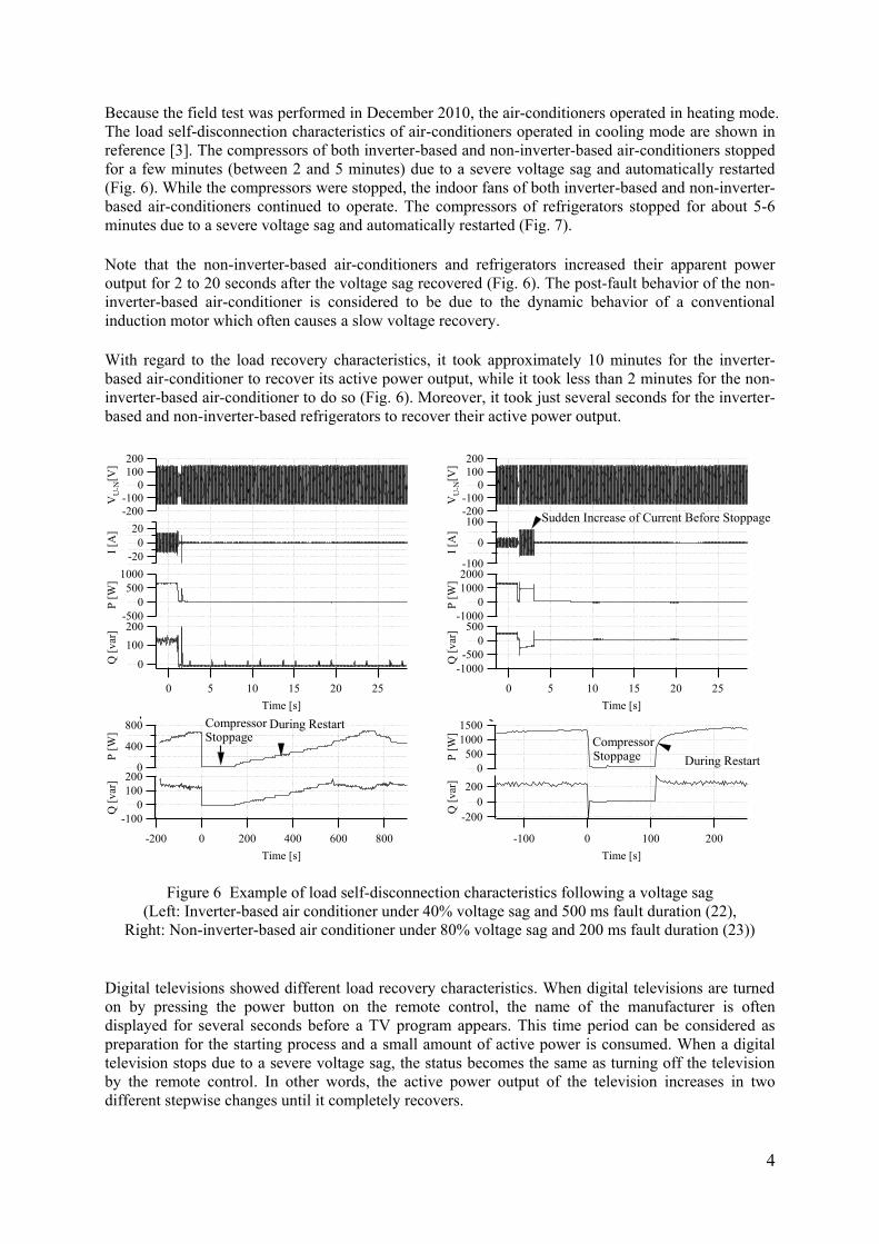
Introduction (Cont’d) Voltage sag is one of the main causes of load self-
disconnection, a large amount of which could adverselydisconnection, a large amount of which could adversely affect the short-term voltage stability and transient stability of power systems.of power systems.
In 1987, the Electric Technology Research Association (ETRA) set up a national technical committee in Japan to(ETRA) set up a national technical committee in Japan to clarify the recent characteristics of voltage sag and load self-disconnection following a three-phase fault and toself-disconnection following a three-phase fault, and to identify countermeasures against voltage sag.
Alth h th t h i l itt il d ll t Although the technical committee compiled an excellent report which is still widely referred to, the results are becoming obsoletebecoming obsolete.
Introduction Due to the increasing percentage of inverter-based loads,
there is much interest in the influence of voltage sag on thethere is much interest in the influence of voltage sag on the dynamic behavior of the rapid rise in post-fault load voltage for identifying technical issues concerning voltagevoltage for identifying technical issues concerning voltage phenomena.
In 2010 ETRA set up a national technical committee for In 2010 ETRA set up a national technical committee for reviewing past results and for updating the load self-disconnection characteristics using modern loadsdisconnection characteristics using modern loads.
Not only load self-disconnection characteristics but also th i h t i ti i ti t d th h ththeir recovery characteristics were investigated through the field tests
Classification of Loads Under Test (LUTs)4
Type ExampleInformation,Information,
communicationand electronics PC, Ethernet hub, DVD recorder, television
equipmentElectrically-powered
equipmentElectromagnetic switch, protective relay, signal
relay timerequipment relay, timer
Lamps Fluorescent lamp, light emitting diode (LED) lamp, discharge lampp, g p
The non-inverter-based loads that were selected in 1987 were firstly selected as the loads under test (LUTs). Inverter-based loads that did
not exist and were not used in 1987 were also selected as LUTs.
List of Loads Under Test (Con’d)5
Type of Loads Product and Description(1) Computer for personal use DELL: OPTIPLEX GX60 115/230 2/1A(2) C t f i d t i l HF W6500(2) Computer for industrial use : HF-W6500(3) Ethernet hub : LSW2-GT-16NSRR 100V 16.5W(4) Digital TV TOSHIBA: 37Z7000 100V 239W made in 2009(5) Digital TV SHARP: LC 20D30 100V 72W made in 2008(5) Digital TV SHARP: LC-20D30 100V 72W made in 2008 (6) DVD recorder SONY: RDR-VH95 100V 38W made in 2006(7) Control sequencer for industrial use
(22) Air conditioner (Inverter-based) TOSHIBA: RAS-402PADR 200V 900W (for cooling), 950W (for heating), made in 2009
(23) Air conditioner (Non-inverter- : RAC-22HSFW 100V 870W (for cooling), 860W (for ( 3) co d t o e (No ve tebased)
: C S W 00V 870W ( o coo g), 860W ( oheating), made in 1997
(24) Air conditioner for industrial use
DAIKIN: RYP140AA, Three-phase, 200V 5kW, made in 2009
(25) Refrigerator (Non-inverter-based) SHARP: SJ-17J-H 165L 100V 140W, made in 2005
(26) Refrigerator (Inverter-based) SHARP: SJ-W42DE-H 415L 100V 119W, made in 2002(27) Refrigerator (Non-inverter-based) : R-37V7 370L 100V 150W, made in 1996
(28) Induction heating cooker TOSHIBA: BHP-M46DR, Single-phase 200V 5000W(29) Induction heating cooker TAKES GROUP: PLM-29700, 100V, 1300W, made in 2006(30) Electrical hot-water supply system Manufacturer A: Single-phase 200V, 0.915kW, made in 2007
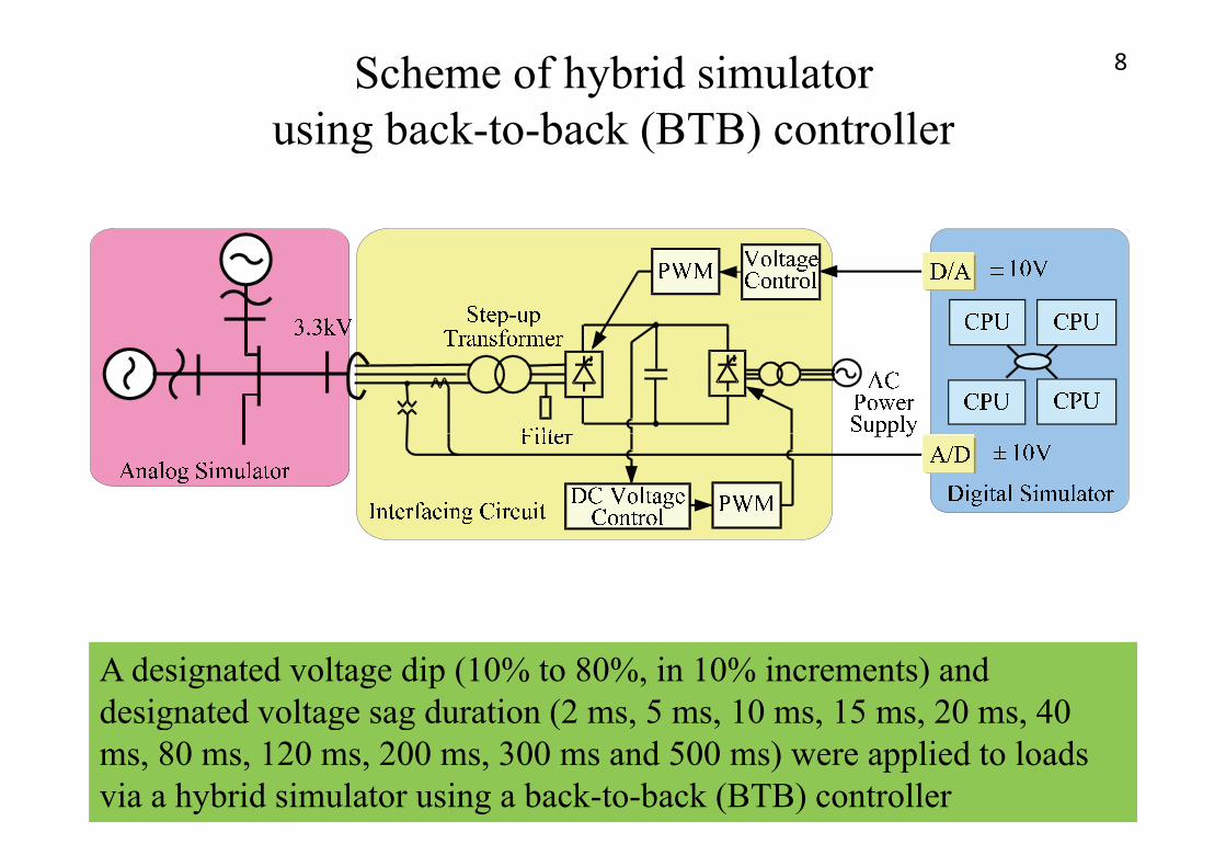
Outline of voltage sag test circuit7
Note: LUTs in group 1 or group 2 were connected to a specified load bus
ETRA requested the Central Research Institute of Electric Power
Note: LUTs in group 1 or group 2 were connected to a specified load bus
ETRA requested the Central Research Institute of Electric Power Industry (CRIEPI) to prepare for more than 40 kinds of load which are widely used in Japan with the aid of committee members in order to y pobtain load self-disconnection characteristics through field tests at the Akagi Testing Center of CRIEPI.
Scheme of hybrid simulator using back-to-back (BTB) controller
8
using back to back (BTB) controller
A designated voltage dip (10% to 80%, in 10% increments) and designated voltage sag duration (2 ms, 5 ms, 10 ms, 15 ms, 20 ms, 40 g g g (ms, 80 ms, 120 ms, 200 ms, 300 ms and 500 ms) were applied to loads via a hybrid simulator using a back-to-back (BTB) controller
Fig.3 Individual load self-disconnection characteristics following a voltage sag
9
characteristics following a voltage sag
(24) (30)(23)
(2)(22)(8) (26)
(20)(19)
(12) (7) (18)(30)
(18)
(14) (2)(22)(8)
(16)
(26)
(4)
(9)(13)(14)(12)
(12) (7)
(17)
(18)
(30)(14)
(15) (10)
(5) (11)
(28)
(6)
(4)
(7) (25)
(18)
(29)
(27)(1)(3)(17) (21)(4)(28)
Some of the loads start to be disconnected from the power system when So e o t e oads sta t to be d sco ected o t e powe syste w ethe voltage sag exceeds 20%. Figure 3 also reveals that no more loads are disconnected when the voltage sag exceeds 70%.
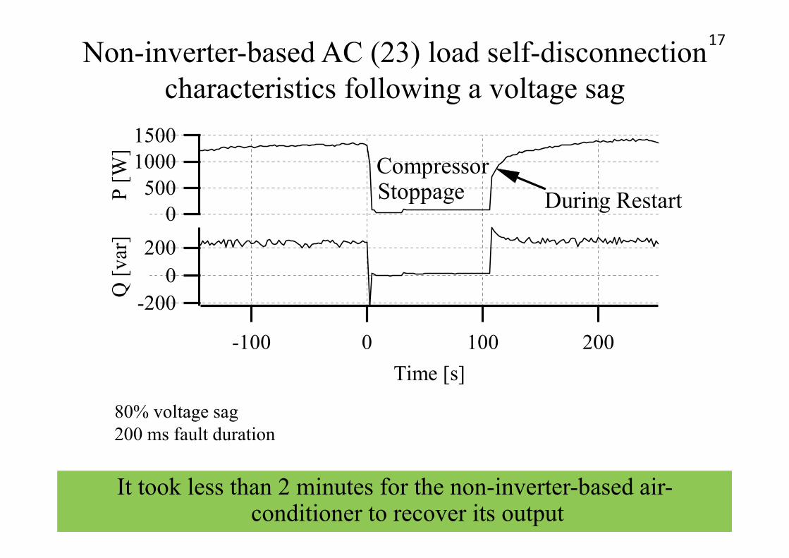
Inverter-based refrigerator (26) load self-disconnection characteristics following a voltage sag
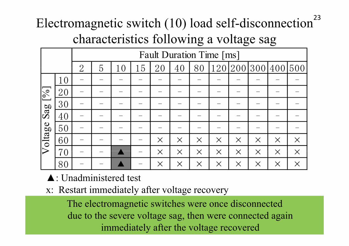
▲: Unadministered testx: Restart immediately after voltage recovery
The electromagnetic switches were once disconnected e e ect o ag et c sw tc es we e o ce d sco ecteddue to the severe voltage sag, then were connected again
immediately after the voltage recovered
Conclusion (Cont’d)24
• It is known that PV systems are often disconnected from the power system due to the voltage sag caused by their ownpower system due to the voltage sag caused by their own protection devices.
• As the use of PV spreads this self-disconnection of PV• As the use of PV spreads, this self-disconnection of PV could affect the transmission line system as well as distribution systemdistribution system.
• Because a voltage sag causes self-disconnection of both PV d l d t th i t t it i i t t t d t dand load at the same instant, it is important to understand
load self-disconnection characteristics more precisely for a d i it t i id d fdynamic security assessment assuming widespread use of PV.
Conclusion (Cont’d)25
• Experiments at CRIEPI in 2010 clarified that some of the l d b di d f h hloads start to be disconnected from the power system when the voltage sag exceeds 20% and that no more loads can be di d h h l d 70%disconnected when the voltage sag exceeds 70%.
• Inverter-based air conditioners and refrigerators tend to be easily disconnected from the power system compared with non-inverter-based air conditioners and refrigerators.
• Non-inverter-based lamps tend to be easily disconnected from the power system compared with inverter-based lamps. p y p p
• If the usage of air-conditioners increases, the amount of self-disconnected loads due to a severe voltage sag willself disconnected loads due to a severe voltage sag will increase.
Conclusion26
Fig. 3 is useful for identifying technical issues concerning various power system phenomena in power systems in thevarious power system phenomena in power systems in the future, and will also contribute to the ongoing CIGRE WG C4.605 “Modelling and aggregation of loads in flexible powerC4.605 Modelling and aggregation of loads in flexible power networks.”
27
Thank you for your attentionThank you for your attention.