12
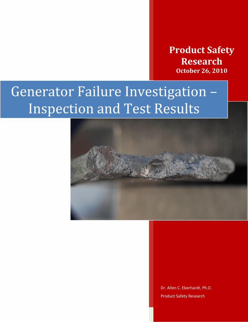
Product Safety Research October 26, 2010 Dr. Allen C. Eberhardt, Ph.D. Product Safety Research Generator Failure Investigation – Inspection and Test Results
Page 0
Product Safety Research
October 26, 2010
Dr. Allen C. Eberhardt, Ph.D.
Product Safety Research
Generator Failure Investigation – Inspection and Test Results

Page 1
Generator Failure Investigation – Inspection and Test Results
Introduction
This report supplements a report of
August 17, 2010, “Generator Failure
Investigation – Amortisseur Winding,”
by Product Safety Research, to include
test data and results of an additional
inspection and investigation conducted
on October 1, 2010. The additional
work utilized a test protocol that was
distributed and reviewed in advance of
the inspection, and subsequently
accepted and followed by the engineers
and investigators in attendance. The
inspection and test protocol is attached
as an appendix to this report.
The protocol specifies additional
measurements made to evaluate the
electrical integrity of the generator major
components, in particular the stator and
rotor insulation and winding resistances,
to evaluate the performance of these
windings with regard not only to shorts,
but for integrity of the insulation.
Typical insulation requirements for
generators of this type are a minimum of
5 meg-ohms. Typical measured values
for these generators are to be greater
than 10 Meg ohms. High values are
required to provide of isolation between
fields, and also to ground.
The actual work performed on October 1
has resulted in data that fulfills, and by
mutual agreement to include additional
measurements, extends the work
outlined within the attached protocol.
An Example of this is the additional
fractured and arc-melted pieces of
amortisseur lamination that were
recovered from within the generator.
These aluminum laminations were
measured to confirm a plate thickness of
0.125 inches. An inspection was also
made at the driven end of the generator,
revealing that the opposing end
lamination of the amortisseur was
similarly damaged.
Background
Prior visual inspections and photographs
of the generator set that were made
following its highway collision on 9-19-
2009, show that the outboard

Page 2
Generator Failure Investigation – Inspection and Test Results
amortisseur winding (damper), and its
attached aluminum end lamination, were
in place and functional prior to
shipment, but were found fractured after
the crash and run-up. Areas of the
aluminum lamination are broken, and
blackened areas are burned and locally
melted as a result of electrical arcing.
The additional tests and results described
herein include the proposed Megger tests
of the insulating properties of the field
and rotor windings. Also tested in this
inspection are the winding resistances,
the rotor and stator concentricity, and the
condition of the six diodes.
Generator Insulation Testing:
Stator
Following the guidelines of the
Marathon Electric Service Procedure [1],
the stator windings were isolated from
all external equipment, including all
electronic components, relays, and the
metering and control transformer leads
H1, H2, H3. The stator leads were tested
in pairs for resistances between phases,
phase-to-phase (P1-P2, P1-P3, P2-P3). A
Megger, model MIT430-TC, was used to
measure multiple DAR (Dielectric
Absorption Ratio) values, recorded using
30 second and 60 second readings, being
more expedient than the ten-minute PI
(Polarization Index) intervals. All stator
windings measured in the Gig-ohm
range, well above the minimum
insulation requirement of 5 Meg-ohms.
Stator temperature was measured at
71oF. The results are as Shown in Table
1.
PHASE: 1-2 1-3 2-3
Test Volts: 1,102 1,102 1,102
Tau 1 G-Ω: 9.0 9.1 9.0
Tau 2 G-Ω: 12.5 12.5 12.5
DAR: 1.38 1.38 1.36
µ-AMP1: 0.12 0.12 0.12
µ-AMP2: 0.19 0.09 0.09
Table 1. Stator insulation resistance
test results Phase-to-Phase between
each of the phases at nominal 1,000V.
Page 3
Generator Failure Investigation – Inspection and Test Results
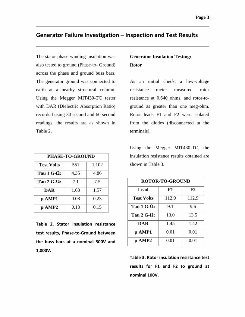
The stator phase winding insulation was
also tested to ground (Phase-to- Ground)
across the phase and ground buss bars.
The generator ground was connected to
earth at a nearby structural column.
Using the Megger MIT430-TC tester
with DAR (Dielectric Absorption Ratio)
recorded using 30 second and 60 second
readings, the results are as shown in
Table 2.
PHASE-TO-GROUND
Test Volts 551 1,102
Tau 1 G-Ω: 4.35 4.86
Tau 2 G-Ω: 7.1 7.5
DAR 1.63 1.57
µ AMP1 0.08 0.23
µ AMP2 0.13 0.15
Table 2. Stator insulation resistance
test results, Phase-to-Ground between
the buss bars at a nominal 500V and
1,000V.
Generator Insulation Testing:
Rotor
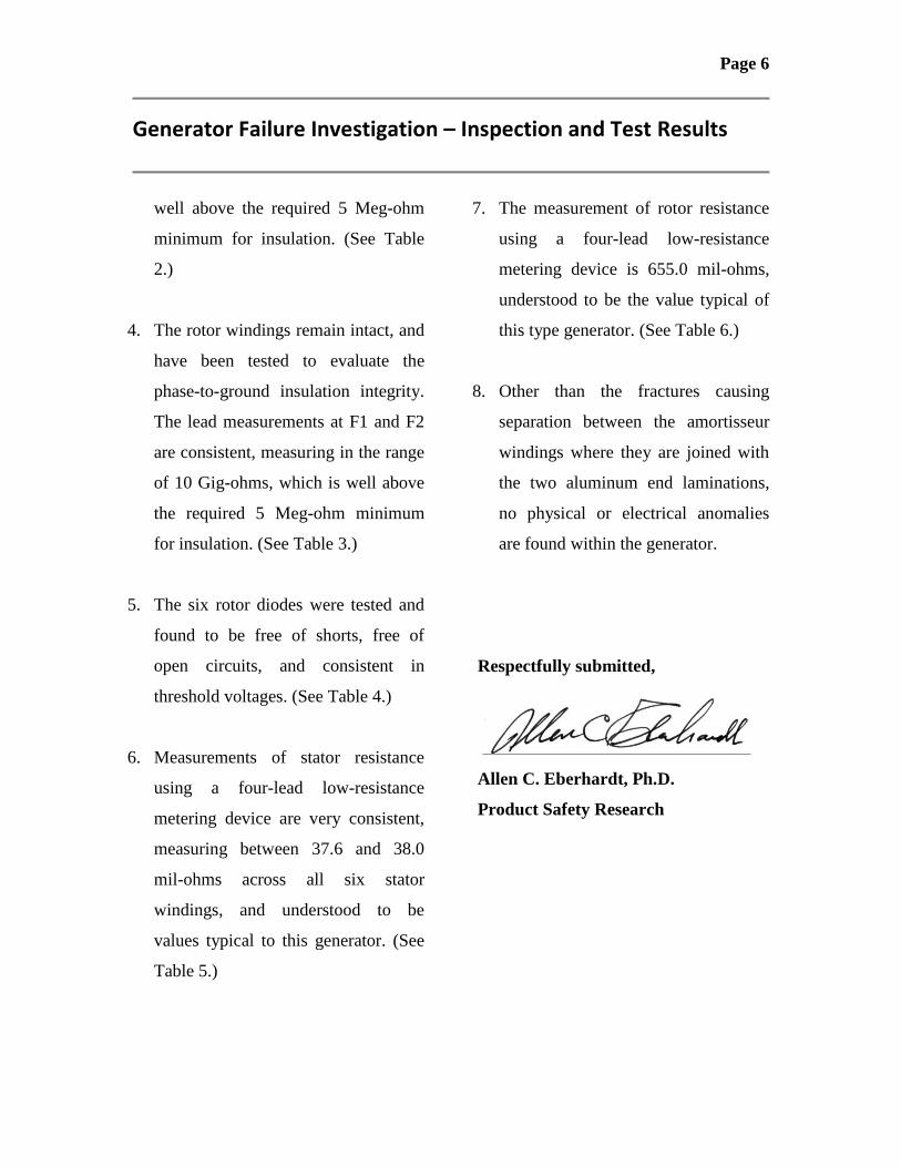
As an initial check, a low-voltage
resistance meter measured rotor
resistance at 0.640 ohms, and rotor-to-
ground as greater than one meg-ohm.
Rotor leads F1 and F2 were isolated
from the diodes (disconnected at the
terminals).
Using the Megger MIT430-TC, the
insulation resistance results obtained are
shown in Table 3.
ROTOR-TO-GROUND
Lead F1 F2
Test Volts 112.9 112.9
Tau 1 G-Ω: 9.1 9.6
Tau 2 G-Ω: 13.0 13.5
DAR 1.45 1.42
µ AMP1 0.01 0.01
µ AMP2 0.01 0.01
Table 3. Rotor insulation resistance test
results for F1 and F2 to ground at
nominal 100V.

Page 4
Generator Failure Investigation – Inspection and Test Results
Rotor - Diode Testing
Diodes were checked using a DC VOM
with a diode voltage capability. Diode
resistances all checked high, and then
low, when lead polarity was swapped,
thus none were open or shorted.
Threshold voltages were measured as
shown in Table 4.
Diode Number 1 2 3
(+) Voltage 0.44 0.43 0.43
Diode Number 4 5 6
(-) Voltage 0.43 0.44 0.42
Table 4. Rotor diode voltage test
results.
Low Resistance Measurements
Stator
A four-lead precision resistance meter
(Instek GOM-801H) was used to check
the field resistances of each of the six
stator field windings. The measurements
were made with the stator at a
temperature of 71oF. Resistances were
measured as shown in Table 5.
Field ID m Ω
T1-T41 37.8
T1-T42 37.8
T2-T51 37.6
T2-T52 37.6
T3-T61 38.0
T3-T62 38.0
Table 5. Stator winding resistances
(mil-Ω) as measured at 71oF.
Low Resistance Measurements
Rotor
The same four-lead precision resistance
meter (Instek GOM-801H) was used to
check the field resistances of the rotor as
a single measurement of the rotor
winding F1-to-F2, with the leads
disconnected from the diodes (windings
not separated). At a temperature of 70oF
the resistance was measured at 0.655
ohms, shown in Table 6.

Page 5
Generator Failure Investigation – Inspection and Test Results
Rotor ID m Ω
F1-F2 655.0
Table 6. Rotor winding resistances (mil-
Ω) as measured at 70oF.
Mechanical Concentricity
As an initial mechanical check of
concentricity, clearances between the
exciter rotor and the exciter stator were
measured at locations where access was
available. The dimensions as recorded
indicate clearances range from a
measured minimum of 0.278 inches to a
measured maximum of 0.302 inches; or
an approximate mean and limit of 0.290
inches, +/- 0.012 inches. Clearance was
maintained with this approximate
concentricity. No marks were observed
that would indicate contact between the
exciter rotor and stator had occurred.
Conclusions:
1. Both the front and rear amortisseur
rotor laminations and windings have
failed. These 0.125-inch aluminum
plates have separated from the
amortisseur windings. The separation
is a result of loads and forces acting
on the generator during the crash
sequence. The lamination fragments
and pieces are evidence of both the
fractures and subsequent catastrophic
arc-melting at startup.
2. The stator windings remain intact,
and have been tested to evaluate
phase-to-phase insulation integrity.
Measurements are consistent between
all stator windings and phases,
measuring in the range of 10 Gig-
ohms, which is well above the
required 5 Meg-ohm minimum for
insulation. (See Table 1.)
3. Insulation testing of the stator
windings between phase and ground
at the buss bars, testing all windings
simultaneously in parallel, measure
in the range of 5 Gig-ohms, which is
Page 6
Generator Failure Investigation – Inspection and Test Results
well above the required 5 Meg-ohm
minimum for insulation. (See Table
2.)
4. The rotor windings remain intact, and
have been tested to evaluate the
phase-to-ground insulation integrity.
The lead measurements at F1 and F2
are consistent, measuring in the range
of 10 Gig-ohms, which is well above
the required 5 Meg-ohm minimum
for insulation. (See Table 3.)
5. The six rotor diodes were tested and
found to be free of shorts, free of
open circuits, and consistent in
threshold voltages. (See Table 4.)
6. Measurements of stator resistance
using a four-lead low-resistance
metering device are very consistent,
measuring between 37.6 and 38.0
mil-ohms across all six stator
windings, and understood to be
values typical to this generator. (See
Table 5.)
7. The measurement of rotor resistance
using a four-lead low-resistance
metering device is 655.0 mil-ohms,
understood to be the value typical of
this type generator. (See Table 6.)
8. Other than the fractures causing
separation between the amortisseur
windings where they are joined with
the two aluminum end laminations,
no physical or electrical anomalies
are found within the generator.
Respectfully submitted,
Allen C. Eberhardt, Ph.D.
Product Safety Research
Page 7
Generator Failure Investigation – Inspection and Test Results
References
1. Marathon Electric–Service Procedure
Generator Insulation Testing,
Marathon Electric, 100 E. Randolph
Street • PO Box 8003, Wausau, WI
54402.
2. Typical Submittal Data, Test Report
No. H-S1000210, Basic Model
1020FDM1210 Marathon Electric,
08/04/08.
Attachments
1. Protocol - Generator Disassembly,
Inspection, and Resistance Testing,
Product Safety Research, 3200 Glen
Royal Road, Suite 102, Raleigh, NC
27617.

Page 1
Protocol
Generator Disassembly, Inspection, and Resistance
Testing
I. STATOR TESTS
A. Main Stator Windings – Insulation Resistance – to Ground
(Meg-Ohms)
1) Remove the conduit box upper-cover and louvered lower-cover
2) Connect a ground cable at the generator ground buss
3) Check to assure that electronic components are disconnected (regulators,
diodes)
4) Disconnect the small leads H1, H2, and H3 at the transformer
5) Check that all stator leads are isolated from ground
6) Record the temperatures of rotor and stator windings
7) Connect the positive megger lead to the stator neutral buss (all stator
windings)
8) Connect the negative megger lead to the generator ground buss
9) Test potential - set the megger test voltage to 500 volts (DC)
10) Record resistance readings R1 and R2 at intervals of T1=30 seconds and
T2=60 seconds, respectively
11) Calculate the Dielectric Absorption Ratio (DAR) = R2/R1
12) If DAR < 1.0, or R2 < 5.0 Meg-ohms, re-test using T1=1 min and T2=10
min, and calculate the Polarization Index (PI) = R2/R1
Note:
Insulation resistance is acceptable if 5.0 Meg-ohms or greater.
Insulation DAR or PI is acceptable if 1.0 or greater.

Page 2
Generator Failure Investigation – Inspection and Test Results
If the insulation resistance is below 5.0 Meg ohms, and/or the DAR is less
than 1.0, the main stator windings may be tested individually, using the
same procedure as above after separating each from the buss.
B. Main Stator Windings – Insulation Resistance – Winding-to-Winding
(Meg-Ohms)
1) Disconnect all six stator leads from the phase buss and from the neutral
buss
2) Connect positive and negative megger leads across every pair
combination
3) Record resistance readings R1 and R2 at intervals of T1=30 seconds and
T2=60 seconds, respectively for each pair
4) Calculate the Dielectric Absorption Ratio (DAR) = R2/R1 for each pair
C. Main Stator Windings – Winding Resistance Testing
(mil-Ohms)
1) With the stator windings disconnected from the buss bars, measure the
resistance across each of the stator windings.
2) Compare resistance values obtained for each of the windings.
3) Realizing that rotor position will influence impedance measurements, as
an option, using an AC impedance meter, measure the impedance across
each of the stator windings (ohms).
Note:
The stator is spattered with aluminum, as the amortisseur laminations
have separated and some amortisseur windings have melted.
Page 3
Generator Failure Investigation – Inspection and Test Results
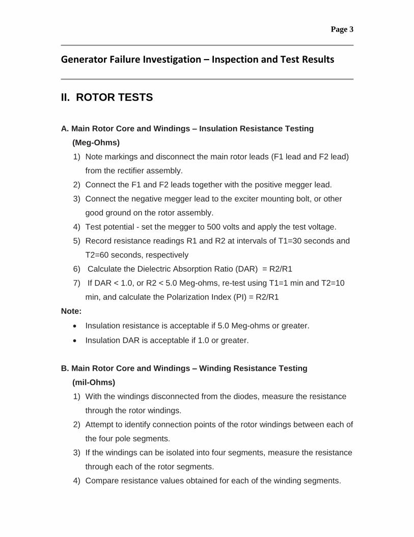
II. ROTOR TESTS
A. Main Rotor Core and Windings – Insulation Resistance Testing
(Meg-Ohms)
1) Note markings and disconnect the main rotor leads (F1 lead and F2 lead)
from the rectifier assembly.
2) Connect the F1 and F2 leads together with the positive megger lead.
3) Connect the negative megger lead to the exciter mounting bolt, or other
good ground on the rotor assembly.
4) Test potential - set the megger to 500 volts and apply the test voltage.
5) Record resistance readings R1 and R2 at intervals of T1=30 seconds and
T2=60 seconds, respectively
6) Calculate the Dielectric Absorption Ratio (DAR) = R2/R1
7) If DAR < 1.0, or R2 < 5.0 Meg-ohms, re-test using T1=1 min and T2=10
min, and calculate the Polarization Index (PI) = R2/R1
Note:
Insulation resistance is acceptable if 5.0 Meg-ohms or greater.
Insulation DAR is acceptable if 1.0 or greater.
B. Main Rotor Core and Windings – Winding Resistance Testing
(mil-Ohms)
1) With the windings disconnected from the diodes, measure the resistance
through the rotor windings.
2) Attempt to identify connection points of the rotor windings between each of
the four pole segments.
3) If the windings can be isolated into four segments, measure the resistance
through each of the rotor segments.
4) Compare resistance values obtained for each of the winding segments.

Page 4
Generator Failure Investigation – Inspection and Test Results
5) Realizing that rotor position will influence impedance measurements, as
an option, using an AC impedance meter, measure the impedance across
each of the four rotor winding segments (ohms).
6) Test for shorted turns by comparing readings of the four segments for
agreement to within a few percent.
Note:
Impedance is affected by rotor position within the stator.
References:
1. MagnaPower - Installation, Operation, and Maintenance Manual
2. Marathon Electric - Service Procedure - Generator Insulation Testing
3. IEEE Std 43-2000 Recommended Practice for Testing Insulation
Resistance of Rotating Machinery


