12
INSTRUCTION MANUAL OF THE GPS SENSOR MGPS Published by JETI model s.r.o 3rd May 2010

INSTRUCTION MANUAL
OF THE GPS SENSOR
MGPS
Published by JETI model s.r.o 3rd May 2010

Instruction Manual: Sensor MGPS
-2-
CONTENTS
1. PREFACE ........................................................................................................................................... 3
2. DESCRIPTION .................................................................................................................................... 3
3. CONNECTION .................................................................................................................................... 4
3.1 CONTROL INPUT .......................................................................................................................................................................... 4 3.1.1 V-Cable ............................................................................................................................................................................ 4 3.1.2 Duplication of a Duplex Receiver Channel ....................................................................................................................... 4
3.2 CONNECTION OF THE MGPS TO THE JETIBOX .................................................................................................................................. 5 3.3 CONNECTION OF THE MGPS TO THE DUPLEX RECEIVER ..................................................................................................................... 5 3.4 CONNECTION OF THE MGPS TO THE DUPLEX RECEIVER VIA AN EXPANDER ............................................................................................ 5
4. DATA RECORDING ............................................................................................................................. 6
5. MGPS MENU ..................................................................................................................................... 6
5.1 ACTUAL VALUE ........................................................................................................................................................................ 6 5.2 MIN / MAX ............................................................................................................................................................................... 7 5.3 SETTING ................................................................................................................................................................................... 8 5.4 ALARMS ................................................................................................................................................................................... 9 5.5 GPS DATA ................................................................................................................................................................................ 9 5.6 SERVICE ................................................................................................................................................................................... 9
6. SOFTWARE AND CONNECTION TO THE PC ....................................................................................... 10
7. INSTALLATION ................................................................................................................................ 10
8. TECHNICAL DATA ............................................................................................................................ 11
9. WARRANTY ..................................................................................................................................... 11
10. MGPS MENU DIAGRAM ................................................................................................................. 12
Instruction Manual: Sensor MGPS
-3-
1. Preface
Exact informations about the altitude and distance of a model in space are extremely important
guidance elements for the pilot who is remote controlling the model. Thanks to the GPS satellite
positioning system the MGPS sensor defines the exact model position and calculates speed, altitude
and distance from the point of origin, furthermore the course, azimuth and the total covered distance.
In order to be able to record the measured data the MGPS sensor is equipped with a memory for
approximately 18 hours of uninterrupted data recording with a numerosity of one record per second
(8 MB MGPS version). For a simple analysis of measured data the sensor keeps informations of
minima and maxima which can be browsed with the aid of the JETIBOX. A more detailed analysis of
measured data can be achieved by copying data from the sensor to a PC and map depicted trajectories
or carry out other analysis modes. With the aid of the wireless DUPLEX system actual informations
of the MGPS sensor can be transmitted and depicted in real time by the JETIBOX terminal.
2. Description
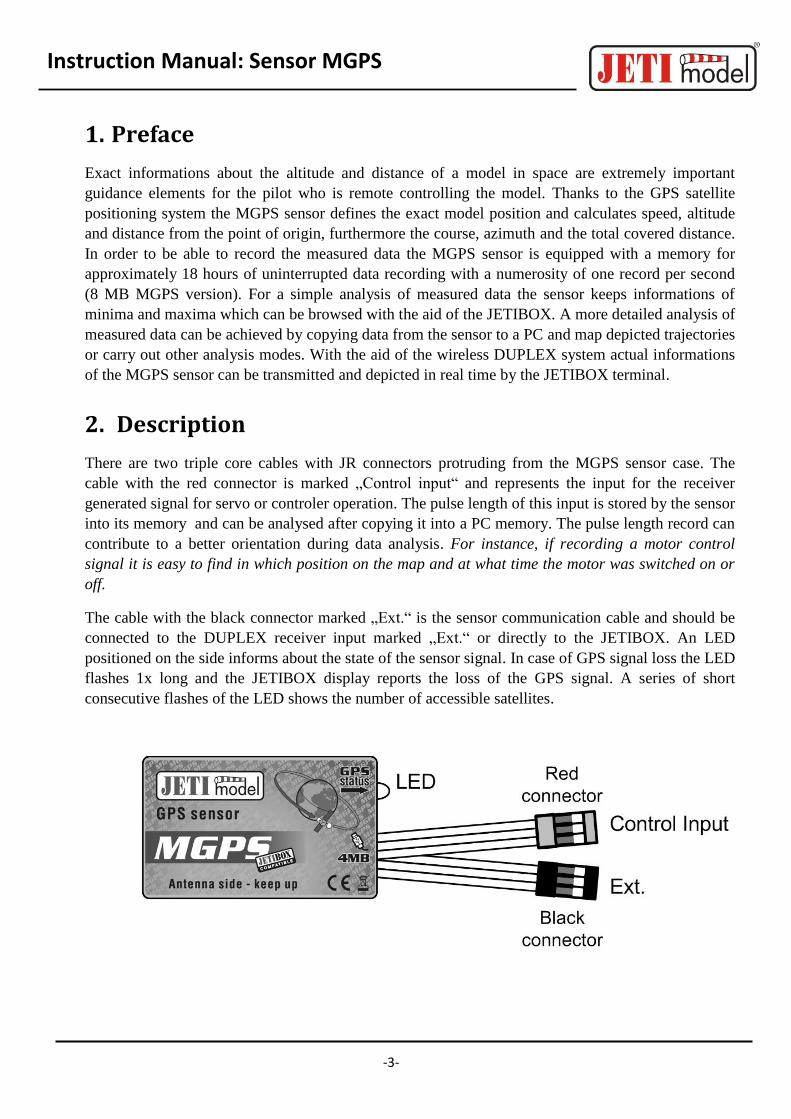
There are two triple core cables with JR connectors protruding from the MGPS sensor case. The
cable with the red connector is marked „Control input“ and represents the input for the receiver
generated signal for servo or controler operation. The pulse length of this input is stored by the sensor
into its memory and can be analysed after copying it into a PC memory. The pulse length record can
contribute to a better orientation during data analysis. For instance, if recording a motor control
signal it is easy to find in which position on the map and at what time the motor was switched on or
off.
The cable with the black connector marked „Ext.“ is the sensor communication cable and should be
connected to the DUPLEX receiver input marked „Ext.“ or directly to the JETIBOX. An LED
positioned on the side informs about the state of the sensor signal. In case of GPS signal loss the LED
flashes 1x long and the JETIBOX display reports the loss of the GPS signal. A series of short
consecutive flashes of the LED shows the number of accessible satellites.
Instruction Manual: Sensor MGPS
-4-
3. Connection
3.1 Control Input
If we want the sensor MGPS to record pulse lengths it is advisable to use one of the following
methods.
3.1.1 V-Cable
Connect the V-cable to the receiver, one of the two ends for example to the regulator,
servo etc. and the other end to the MGPS input marked as Control input.
3.1.2 Duplication of a Duplex Receiver Channel
The Duplex receiver shall be adjusted so that it generates a copy of the requested channel
at a free exit. Connect one exit for example to the regulator or servo and the Control input
of the MGPS sensor to the duplicated exit.
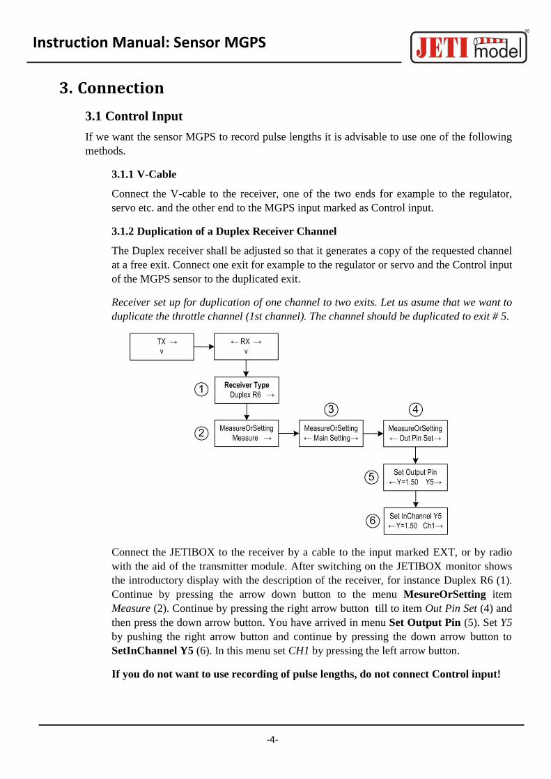
Receiver set up for duplication of one channel to two exits. Let us asume that we want to
duplicate the throttle channel (1st channel). The channel should be duplicated to exit # 5.
Connect the JETIBOX to the receiver by a cable to the input marked EXT, or by radio
with the aid of the transmitter module. After switching on the JETIBOX monitor shows
the introductory display with the description of the receiver, for instance Duplex R6 (1).
Continue by pressing the arrow down button to the menu MesureOrSetting item
Measure (2). Continue by pressing the right arrow button till to item Out Pin Set (4) and
then press the down arrow button. You have arrived in menu Set Output Pin (5). Set Y5
by pushing the right arrow button and continue by pressing the down arrow button to
SetInChannel Y5 (6). In this menu set CH1 by pressing the left arrow button.
If you do not want to use recording of pulse lengths, do not connect Control input!

Instruction Manual: Sensor MGPS
-5-
3.2 Connection of the MGPS to the JETIBOX
This connection requires the application of a voltage source of 3,5 to 8,4V, for instance a
receiver battery. The triple core MPGS sensor cable with black JR connector must be
connected to the JETIBOX (socket marked Impuls, + - ). When using the JETIBOX mini
apply the input socket marked „Ext.“ This connection does not allow generation of acoustic
alerts due to the absence of the signal buzzer, which is part of the in this instance not connected
transmitter module. Alerts are depicted on the JETIBOX display only.
3.3 Connection of the MGPS to the DUPLEX receiver
In this case only one sensor with power supply via the receiver can be connected. The triple
core MGPS sensor cable with black JR connector must be connected to the DUPLEX
receiver (to the input marked EXT.). Connection of Control input see chapter 3.1.
3.4 Connection of the MGPS to the DUPLEX receiver via an Expander
Using this configuration it is possible to process data from several sensors simultaneously with
power supply via the expander. The triple core MPGS sensor cable with black JR connector
must be connected to one of the Expander inputs. Connection of Control input see chapter
3.1.

Instruction Manual: Sensor MGPS
-6-
4. Data Recording
The MGPS sensor is manufactured with 4 or 8MB high capacity memories for data recording. The
MGPS sensor with 4MB memory offers a data storage capacity of 32 768 savings or a capacity of
1024 records corresponding approximately to nine hours of uninterrupted recording with the
numerosity of 1x per second savings or 1024 switching on operations. The storage numerosity can be
set up in the menu „SETTING->Record Period“. The MGPS can be read out and analysed by a
computer. When switched on the sensor starts automatically storing data as long as the signal
of the GPS satellites is of sufficient quality. That means that the number of available GPS satellites
must be at least 5 or more. The informations in the sensor memory are arranged into entries
(Records), which are supplied with identification numbers (ID) according to the succession of
formation. After every switching on and fulfillment of the condition of a sufficiently good signal the
sensor automatically creates a new record file and starts to store the measured data into it. If
accidentally the complete memory becomes filled the data starts overwriting oldest records and in the
menu „ACTUAL VAL -> Record ID Mem Usage“ the utilization of the memory will be indicated by
hundred percent. For better clarity of records we recommend to store the memory after it has been
filled up into a PC and then delete it by „SETTING->Erase GPS log“.
5. MGPS Menu
Parameter set up and data readout is carried out by the JETIBOX. After connection to the MGPS
sensor the introductory display shows the identification of the equipment and three assigned positions
for the portrayal of actual data. In the given positions there can be adjusted up to five combinations of
quantities like: speed, altitude, distance and covered path. By pressing the right arrow button in
the introductory display for a fairly long time renders it possible to arrange data as shown in
the following picture.
By pressing D (down arrow) of the JETIBOX you will enter into the MGPS menu.
5.1 ACTUAL VALUE
MGPS MENU: Actual Value – by pressing button D (down arrow) you will select the display
of actual measured values

Instruction Manual: Sensor MGPS
-7-
Distance/Speed – shows the distance of the model from the point of origin (ORIGIN) and its
actual speed.
Trip/Speed – shows the covered path from the last zeroing/switching on point and the actual
speed.
Course/Dist/Alt – shows the actual model heading, distance and altitude from the origin.
The heading (course) is the angle between the trajectory of model motion and the direction to
the north pole. This information may be extremely important if you want to know the direction
of model motion.
Azimuth/Dist/Alt – shows the actual model azimuth, distance and altitude in relation to the
origin.
Azimuth is the angle with its vertex in the point of origin (ORIGIN) formed between the model
and the north pole. The information about the azimuth may be helpful in case of a model loss.
The pilot owns informations about the model position.
Date/Time – depiction of date and exact time.
GPS Status – depiction of the number of accessible GPS satellites and of the input voltage
level.
Record ID and Mem Usage – succession of records and memory utilization. After switching on
collection of data starts in a new record, see chapter Chyba! Nenalezen zdroj odkazů..
5.2 MIN / MAX
MGPS MENU: MIN / MAX – by pressing button D (arrow down) you select record depictions
of altitude extremes, distance extremes and speed extremes which occurred during operation.
The record of extremes is deleted automatically or can be deleted manually in the menu
Instruction Manual: Sensor MGPS
-8-
Setting - Erase Min/Max. If the senzor will be connected to a voltage supply under fulfillment
of conditions shown below, automatic deletion of minimum and maximum values will occur.
The number of accessible GPS satellites is at least 5 or more,
The actual speed will for the duration of five seconds be higher than 10km/h.
In case of sensor switching on without fulfilling the conditions mentioned above, minimum and
maximum values of the preceding sensor operation will be depicted.
Altitude Min/Max – shows minimum and maximum altitude.
Maximal Distance – shows maximum distance of the point of origin (ORIGIN).
Maximal Velocity – shows maximum speed.
Last trip – shows value of covered path before sensor switching off.
5.3 SETTING
MGPS MENU: SETTING – by pressing button D (arrow down) a change to the basic setting of
the MGPS sensor will be carried out.
StartNewRecord – by simultaneous pressing of arrows R and L (right and left) a new record in
the memory is created and storing of new data gets started.
Set Origin – by simultaneous pressing of arrows R and L (right and left) a new origin is
created and simultaneously minimum and maximum values are deleted. Adjust the origin
only if there are at least 5 or more GPS satellites accessible. Origin set up is very important for
correct measurements of actual sensor values like distance and altitude. These values are
derived from the origin.
After arrival at the flying field switch on the MGPS, wait until reception of GPS satellites
develops good quality and set up the origin. The sensor keeps the information of the origin in
its memory, therefore you do not have to set it everytime you are switching the sensor on as
long as you stay within the flying field region.
Erase Min/Max – by simultaneous pressing of arrows R and L (right and left) minimum and
maximum values are deleted.
Erase GPS log – by simultaneous pressing of arrows R and L (right and left) the complete
sensor memory becomes erased.
Record Period – numerosity of storing measured data into memory. With the aid of this set up
you may lengthen or shorten the recording time.
Altitude Alarm Code – setting of the Morsealphabet letter which will represent exceeding of the
adjusted altitude margin by an acoustical alert tone of the transmitter module DUPLEX Tx.
Distance Alarm Code – setting of the Morsealphabet letter which will represent exceeding of
the adjusted distance margin by an acoustical alert tone of the transmitter module DUPLEX Tx.
Instruction Manual: Sensor MGPS
-9-
Velocity Alarm Code – setting of the Morsealphabet letter which will represent exceeding of the
adjusted speed margin by an acoustical alert tone of the transmitter module DUPLEX Tx.
Velocity unit – setting of the unit of measured velocity.
Set Timezone – setting of the time shift in relation to the Greenwich prime meridian.
5.4 ALARMS
MGPS MENU: ALARMS – by pressing pushbutton D (arrow down) you change to the setting
of individual alerts. If one of the set parameter margins will be violated, the JETIBOX will
show in the second line of its introductory display in turns the original picture and the
corresponding alert as well as the transmitter module siren will emit the corresponding
sound alert. The first tone is a cautionary sound and the second one represents the
Morsealphabet letter of the corresponding alert. As long as the alarm is set to OFF this alert
will be switched off.
Altitude Alarm – setting the value of the altitude alert. If the measured altitude oversteps the set
value the altitude alert will be activated.
Distance Alarm – setting the value of the distance alert. If the measured distance oversteps the
set value the distance alert will be activated.
Speed Alarm – setting the value of the speed alert. If the measured speed oversteps the set value
the speed alert will be activated.
5.5 GPS DATA
MGPS MENU: GPS DATA – by pressing button D (arrow down) you will change to the
depiction of actual informations about coordinates and altitude above sea level.
GPS Latitude – coordinates of terrestrial latitude of the actual position.
GPS Longitude - coordinates of terrestrial longitude of the actual position.
GPS Altitude – altitude above sea level of the actual position.
GPS Timestamp – exact time at the zero meridian in the format: HHMMSS.SS.
5.6 SERVICE
MGPS MENU: SERVICE – by pressing button D (arrow down) you will change to depiction of
the firmware version and to renewal of the sensor default setting.
Factory Defaults – by simultaneous pressing of arrows R and L (right and left) the factory
settings of the MGPS are loaded.
MGPS v. xx.xx ID xxxxx:xxxxx – product marking with firmware version and series number
(ID).

Instruction Manual: Sensor MGPS
-10-
6. Software and Connection to the PC
The USBa adapter is used for connection of the MGPS to the PC and for data transfer. The USBa
adapter is connected to the USB port of a computer (1) and the input Ext. of the MGPS sensor
is plugged into the adapter (2). The equipment gets its power supply via the computer, there are no
other power sources necessary.
The last step consists of the service program start and data storing in the PC. The MGPS service
software is available on the manufacturer internet pages www.jetimodel.com in the technical support
section.
7. Installation
The MGPS sensor is equipped with an GPS antenna, it is therefore important to place the sensor in a
suitable position in the model. It must lie horizontal with the sticker turned upwards to the sky and
must not be screened by any conductive materials. The GPS signal passes through non conductive
materials like: plastic, wood, but does not pass through conductive materials like: carbon, metals.

Instruction Manual: Sensor MGPS
-11-
8. Technical Data
Technical Data MGPS 4MB MGPS 8MB
Dimensions [mm] 50x30x12,5 50x30x12,5
Weight (incl. cables) 24g 24g
Memory 32768 savings or 1024 recordings
65536 savings or 2048 recordings
Recording time * 9h 6min 18h 12min
Operating temperature -20 till 85°C -20 till 85°C
Supply voltage 3,5 - 8,4 V 3,5 - 8,4 V
Mean current consumpt. 40 mA 40 mA
Maximum consumption 100 mA 100 mA
* - with a saving numerosity of one saving per second
9. Warranty
For the product we grant a warranty of 24 months from the day of purchase under the assumption
that it has been operated in conformity with these instructions at recommended voltages and that it
has not been damaged mechanically. Warranty and post warranty service is provided by the
manufacturer.
We wish you sucessful flying with the products of: JETI model s.r.o. Příbor, www.jetimodel.cz
Instruction Manual: Sensor MGPS
-12-
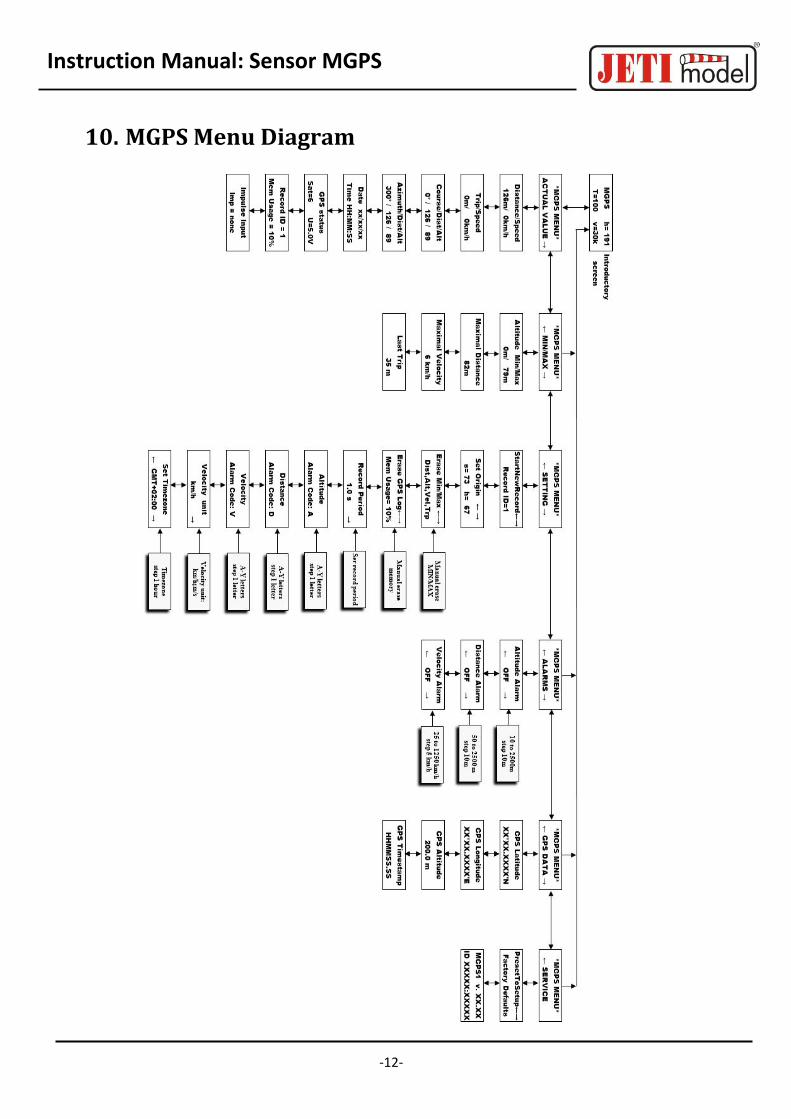
10. MGPS Menu Diagram


