19
1 IEEE 802.3bn Phoenix, AZ January 23-25, 2012 OFDM Numerology Christian Pietsch (Qualcomm)
1 IEEE 802.3bn Phoenix, AZ January 23-25, 2012 1 IEEE 802.3bn Phoenix, AZ January 23-25, 2012
OFDM Numerology
Christian Pietsch (Qualcomm)
2 IEEE 802.3bn Phoenix, AZ January 23-25, 2012
Outline
Downstream Numerology Overview
Frame Structure and Pilot Structure
CP Impact Analysis
Modulation and FEC Proposal
Time Domain Interleaving
3 IEEE 802.3bn Phoenix, AZ January 23-25, 2012
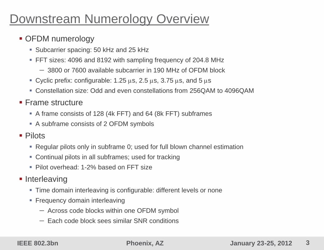
Downstream Numerology Overview
OFDM numerology
Subcarrier spacing: 50 kHz and 25 kHz
FFT sizes: 4096 and 8192 with sampling frequency of 204.8 MHz
– 3800 or 7600 available subcarrier in 190 MHz of OFDM block
Cyclic prefix: configurable: 1.25 s, 2.5 s, 3.75 s, and 5 s
Constellation size: Odd and even constellations from 256QAM to 4096QAM
Frame structure
A frame consists of 128 (4k FFT) and 64 (8k FFT) subframes
A subframe consists of 2 OFDM symbols
Pilots
Regular pilots only in subframe 0; used for full blown channel estimation
Continual pilots in all subframes; used for tracking
Pilot overhead: 1-2% based on FFT size
Interleaving
Time domain interleaving is configurable: different levels or none
Frequency domain interleaving
– Across code blocks within one OFDM symbol
– Each code block sees similar SNR conditions
4 IEEE 802.3bn Phoenix, AZ January 23-25, 2012
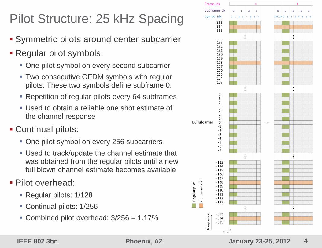
Pilot Structure: 25 kHz Spacing
Symmetric pilots around center subcarrier
Regular pilot symbols:
One pilot symbol on every second subcarrier
Two consecutive OFDM symbols with regular pilots. These two symbols define subframe 0.
Repetition of regular pilots every 64 subframes
Used to obtain a reliable one shot estimate of the channel response
Continual pilots:
One pilot symbol on every 256 subcarriers
Used to track/update the channel estimate that was obtained from the regular pilots until a new full blown channel estimate becomes available
Pilot overhead:
Regular pilots: 1/128
Continual pilots: 1/256
Combined pilot overhead: 3/256 = 1.17%
385384383
133132131130129128127126125124123
76543210-1-2-3-4-5-6-7
-123-124-125-126-127-128-129-130-131-132-133
-383-384-385
Time
Fre
qu
en
cy
DC subcarrier
Frame idx 0 1
Symbol idx 0 1 2 3 4 5 6 7 126 127 0 1 2 3 4 5 6 7
Subframe idx 0 1 2 3 63 0 1 2 3
Re
gula
r p
ilot
Co
nti
nu
al P
ilot
5 IEEE 802.3bn Phoenix, AZ January 23-25, 2012
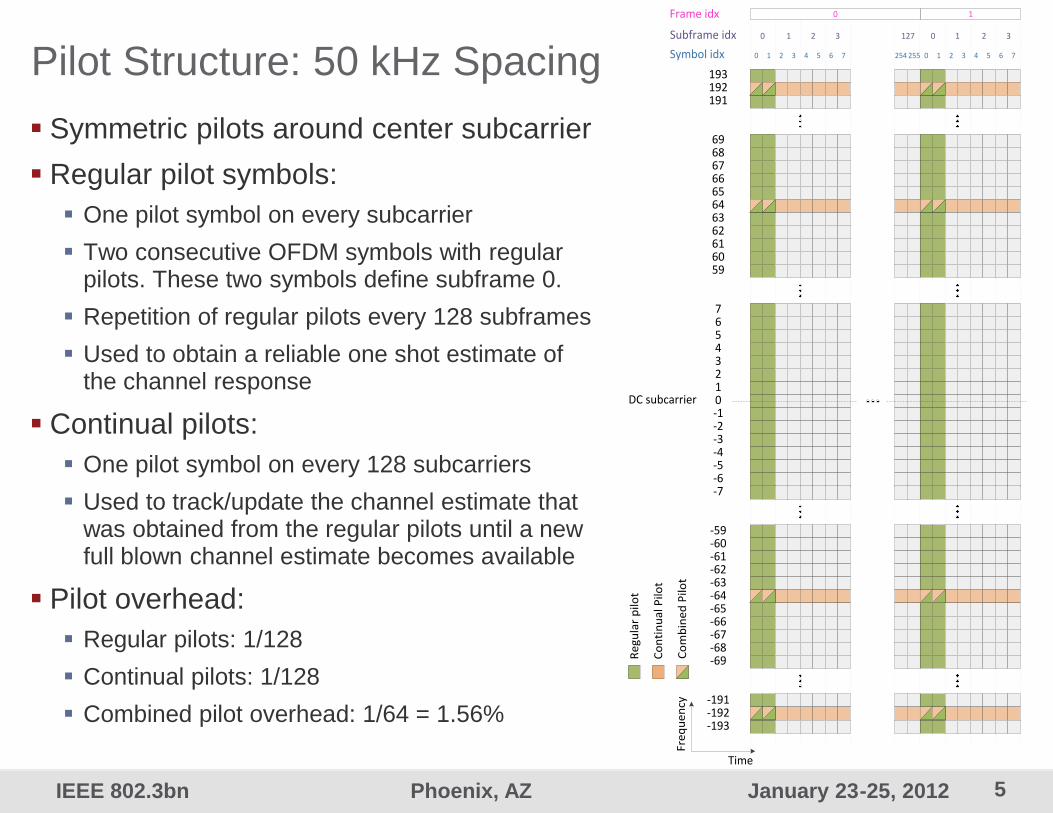
Pilot Structure: 50 kHz Spacing 193192191
6968676665646362616059
76543210-1-2-3-4-5-6-7
-59-60-61-62-63-64-65-66-67-68-69
-191-192-193
Time
Fre
qu
en
cy
DC subcarrier
Re
gula
r p
ilot
Co
nti
nu
al P
ilot
Co
mb
ine
d P
ilot
Frame idx 0 1
Symbol idx 0 1 2 3 4 5 6 7 254 255 0 1 2 3 4 5 6 7
Subframe idx 0 1 2 3 127 0 1 2 3
Symmetric pilots around center subcarrier
Regular pilot symbols:
One pilot symbol on every subcarrier
Two consecutive OFDM symbols with regular pilots. These two symbols define subframe 0.
Repetition of regular pilots every 128 subframes
Used to obtain a reliable one shot estimate of the channel response
Continual pilots:
One pilot symbol on every 128 subcarriers
Used to track/update the channel estimate that was obtained from the regular pilots until a new full blown channel estimate becomes available
Pilot overhead:
Regular pilots: 1/128
Continual pilots: 1/128
Combined pilot overhead: 1/64 = 1.56%
6 IEEE 802.3bn Phoenix, AZ January 23-25, 2012
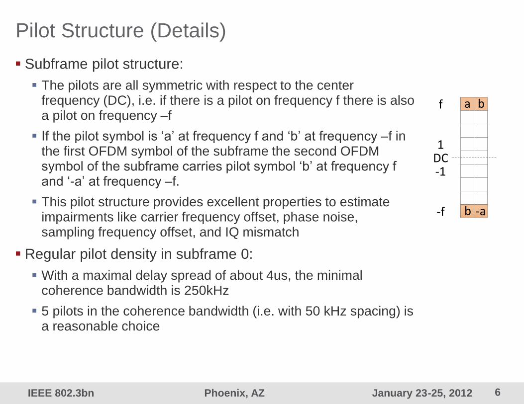
Pilot Structure (Details)
Subframe pilot structure:
The pilots are all symmetric with respect to the center frequency (DC), i.e. if there is a pilot on frequency f there is also a pilot on frequency –f
If the pilot symbol is ‘a’ at frequency f and ‘b’ at frequency –f in the first OFDM symbol of the subframe the second OFDM symbol of the subframe carries pilot symbol ‘b’ at frequency f and ‘-a’ at frequency –f.
This pilot structure provides excellent properties to estimate impairments like carrier frequency offset, phase noise, sampling frequency offset, and IQ mismatch
Regular pilot density in subframe 0:
With a maximal delay spread of about 4us, the minimal coherence bandwidth is 250kHz
5 pilots in the coherence bandwidth (i.e. with 50 kHz spacing) is a reasonable choice
a b
b
f
1DC-1
-f -a

7 IEEE 802.3bn Phoenix, AZ January 23-25, 2012
ReDeSign Channel Models Case 1 and Case 2
ReDeSign Channel Model Case 1
ReDeSign Channel Model Case 2
8 IEEE 802.3bn Phoenix, AZ January 23-25, 2012
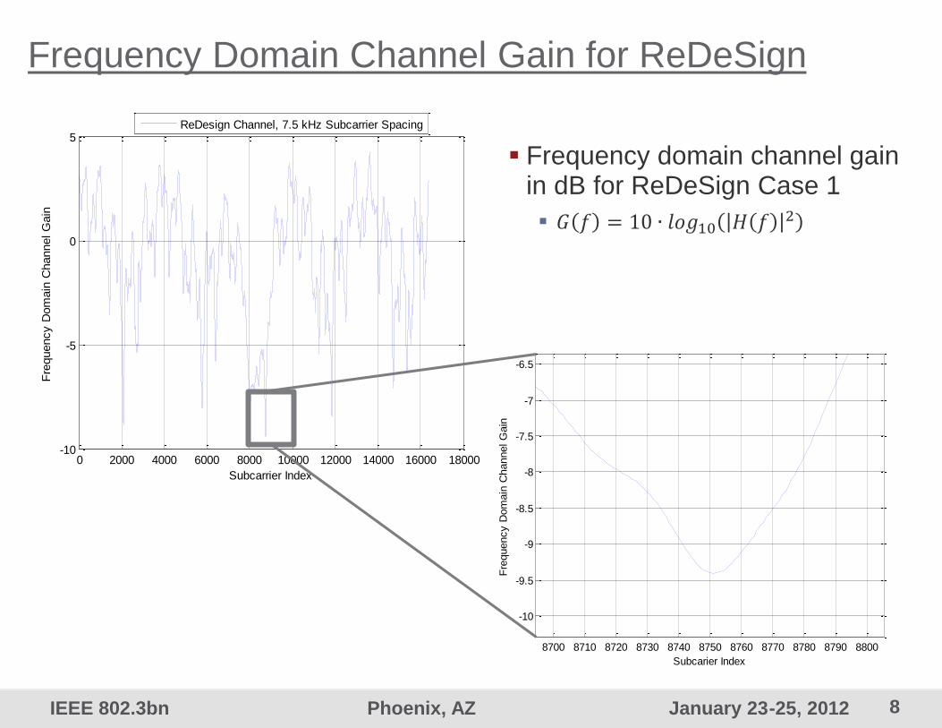
Frequency Domain Channel Gain for ReDeSign
Frequency domain channel gain in dB for ReDeSign Case 1
𝐺 𝑓 = 10 ∙ 𝑙𝑜𝑔10 𝐻 𝑓 2
0 2000 4000 6000 8000 10000 12000 14000 16000 18000-10
-5
0
5
Subcarrier Index
Fre
quency D
om
ain
Channel G
ain
ReDesign Channel, 7.5 kHz Subcarrier Spacing
8700 8710 8720 8730 8740 8750 8760 8770 8780 8790 8800
-10
-9.5
-9
-8.5
-8
-7.5
-7
-6.5
Subcarier Index
Fre
quency D
om
ain
Channel G
ain
9 IEEE 802.3bn Phoenix, AZ January 23-25, 2012
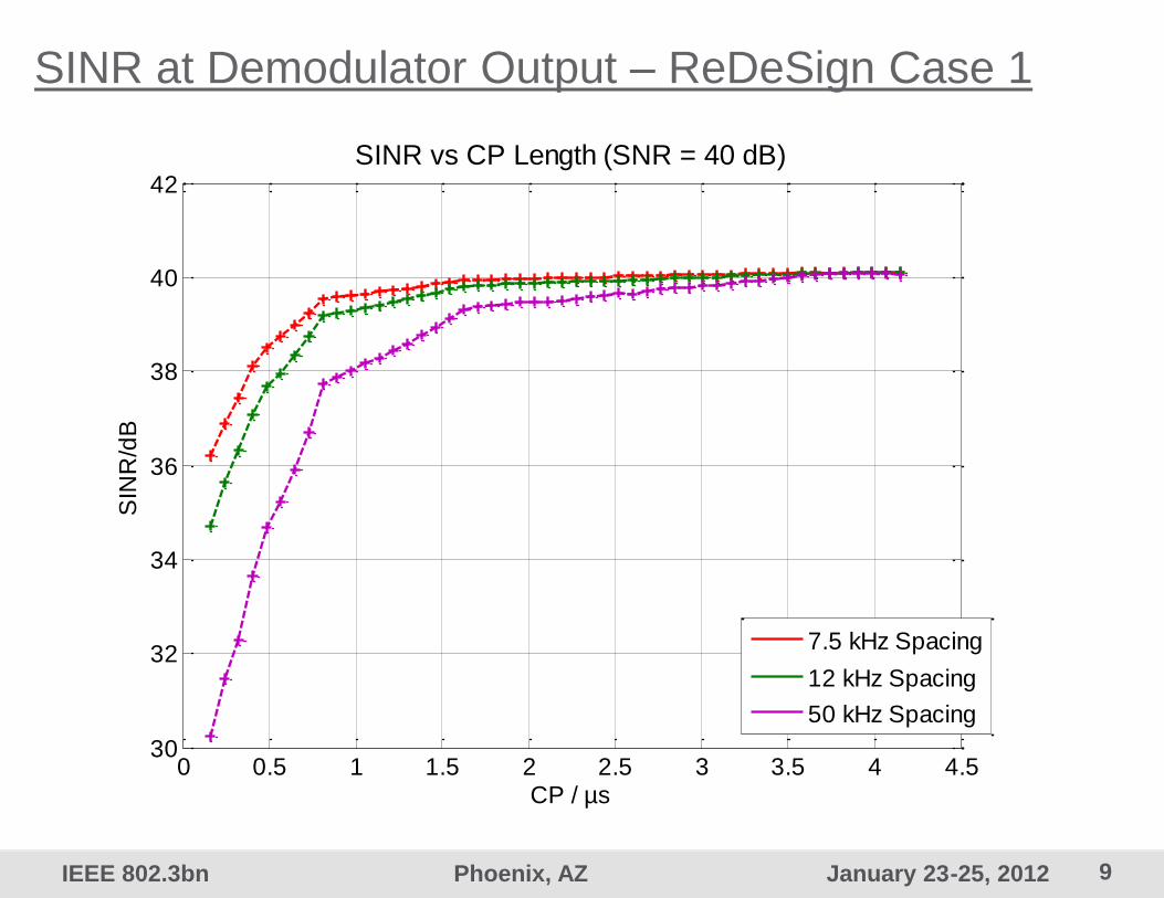
SINR at Demodulator Output – ReDeSign Case 1
0 0.5 1 1.5 2 2.5 3 3.5 4 4.530
32
34
36
38
40
42
SIN
R/d
B
CP / µs
SINR vs CP Length (SNR = 40 dB)
7.5 kHz Spacing
12 kHz Spacing
50 kHz Spacing

10 IEEE 802.3bn Phoenix, AZ January 23-25, 2012
0 0.5 1 1.5 2 2.5 3 3.5 4 4.526
28
30
32
34
36
38
40
SIN
R/d
B
CP / µs
SINR vs CP Length (SNR = 40 dB)
7.5 kHz Spacing
12 kHz Spacing
50 kHz Spacing
SINR at Demodulator Output – ReDeSign Case 2

11 IEEE 802.3bn Phoenix, AZ January 23-25, 2012
Modulation and Forward Error Correction
QAM Modulation
Preferred modulation alphabets are (16QAM), (32QAM), (64QAM), (128QAM), 256QAM, 512QAM, 1024QAM, 2048QAM, and 4096QAM
Downstream proposal: DVB-C2 codes
Common MCS per group of users enables the aggregation of Ethernet frames dedicated to multiple users of such a group into a single code word. (equivalent to multiple profiles approach)
It is anticipated that longer codes are more efficient when users are grouped
Applying the DVB-C2 LDPC and BCH codes is the preferred approach since they are well known and fully specified
Upstream proposal: IEEE 802.11n LDPC codes
The IEEE LDPC codes support short code word lengths that fit well with OFDMA
Analysis for AWGN and time dispersive channels has shown that performance is superior compared to RS codes of similar length
Code word lengths are optimized for Ethernet frame lengths
12 IEEE 802.3bn Phoenix, AZ January 23-25, 2012
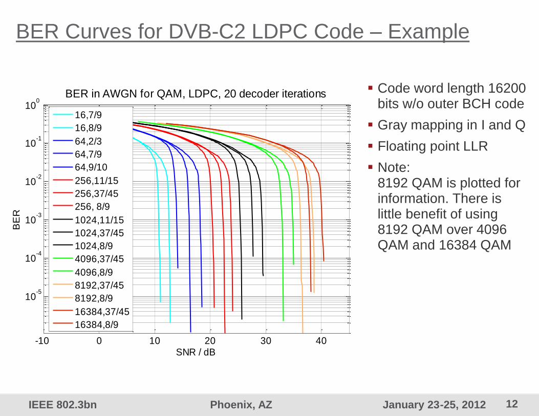
BER Curves for DVB-C2 LDPC Code – Example
Code word length 16200 bits w/o outer BCH code
Gray mapping in I and Q
Floating point LLR
Note: 8192 QAM is plotted for information. There is little benefit of using 8192 QAM over 4096 QAM and 16384 QAM
-10 0 10 20 30 40
10-5
10-4
10-3
10-2
10-1
100
BER in AWGN for QAM, LDPC, 20 decoder iterations
SNR / dB
BE
R
16,7/9
16,8/9
64,2/3
64,7/9
64,9/10
256,11/15
256,37/45
256, 8/9
1024,11/15
1024,37/45
1024,8/9
4096,37/45
4096,8/9
8192,37/45
8192,8/9
16384,37/45
16384,8/9

13 IEEE 802.3bn Phoenix, AZ January 23-25, 2012
Direct Convolutional Time Interleaving
Convolutional interleaving is applied at subcarrier level
Convolutional interleaving delays each subcarrier in time
For a time-invariant channel, interleaving across MCS profiles is possible
But: Delay and memory consumption are excessive for direct interleaving
Required number of memory elements: 4k (4k – 1) / 2 = 8386560
Burst Error
Channel
Time
Fre
quency
Interleaving De-Interleaving
MCS profiles
1
2
FFT Size -
1
1
2
FFT -1
IFF
T
FF
T
Memory elements Memory elements
14 IEEE 802.3bn Phoenix, AZ January 23-25, 2012
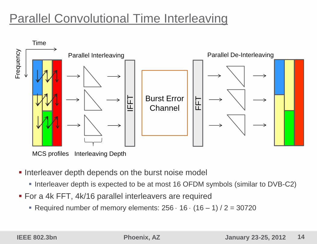
Parallel Convolutional Time Interleaving
Interleaver depth depends on the burst noise model
Interleaver depth is expected to be at most 16 OFDM symbols (similar to DVB-C2)
For a 4k FFT, 4k/16 parallel interleavers are required
Required number of memory elements: 256 16 (16 – 1) / 2 = 30720
Burst Error
Channel
Time
Fre
quency
Interleaving Depth
Parallel De-Interleaving
MCS profiles
Parallel Interleaving
IFF
T
FF
T

15 IEEE 802.3bn Phoenix, AZ January 23-25, 2012
Parallel Convolutional Interleaving Structure E
rroneous c
ode s
ym
bols
in fre
quency d
om
ain
Synchronous Burst Noise
w/o Time Interleaving Synchronous Burst Noise w/
Time Interleaving Depth D = 6
Asynchronous Burst Noise w/
Time Interleaving Depth D = 6
D-1
err
or
free c
ode s
ym
bols
D-2
err
or
free c
ode s
ym
bols
OFDM Symbols OFDM Symbols OFDM Symbols
16 IEEE 802.3bn Phoenix, AZ January 23-25, 2012
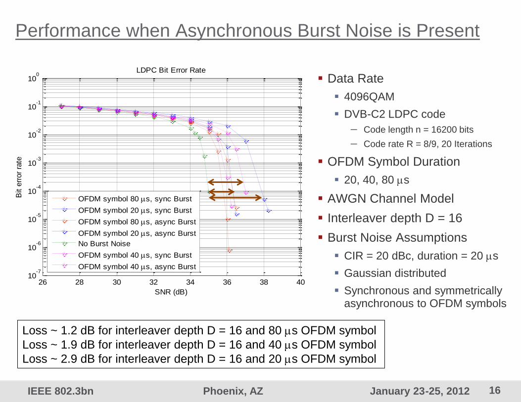
26 28 30 32 34 36 38 4010
-7
10-6
10-5
10-4
10-3
10-2
10-1
100
Bit e
rror
rate
SNR (dB)
LDPC Bit Error Rate
OFDM symbol 80 s, sync Burst
OFDM symbol 20 s, sync Burst
OFDM symbol 80 s, async Burst
OFDM symbol 20 s, async Burst
No Burst Noise
OFDM symbol 40 s, sync Burst
OFDM symbol 40 s, async Burst
Performance when Asynchronous Burst Noise is Present
Data Rate
4096QAM
DVB-C2 LDPC code
– Code length n = 16200 bits
– Code rate R = 8/9, 20 Iterations
OFDM Symbol Duration
20, 40, 80 s
AWGN Channel Model
Interleaver depth D = 16
Burst Noise Assumptions
CIR = 20 dBc, duration = 20 s
Gaussian distributed
Synchronous and symmetrically asynchronous to OFDM symbols
Loss ~ 1.2 dB for interleaver depth D = 16 and 80 s OFDM symbol
Loss ~ 1.9 dB for interleaver depth D = 16 and 40 s OFDM symbol
Loss ~ 2.9 dB for interleaver depth D = 16 and 20 s OFDM symbol
17 IEEE 802.3bn Phoenix, AZ January 23-25, 2012
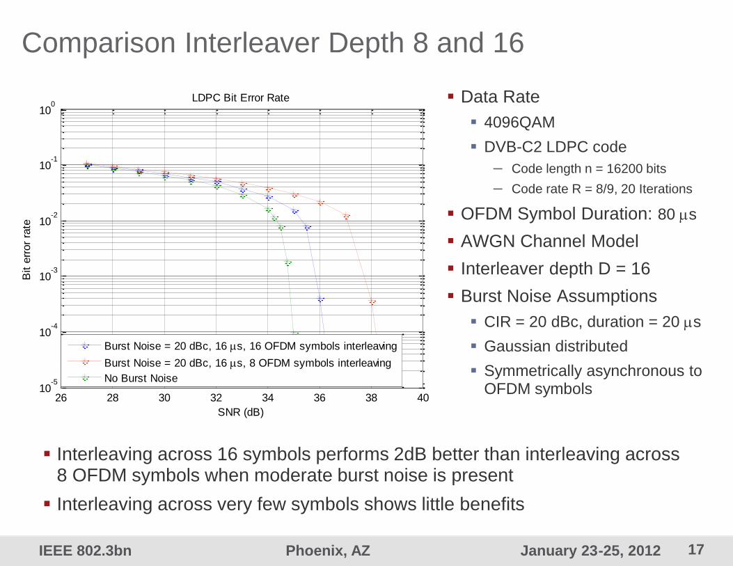
Comparison Interleaver Depth 8 and 16
26 28 30 32 34 36 38 4010
-5
10-4
10-3
10-2
10-1
100
Bit e
rror
rate
SNR (dB)
LDPC Bit Error Rate
Burst Noise = 20 dBc, 16 s, 16 OFDM symbols interleaving
Burst Noise = 20 dBc, 16 s, 8 OFDM symbols interleaving
No Burst Noise
Data Rate
4096QAM
DVB-C2 LDPC code
– Code length n = 16200 bits
– Code rate R = 8/9, 20 Iterations
OFDM Symbol Duration: 80 s
AWGN Channel Model
Interleaver depth D = 16
Burst Noise Assumptions
CIR = 20 dBc, duration = 20 s
Gaussian distributed
Symmetrically asynchronous to OFDM symbols
Interleaving across 16 symbols performs 2dB better than interleaving across 8 OFDM symbols when moderate burst noise is present
Interleaving across very few symbols shows little benefits

18 IEEE 802.3bn Phoenix, AZ January 23-25, 2012
Conclusions
A frame structure was proposed with 1-2% pilot overhead
Pilot density supports channels with up to 4 s delay spread
Pilot pattern allows for estimation of phase noise and I/Q imbalance
The impact of CP length has been analyzed for ReDeSign channels
ReDeSign like channels require CP durations of almost 4 s and longer OFDM symbol for optimum performance
The DVB-C2 codes should be used in downstream direction
Main advantage is that they are fully specified and field-proven
The need for time interleaving depends on the burst model and details are for further study
Required interleaver depth depends on the burst noise model and the OFDM symbol duration
Longer OFDM symbols provide better protection against burst noise than shorter OFDM symbols

19 IEEE 802.3bn Phoenix, AZ January 23-25, 2012
thank you


![Low Complexity Synchronization Design of an OFDM … · · 2015-05-20The OFDM symbol synchronization [3] usually ... With the improvement of the digital signals processing, the](https://static.documents.pub/doc/80x56/5ae5e2607f8b9aee078c267e/low-complexity-synchronization-design-of-an-ofdm-ofdm-symbol-synchronization.jpg)


