This book covers all the topics in a clear and organized format for the Second year Diploma in Printing Technology students as prescribed by the Directorate of Technical Education, Chennai, Tamilnadu. It is confidently believed that this book furnishes the students the necessary study material. The topics covered were neatly illustrated for better understanding of the students.
The book’s step-by-step lessons in large, eye pleasing calligraphy make it suitable for both direct one-to-one tutoring and regular classroom use. The book is prepared in normal everyday English and is free from professional jargon characteristic of so many reading instruction books.
All of the lesson pages were carefully designed to eliminate distraction and to focus the pupil’s full attention on the work at hand.
S.Aunjunaivalavan, Lecturer/ Print. Tech.
S.Uthanu Mallayan, Lecturer/ Print. Tech.
Arasan Ganesan Polytechnic College
Sivakasi.
CONTENTS
SI.No List of Excises Page No.
1. Feeder setting in single color sheet-fed offset printing machines 1
2. Delivery setting in single color sheet-fed offset printing machines 8
3. Setting sheet registering devices 10
4. Roller setting in dampening system 13
5. Roller setting in inking system 19
6. Preparation of fountain solution and dampening system 25
7. Preparation of inking system 28
8. Make ready procedures for single color printing 30
9. Two color printing in single color sheet-fed offset printing machine 33
10. Cleaning of dampening and inking systems 37
AGPC, SIVAKASI OFFSET MACHINES PRACTICAL
1
Ex no: 1: FEEDER SETTING IN SINGLE COLOR SHEETFED OFFSET MACHINE
Aim:
To know the feeder setting in single color sheet fed offset printing machines.
Feeder Board:
This is the main device present over the pile board, the main function of the feeder head is to separate the sheet and pass them one by one to the print unit. In the feeder head suckers, blowers, sheet separations strips, brushes etc., are present and are adjusted for the correct passing of paper for printing.
Pile height governor governs the height of the pile during sheet suction while feeding. The devices have a sensor which senses the pile height. This is because needed for each and every sheet feeding from the pile board gap between the pile board and feeder head gets increased. The suckers sucks the sheet by air suction and when the gap gets increased then suckers do not sucks the sheets, so suckers must be kept in the correct distance inorder to suck the sheet.
Pile Setting:
The pile in the pile board is centered in the board by folding the sheets in half and pile is positioned in the pile board by using scale in the facing plate of the feeder. After centering, side allowance of about 5mm should be allowed for the sheet into the center of the pile board opposite to the pulling of sidelay.
In the feeder head the suckers, blowers, strips, brushes, governor etc., are set over the pile of sheet in such a way that they helps the suckers for the single sheet separation while feeding.
Feeder Board Adjustments:
Feed board is an intermediate device present between the pile board and printing unit which help to move the sheets from the pile board one after the other for printing unit.
In the feed board at the starting and finishing ends two rotating shafts are present which moves the endless tapes connected on its surface. Over the endless tapes the metal wheels, rubber wheels, ball smoothers, tape wheels, brush wheels etc., are present and they must be set in correct pressure over the tapes in order to transport the sheets into the printing unit. The endless tapes must also present in correct tension over the shaft for rotating the wheels present over its surface.
Double Sheet Detector:
The double sheet deflection is set by placing the sheets between the detector and a trip switch wheel, the double sheet detectors are set by placing three sheets between the detector wheel and a trip switch present into the feed board. When two sheets passes the detectors by overlapping the back edge, the detectors will allow to pass the sheets because of the gap set to three sheets. If more than two sheets pass the detector will trip the machine.
AGPC, SIVAKASI OFFSET MACHINES PRACTICAL
2
Front Lay Adjustments:
This is a device present in the last edge of the feeder board. In the machine the front lay which is pivoted below from the feeder board is present. The front lay pieces are adjusted to the size of the sheet to be printed. Mainly two or four pieces are required to position the of sheet registration.
Side Lay Adjustments:
It is a device which is used for the side registration of image in the substrate. In the sidelay a movable bar and a rotating wheel is present. The sidelay can be moved sideways in the bar and fixed in correct position for the required placement of image over the substrate. Due to the movement of the bar, the paper gets pulled and registered in the lay piece of sidelay.
Types of Feeder:
The feeder is divided two types they are,
Single sheet feeder
Stream feeder
Single sheet Feeder:
These are the feeder which feeds the paper single by single one after the other for printing. This feeder works by front separation principles. In this feeder the feeder head is present at the front edge of pile board. These feeders are present in mini offset machines.
Stream Feeder:
These are the feeders which feeds the sheets continuous to one over other in overlapping. These feeders works by back separation principle. In this feeder the feeder head is present at the back edge of the pile board. These feeders are fast when compared to the front separation feeders. Theses feeders are present in high speed machines and offset machines.
AGPC, SIVAKASI OFFSET MACHINES PRACTICAL
3
AGPC, SIVAKASI OFFSET MACHINES PRACTICAL
4
Conclusion:
Thus we have known the adjustments of automatic feeders in single color sheet fed
offset machine.
AGPC, SIVAKASI OFFSET MACHINES PRACTICAL
5
Ex. No. 1: Viva Questions
1. What are the classifications of automatic feeders?
Friction Feeding, Pneumatic Feeding
2. What are the types of pneumatic feeders?
Single sheet Feeding, Stream Feeding.
3. What is the other name for single sheet feeder?
The other name for single sheet feeder is successive feeder.
4. What is the other name for stream feeder?
The other name for stream feeder is Continuous feeder.
5. What are the sheet registering devices?
Side lay and Front Lay
6. What are the two types of front lays?
1. Pivoted above from the feed board
2. Pivoted below from the feed board
7. What are the uses of front lays?
Front lays are used to register the front edge of the unprinted sheets without any
cross.
8. What are the types of side lay?
Push type side lay and pull type side lay.
9. What is a side lay?
Side lay are used for the side registration of paper before printing. These are
present at the side of the feed board area.
10. What is three point register system?
The registration of the paper over the feed board in a way of paper edges contact two point at the front lay and one point at the side lay.
11. What are the delivery assist devices?
Suction slow down and blow down.
12. What are the feeder head components?
The Feeder head components are air blast nozzles rear pickup suckers, forwarding pickup suckers. Sheet steadier, separation brushes and metal fingers.
13. What is air blast nozzle?
This component is present at the feeder head and used to blow forced air at the back edge of the pile board where the paper pile is present. The air lifts the paper at the back edge which helps for the separation of single sheets for printing.
14. What is rear pick up suckers?
AGPC, SIVAKASI OFFSET MACHINES PRACTICAL
6
This is the suckers present in the machine works by back separation principle. This
sucker sucks the air to separate the sheets in the pile board of back edge. The other name
of the rear pickup suckers is lifting suckers.
15. What is the other name of rear pickup suckers?
Lifting suckers.
16. What is forwarding pickup suckers?
These are the suckers present after the rear pickup suckers which receives the
paper from the lifting suckers and forward the received sheet one after one into the feed
board area.
17. What is the other name of forwarding pickup suckers?
Forwarding Suckers.
18. What is sheet steadier’s?
The sheet steadier are present in the feeder head and it is provided in a manner that
its flat edge contacts in the two side edges and rear edge of the stacked paper to avoid the
displacement of paper during lifting and forwarding operation. These sheets steadier are
having up and down movement.
19. What are separator brushes?
The brushes are used in the feeder head which are used to avoid the passing of
double sheet for printing during sheet separation operation.
20. What is metal finger?
The metal strips are used in the feeder head which are used to avoid the passing
the double sheet for printing during sheet separation.
21. What are the types of suckers?
1. Forwarding suckers
2. Lifting Suckers
3. Lifting and Forwarding suckers.
22. What is the other name for sheet separation brushes?
Combers
23. What is the other name for metal fingers?
Metal Strips
24. What is sheet control?
Controlling the sheet from pile board up to the first printing unit.
25. What is Bosses?
These are the devices present over the feed board for controlling the transportation
Side lay, front lay, metal roller, ball smoothers, moving belts. These are called as
bosses.
28. What is a friction feeder?
The Friction feeders are nothing but a roller mechanism is arranged at the front
edge of the paper stacked in the pile board. Due to the movement of the roller and its
friction the paper gets passed into the printing unit.
29. Which type of feeder works on front separation principle?
Single sheet feeder.
30. Which type of feeders works on back separation principle?
Continuous sheet feeder
31. What is lifting and forwarding suckers?
These suckers are also present at the back edge of the paper at the pile board. These suckers perform both the lifting and forwarding operation on the paper so this sucker is called Lifting and Forwarding Suckers.
AGPC, SIVAKASI OFFSET MACHINES PRACTICAL
8
EX NO: 2 DELIVERY SETTING IN SINGLE COLOR SHEET FED OFFSET MACHINE
AIM:
To learn about the setting of delivery in the single color offset machine.
PROCEDURE:
The delivery setting is more important in order to stack the printed sheets neatly. For setting the guides in the delivery pile board, the paper to be printed is placed over the pile board and according to the size of the paper the side joggers are moved. At the movement they should be set in a way that their towards movements it contacts the edges of the printed paper to stack them properly. The skeleton wheels and star wheels are moved in the shaft according to their surface contacts the non-image area of the printed paper to avoidsmeering or marking problem. The air suction of the suction slowdowns and blowing of blow downs are adjusted according to the thickness of the stock.
Conclusion:
Thus the delivery have been set properly in the single color sheetfed offset machine.
AGPC, SIVAKASI OFFSET MACHINES PRACTICAL
9
Ex. No. 2: Viva Questions
1. What is a delivery board?
The board which stacks the printed paper on its surface.
2. What is a rear jogger?
This is a device present at the back of the delivery board which moves to and fro to
jog the pile of paper delivered.
3. What are side joggers?
These are present at the side of the delivery board which moves and jog neatly the
side edge of printed paper.
4. What is front stopper?
This is the device which is used to stop the printed paper during delivery.
5. What are star wheels?
These are present over metal bar and are rotatable. These are used for the support
of printed paper movement during delivery. These can be moved sideways over the metal
bar.
6. What are skeleton wheels?
These wheels are present over the rotating shaft. These wheels are used as the
support for the printed paper movement during delivery.
7. What is suction slowdowns?
This is the device which is present at the printed paper before delivery which sucks
the air to slow the speed of the printed paper at the delivery.
8. What are blow downs?
These devices are also present nearer to the delivery which blows the air to deliver
the printed sheets on the delivery board.
9. What is set off?
The wet ink from the first delivered sheet forms at the backside of the next printed
sheet delivered.
10. What are the antisetoff devices?
Powder sprayer and Liquid sprayer.
11. Where powder sprayers and liquid sprayers are found?
In single color machine powder sprayers are present and in the multicolor machines
liquid sprayers are present.
AGPC, SIVAKASI OFFSET MACHINES PRACTICAL
10
EX NO: 3 SETTING SHEET REGISTERING DEVICE
AIM:
To set the registering device for the accurate registration of printing images.
PROCEDURE:
The sheet is forwarded into the feeder board to contact and stop at the front lay by switch on the blowers, suckers and by inching the machine. After the sheet gets stopped the sidelay is set about 5mm away from the paper that is registering point contacts while the pulling of the sheets. The front lay is set at two or four points according to the size of the paper to be printed. The side lays used in our machine is pull type sidelay and the front lay used in our machine is pivoted below from the feed board. The side lays and front lays must always be kept clean without any dust or dirt accumulation for correct registration during printing. During setting of the front lays and side lays the metal wheels on the last point of the feeder board must be set by slight contact at the back edge of the sheet to be printed in order to push the sheet into the insertion grippers.
AGPC, SIVAKASI OFFSET MACHINES PRACTICAL
11
Conclusion:
Thus the sheet registering devices are set for correct registration of sheet during printing.
AGPC, SIVAKASI OFFSET MACHINES PRACTICAL
12
Ex. No. 3: Viva Questions
1. What is sheet registration?
The method of aligning the sheets in a square before it extensive to the printing unit is
called sheet registration.
2. What are the sheet registering devices?
1. Front lay
2. Side lay
3. What are the two types of front lays?
1. Pivoted above from the feed board.
2. Pivoted below from the feed board.
4. What are two types of side lays?
Push type side lay and pull type side lay.
5. What is lay piece?
The area where the sheet gets contact in the side lay and front lay while registration is
called lay piece.
6. In which type of offset machine push type sidelay is present?
Mini offset machine.
7. In which type of offset machine the pull type sidelay is present?
Offset machine.
AGPC, SIVAKASI OFFSET MACHINES PRACTICAL
13
Ex no: 4 ROLLER SETTING IN DAMPENING SYSTEM
Aim:
To learn about the roller setting for dampening system.
Dampening System Roller Setting:
Setting of pressure between the dampening rollers is critical. The setting of form rollers with oscillating roller and the plate is very important.
1. If the contact pressure is less the dampening solution will not transfer properly (high amount will transfer) and the form roller will not rotate in full speed with oscillator.
2. If the contact pressure is more than the required amount of the dampening solution will not be transferred, also the more pressure will squeegee dampening solution and increase plate wear.
Roller Setting Procedure:
1. The Roller setting is done with plastic strips of thickness 0.05 mm
2. The Nine film strips are cut with three strips of size 1x12” and six strips of Size 2x12”
3. Three sandwiches are made by placing 1x12” plastic strips in between 2x12” plastic strips.
4. Two sandwiches are inserted about 3 inches from each end and the third one at middle.
5. The Middle strip is pulled and checked for pressure
6. For proper pressure, the roller cloth covers should be clean and soft and also the oscillator should be clean.
AGPC, SIVAKASI OFFSET MACHINES PRACTICAL
14
7. If the pressure pulled is even and in required level in three ends then the roller setting is correct.
8. While pulling the strips if any strip is observed not having proper pressure then the pressure setting is adjusted for that strip present in the particular area and the above procedures are again done up to the proper setting of rollers.
Roller Setting between Plates to the form roller:
1. See the adjustment of forme rollers in the machine.
2. Mount the plate over the plate cylinder with correct packing.
3. The Nine film strips are cut with three strips of size 1x12” and six strips of Size 2x12”
4. Three sandwiches are made by placing 1x12” plastic strips in between 2x12” plastic strips.
5. Two sandwiches are inserted about 3 inches from each end and the third one at middle between plate and forme rollers.
6. Now the machine is inch slowly in order to grip the sandwiches between plate in the plate cylinder and forme rollers.
7. Now the Middle strips in each sandwiches are pulled and checked for pressure.
8. For proper pressure, the roller cloth covers should be clean and soft and also the oscillator should be clean.
9. If the pressure pulled is even and in required level in three ends then the roller setting is correct.
10. We can also use the roller setting gauge for even observation of pressure.
11. While pulling the strips if any strip is observed not having proper pressure then the pressure setting is adjusted for that strip present in the particular area and the above procedures are again done up to the proper setting of rollers.
AGPC, SIVAKASI OFFSET MACHINES PRACTICAL
15
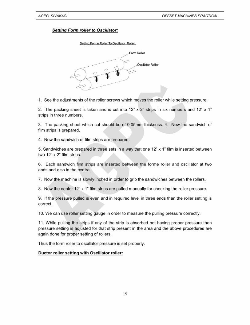
Setting Form roller to Oscillator:
1. See the adjustments of the roller screws which moves the roller while setting pressure.
2. The packing sheet is taken and is cut into 12” x 2” strips in six numbers and 12” x 1” strips in three numbers.
3. The packing sheet which cut should be of 0.05mm thickness. 4. Now the sandwich of film strips is prepared.
4. Now the sandwich of film strips are prepared.
5. Sandwiches are prepared in three sets in a way that one 12” x 1” film is inserted between two 12” x 2” film strips.
6. Each sandwich film strips are inserted between the forme roller and oscillator at two ends and also in the centre.
7. Now the machine is slowly inched in order to grip the sandwiches between the rollers.
8. Now the center 12” x 1” film strips are pulled manually for checking the roller pressure.
9. If the pressure pulled is even and in required level in three ends than the roller setting is correct.
10. We can use roller setting gauge in order to measure the pulling pressure correctly.
11. While pulling the strips if any of the strip is absorbed not having proper pressure then pressure setting is adjusted for that strip present in the area and the above procedures are again done for proper setting of rollers.
Thus the form roller to oscillator pressure is set properly.
Ductor roller setting with Oscillator roller:
AGPC, SIVAKASI OFFSET MACHINES PRACTICAL
16
1. Clean the Dampening rollers without any ink or washing chemicals.
2. Inch the machine manually till the ductor roller contacts the oscillator.
3. The packing sheet is taken and is cut into 12” x 2” strip in six numbers and 12” x 1” strips in three numbers.
4. The packing sheet which cut should be of 0.05mm thickness.
5. Now the sandwich of film strips is prepared.
6. Sandwiches are prepared in three sets in a way that one 12” x 1” film is inserted between two 12” x 2” film strips.
7. Each sandwich film strips are inserted between the doctor roller and oscillator at two ends and also inserted in the centre.
8. Now the machine is slowly inched in order to grip the sandwiches between these two rollers.
9. Now the center 12” x 1” film strips are pulled manually for checking the roller pressure.
10. If the pressure pulled is even and in required level in three ends then the roller setting is correct.
11. We can use roller setting gauge in order to measure the pulling pressure correctly.
12. While pulling the strips if any strip is observed not having proper pressure then pressure setting is adjusted for that strip present in the particular area and the above procedures are again done up to proper setting of rollers.
13. In the same way the ductor roller pressure must be correctly set with duct roller. For that the ductor roller is moved to contact the duct roller and film strips are inserted between these two rollers and pressure is set correctly like ductor roller to oscillator roller.
Thus the pressure between the ductor roller to oscillator is set properly.
Ductor roller setting with Water Pan roller:
AGPC, SIVAKASI OFFSET MACHINES PRACTICAL
17
1. Clean the Dampening rollers without any ink or washing chemicals.
2. Inch the machine manually till the ductor roller contacts the oscillator.
3. The packing sheet is taken and is cut into 12” x 2” strip in six numbers and 12” x 1” strips in three numbers.
4. The packing sheet which cut should be of 0.05mm thickness.
5. Now the sandwich of film strips is prepared.
6. Sandwiches are prepared in three sets in a way that one 12” x 1” film is inserted between two 12” x 2” film strips.
7. Each sandwich film strips are inserted between the ductor roller and water pan roller at two ends and also inserted in the centre.
8. Now the machine is slowly inched in order to grip the sandwiches between these two rollers.
9. Now the center 12” x 1” film strips are pulled manually for checking the roller pressure.
10. If the pressure pulled is even and in required level in three ends then the roller setting is correct.
11. We can use roller setting gauge in order to measure the pulling pressure correctly.
12. While pulling the strips if any strip is observed not having proper pressure then pressure setting is adjusted for that strip present in the particular area and the above procedures are again done up to proper setting of rollers.
13. In the same way the ductor roller pressure must be correctly set with duct roller. For that the ductor roller is moved to contact the duct roller and film strips are inserted between these two rollers and pressure is set correctly like ductor roller to oscillator roller.
Thus the pressure between the ductor roller to Water Pan roller is set properly.
AGPC, SIVAKASI OFFSET MACHINES PRACTICAL
18
Ex. No. 4: Viva Questions
1. What is roller setting?
Setting the contact pressure between the rollers to allow required amount of
dampening solution or ink during printing.
2. By which method the dampening rollers are set?
Film strip method.
3. What is sandwitch?
Composite of three layers of materials.
4. Which is used to measure the pressure during roller setting?
Pressure setting gauge.
5. What are the types of dampening system?
Conventional and continuous dampening system.
6. What is the pH value of dampening solution?
4.5 to 5.5
7. In how many places the sandwiches are placed during roller setting?
Three places.
8. Which is used to prepare the film strips?
Packing sheet is cut and used as the film strips.
AGPC, SIVAKASI OFFSET MACHINES PRACTICAL
19
Ex no: 5 ROLLER SETTING IN INKING SYSTEM
Aim:
To learnt about the roller setting for inking system.
Inking unit Roller Setting:
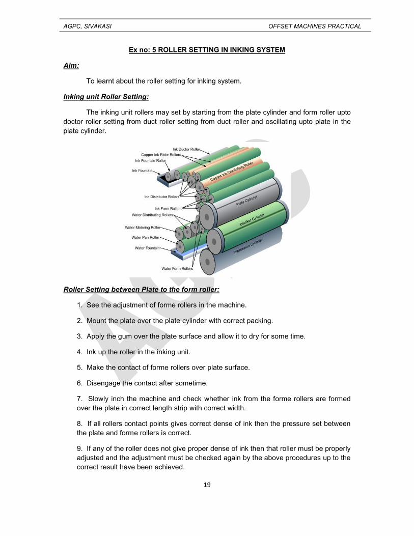
The inking unit rollers may set by starting from the plate cylinder and form roller upto doctor roller setting from duct roller setting from duct roller and oscillating upto plate in the plate cylinder.
Roller Setting between Plate to the form roller:
1. See the adjustment of forme rollers in the machine.
2. Mount the plate over the plate cylinder with correct packing.
3. Apply the gum over the plate surface and allow it to dry for some time.
4. Ink up the roller in the inking unit.
5. Make the contact of forme rollers over plate surface.
6. Disengage the contact after sometime.
7. Slowly inch the machine and check whether ink from the forme rollers are formed over the plate in correct length strip with correct width.
8. If all rollers contact points gives correct dense of ink then the pressure set between the plate and forme rollers is correct.
9. If any of the roller does not give proper dense of ink then that roller must be properly adjusted and the adjustment must be checked again by the above procedures up to the correct result have been achieved.
AGPC, SIVAKASI OFFSET MACHINES PRACTICAL
20
Setting Form roller to Oscillator:
1. See the adjustments of the roller screws which moves the roller while setting pressure.
2. The packing sheet is taken and is cut into 12” x 2” strips in six numbers and 12” x 1” strips in three numbers.
3. The packing sheet which cut should be of 0.05mm thickness.
4. Now the sandwich of film strips is prepared.
5. Sandwiches are prepared in three sets in a way that one 12” x 1” film is inserted between two 12” x 2” film strips.
6. Each sandwich film strips are inserted between the forme roller and oscillator at two ends and also in the centre.
7. Now the machine is slowly inched in order to grip the sandwiches between the rollers.
8. Now the center 12” x 1” film strips are pulled manually for checking the roller pressure.
9. If the pressure pulled is even and in required level in three ends then the roller setting is correct.
AGPC, SIVAKASI OFFSET MACHINES PRACTICAL
21
10. We can use roller setting gauge in order to measure the pulling pressure correctly.
11. While pulling the strips if any of the strip is absorbed not having proper pressure then pressure setting is adjusted for that strip present in the area and the above procedures are again done for proper setting of rollers.
Thus the form roller to oscillator pressure is set properly.
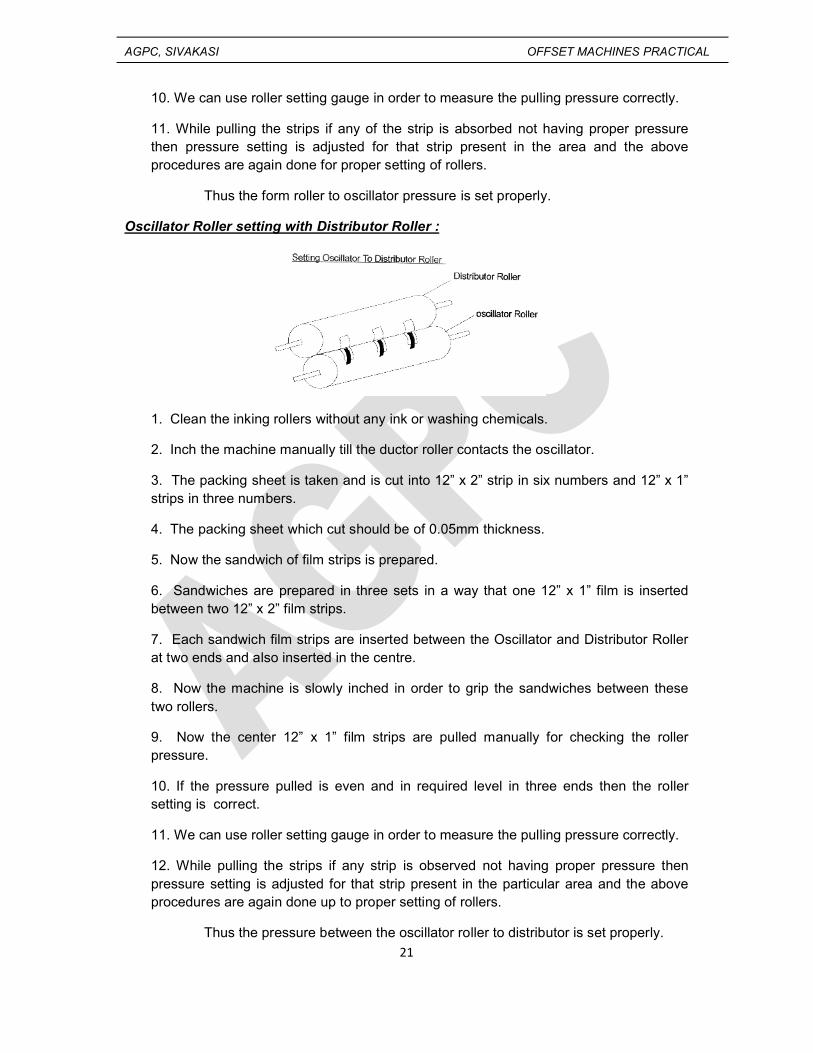
Oscillator Roller setting with Distributor Roller :
1. Clean the inking rollers without any ink or washing chemicals.
2. Inch the machine manually till the ductor roller contacts the oscillator.
3. The packing sheet is taken and is cut into 12” x 2” strip in six numbers and 12” x 1” strips in three numbers.
4. The packing sheet which cut should be of 0.05mm thickness.
5. Now the sandwich of film strips is prepared.
6. Sandwiches are prepared in three sets in a way that one 12” x 1” film is inserted between two 12” x 2” film strips.
7. Each sandwich film strips are inserted between the Oscillator and Distributor Roller at two ends and also inserted in the centre.
8. Now the machine is slowly inched in order to grip the sandwiches between these two rollers.
9. Now the center 12” x 1” film strips are pulled manually for checking the roller pressure.
10. If the pressure pulled is even and in required level in three ends then the roller setting is correct.
11. We can use roller setting gauge in order to measure the pulling pressure correctly.
12. While pulling the strips if any strip is observed not having proper pressure then pressure setting is adjusted for that strip present in the particular area and the above procedures are again done up to proper setting of rollers.
Thus the pressure between the oscillator roller to distributor is set properly.
AGPC, SIVAKASI OFFSET MACHINES PRACTICAL
22
Ductor roller setting with Oscillator roller :
1. Clean the inking rollers without any ink or washing chemicals.
2. Inch the machine manually till the ductor roller contacts the oscillator.
3. The packing sheet is taken and is cut into 12” x 2” strip in six numbers and 12” x 1” strips in three numbers.
4. The packing sheet which cut should be of 0.05mm thickness.
5. Now the sandwich of film strips is prepared.
6. Sandwiches are prepared in three sets in a way that one 12” x 1” film is inserted between two 12” x 2” film strips.
7. Each sandwich film strips are inserted between the ductor roller and oscillator at two ends and also inserted in the centre.
8. Now the machine is slowly inched in order to grip the sandwiches between these two rollers.
9. Now the center 12” x 1” film strips are pulled manually for checking the roller pressure.
10. If the pressure pulled is even and in required level in three ends then the roller setting is correct.
11. We can use roller setting gauge in order to measure the pulling pressure correctly.
12. While pulling the strips if any strip is observed not having proper pressure then pressure setting is adjusted for that strip present in the particular area and the above procedures are again done up to proper setting of rollers.
Thus the pressure between the oscillator to ductor roller is set properly.
Ductor roller setting with Duct roller :
AGPC, SIVAKASI OFFSET MACHINES PRACTICAL
23
1. Clean the inking rollers without any ink or washing chemicals.
2. Inch the machine manually till the ductor roller contacts the oscillator.
3. The packing sheet is taken and is cut into 12” x 2” strip in six numbers and 12” x 1” strips in three numbers.
4. The packing sheet which cut should be of 0.05mm thickness.
5. Now the sandwich of film strips is prepared.
6. Sandwiches are prepared in three sets in a way that one 12” x 1” film is inserted between two 12” x 2” film strips.
7. Each sandwich film strips are inserted between the ductor roller and duct roller at two ends and also inserted in the centre.
8. Now the machine is slowly inched in order to grip the sandwiches between these two rollers.
9. Now the center 12” x 1” film strips are pulled manually for checking the roller pressure.
10. If the pressure pulled is even and in required level in three ends then the roller setting is correct.
11. We can use roller setting gauge in order to measure the pulling pressure correctly.
12. While pulling the strips if any strip is observed not having proper pressure then pressure setting is adjusted for that strip present in the particular area and the above procedures are again done up to proper setting of rollers.
Thus the pressure between the ductor to duct roller is set properly.
Ex. No. 5 : Viva Questions
AGPC, SIVAKASI OFFSET MACHINES PRACTICAL
24
1. What is inking system roller setting?
Setting the correct pressure between the inking rollers in order to supply required
amount of ink during printing.
2. What are the dimensions of film strips used for roller setting?
12”x2” and 12”x 1”
3. How the sandwitch is prepared?
By placing one 12”x1” film strip between 12”x2” film strips.
4. By which method the forme roller to plate cylinder pressure being set?
Ink strip method.
5. Which film strip in the sandwitch is pulled for setting the rollers?
The centre 12”x1” film strips in the sandwitch placed at the three ends is pulled.
Ex no:6 PREPARING OF FOUNTAIN SOLUTION AND DAMPENING SYSTEM
AGPC, SIVAKASI OFFSET MACHINES PRACTICAL
25
Aim:
To learn about the fountain solution ingredients and to mix with water to make it as dampening solution for offset printing.
Fountain Solution:
This solution composed of a lot of ingredients. The fountain solution is mixed with water in offset printing to
1. Apply even dampening solution over the plate.2. To give wettability.3. Avoid surface tension.
The fountain solution is prepared by mixing the following ingredients.
(i) Acid or Base:
The Acid or Base present in the Fountain solution is used to maintain the pH value while the dampening solution is mixed during printing
(ii) Gum:
The gum Arabic solution is used in the fountain solution to desensitize the non-image of the plate.
(iii) Corrosion inhibitors:
These are present in the fountain solution to avoid the reaction of ingredients over the plate to form corrosion.
(iv) Buffer:
AGPC, SIVAKASI OFFSET MACHINES PRACTICAL
26
Magnesium Nitrate is used as the buffer in the fountain solution which neutralizes the acidity or alkalinity of the solution.
(v) Wetting Agent:
ISO Propyl alcohol is used as the wetting agent. It reduces the surface tension of water in the dampening solution.
(vi) Drying Stimulator:
During the contact of ink and water over the plate surface the drying capability of the ink becomes low. Hence the drying stimulator helps to speed up the drying of ink.
(vii)Fungicide:
This is used to avoid the formation of fungus while using the dampening solution in the duct.
(viii) Anti foaming Agent:
This is added in the fountain solution to avoid the formation of foams (bubbles) in the dampening solution, when the dampening solution is used in the fountain duct.
(ix) Alcohol:
ISO Propyl Alcohol is used in the fountain solution. This is used to increase the contact angle and reduce the surface tension of water during the use of dampening solution.
Preparing the Dampening:
Dampening system is used to supply the required amount of dampening solution of the plate surface. In our machine five rollers are present in the dampening solution the rollers should store an amount of dampening solution on its surface. For the reason three or five roller surfaces are covered with an absorbent cloth called molten cloth.
For preparing the dampening system, check the body surface of the dampening roller and their covers. The dampening roller and their covers are dampened before the rollers are fixed in the dampening units because some more time is required for even absorbency of water supply on their surface.
After wetting the surface of the roller covers, the dampening rollers are fixed in the required area fountain solution and water mixture is used as the dampening solution.
Conclusion:
Thus we have prepared the fountain solution and the dampening system for printing.
AGPC, SIVAKASI OFFSET MACHINES PRACTICAL
27
Ex. No. 6 : Viva Questions
1. What is dampening solution?
The mixture of fountain solution and water is called dampening solution.
2. What is the name of the cloth cover used to cover the dampening rubber rollers?
Molletton cloth.
3. What is the use of dampening cloth cover?
To store and supply the dampening solution.
AGPC, SIVAKASI OFFSET MACHINES PRACTICAL
28
EX NO:7 PREPARATION OF INKING SYSTEM
AIM:
To prepare the inking system for printing.
PROCEDURE:
The inking system must be prepared in a correct manner in order to supply required amount of ink to the plate during printing. First all the ink keys which moves the metal blade to the duct roller are tightened. Then the ink is poured into the duct. Then after according to the presence of image values the ink keys are loosened for required amount of ink supply to the plate. Now the machine is run and the nob which makes the contact of the doctor roller and oscillator is also to be on. The nob which is used to rotate the duct roller inside the duct has to be placed in the required position, according to the position the ink supply will be more or less. After all these operations are correctly performed, we may able to see the transfer of ink in the inking rollers and when the impression gets on, the ink from the inking system is transferred to the plate surface.
Conclusion:
Thus the inking system is prepared for printing a job.
AGPC, SIVAKASI OFFSET MACHINES PRACTICAL
29
Ex. No. 7 : Viva Questions
1. What is the purpose of inking system?
To supply the required amount of ink for printing.
2. What is an inking system consists of?
Ink duct, flexible metal blade, duct roller, and roller train.
3. What is roller train?
Number of rubber and metal rollers arranged alternatively up to the plate cylinder.
4. What is the purpose of set and draw screws?
To increase or decrease the supply of ink from the ink duct in the required areas.
5. In which metals the metal rollers are made of?
Copper, ebonite and rilson.
6. What is the use of oscillator?
It oscillates sideways for fine grinding of ink.
7. What is the use of forme rollers?
To apply the ink on the image areas of the plate.
8. What is the use of rider roller?
To remove the foreign particles accumulated in the inking system.
9. What is the other name of rider roller?
Scavenger roller.
10. What type of inking system is used in offset machine?
Multiroller inking system.
AGPC, SIVAKASI OFFSET MACHINES PRACTICAL
30
Ex no:8 MAKEREADY PROCEDURE FOR SINGLE COLOR PRINTING
Aim:
To learn about the make-ready procedure for printing a job.
Prepare the press for new press run:
The setting of a previous job should be reset for printing a new job. The inking system should be washed. The dampening rollers may be cleaned if needed. The plate should be removed and taken for storage.
Checking Copy, Plate, Ink and Paper against Instructions:
The original given for printing is taken and it is observed. Then the image in the plate have to be checked for perfection. The quantity of the paper and the quality of paper also checked for fine printing to give quality results.
Setting the Sheet Handling Mechanism:
Sheet handling mechanisms starts from pile board to front lay. In the pile board the side guides, front stoppers and feeder head are set according to the sheet size. The double sheet detector must be set according to the stock thickness. The feeder board elements and side lays are set according to the size of the stock. These sheet handling mechanisms must be set properly in order to transport the sheets into the printing unit without any stops. The delivery joggers also set according to the paper size for neat stacking of printed papers.
Packing and Mounting the Plate:
The plate used for printing job should be taken and its thickness must be measured. According to the plate thickness the required thickness of packing sheet is taken and is placed between the plate cylinder and the plate during the mounting of the plate. The thickness of the plate and packing is considered according to the undercut of the plate cylinder.
Checking and Preparing the New Blanket (if Possible):
During make-ready of the machine the condition of the blanket must be checked. If the blanket surface is not in good condition or any unrectified low spots are to be found then the blanket is removed from the cylinder and new blanket is mounted with correct packing.
Preparing the Dampening System:
The dampening roller cloth covers are washed to remove the ink particleaccumulation. If any cloth covers got damaged then they should be replaced by a new. Then after these rollers are mounted in the dampening unit. After that the dampening solution is prepared with correct pH level and the prepared solution is poured in the dampening duct.
AGPC, SIVAKASI OFFSET MACHINES PRACTICAL
31
Preparing the inking system:
The inking system rollers must be washed to remove the previous job printed ink. Then the ink to be printed into the ink duct. Then the ink keys are adjusted for supplying the ink from the ink duct roller according to the image present in the plate.
Preparing the Make-ready Books:
During make-ready of job a number of sheets are required to be printed. If we use unprinted sheets then a number of sheets may be wasted during make-ready. To avoid the wastage of white sheets the make-ready books are prepared. The make-ready books are prepared by placing 5 waste sheets to 1 unprinted sheet (5:1 ratio). This books avoids unprinted sheet wastage.
Making Trial Impression:
After the make-ready book was prepared a trial impression was made in the unprinted paper by passing the make-ready book into the printing unit.
Examining the Trial Impression:
From the delivery board the printed white sheet is taken and it is examined through for the registration of image, color density etc., if there is any misregistration (or) in correct color value is found then required adjustments are made and the machine is run to get next trial impression.
Getting OK Order for Printing:
After all the adjustments are made and perfect result is obtained in the paper during the trial impression then the printed paper is taken to the supervisor or other higher authorities to get approval for printing.
Running the Machine:
After getting approval from the authorities the machine is run continuously to print the required number of copies.
Conclusion:
Thus we learnt the make-ready procedures for printing a job.
AGPC, SIVAKASI OFFSET MACHINES PRACTICAL
32
Ex. No. 8 : Viva Questions
1. What is make-ready?
The preparation of all the operations for running a machine is called make-ready.
2. What is premakeready?
Making ready of the preliminary works for the next job and when the machine is
running a present job.
3. What is sheet handling?
The mechanisms which handles the sheets from feeding unit into the printing unit is
This is the book prepared by the combination of waste sheets and unprinted white
sheets.
7. What is the ratio by which make-ready book is prepared?
5 (waste sheets):1(unprinted sheets)
8. What is trial impression?
The impression made in the make-ready book in order to see the position of images
before printing.
AGPC, SIVAKASI OFFSET MACHINES PRACTICAL
33
Ex no:9 TWO COLOR PRINTING IN SINGLE COLOR SHEETFED OFFSET PRINTING MACHINE
Aim:
To learn about two color printing in single sheetfed offset printing machine.
Prepare the press for new press run:
The setting of a previous job should be reset for printing a new job. The inking system should be washed. The dampening rollers may be cleaned if needed. The plate should be removed and taken for storage.
Checking Copy, Plate, Ink and Paper against Instructions:
The original given for printing is taken and it is observed. Then the image in the plate have to be checked for perfection. The quantity of the paper and the quality of paper also checked for fine printing to give quality results.
Setting the Sheet Handling Mechanism:
Sheet handling mechanisms starts from pile board to front lay. In the pile board the side guides, front stoppers and feeder head are set according to the sheet size. The double sheet detector must be set according to the stock thickness. The feeder board elements and side lays are set according to the size of the stock. These sheet handling mechanisms must be set properly in order to transport the sheets into the printing unit without any stops. The delivery joggers also set according to the paper size for neat stacking of printed papers.
Packing and Mounting the Plate:
The plate used for printing job should be taken and its thickness must be measured. According to the plate thickness the required thickness of packing sheet is taken and is placed between the plate cylinder and the plate during the mounting of the plate. The
AGPC, SIVAKASI OFFSET MACHINES PRACTICAL
34
thickness of the plate and packing is considered according to the undercut of the plate cylinder.
Checking and Preparing the New Blanket (if Possible):
During make-ready of the machine the condition of the blanket must be checked. If the blanket surface is not in good condition or any unrectified low spots are to be found then the blanket is removed from the cylinder and new blanket is mounted with correct packing.
Preparing the Dampening System:
The dampening roller cloth covers are washed to remove the ink particle accumulation. If any cloth covers got damaged then they should be replaced by a new. Then after these rollers are mounted in the dampening unit. After that the dampening solution is prepared with correct pH level and the prepared solution is poured in the dampening duct.
Preparing the inking system:
The inking system rollers must be washed to remove the previous job printed ink. Then the ink to be printed into the ink duct. Then the ink keys are adjusted for supplying the ink from the ink duct roller according to the image present in the plate.
Preparing the Make-ready Books:
During make-ready of job a number of sheets are required to be printed. If we use unprinted sheets then a number of sheets may be wasted during make-ready. To avoid the wastage of white sheets the make-ready books are prepared. The make-ready books are prepared by placing 5 waste sheets to 1 unprinted sheet (5:1 ratio). This books avoids unprinted sheet wastage.
Making Trial Impression:
After the make-ready book was prepared a trial impression was made in the unprinted paper by passing the make-ready book into the printing unit.
Examining the Trial Impression:
From the delivery board the printed white sheet is taken and it is examined through for the registration of image, color density etc., if there is any misregistration (or) in correct color value is found then required adjustments are made and the machine is run to get next trial impression.
Getting OK Order for Printing:
After all the adjustments are made and perfect result is obtained in the paper during the trial impression then the printed paper is taken to the supervisor or other higher authorities to get approval for printing.
Running the Machine:
After getting approval from the authorities the machine is run for first color to print the required number of copies.
AGPC, SIVAKASI OFFSET MACHINES PRACTICAL
35
Preparing the Plate For Storage:
After printing the first color the plate should be cleaned with kerosene to remove the ink over the image and it is taken for storage if it is needed for further job.
Inking Roller Washup and Preparing the Inking System:
After the first color was printed the ink present is properly cleaned without any ink particles in the inking roller surface. Then the second color to be printed is filled in the ink duct.
Dampening System Preparation:
After printing the dampening roller must be removed from the dampening system and they must be cleaned in order to remove the accumulation of ink over surface. Then they are fixed in the required places of the dampening unit.
Mounting Second Color Plate:
Now the second color plate is mounted over the cylinder with correct packing.
Making Trial Impression:
After inking unit is cleaned and plate mounted, we have to run the machine for second color printing.
Examine the Trial Impression:
The printed sheet is examined for ink density and correct register of image.
Getting OK Order for Printing:
After all the adjustments are made and perfect result is obtained in the paper during the trial impression then the printed paper is taken to the supervisor or other higher authorities to get approval for printing.
Running the Machine:
After getting approval from the authorities the machine is run for second color to print the required number of copies.
Conclusion:
Thus we learnt the two color printing in single color sheetfed offset printing machine.
Ex. No. 9 : Viva Questions
AGPC, SIVAKASI OFFSET MACHINES PRACTICAL
36
1. What is two color printing?
Printing the two colors one over the other in the sheet is called two color printing.
2. What is trapping?
The acceptance of second printed ink over the first printed ink.
3. What are the two types of trapping?
Wet on wet trapping and wet on dry trapping.
4. What is wet on wet trapping?
The acceptance of second color over the first printed wet ink.
5. What is wet on dry trapping?
The acceptance of second color over the first printed wet ink.
6. Where wet on wet trapping happen?
In multicolor machines.
7. Where wet on dry trapping happen?
Single color machines when used for printing multicolor.
8. What is the four color sequence in single color machine?
Cyan, yellow, magenta and black.
9. What is the four color sequence in two color machine?
Black, cyan, yellow and magenta.
10. What is the four color sequence in two color machine?
Black, magenta, cyan and yellow.
EX NO:10 CLEANING OF INKING AND DAMPENING SYSTEM
AGPC, SIVAKASI OFFSET MACHINES PRACTICAL
37
AIM:
To clean the inking and dampening system after completing a job.
PROCEDURE:
a) INKING SYSTEM CLEANING:
The ink remaining in the duct is taken carefully from the ink duct. Then the metal blade and duct rollers are cleaned by using kerosene using a wash cloth. During this time the doctor roller must be fully out of contact from the duct roller. It should be made contact with the oscillator. Then the ink wash up device is taken and it is inserted in the provisions present near to the distributor roller. Then the washup device is tightened. Now the machine is started for running. During running the machine and when the rollers are rotating, the kerosene is poured over the roller surface. Due to the contact of all inking rollers with one another the solvent or kerosene is transferred to all roller surface and the ink gets cleaned and the ink and solvent particles are finally collected in the wash up device. After cleaning the rollers the washup device is also cleaned to make it free from the waste collected material.
b) DAMPENING SYSTEM CLEANING:
After completing a job, the doctor roller and the forme rollers are removed from the dampening system. They are soaked well with detergents, kerosene and water and the cloth cover surface is scrubbed well in order to remove the ink particles accumulation over the surface. After scrubbing the cloth cover is cleaned well with water. Then the surface is wiped in order to remove if any ink particles are present over the surface. Finally the dampening solution present in the duct is removed and the duct is also cleaned well.
Conclusion:
Thus the inking and dampening systems are cleaned after completing a job.
AGPC, SIVAKASI OFFSET MACHINES PRACTICAL
38
Ex. No. 10 : Viva Questions
1. Why dampening system cleaning is necessary?
To remove the accumulation of ink particles on the cloth cover surface.
2. What is the name of cloth used for covering the dampening rollers?
Molletton cloth.
3. What are the materials used for cleaning the dampening roller covers?
Detergents, kerosene (or ) other washing solvents.
4. Which rollers of the dampening systems are covered by molletton cloth?
Doctor roller and forme roller.
5. What is the purpose of molletton cloth cover?
To store the dampening solution and to supply the required amount during printing.
6. What are the elements present in the ink duct?
Duct, metal roller and a flexible metal blade.
7. What are the parts of the ink wash up device?
Storage duct, blade and screws for tightening or loosening the blade.
8. What are the material used for cleaning the inking system rollers?
Kerosene or washup solution.
9. In which roller the wash up device contacts while inking system washup?
Oscillator roller.
10. What type of dampening system is used in our offset machine?
Conventional dampening system.
11. What type of inking system is used in our machine?