OLD HARBOUR HILL - Preliminary quarry plan 1.11.2010 OLD HARBOUR HILL Preliminary quarry plan Technical Report (Phase 1) September 2010 Jim Stefek Michal Stibitz Project Manager Director, EXAGEN Ltd. Project Team: Bohumil Broz Martin Jacek Oto Vrana Client: CEMCORP CEMENT 15D-61 Yorkville Ave. Toronto, Ontario, Canada M5R 1B7
Transcript
OLD HARBOUR HILL - Preliminary quarry plan 1.11.2010
OLD HARBOUR HILL Preliminary quarry plan
Technical Report (Phase 1)
September 2010
Jim Stefek Michal Stibitz Project Manager Director, EXAGEN Ltd.
OLD HARBOUR HILL - Preliminary quarry plan 1.11.2010
2
TABLE OF CONTENT:
1. INTRODUCTION AND INITIAL INFORMATION ...................................................................................... 5
1.1 TOPOGRAPHIC DOCUMENTS AND OTHER MATERIALS ....................................................................................... 5 1.2 GEOLOGICAL STRUCTURE ................................................................................................................................. 6 1.3 DATA REQUIREMENTS FOR THE FINAL QUARRY PLAN ..................................................................................... 7
5. CONCEPTUAL MINING PLAN ..................................................................................................................... 12
5.1 ACCESSIBILITY ................................................................................................................................................ 12 5.2 MINING PROCESS DESCRIPTION ....................................................................................................................... 13 5.3 OVERBURDEN STRIPPING AND PILE AND RE-UTILIZING .................................................................................. 14 5.4 BLASTING AND RIPPING .................................................................................................................................. 14 5.5 BENCH DESIGN AND CONSTRUCTION .............................................................................................................. 15 5.6 HAUL ROAD AND HAULAGE ............................................................................................................................ 15 5.7 PROCESSING SPECIFICATION AND LOCATION .................................................................................................. 15 5.8 PROPOSED LOCATION OF PROCESSING EQUIPMENT AND RAW MATERIAL STOCKPILES (CRUSHING AREA AND STOCKPILE) ........................................................................................................................................................... 16 5.9 CRUSHING WITH CLAY AND PRODUCT DELIVERY BY BELT CONVEYOR .......................................................... 16 5.10 CLAY SHIPPING IN AND STORAGE AREA ........................................................................................................ 16 5.11 MINING FACILITY EQUIPMENT AND LOCATION ............................................................................................. 16 5.12 PRODUCTION AND DEVELOPMENT SCHEDULE .............................................................................................. 18
5.12.1 Production schedule ............................................................................................................................. 18 5.12.2 Development schedule .......................................................................................................................... 18 5.12.3 Alternatives of quarry opening scenarios ............................................................................................ 19
5.12.3.1 Quarry Opening Scenario 1 ............................................................................................................................. 19 5.12.3.2 Quarry Opening Scenario 2 – Main Scenario ................................................................................................. 20 5.12.3.3 Quarry Opening Scenario 3 ............................................................................................................................. 20 5.12.3.4 Quarry Opening Scenario 4 ............................................................................................................................. 20 5.12.3.5 Quarry development after the initial stage ...................................................................................................... 21
5.13 MINING EQUIPMENT LIST AND SPECIFICATION ............................................................................................. 22 5.14 ROCK HANDLING ........................................................................................................................................... 22 5.15 GRADE CONTROL .......................................................................................................................................... 23
5.16 MINING SUPPORT SERVICES .......................................................................................................................... 24 5.16.1 Mining dedust ....................................................................................................................................... 24 5.16.2 Compressed air distribution ................................................................................................................. 24
6. RECLAMATION AND CLOSURE PLAN ..................................................................................................... 24
6.1 MAGAZINE FOR EXPLOSIVES ........................................................................................................................... 25 6.2 STRUCTURE TO BE DISMANTLED AND LEVELLED ............................................................................................ 25
OLD HARBOUR HILL - Preliminary quarry plan 1.11.2010
3
6.3 STRUCTURE TO BE RETAINED .......................................................................................................................... 25 6.4 MAXIMUM 3:1 SLOPE ...................................................................................................................................... 25 6.5 SINK HOLE, STREAMS AND DRAINS ................................................................................................................. 25
7. CONCLUSION AND RECOMMENDATIONS ............................................................................................. 26
OLD HARBOUR HILL - Preliminary quarry plan 1.11.2010
4
List of figures:
1. Location map 2. Area information map 3. Southeastern view of the deposit area 4. Bench blasting diagram 5. Information map – Options of possible quarry development (Options 1, 2, 3, 4) 6. View of the quarry area after second 10-year production period
List of tables:
1. Table of potential limestone reserves 2. Estimate of volume and tonnage of mineable limestone reserves of individual
production phases 3. Calculation of limestone volume and weight of individual phases of planned quarrying 4. Duration of individual phases of the quarrying operations 5. Estimate of limestone raw material volume in 10-year production periods and phases
of planned production List of Appendices:
1. Orthophoto map of the current state of the area, 1:5,000 scale 2.1 Map of initial phases of planned production (Option 1, Phases 1, 2, 3, 4A, 4B)
with proposed crushing areas and quarry roads, 1:5,000 scale 2.2 Map of initial phases of planned production (Option 2, Phases 1, 2, 3, 4A, 4B)
with proposed crushing areas and quarry roads, 1:5,000 scale 3.1 Map of initial phases of planned production – first 10-year period (Option 1,
Phases 1, 2, 3, 4A, 4B), 1:2,000 scale 3.2 Map of initial phases of planned production – first 10-year period (Option 2,
Phases 1, 2, 3, 4A, 4B), 1:2,000 scale 4. Map of second 10-year period (years 10-20) of planned production (Option 1,
2 Phases 4A, 4B, 6, 7, 8, 9, 10), 1:2,000 scale 5. Map of third 10-year period (years 20-30) of planned production (Option 1, 2
Phases 10, 11), 1:2,000 scale 6. Map of fourth 10-year period (years 30-40) of planned production (Option 1, 2
Phases 11, 12, 13), 1:5,000 scale 7. Map of fifth 10-year period (years 40-50) of planned production (Alternative 1,
2 Phase 13), 1:5,000 scale 8. Map of area after termination of quarrying – reclamation plan, 1:5,000 scale 9. Quarry cross-sections 10. 3D visualization of quarry models (Option 2)
OLD HARBOUR HILL - Preliminary quarry plan 1.11.2010
5
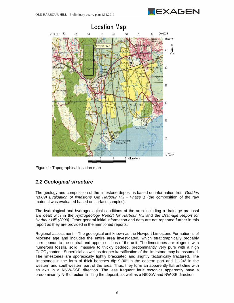
1. Introduction and initial information The proposed limestone quarry development, actual quarrying and cement production is based on a delineated area and other specific requirements. The project area straddles the eastern border of the parishes of Clarendon with that of St. Catherine approximately 4.1 km west of the town of Old Harbour (GR 237 921.72E; 142 941.73N). It is centered at the false grid reference (GR) of 234 000E; 142 000N on the 1:50,000 metric topographic Sheet 17 (JD69 Series) (Fig 1). All grid references used for the remainder of this report are following those on Map 1 which is adapted from the 1:50,000 Sheet 17 topographic JD69 series published by the Jamaican Survey Department. The project area is rectangular approximately 2.88 km2 in area. The project area can be defined by the following grid references based on the 1:50,000 topographic map Sheet 17 Northwestern corner – 233 616E 143 394N Northeastern corner – 234 423E 143 394N Southeastern corner – 234 423E 141 514N Southwestern corner – 233 616E 141 514N Major gullies in the area all flow southwards and includes the Clarendon Gully in the north and then east of the Old Harbour Hill range, the Marmee Gully on the western fringes of the hill and the Palmetto Gully on the low rolling hills southwest of the area. Vegetation coverage of the limestone hills is typically thick shrubs and tree forests. The forest tends to be in the higher elevations and consists of trees such as cedar. Several local fruit trees are also noted scattered through the area, including ackee (Blighia sapida), lime, sweetsop (Annona squamosa) and guinep. Shrubs include thatch (Coccothrinax argentata) and broom weed (Amphiachyris).
1.1 Topographic documents and other materials The topographic documents used for the planning included 1:12,500 scale maps, which were digitized and converted to the metric system and which served as the basis for the construction of a 3D model of the deposit area and for the compilation of 1:5,000 and 1:2,000 scale maps that were used for the quarry proposal. The GRID SURVEY of LANDS known as ROSE HALL plan provided at a scale of 1:8,000 is purely informative, and the grid square system was used only for location descriptions. The maps depict the delineated area known as Rose Hall with the elevation of Old Harbour Hill. Information sources used: • Geddes A.J.S. (2009): EVALUATION OF A LIMESTONE RESOURCE- OLD HARBOUR
HILL, ST. CATHERINE- JAMAICA Phase 1 Report • 2009: DRAINAGE REPORT FOR OLD HARBOUR HILL QUARRY CLARENDON • 2009: HYDRO REPORT FOR OLD HARBOUR HILL, ST. CATHERINE - JAMAICA
OLD HARBOUR HILL - Preliminary quarry plan 1.11.2010
6
Figure 1: Topographical location map
1.2 Geological structure The geology and composition of the limestone deposit is based on information from Geddes (2009) Evaluation of limestone Old Harbour Hill - Phase 1 (the composition of the raw material was evaluated based on surface samples). The hydrological and hydrogeological conditions of the area including a drainage proposal are dealt with in the Hydrogeology Report for Harbour Hill and the Drainage Report for Harbour Hill (2009). Other general initial information and data are not repeated further in this report as they are provided in the mentioned reports. Regional assessment – The geological unit known as the Newport Limestone Formation is of Miocene age and includes the entire area investigated, which stratigraphically probably corresponds to the central and upper sections of the unit. The limestones are biogenic with numerous fossils, solid, massive to thickly bedded, predominantly very pure with a high CaCO3 content. Superficial as well as deeper karstification of the limestone may be assumed. The limestones are sporadically lightly brecciated and slightly tectonically fractured. The limestones in the form of thick benches dip 9-30° in the eastern part and 11-24° in the western and southwestern part of the area. Thus, they form an apparently flat anticline with an axis in a NNW-SSE direction. The less frequent fault tectonics apparently have a predominantly N-S direction limiting the deposit, as well as a NE-SW and NW-SE direction.
OLD HARBOUR HILL - Preliminary quarry plan 1.11.2010
7
The results of the chemical analysis prove that the limestones from surface outcrops have a high CaCO3 content. A heightened to high MgO content was detected in only isolated samples. The contents of other contaminants are very low and favourable to cement grade limestone. The evaluation from the report by Goddes states: “Calcium Carbonate content ranging from 84.47 t0 98.78 %; Magnesium Carbonate content from 0.22 to 13.64 and Silica content from less than 0.2 to 5.78%. High silica and high magnesium carbonate values are found in only a few samples, are highly restricted in space and thus should have no effect on the quarrying activity to provide OPC raw material. More detailed data regarding the quality of the raw material are not available, and the proposed limestone quarry design at this time is based on the assumption of a homogeneous composition with very limited amounts of overburden and unsuitable layers, possibly karst hollows. The stockpiling of the principal limestone constituent for cement raw material mixtures, and of other corrective additives are not dealt with because the vertical profile of their basic chemical composition as well as that of the limestones and clays is not known. Another examination will be conducted as part of a borehole investigation and other surveys. The proposed quarrying of the limestone deposit is designed with respect to the proposed production capacity, spatial extent of the limestone deposit and geomorphology, as well as other factors (quarry drainage, environmental requirements and others). With this in mind, an effort was made to find the optimum solution in order to utilize all of the limestone raw material with minimal impact on the surrounding area of the potential future quarry and cement production site. We propose to locate the production facilities in the less densely populated eastern part of the study area, precisely because of the existing population density and geomorphology of the limestone body. The delineation of the quarry area is proposed with respect to the population at the edge of the planned quarry (according to the extent shown on the satellite image). However, it is not possible to entirely exclude impacts affecting some homes, which would require reaching a settlement with the owners (replacement homes or financial compensation). Negative impacts (dust, noise) to the environment for the people near the planned potential quarry can also be expected. Property rights issues regarding the properties affected by the planned potential quarry were not dealt with. At present, a number of fundamental documents and intentions of a potential investor are not available or known so as to further specify plans.
1.3 Data requirements for the Final Quarry Plan The scope of the presented report amd its appendices is to provide and document the Preliminary Quarry Plan. Further data which shall be analysed to produce the Final Quarry Plan encompass: 1. Property ownership 2. Spatial geological structure and composition of the limestone deposit (chemical
composition and its variability, contaminant content of the principal limestone component) 3. Quantification of overburden and karstification including their characteristics 4. Physical and mechanical properties of the limestones 5. Providing adequate supply of corrective additives of suitable quality for the mixture of
cement raw materials 6. Deciding on the location of the crushing station, pre-homogenization stockpiles and other
production technology, storage silos
OLD HARBOUR HILL - Preliminary quarry plan 1.11.2010
8
7. What type of pre-homogenization stockpiles (for cement production, where are other corrective additives going to be delivered from and how)
8. Specification of production - solely cement production, or combined (production of lime or other products)
9. Specifying the geomorphology of the Old Harbor Hill and vicinity – hypsography, watercourses, roads depicted in detail (as on a large scale mine map
10. Determining the extent of the flood plains of nearby streams and rivers.
2 Mine Geotechnical
2.1 Introduction The main pieces of information regarding the geological structure of the Old Harbour Hill area are provided in the report by Geddes (2009, Phase 1), and cited in this report. Based on the above-mentioned documents, it is not possible to assess entirely all aspects regarding the rock massif, which is necessary for a complete assessment of the whole situation. The complete assessment by EXAGEN will be provided by the Phase 2 report.
2.2 Structural geology according to Geddes (2009) The main structural elements in the project area are bedding and fractures. In general bedding is rare in the area however where seen and their orientation analyzed a distinct pattern emerge. Firstly most bedding in the eastern section of the project area dips between 9 and 30 degrees in an easterly direction while those on the western side dip between 11 and 24 degrees in a southwesterly direction. These orientations suggest that the hill may represent an antiform with a vertical fold axis striking in a NNW-SSE direction along the main ridge of the hill. Alternatively the present orientation of the bedding in the area may be due to localized drag folding in the vicinity of faults. However the shallow dips observed suggest that faulting did not have a great effect on bedding, since beds dragged by faulting usually show much steeper dips. The project area is dominated by a major NE- SW trending fault that runs to the western section. There are several other minor faults/lineaments distributed throughout the area some of which has been widened to form gullies. The main effect of these faults is that movements along them in the past have caused the limestone to be highly fractured and brecciated. The rocks affected in this way are broken up into angular fragments from 1mm – 45cm (5cm average). Thus horizons are frequently unconsolidated and lend themselves to easy ripping. In places however, the brecciated material has been partially to completely recemented by the deposition of a calcium carbonate cement, to form a hard consolidated limestone up to 2 metres thick. Much of the eastern and western sides of the hill and its interior sections are marked by N-S faults which have resulted in steep cliffs along which brecciation is intense. The orientation of these major N –S faults, which are sub-parallel to the suggested NNW –SSE trend of the fold axis, strongly suggest that similar E –W compression forces created both the faults and folds. The other major structural features in the area are joints. These are ubiquitous in the project area. There are several different joint sets in the area with the major ones being vertical and trending NE –SW and NW – SE. These tend to intersect with the faults to create blocks of limestone varying in size from a few centimeters to hundreds of metres.
OLD HARBOUR HILL - Preliminary quarry plan 1.11.2010
9
Both faults and joints act as conduits allowing the percolation of water and soil. The cement holding the fault breccia together is often red from the lateritic soil being transported by seeping water. Several fractures are however not filled and are at different stages of being widened by erosion and solution to create fissures and gullies. A particularly prominent gully, the Clarendon Gully drains the area immediately north and east of project area.
2.3 Rock mass classification Geddes (2009): “The discussion of these chemical results may only be regarded as preliminary since, it is based only on limited surface sampling, and analyses. The results are however consistent with the chemistry of the Newport Limestone Formation which is a member of the Tertiary White Limestone Group in Jamaica. Stronger chemical variations have only been seen where structural elements (intense faulting and folding) have caused local enrichment in Magnesium and or in Silica. For the present study enrichment in SiO2, would not be detrimental, and in fact could be beneficial whereas any enrichment of Magnesia above 3.5% could only pose limited challenges in quarrying and/or in clinker preparation. Previous field investigations and geological interpretation indicate that any further surface sampling or subsurface exploration by core to the defined depths should not yield any rocks which would give chemical results which are markedly different than those presented here. This however must be fully confirmed by the further surface and sub surface exploration work. Examination of the overall data indicates that the limestone is a reasonable high-grade with no deleterious material that can preclude the use of it in the manufacture of Ordinary Portland cement. In terms of carbonate content, the results show a consistent difference of above 1% and below 2% between the two laboratories (see exception below). Such variations may be attributed to difference in the analytical technique used in both laboratories. In all other respects the sample results for both laboratories are highly comparable except for RG-OH-2008-17 where SGS reports silica values of 4.4% whereas MGD have a value of <0.20%. The MGD has been asked to repeat the tests on this sample. Several samples RG-OH-08-5 &19 (7.44% & 26.87%), C-5&16 (1.12% & 5.78%), LP-OH-08-13 (2.13%) shows silica values of over 1%. Figure5 shows the spatial distribution of silica values. Of significance in the analyses is the fact that the MgCaCO3 content, which has an upper limit of 5.0% in the specification for limestone used in the manufacture of Ordinary Portland Cement (OPC), all samples shows a low of value of 0.22% and a high of 2.84% with a mean of 2. 00% (except for C36 & LP-OH-08-37 (13.64% & 26.95%)), and thus should pose no constraint in the limestone application. Similarly the alkalis (K2O, and Na2O), which could present some level of concern for OPC manufacture, if their concentrations are too high, show the highest combined concentration of 0.12%. The fact that the total average percentage components accounted for in the analyses is 99.37%, the limestone may be regarded as being relatively free from insolubles or organic materials which could affect the suitability of the rock for OPC.
OLD HARBOUR HILL - Preliminary quarry plan 1.11.2010
10
Finally the high purity of the limestone (theoretical average of 97.3%) if not adequately compensated for by the chemistry of the shale, the requirements for correctives could be relatively high but should pose no problem, since additive materials are available.“ In order to evaluate the usability of the limestone raw material further, it would be useful to specify whether we are dealing with epigenetic or primary (syngenetic) dolomitization, which could adversely affect the overall quality of the raw material considerably. The genesis of dolomitization at the deposit may be determined by means of laboratory petrographic microscopy. Another approach is based on continual expert assessment of spatial distribution of dolomitization in the course of deposit development after obtaining more borehole data as well as data from deposit extraction. More spread distribution of CaMg(CO3)2 indicates a syngenetic dolomitization, limited spacial distribution shows an epigenetic dolomitization, e.g, along faults and fractures. In addition, the mentioned isolated occurrence of chert in the limestones (sample RG/OH/2008/28) may indicate specific problems regarding the grindability of the raw material. The vertical (deep) and spatial composition profile of the limestones and other values of the limestone raw material are not known, including physical and mechanical properties. The same also applies to potential corrective additives for the mixture of cement raw materials (clays, etc.). Other physical and mechanical parameters of the limestones will probably be determined during the next phase of the geological survey.
2.4 Mining method comparison and selection In light of the proposed production capacity and geomorphology of the area delineated, a surface mining operation with benches and about 15 m high quarry faces is proposed. According to the existing information, the limestone body is relatively homogeneous, and the production plan was prepared based on this assumption. The detected anomalies regarding MgO and SiO2 contents, and chert are probably going to be specified during the borehole survey and other investigations. The same applies to the degree of karstification and to possible infills of karst hollows. That is why, in this phase, we anticipate the possibility of using superficial as well as deeper karstified sections in the composition of the mixture of cement raw materials, as is common at other deposits of cement raw materials worldwide. For now, the potential unsuitable layers and overburden have, therefore, not been dealt with separately, except that the volume of mineable reserves was lowered by 5 %.
2.5 Backfill It is potentially possible to establish an internal dump in quarried-out areas if unsuitable deposit sections, which may have to be separated and stored, are uncovered in the future. Backfilling quarried-out areas in the future quarry represents one of the viable rehabilitation scenarios. The overburden material from the external dumps may be used for modeling of the quarry surface. The indigenous flora shall be used for re-vegetation. The proposed external dump at the eastern edge of the area and the proposed processing areas (A, B) allow for storage of substantial amounts of raw material – see below.
OLD HARBOUR HILL - Preliminary quarry plan 1.11.2010
11
2.6 Conclusions and recommendations The proposed production solution is based on avalable information and on expert opinions which need to be supplemented with a number of specific data. The vertical (deep) and spatial composition profile of the cement grade limestone shall be provided by 7 boreholes drilled by CEMCORP and by subsequent laboratory tests of the drill core samples. The Final Quarry Plan (Phase 2 report) shall be completed using the updated data base.
3. Planned Mining Methods
3.1 Mining context Quarrying methods will include industrial quarrying with the aid of blasting to initially loosen rocks. Blasting will be conducted according to a blasting plan. The method of quarry blasting has proven effective over several decades of use, and the use of other methods of quarrying are not justified. This method allows for economical exploitation of the deposit, and is safe for personnel and facilities provided that standard procedures and rules regarding work safety are followed. The explosives used for blasting shall be stored in a magazine or delivered to the site directly prior to blasting.
3.2 Mining methods and technology description The primary loosening of rocks will be done by single-row or multi-row bench blasts. A hydraulic hammer or secondary blasting will be used to fragment oversized boulders. After blasting, excavators or wheel loaders will be used to load the blasted rocks into high-capacity dump trucks. As the quarry face nears exhaustion, the raw material may, in addition to being loaded and hauled away, be partially dumped onto a lower bench due to the narrowing of the working terrace by rubble produced after blasting. A procedure plan for this work shall be prepared so as to ensure work safety. The rocks will be hauled away with high-capacity dump trucks. All of the work will be done according to approved procedures and other operating guidelines.
4. Estimate of potentially mineable tonnes
4.1 Introduction The delineated area designated for quarrying covers an area of more than 2 km2. The terrain varies with the elevation Old Harbour Hill of 129.5 m ASL. The surrounding terrain consists of Calredon Gully in the east and Marmee Gully in the west at about 25 m ASL (southern part). The estimated volume of individual phases of the planned production as well as that of the entire deposit is based on a spatial computer model (3D) generated for this purpose.
OLD HARBOUR HILL - Preliminary quarry plan 1.11.2010
12
A density value of 2.65 t/m3 for limestone is used in other calculations as a standard reference density (e.g., Caribbean Disaster Mitigation Project, 2001, http://www.oas.org/CDMP/). The estimated total tonnage of limestone raw material is lowered by 5 % so as to account for losses, karstification, or overburden, etc.
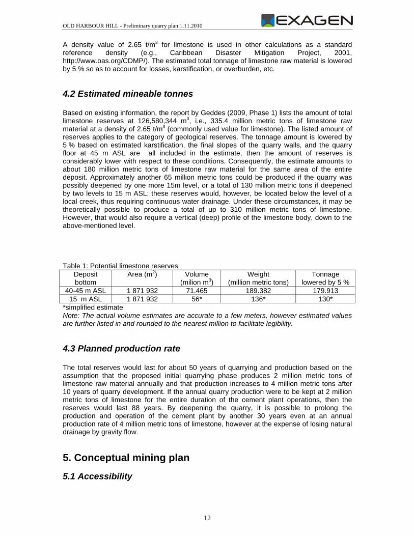
4.2 Estimated mineable tonnes Based on existing information, the report by Geddes (2009, Phase 1) lists the amount of total limestone reserves at 126,580,344 m3, i.e., 335.4 million metric tons of limestone raw material at a density of 2.65 t/m3 (commonly used value for limestone). The listed amount of reserves applies to the category of geological reserves. The tonnage amount is lowered by 5 % based on estimated karstification, the final slopes of the quarry walls, and the quarry floor at 45 m ASL are all included in the estimate, then the amount of reserves is considerably lower with respect to these conditions. Consequently, the estimate amounts to about 180 million metric tons of limestone raw material for the same area of the entire deposit. Approximately another 65 million metric tons could be produced if the quarry was possibly deepened by one more 15m level, or a total of 130 million metric tons if deepened by two levels to 15 m ASL; these reserves would, however, be located below the level of a local creek, thus requiring continuous water drainage. Under these circumstances, it may be theoretically possible to produce a total of up to 310 million metric tons of limestone. However, that would also require a vertical (deep) profile of the limestone body, down to the above-mentioned level. Table 1: Potential limestone reserves
Deposit bottom
Area (m2) Volume (milion m3)
Weight (million metric tons)
Tonnage lowered by 5 %
40-45 m ASL 1 871 932 71.465 189.382 179.913 15 m ASL 1 871 932 56* 136* 130*
*simplified estimate Note: The actual volume estimates are accurate to a few meters, however estimated values are further listed in and rounded to the nearest million to facilitate legibility.
4.3 Planned production rate The total reserves would last for about 50 years of quarrying and production based on the assumption that the proposed initial quarrying phase produces 2 million metric tons of limestone raw material annually and that production increases to 4 million metric tons after 10 years of quarry development. If the annual quarry production were to be kept at 2 million metric tons of limestone for the entire duration of the cement plant operations, then the reserves would last 88 years. By deepening the quarry, it is possible to prolong the production and operation of the cement plant by another 30 years even at an annual production rate of 4 million metric tons of limestone, however at the expense of losing natural drainage by gravity flow.
5. Conceptual mining plan
5.1 Accessibility
OLD HARBOUR HILL - Preliminary quarry plan 1.11.2010
13
The most suitable access to the area of the future quarry and processing site is from the south from the primary road Kingston – Montego Bay, or by railway (presently out of service), or from the east from the town of Old Harbour. Local roads lead to the eastern and western edges of the Rose Hall elevation. Clarendon Gully flows around the area of the proposed quarry from the east, Marmee Gully from the west, and both in a N-S direction at an elevation between 25-35 m ASL. The geomorphology is quite varied, and the western and eastern slopes are fairly steep. A developed quarry, which is considered to be suitable for the new development, lies in the southeastern part of the area. The quarry development and quarry access roads should start from and the processing plant should be located in the east and at the eastern edge of the Rose Hall (Old Harbour Hill) elevation due to the relatively densely populated western edge of the area in question and due to a steeper slope rise from the west. The access to the future quarry area from the east was chosen as it is considered to be ideal with regard to the aim of the plan. The placement of the primary crushing and screening technology is proposed at the eastern border of the extracted section in the square J5 (see fig. 2). A non-quarried buffer zone at the southern part of the Rose Hall elevation was chosen with respect to future reclamation and to the fact that it partially separates the quarry area from populated areas and public roads and also preserves the view of Rose Hall elevation from the south. The non-quarried section of the deposit in the south is referred to as the „buffer“. The western and southern edges of the potential quarry area are by far more densely populated (also more homes on the slopes of the Rose Hall elevation and Old Harbour Hill) and that is why these areas were, if possible, not included in the area of the potential quarry. The operating areas were proposed to be located in the eastern part of the area for the very same reason.
5.2 Mining process description In order to estimate the total volume of limestone reserves in the delineated area and in the area after deposit exhaustion, the lowest quarrying level of 40 (45) m ASL was chosen, which still allows for the quarry area to be drained by gravity flow into the surrounding gully. The final quarry floor of the deposit is proposed to slope slightly by 2.5 % from a level of 45 m ASL in the west and from 40 m ASL in the east toward Calderon Gully (the lowest part of the area). Extending the quarry westwards beyond the current water divide shall pose no significant problem for the drainage of the whole quarry towards the east. The bases of higher quarry benches should be horizontal. In order to estimate the tonnage of limestone raw material a density of 2.65 t/m3 was used, and the total volume of reserves was lowered by 5 % (karstification – hollows with and without infill, superficial karstification, etc.). The level of individual quarry benches were determined with regard to the bottom of the deposit, to quarry face heights of 15 m and to the geomorphology, and after testing several other options and possibilities. Thus, the quarry bench levels in the proposed quarry were chosen as follows: 45, 60, 75, 90, 105 m ASL. The peripheral areas of the lowest level would drop to 40 m ASL in the east so as to drain the entire quarry area in the direction of Clarendon Gully (elevation of about 25 m ASL). The quarry opening is proposed in four scenarios (options). Option 2, which is the main alternative, is further elaborated and Options 1, 3 and 4 are purely informative.
OLD HARBOUR HILL - Preliminary quarry plan 1.11.2010
14
The eastern part of the deposit, with a relatively homogeneous limestone quality and high CaCO3 (84-99%) and low MgCO3 content, ranks as the most favourable according to initial information regarding the composition of raw materials from surface samples. The loosening of the solid to hard limestones is expected to be done by bench blasting. The initial financial investment for development of the quarry and quarry faces(benches), and for construction of quarry roads is usually high. As a result, the project plan attempts to spread out the costs over a longer period (Option 1, 2 – see below). Because other circumstances, possibilities and requirements regarding the future quarry are not known, the initial development was proposed in several alternatives that can be combined. In order to reach the required production level of 2 million metric tons of limestone annually the choice of an initial time frame of 1-3 years, with gradually increasing production, is considered to be suitable. After the proposed initial deposit development, production is proposed to increase to 4 million metric tons annually of limestone raw material after about 10 years. The main haul road divides the deposit area into southern and northern parts. Primarily the southern part is the subject of the quarry proposal. The northern part of the deposit, which would be quarried after the southern part is exhausted, is dealt with on a bench-by-bench basis. The experience gained from the southern part of the deposit will be applied later on during development of the northern area.
5.3 Overburden stripping and pile and re-utilizing The overburden volume shall not exceed 1 million cubic metres. Considering the characteristics of the surface, it is expected that only the vegetation cover will have to stripped. In cement production, it is usually possible to process the superficial karstified limestone sections, which are contaminated with loam or clay; they are often a desired admixture because they lower the amount of clay and silica that has to be supplied for corrective purposes. The same applies to karst hollows filled with karst loam. It is only necessary to take the change in chemical composition into account and to modify the composition of the mixture of cement raw materials accordingly.
5.4 Blasting and Ripping It is assumed that the solid to hard limestones will be loosened by blasting in the form of several standard bench blasts. Blasting shall be used as the basic approach whereby ripping may be applied as a supporting method. If adequate quarry development is achieved with a long quarry face, then it is possible to even consider single row blasts, which usually consume fewer explosives. It is assumed that the effect of individual bench blastings will amount to 20-40 thousand metric tons once to twice per week, at full annual production capacity of 2 million metric tons as planned. The frequency of the bench blasts should double or increase in size after quarry production is expanded and increased to 4 million metric tons annually. A bench blasting diagram is shown on the following pages
OLD HARBOUR HILL - Preliminary quarry plan 1.11.2010
15
5.5 Bench design and construction The proposed limestone quarrying should involve 5 horizontal benches a 15 m quarry face height and a 75° slope. The values used for the limestone quarrying have proved successful in a number of countries and are commonly used. The quarry face height is usually based on the technical possibilities of the drilling technology used to prepare for bench blasting, on requirements regarding the fragmentation of the blasted rocks, and on safety instructions for the loading of raw material. The slope of the quarry face is basically based on the angle of the drill holes used to prepare for bench blasting. The quarry faces are proposed to set back at least 25 m (working terrace width) for safe operation of loading and hauling equipment. Proposed quarry development - bench levels Bench 5 105 m ASL Bench 4 90 m ASL Bench 3 75 m ASL Bench 2 60 m ASL Bench 1 45 m ASL* *slopes slightly from 45 m ASL in the west to 40 m ASL in the east The proposed quarry floor slopes slightly from 45 m ASL in the west to about 40 m ASL in the east in order to drain the quarry. It is possible to use temporary surface drains (gutters) if percolation and runoff of rainwater from higher benches is inadequate.
5.6 Haul road and haulage A main haul road is proposed so as to provide access to individual quarry benches mainly in the southern part of the deposit. However, it should also be used for quarrying operations in the northern part of the area. The main haul road divides the deposit area into a southern and northern part. It is assumed that the southern part will be quarried out first, and only then followed separately by the northern area. The road width should be 10 m. It is assumed that the blasted rocks will be hauled by high-capacity dump trucks. The main haul road should serve for hauling blasted rocks and also any potential unsuitable layers and overburden. Therefore, a dump for any potential unusable materials is located near the road. The proposed route of the main haul road is also based on the chosen location of the processing technology section so as to minimize the length of haul roads. It is necessary to consider the geomorphology of the terrain when proposing the route so as to limit the road gradient.
5.7 Processing specification and location The location of a permanent preliminary crusher and related processing equipment is proposed at the eastern edge of the extraction zone. The feed spout of the preliminary crusher should be located at the edge of this site with a ramp from above connected to the quarry roads. The processing equipment setup shall enable the following basic specifications of the material input and output: • Limestone feed size : 1,200 mm X 1,200 mm X 1,200 mm
OLD HARBOUR HILL - Preliminary quarry plan 1.11.2010
16
• Limestone Outlet:size : Less than 100 mm in 90% The crushed mixture of limestone and clay will be delivered to cement plant via a belt conveyor from the limestone crusher to the limestone/clay preblending pile. The alternative solution of using mobile crusher and subsequent belt conveying is basically possible. However, due to local conditions, it would probably be suitable only during the quarrying of the northern part of the deposit.
5.8 Proposed location of processing equipment and raw material stockpiles (crushing area and stockpile) The location of primary crushing plant and further technology is proposed in the basic scenario at the eastern edge of the extraction zone. The feeder of the primary crusher is proposed at the edge of this area with entrance access in connection to quarry roads. The loading plant for the belt conveyor towards the cement plant shall be placed between the primary crushing plant and the belt conveyor.
5.9 Crushing with clay and product delivery by belt conveyor To achieve suitable fragmentation, it is assumed that the crushing of limestone will be executed by hammer crusher. Separate equipment will be used to prepare Al and Si corrective additives prior to homogenization. Covered belt conveyors are proposed for conveying material between individual processing stations, and their capacity will be based on the amount of individual components used in the mixture.
5.10 Clay shipping in and storage area The extracted clay material shall be delivered to the quarry technology zone by trucks directly to the independent feeder of the crusher. Direct delivery and controlled loading of the raw material mix together with the cement grade limestone into one crushing line is proposed. This will enable the pre-homogeneization of the raw material mix already at the stage of primary crushing.
5.11 Mining facility equipment and location The essential quarrying equipment for loosening raw material (drilling equipment, explosives), and for loading and hauling blasted rocks is proposed based on the required production capacity and on local conditions. For information purposes, it is possible to propose the following: Initial phases with single-shift operations producing up to 2 million metric tons of limestone, i.e. about 40 thousand metric tons per week 2 drilling rigs 4-6 60 ton capacity dump trucks 3 front-end loaders The above-listed equipment should be approximately doubled after increasing production capacity to 4 milion metric tons. More hauling equipment will be required as the distance from the quarry face to the crusher increases.
OLD HARBOUR HILL - Preliminary quarry plan 1.11.2010
17
In addition to qualified equipment operators and servicing (fuel, repairs, transport of explosives, etc.), it will probably also be necessary to provide equipment so as to fragment boulders (jackhammer), and possibly other equipment.
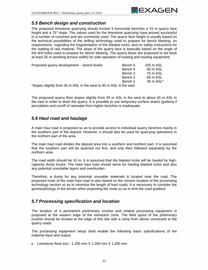
Figure: primary crushing
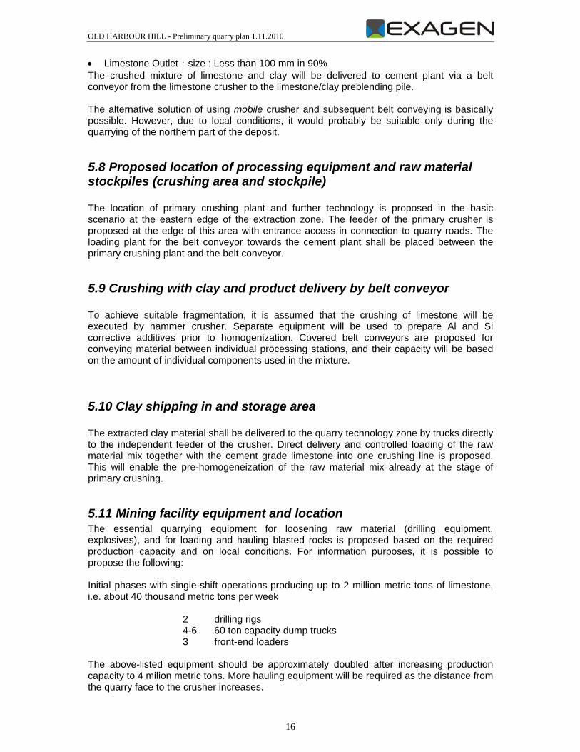
The quarry will serve exclusively as a supply base for the proposed CEMCORP cement plant. After loading of fragmented rock, the material shall be transported by large-capacity trucks (dumpers) to the processing by means of crushing (by hammer crusher) to the required output size. From here, the processed raw material shall be transported by the belt conveyor to further processing at the cement plant.
Figure: belt conveyor
The quarry facilities shall also comprise of • administrative office budilding (offices, changing rooms, showers, hygienic toilets etc.); • background facilities, such as workshop, spare parts storage; • storage of machine fuels, fuelling station, storage of machine lubricants; • secure parking area of cars and mobile equipment (mostly dumpers and loaders, other
vehicles);
The amount and intensity of applied machinery shall depend on the required capacity of the quarry. According to the available information, the yearly production during the initial 6 – 8
OLD HARBOUR HILL - Preliminary quarry plan 1.11.2010
18
years shall no exceed 2 million tons. In the following years the production shall increase to the proposed 2 million tons p.a. Following quarry technology shall be used for the assumed initial production capacity of 2 million tons p.a.: • 2 drill rigs for preparation of blasting, monitoring of deposit structure as well as monitoring
– bucket capacity 18 – 35 m3); • 1 rock demolition hammer on the excavator undercarriage for disintegration of excessive
rock blocks. The proposed machinery assumes 1 shift operation 5 days a week. The amount of machinery shall approximately double after increase of production to 4 million tons p.a. The transport distance between rock extraction location and the primary crushing feeder as well as the possibilities to work in higher intensity (e.g., evening and weekend shifts) have to be taken into consideration. These parameters influence the setup of applied technology.
5.12 Production and development schedule
5.12.1 Production schedule For now, the quarrying and subsequent production schedule is set roughly at an annual production rate of 2 million metric tons of limestone and, after quarry and production expansion, at 4 million metric tons annually. It is assumed that a 2-3 year period is necessary for commencement and initial development of production and that production will subsequently stabilize at 2 million metric tons of limestone raw material per year
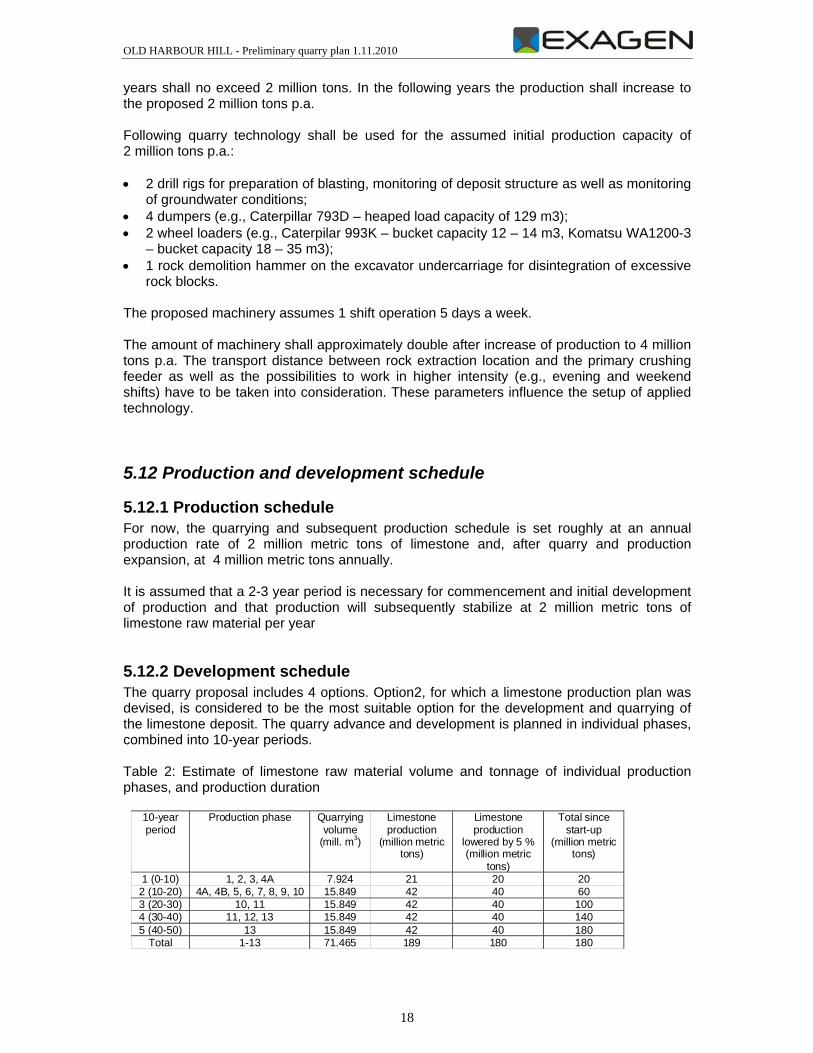
5.12.2 Development schedule The quarry proposal includes 4 options. Option2, for which a limestone production plan was devised, is considered to be the most suitable option for the development and quarrying of the limestone deposit. The quarry advance and development is planned in individual phases, combined into 10-year periods. Table 2: Estimate of limestone raw material volume and tonnage of individual production phases, and production duration
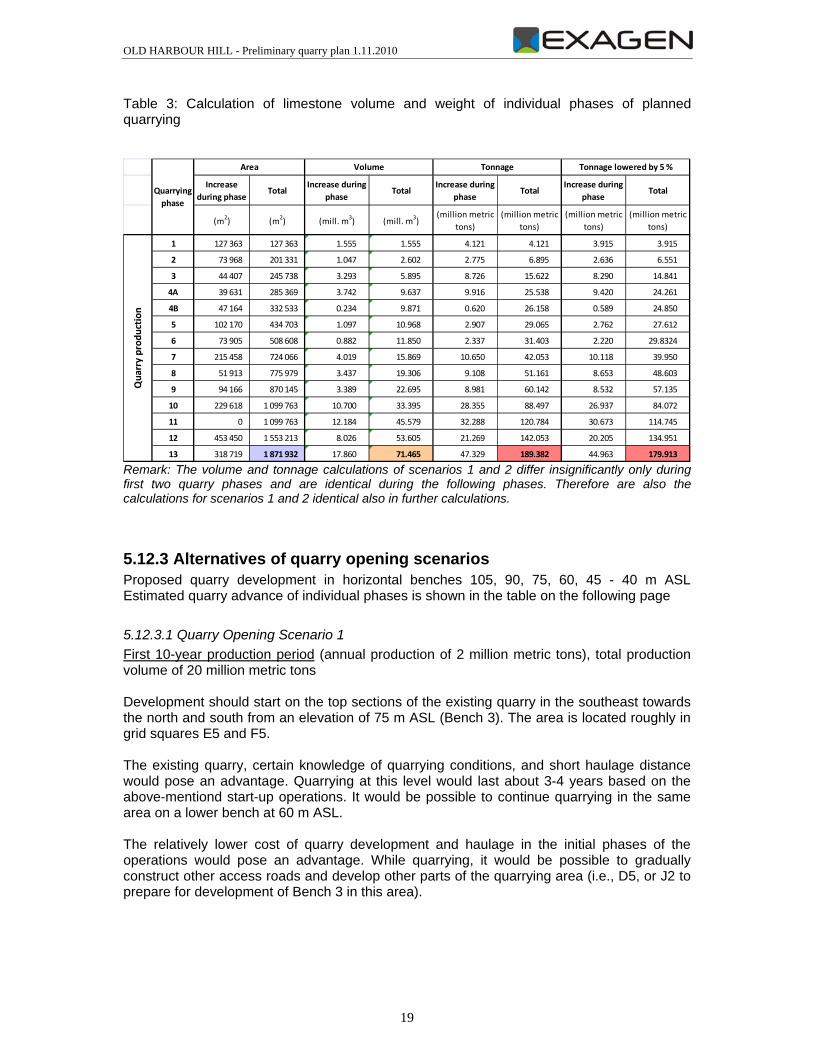
Remark: The volume and tonnage calculations of scenarios 1 and 2 differ insignificantly only during first two quarry phases and are identical during the following phases. Therefore are also the calculations for scenarios 1 and 2 identical also in further calculations.
5.12.3 Alternatives of quarry opening scenarios Proposed quarry development in horizontal benches 105, 90, 75, 60, 45 - 40 m ASL Estimated quarry advance of individual phases is shown in the table on the following page
5.12.3.1 Quarry Opening Scenario 1 First 10-year production period (annual production of 2 million metric tons), total production volume of 20 million metric tons Development should start on the top sections of the existing quarry in the southeast towards the north and south from an elevation of 75 m ASL (Bench 3). The area is located roughly in grid squares E5 and F5. The existing quarry, certain knowledge of quarrying conditions, and short haulage distance would pose an advantage. Quarrying at this level would last about 3-4 years based on the above-mentiond start-up operations. It would be possible to continue quarrying in the same area on a lower bench at 60 m ASL. The relatively lower cost of quarry development and haulage in the initial phases of the operations would pose an advantage. While quarrying, it would be possible to gradually construct other access roads and develop other parts of the quarrying area (i.e., D5, or J2 to prepare for development of Bench 3 in this area).
OLD HARBOUR HILL - Preliminary quarry plan 1.11.2010
20
5.12.3.2 Quarry Opening Scenario 2 – Main Scenario The quarry opening is proposed from the area of the planned crusher and processing plant location in the north towards the south from the elevation level of 75 m ASL (3rd bench level) in the square G5 (see figure 2). The extraction shall progress towards the south. After excavation of the bench level 3 the excavation shall continue to the 2nd bench level at 60 m ASL in the same direction from the north to the south. The final phase of the first period is Phase 4A (Bench 1 at an elevation of 40-45 m ASL). Major advantage of this scenario is the location of the primary crusher in the central section of the quarry area which will be well accessible during the whole duration of the quarry, also from the northern part of the quarry area. This shall eliminate the haulage distance from the quarry walls to the feeder. The second feeder shall be continually supplied by the clay correction material and the material mix shall proceed to the crusher for the first homogeneization. Haul roads shall be developed along with the subsequent development of the quarry after the quarry opening. After the crushing follows direct haulage to the cement plant by the belt conveyor.
5.12.3.3 Quarry Opening Scenario 3 Development should commence from the area of grid square J2, from an elevation of 75 m ASL toward the south (Bench 3) and involves the construction of a main haul road into this area already in the initial phases. Then, other roads would also be necessary leading roughly to area G2 for other development work at an elevation of 90 m ASL (Bench 4) and subsequently to area F2 to an elevation of 105 m ASL (Bench 5). Progression of other phases is as follows: 4B, 5, 6, 7, 8, 1, 2, 9, 10, 3, 11, 4A, 12, 13.
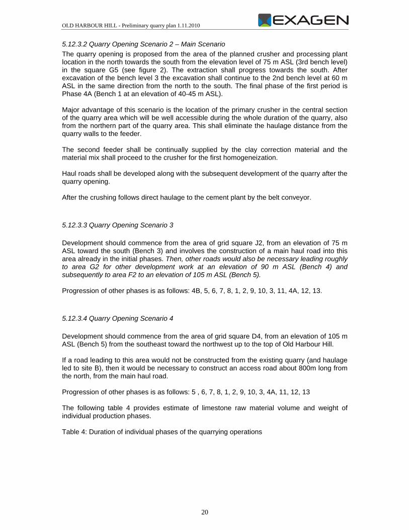
5.12.3.4 Quarry Opening Scenario 4 Development should commence from the area of grid square D4, from an elevation of 105 m ASL (Bench 5) from the southeast toward the northwest up to the top of Old Harbour Hill. If a road leading to this area would not be constructed from the existing quarry (and haulage led to site B), then it would be necessary to construct an access road about 800m long from the north, from the main haul road. Progression of other phases is as follows: 5 , 6, 7, 8, 1, 2, 9, 10, 3, 4A, 11, 12, 13 The following table 4 provides estimate of limestone raw material volume and weight of individual production phases. Table 4: Duration of individual phases of the quarrying operations
OLD HARBOUR HILL - Preliminary quarry plan 1.11.2010
5.12.3.5 Quarry development after the initial stage The quarry development after first 10 year stage is identical for scenarios 1 and 2. Second 10-year production period (annual production of 4 million metric tons), total production volume of 40 million metric tons (total production volume of 60 million metric tons since start-up) While completing quarrying operations in the first period in Phase 4A, quarrying should commence in grid square J2 on Bench 3 at an elevation of 75 m ASL and continue by developing Bench 5 at the top northeastern part of Old Harbour Hill from grid square G2, F2 (Phase 5), and the entire bench should be developed for quarrying (Phase 6). Work should then continue in the same area on the lower Bench 4 at an elevation of 90 m ASL (Phase 7) and on the even lower Bench 3 at 75 m ASL (Phases 8, 9), and quarrying should commence on Bench 2 at an elevation of 60 m ASL (Phase 10). The second production period is demanding because of a large amount of quarrying in superficial sections. It would, therefore, be suitable to commence quarrying preparations and construction of haul roads already during the first period of work. Third 10-year production period (annual production of 4 million metric tons), total production volume of 100 million metric tons since start-up Quarrying should continue in the area of Phase 10 at an elevation of 60 m ASL of Bench 2 and commence on Bench 1 at an elevation of 40-45 m ASL (Phase 11). Fourth 10-year production period (annual production of 4 million metric tons), total production volume of 140 million metric tons since start-up Quarrying should continue in the area of Phase 11 at an elevation of 45 m ASL of Bench 1, commence in the northern area on Bench 3 at an elevation of 75 m ASL (Phase 12) and continue on the lower benches (Phase 13). Fifth 10-year production period (annual production of 4 million metric tons), total production volume of 180 million metric tons since start-up
OLD HARBOUR HILL - Preliminary quarry plan 1.11.2010
22
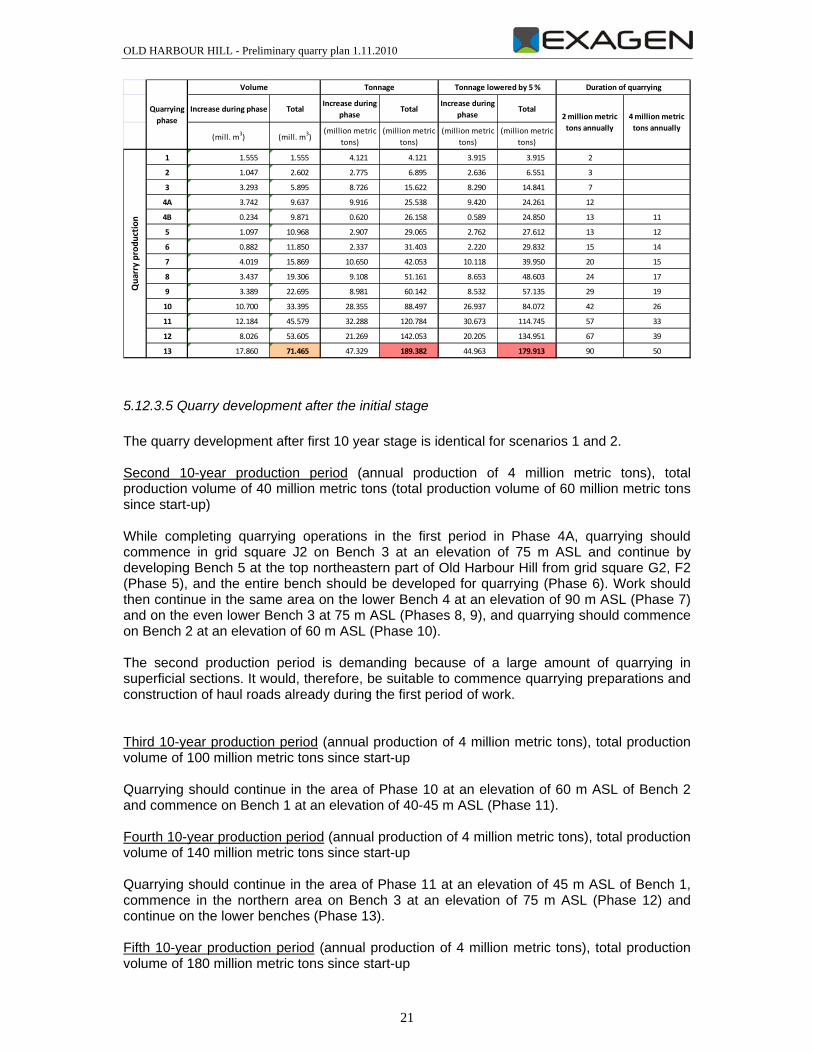
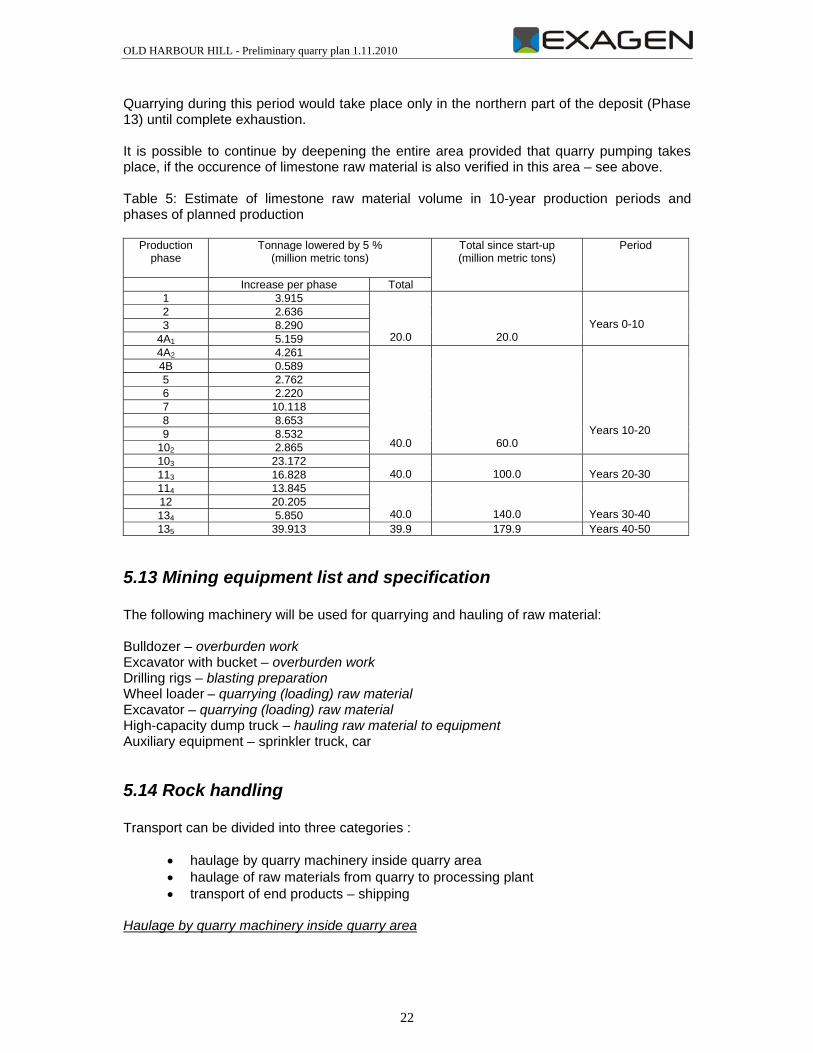
Quarrying during this period would take place only in the northern part of the deposit (Phase 13) until complete exhaustion. It is possible to continue by deepening the entire area provided that quarry pumping takes place, if the occurence of limestone raw material is also verified in this area – see above. Table 5: Estimate of limestone raw material volume in 10-year production periods and phases of planned production
5.13 Mining equipment list and specification The following machinery will be used for quarrying and hauling of raw material: Bulldozer – overburden work Excavator with bucket – overburden work Drilling rigs – blasting preparation Wheel loader – quarrying (loading) raw material Excavator – quarrying (loading) raw material High-capacity dump truck – hauling raw material to equipment Auxiliary equipment – sprinkler truck, car
5.14 Rock handling Transport can be divided into three categories :
• haulage by quarry machinery inside quarry area • haulage of raw materials from quarry to processing plant • transport of end products – shipping
Haulage by quarry machinery inside quarry area
Production phase
Tonnage lowered by 5 % (million metric tons)
Total since start-up (million metric tons)
Period
Increase per phase Total 1 3.915
20.0
20.0
Years 0-10
2 2.636 3 8.290
4A1 5.159 4A2 4.261
40.0
60.0
Years 10-20
4B 0.589 5 2.762 6 2.220 7 10.118 8 8.653 9 8.532
102 2.865 103 23.172
40.0
100.0 Years 20-30 113 16.828
114 13.845
40.0
140.0
Years 30-40
12 20.205 134 5.850 135 39.913 39.9 179.9 Years 40-50
OLD HARBOUR HILL - Preliminary quarry plan 1.11.2010
23
Haulage will take place only inside the quarrying area. The quarry machinery will not exit the quarrying area and will only use quarry roads. Quarry roads will be constructed and drained so as to accomodate the tonnage and size of the quarry machinery used. Haulage inside the quarry area will also include haulage of overburden materials to dumps located near the quarrying area. The machinery used will not exit the delineated quarrying area. High-capacity dump trucks will be used to haul the overburden from stripping operations. Haulage of raw materials from quarry to processing plant A sealed main haul road will be constructed to allow for haulage of raw materials from the quarrying area to the processing plant. It is also possible to consider the option of using belt conveyors. Their use will depend on economic aspects and on the final location of the processing equipment in relation to the quarrying area. Haulage between the quarry area and the processing plant will be provided by high-capacity dump trucks on two-way roads. Transport of end products – shipping The technical facilities will include storage areas for end products. A weigh bridge will be used. The products will be shipped in accordance to shipping regulations and with relevant documents (weight certificate, delivery order, invoice, certificate, etc.).
5.15 Grade control As part of performance supervision, the company will maintain, update and store documents regarding the production work conducted. The work shall include: Geodetic surveying of the advance of quarry faces, of karst hollows and features, and
other geological features so as to record any significant changes in the geomorphology and quality of the deposit and any other features, which may affect the safety of operations and the quality of the quarried raw material
- Geodetic measurements will be made and evaluated by an authorized mine surveyor
sampling of rocks from holes for blasting, or from the quarry face, rubble, etc.
drilling and sampling holes so as to provide detailed information on the
chemical/technological properties of the raw material - Sampling holes shall be made expediently, only in essential cases and
areas, when information regarding raw material quality is insufficient or contradictory. The holes will be made with drilling equipment used for blasting preparations. The location, number of holes, length, sampling method and sample evaluation will be determined in individual cases by authorized workers.
maintaining a record of changes in reserves and of the quality of the quarried raw material
- Regular evaluations of the amount and quality of the quarried mineral
OLD HARBOUR HILL - Preliminary quarry plan 1.11.2010
24
- The quality of the quarried raw material is monitored continuously during the course of blasting operations, by sampling holes made for blasting
documenting quarry faces In the case that features and changes in the properties of the rocks are detected, which may affect the safety of operations or which influence the geomorphology and quality of the deposit considerably, then they will be recorded, documented and assessed.
5.15.1 Delineation The delineated limestone reserves in the designated area are marked off by a contour line depicting the proposed extent of reserves designated for quarrying – see appended maps.
5.15.2 Data update The current data regarding the reserves are based on the proposed spatial model of the quarry, therefore the same also applies to the delineation of the blocks of reserves.
5.15.3 Grade estimation The amount of limestone reserves was determined based on a constructed spatial model of the terrain and on the projected delineation of the proposed future quarry. The volume estimate is methodically highly accurate. However, the initial estimate model corresponds to the initial 1:12,500 scale map in terms of accuracy. The estimate method is entirely suitable for the given purpose of determining the amount of reserves.
5.15.4 Mining block definition The deposit area was divided into mining blocks for each individual bench, or its parts.
5.16 Mining support services
5.16.1 Mining dedust During dry periods, potential dust problems will be avoided by watering the haul roads and washing down machinery so as to minimize dust nuisance. The crushing and sorting areas will be enclosed, and a mist system will be installed in open areas of the operations.
5.16.2 Compressed air distribution Compressed air distribution is not proposed.
6. Reclamation and closure plan All equipment used in production, material haulage as well as auxiliary operations will be eliminated. Reclamation of the area after production is terminated will depend on the intended end use of the area. It is realistic to assume that a relatively large area of exposed bedrock (about 2 km2) will be created. In view of the relatively good road access and assumed good foundation conditions, the area may be used, for example, as building plots
OLD HARBOUR HILL - Preliminary quarry plan 1.11.2010
25
for construction of industrial facilities or for residential development. The bedrock will probably have to be broken up and resoiled for planting of trees and other vegetation, if biological reclamation of the quarry area is requested. The area may theoretically also be broken up by shallow bodies of water, which would however require additional landscaping.
6.1 Magazine for explosives The magazine for explosives will be eliminated after the termination of quarrying operations.
6.2 Structure to be dismantled and levelled A relatively level area sloping slightly to the east is expected to be created, which may be developed based on intended end use after production is terminated.
6.3 Structure to be retained The access roads should be retained if the intended end use, chosen for the area after terminating production, is suitable.
6.4 Maximum 3:1 slope The remnant slope of the rock wall will be modified to create an overall slope of 1:3 by adding fill to the foot of the slope and tearing down steeper wall sections. In addition, a talus slope of about 35° will accumulate naturally at the foot of the wall.
6.5 Sink hole, streams and drains A level area, without large uneven sections, will remain after quarrying is terminated.
OLD HARBOUR HILL - Preliminary quarry plan 1.11.2010
26
7. Conclusion and recommendations The submitted Preliminary Quarry Plan regarding the exploitation of the limestone deposit for use in cement production, the quarrying plan and the location of processing equipment provides sufficient information as a part of the Environmental Imapct Assessment procedure. The proposed conception of the quarry development and actual limestone extraction is the necessary prerequisite for the operation of the proposed cement plant. The cement grade limestone at the Old Harbor Hill deposit represents the major part of the composition of the cement raw material mix – about 75% of the total. The proposed Preliminary Quarry Plan is a compromise solution with the aim of extraction of sufficient amount of cement grade limestone raw material to achieve reasonable rate of return of high investment into the quarrying and production technologies for the cement plant and of minimizing the environmental and social impact of the quarry at the same time. The quarry and raw material mix processing concept is based on the location of primary crusher and of the limestone and the clay feeder. Joint crushing of limestone and clay results in initial homogeneization of the raw material. The processed raw material is ready for transport by belt conveyor to the cement plant. The location of the crusher at the eastern edge of the central part of the quarry area enables the utilization and accessibility of the technology during the whole duration of the quarry operation. It eliminates the haulage distance to the crusher and the belt conveyor loading respectively. The total tonnage of the proposed 180 million tons of recoverable reserves provides sufficient amount of raw material for approximately 50 years of cement plant operation even under the assumption of the increased yearly production of 4 million tons. The Preliminary Quarry Plan also respects the necessity of quarry drainage by modelling of slightly inclined quarry floor towards the Clarendon Gully. The proposed quarry development method is in benches 15 meters high and initial rock disintegration by blasting. The disintegrated rock is handled by loaders and hauled by dumpers. The quarry area shall be rehabilitaded already during the consequent extraction of the deposit raw material and after quarry closure. The way of rehabilitation shall respect the final decision of land use after the quarry closure (see map in the Appendix 8). The quantification of exploitable limestones is a realistic basis for other purposes. For such a demanding goal with respect to investment, it is in the investor´s best interest to supplement the initial data in order to be able to select the optimum quarrying and production equipment. The Preliminary Quarry Plans deals with a project involving long-term production of high-quality cement, and possibly other affiliated production operations. The Preliminary Quarry Plan shall serve as a fundamental model in considering and deciding on a final solution with respect to investment and other aspects.