Pioneering for You Wilo-EMU FA+T-Motor 6073122 Ed.03-07/2015 WH US Installation and operating instructions fr Notice de montage et de mise en service es Instrucciones de instalación y funcionamiento
Transcript
Pioneering for You
Wilo-EMU FA+T-Motor
6073122 Ed.03-07/2015 WH
US Installation and operating instructionsfr Notice de montage et de mise en servicees Instrucciones de instalación y funcionamiento
Fig. 1: T 20.1 Fig. 1: T 49, T 50, T 50.1, T 56, T 57, T 63.1, T 63.2, T 72
Fig. 1: T 12, T 13, T 17, T 17.2, T 20 Fig. 1: T 24, T 30, T 34, T 42
P-Typ M-Typ
S/N MFY
U Q IMø
I H OTS/E
IST Cos TPF max
P SF
F ISF IP
N MC
1 1
3
4
6
7
8
9
10
P-Typ M-Typ
S/N MFY
U Q IMø
I H OTS/E
IST Cos TPF max
P SF
F ISF IP
N MC
1
3
4
6
7
8
9
10
1
2
3
4
6
7
8
9
10
1
2
1
3
5
6
7
8
9
Fig. 2
21
Fig. 3.1 Fig. 3.2
1
3
2x
4
2
Fig. 3.3 Fig. 3.4
Fig. 5 Fig. 6
1
5
66
33
4
2
S1
S1/S2
7a
7b
1
4
8
3
3 6
5
2
7
Fig. 4
1
1
5
9
6
3
4
2
S1
S1/S2
8
7b
7a
d
min
. 2 x
d
min
.0,
5 x
dm
in. 1
x d
A
dm
in.
0,3
x dB
Fig. 8Fig. 7
Fig. 11 Fig. 12Fig. 9 Fig. 10
M 3~
gn-y
e
WVUPE DK
M 3~gn
-ye
W1V1U1 U2V2W2PE DK
2120
250
V (A
C); 2
,5 A
; cos
φ =
1
2021 22
250
V (A
C); 2
,5 A
; cos
φ =
1
250
V (A
C); 2
,5 A
; cos
φ =
1m
ax. °
C
min
. °C
1110
DIN
440
82
1011 12
DIN
440
82
DIN
440
82
max
. °C
min
. °C
DK K21K20
s
Fig. 13: T 20 Fig. 13: T 20.1Fig. 13: T 17.2
Fig. 13: T 24 Fig. 13: T 30, T 34, T 42 Fig. 13: T 49, T 56
Fig. 13: T 12 Fig. 13: T 13 Fig. 13: T 17
DD
D
D
D-
D+
D-
D+
D- D+
D-
D+
D-D+
Fig. 13: T 50, T 50.1, T 57, T 63.1
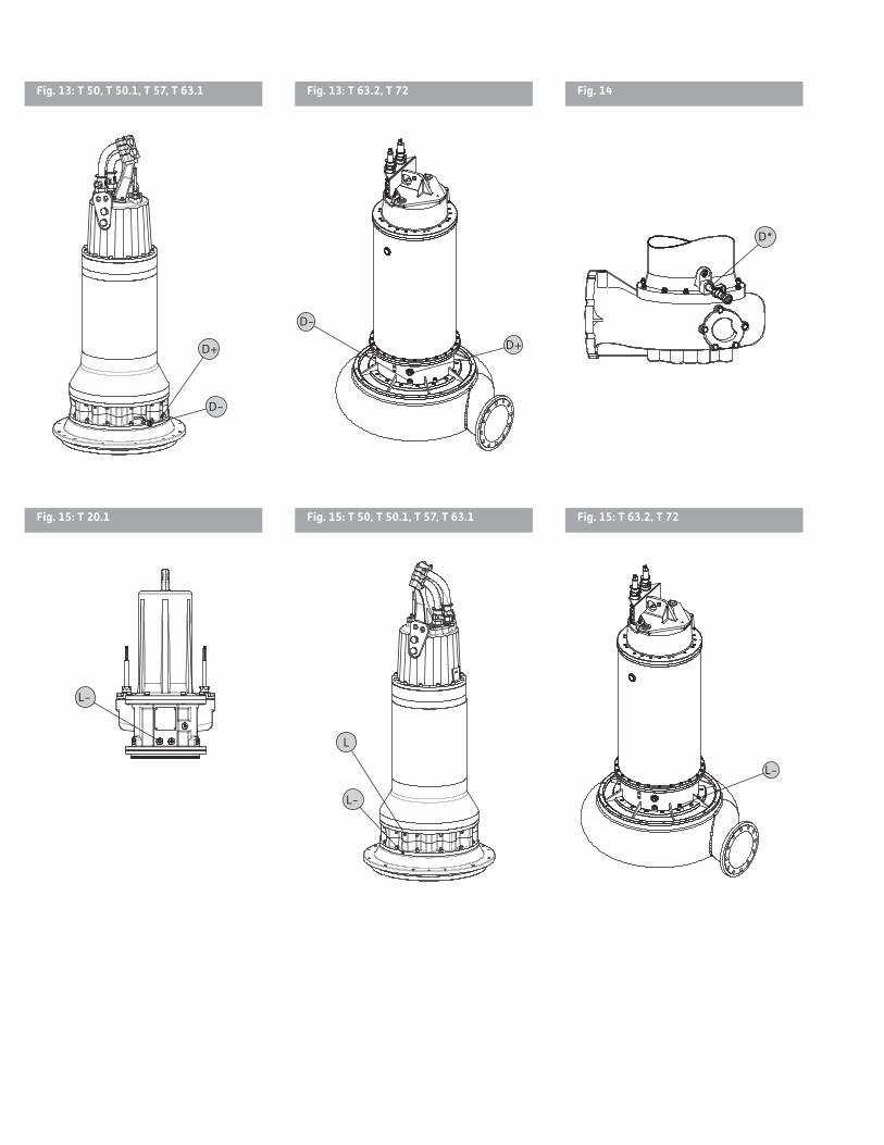
Fig. 15: T 20.1 Fig. 15: T 50, T 50.1, T 57, T 63.1 Fig. 15: T 63.2, T 72
Fig. 13: T 63.2, T 72 Fig. 14
D-
D+
L-
L-
L
D-
D+
D*
L-
Fig. 16: T 50, T 50.1, T 57, T 63.1 Fig. 16: T 49/56 Fig. 16: T 63.2, T 72
F+F
F+
F+
F+
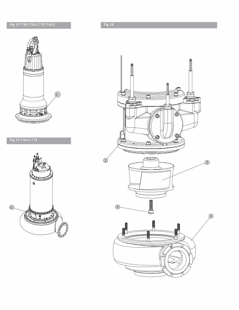
Fig. 17: T 24 Fig. 17: T 30, T 34, T 42 Fig. 17: T 49, T 56
S-
S-
S-
Fig. 17: T 50, T 50.1, T 57, T 63.1
Fig. 17: T 63.2, T 72
S-
S-
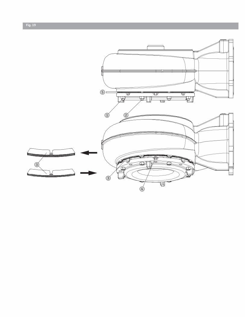
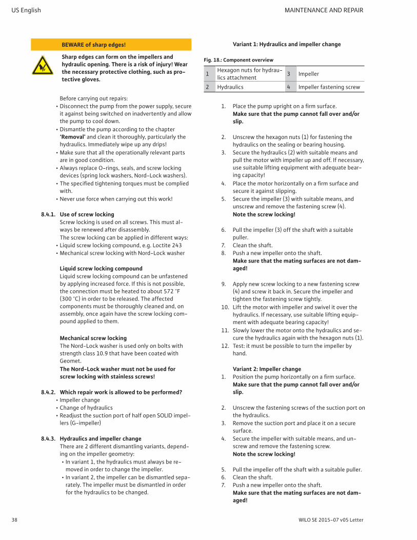
Fig. 18
1
2
3
4
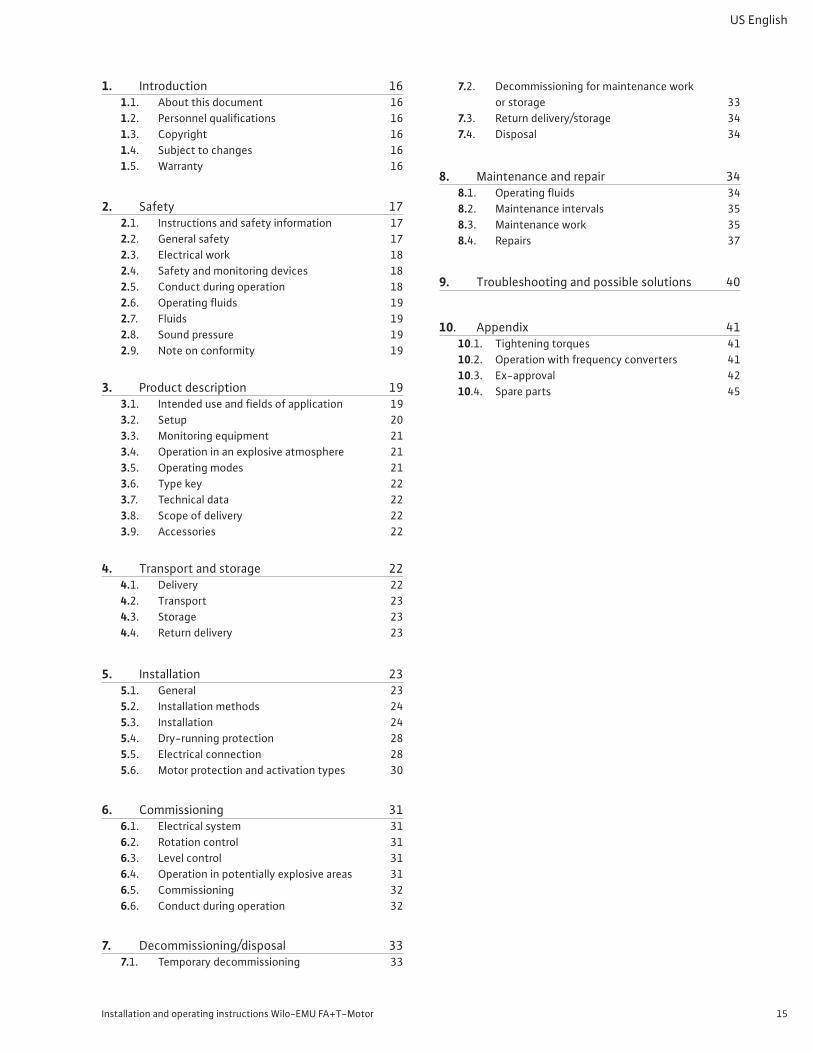
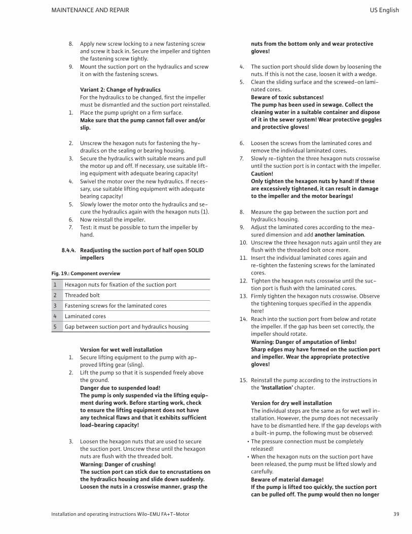
Fig. 19
1
5
4
3
2
3
Installation and operating instructions Wilo-EMU FA+T-Motor 15
US English
1. Introduction 161.1. About this document 161.2. Personnelqualifications 161.3. Copyright 161.4. Subject to changes 161.5. Warranty 16
2. Safety 172.1. Instructions and safety information 172.2. General safety 172.3. Electrical work 182.4. Safety and monitoring devices 182.5. Conduct during operation 182.6. Operatingfluids 192.7. Fluids 192.8. Soundpressure 192.9. Noteonconformity 19
3. Productdescription 193.1. Intendeduseandfieldsofapplication 193.2. Setup 203.3. Monitoring equipment 213.4. Operation in an explosive atmosphere 213.5. Operating modes 213.6. Type key 223.7. Technical data 223.8. Scope of delivery 223.9. Accessories 22
4. Transport and storage 224.1. Delivery 224.2. Transport 234.3. Storage 234.4. Return delivery 23
5. Installation 235.1. General 235.2. Installation methods 245.3. Installation 245.4. Dry-running protection 285.5. Electrical connection 285.6. Motor protection and activation types 30
6. Commissioning 316.1. Electrical system 316.2. Rotation control 316.3. Level control 316.4. Operation in potentially explosive areas 316.5. Commissioning 326.6. Conduct during operation 32
7.2. Decommissioning for maintenance work or storage 33
7.3. Return delivery/storage 347.4. Disposal 34
8. Maintenance and repair 348.1. Operatingfluids 348.2. Maintenance intervals 358.3. Maintenance work 358.4. Repairs 37
9. Troubleshooting and possible solutions 40
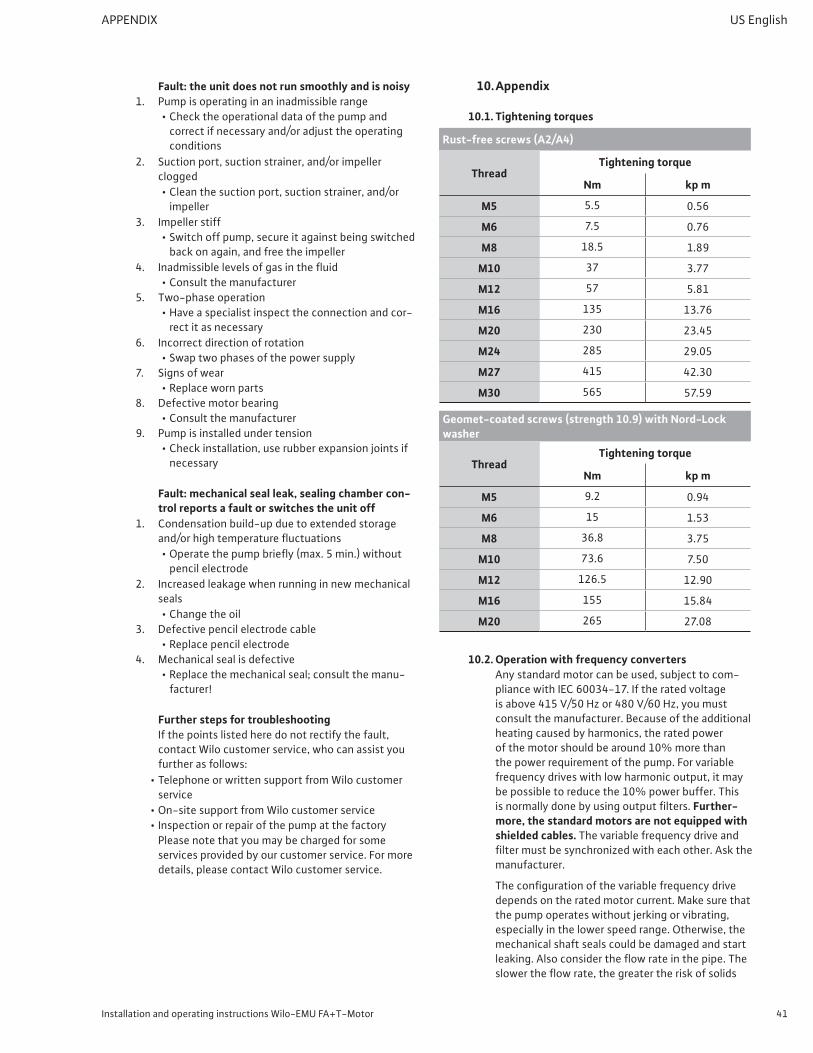
10. Appendix 4110.1. Tightening torques 4110.2. Operation with frequency converters 4110.3. Ex-approval 4210.4. Spare parts 45
16 WILO SE 2015-07 v05 Letter
US English INTRODUCTION
1. Introduction
1.1. About this documentThe language of the original operating instructions is German. All other languages of these instructions are translations of the original operating instruc-tions.The instructions are divided into individual sections, which are listed in the table of contents. Each sec-tion has a heading that clearly describes its content.A copy of the EC declaration of conformity is a com-ponent of these operating instructions.Ifatechnicalmodificationismadeonthedesignsnamed there without our agreement, this declara-tion loses its validity.
1.2. Personnel qualificationsAll personnel who work on or with the pump must bequalifiedforsuchwork;electricalwork,forexample,mayonlybecarriedoutbyaqualifiedelectrician. All personnel must be of legal age.Operating and maintenance personnel must also observe national accident prevention regulations.It must be ensured that personnel have read and understood the instructions in this operating and maintenancemanual;ifnecessary,thismanualmustbe ordered from the manufacturer in the required language.This pump is not intended for use by persons (in-cluding children) with limited physical, sensory, or mental capacities or without the relevant experi-ence or knowledge, unless they are supervised by a person responsible for their safety and receive instructions from that person on how to use the pump.Children must be supervised in order to ensure that they do not play with the pump.
1.3. CopyrightThis operating and maintenance manual has been copyrighted by the manufacturer. The operating and maintenance manual is intended for use by installation, operating, and maintenance personnel. It contains regulations and drawings which may not be reproduced or distributed, either completely or in part, or used for any competitive purpose without the expressed consent of the manufacturer. Illustra-tions may differ from the original and serve only as example illustrations of the pumps.
1.4. Subject to changesThe manufacturer reserves the right to make tech-nicalmodificationstounitsorcomponents.Thisoperating and maintenance manual refers to the pump shown on the title page.
1.5. WarrantyIngeneral,thespecificationsinthecurrent“generalterms and conditions” apply for the warranty.
Any deviations must be contractually agreed and shall then be given priority.
1.5.1. GeneralThe manufacturer is obliged to correct any de-fects found in the pumps it sells, provided that the defects meet one or more of the following require-ments:
• The defects are caused by the materials used or the way the product was manufactured or designed.
• The defects were reported in writing to the manu-facturer within the agreed warranty period.
• The pump was used only as prescribed.• All monitoring devices are connected and were
tested before commissioning.
1.5.2. Warranty periodThe duration of the warranty period is stipulated in the“generaltermsandconditions.”Any deviations must be contractually agreed.
1.5.3. Spare parts, attachments, and modificationsOnly genuine spare parts from the manufacturer may be used for repairs, replacements, attach-ments,andmodifications.Unauthorizedadd-onsandmodificationsortheuseofnon-originalspareparts can seriously damage the pump and/or injure personnel.
1.5.4. MaintenanceThe prescribed maintenance and inspection work should be carried out regularly. This work may only becarriedoutbyqualified,trained,andauthorizedpersonnel.
1.5.5. Damage to the productDamage and malfunctions that endanger safety must be eliminated immediately by trained per-sonnel. The pump may only be operated if it is in perfect working order.In general, repairs should only be carried out by Wilo customer service.
1.5.6. DisclaimerNo warranty claims will be accepted and no liability will be assumed for pump damage if any of the fol-lowing items apply:
• Inadequate dimensioning by the manufacturer due toinsufficientand/orincorrectinformationprovidedby the end user or customer
• Non-compliance with safety instructions and work-inginstructionsasspecifiedinthisoperatingandmaintenance manual
• Improper use• Incorrect storage and transport• Improper assembly/dismantling• Insufficientorincorrectmaintenance• Incorrect repairs• Inadequate construction site or construction work• Chemical,electrochemical,andelectricalinfluences
Installation and operating instructions Wilo-EMU FA+T-Motor 17
SAFETY US English
• WearThis means the manufacturer’s liability excludes all liability for personal injury, material damage, or financiallosses.
2. SafetyThis section lists all the generally applicable safety information and technical instructions. In addition, alltheothersectionscontainspecificsafetyinfor-mation and technical instructions. All instructions and information must be observed and followed during the various phases of the pump’s life cycle (installation, operation, maintenance, transport, etc.). The end user is responsible for ensuring that all personnel follow these instructions and guide-lines.
2.1. Instructions and safety informationThis manual uses instructions and safety infor-mation regarding possible injury and damage to property. To identify them clearly for personnel, the instructions and safety information are distin-guished as follows:
• Instructions appear in bold and refer directly to the preceding text or section.
• Safety information is slightly indented and bold and always starts with a signal word.• Danger
Serious or fatal injuries can occur!• Warning
Serious injuries can occur!• Caution
Injuries can occur!• Caution (instruction without symbol)
Substantial property damage can occur. Irrepa-rable damage is possible!
• Note Additional information on the current topic.
• Safety information that refers to personal injury appears in black and is always accompanied by a safety symbol. Danger, prohibition, or instruction symbols are used as safety symbols.Example:
Dangersymbol:Generalhazard
Danger symbol, for example, electrical current
Prohibition symbol, for example, Keep out!
Instruction symbol, for example, wear protective clothing
The safety symbols used conform to generally ap-plicable directives and regulations.
• Safety information that refers only to material dam-age is printed in gray, without safety symbols.
2.2. General safety• When installing or removing the pump, never work
alone in rooms or sumps. A second person must always be present.
• The pump must always be switched off before any work is performed on it (assembly, dismantling, maintenance, installation). The pump must be dis-connected from the electrical system and secured against being switched on again. All rotating parts must have come to a stop.
• The operator should inform his/her superior imme-diately should any defects or irregularities occur.
• The operator must shut down the equipment im-mediately if defects occur that represent a safety risk. These include:• Failure of the safety and/or monitoring devices• Damage to important parts• Damage to electrical equipment, cables, and
insulation.• Tools and other objects should be kept in their des-
ignated places to ensure they can be used safely.• Sufficientventilationmustbeprovidedwhenwork-
ing in enclosed rooms.• When welding or working with electronic devices,
make sure there is no risk of explosion.• Useonlyliftinggearwhichislegallydefinedassuchandofficiallyapproved.
• The lifting gear must be adapted to the conditions of use (weather, guide system, load, etc.) and be stored carefully.
• Mobile equipment for lifting loads should be used in such a way that it is guaranteed to remain stable during operation.
• When using mobile equipment for lifting non-guid-ed loads, take action to prevent tipping, shifting, sliding, etc.
• Take measures to prevent anyone standing under suspended loads. Furthermore, it is prohibited to move suspended loads over working areas occupied by people.
• If using mobile operating equipment for lifting loads, get a second person to coordinate the proce-dure if necessary (e.g. blocked visibility).
• The load to be lifted must be transported in such a way that no one will be injured if there is a power failure. Furthermore, if such work is being carried out outdoors, it must be canceled if the weather conditions worsen.
18 WILO SE 2015-07 v05 Letter
US English SAFETY
These instructions must be strictly observed. Non-observance can result in injury or substantial material damage.
2.3. Electrical work
DANGER: electrical hazard!
Incorrectly performed electrical work can result in fatal injury! This work may only be carried out by a qualified electrician.
CAUTION: beware of moisture!
Moisture penetrating the cable will damage both the pump and the cable. Never immerse the cable end in fluid and always protect it from moisture. Unused wires must be insulated!
The pumps are operated with single or three phase alternating current. The governing national direc-tives, standards, and regulations as well as the requirements of the local energy supply company must be observed.The person operating the pump must know where it is supplied with power and how to cut off the supply. A motor protection switch must be installed by the customer for three phase AC motors. It is advisable to install a residual-current device (RCD). If there is a possibility that people can come into contactwiththepumpandthefluid(forexampleon construction sites), the connection must be equipped with an additional residual current device (RCD).Thesectionentitled“Electricalconnection”mustbeobserved when connecting the product. The techni-calspecificationsmustbeobservedstrictly.Thepumps must always be grounded.If the pump has been switched off by a protective device, it must not be switched on again until the fault has been eliminated.
When the pump is connected to the electrical con-trol panel, particularly when electronic devices such as soft start control or variable frequency drives are used,theswitchgearmanufacturer’sspecificationsmust be followed to comply with the electromag-netic compatibility (EMC) requirements. Special separate shielding measures (e.g. shielded cables, filters,etc.)maybenecessaryforthepowersupplyand control cables.The connection may only be made if the switch-gear complies with the harmonized EU standards. Cellphones and other mobile radio equipment may cause malfunctions in the system.
WARNING: electromagnetic radiation!
Electromagnetic radiation can pose a fatal risk for people with cardiac stimulators. Affix cor-responding signs to the unit and inform affected persons accordingly!
2.4. Safety and monitoring devicesThemotormaybefittedwiththefollowingmoni-toringdevices,dependingonconfiguration/cus-tomerrequestandmotorsize:
• Motor compartment monitoring• Thermal motor monitor as temperature limit func-
tion (1-circuit temperature monitor) or temperature control and limit function (2-circuit temperature monitor)
• Monitoring of the sealing chamber• Monitoring the leakage chamber• Thermal motor bearing monitoring• Monitoring of the terminal room
For precise information about which monitoring de-vicesarefitted,pleaserefertoyourorderconfirma-tion or the technical data sheet.These monitoring devices must be connected by an electrician and checked to ensure that they function correctly before commissioning.Personnel must be informed about the installed devices and how they work.
Caution!
Never operate the pump if the monitoring de-vices have been removed or damaged, or if they do not work.
2.5. Conduct during operationWhen operating the pump, always follow the locally applicable laws and regulations for work safety, accident prevention, and handling electrical machinery. To help ensure safe working practice, the responsibilities of employees should be clearly specifiedbytheoperator.Allpersonnelarerespon-sible for ensuring that regulations are observed.The pump is equipped with moving parts. During operation, these parts rotate in order to pump the fluid.Certainsubstancesinthefluidcanresultinvery sharp edges forming on the moving parts.
WARNING: rotating parts!
The rotating parts can crush and sever limbs. Never reach into the hydraulics or touch the rotating parts when the machine is in operation.
• Before performing maintenance or repairs, switch off the pump, disconnect it from the power supply, and secure it against being switched on again without authorization.
• Allow the rotating parts to come to a standstill!
Installation and operating instructions Wilo-EMU FA+T-Motor 19
PRODUCT DESCRIPTION US English
2.6. Operating fluids
WARNING: high pressure!
If there is a defect, it is possible for there to be a high pressure of several bar in the sealing cham-ber and leakage chamber. This pressure is dissi-pated through any orifices open during mainte-nance work! Screw plugs opened carelessly can behave like projectiles. To avoid injuries, always comply with the following instructions:
• Always comply with the prescribed sequence of work steps.
• Slowly unscrew the screw plugs, but do not unscrew them completely.
• As soon as the pressure escapes (visible whis-tling or hissing of air), stop turning the screw plug any further. Wait until the pressure has fully dissipated.
Operating fluid can also spray out when the pressure is escaping. Risk of scalding! Only open the screw plugs once the motor has cooled down to ambient temperature. Always wear ap-propriate protective clothing/equipment!
2.7. FluidsEachfluiddiffersinrespectofcomposition,cor-rosiveness, abrasiveness, dry matter content, and in many other aspects. Generally, our pumps can be used for many applications. Please note that if requirements change (density, viscosity, or general composition), this can also affect many parameters of the pump.If the pump is used in or switched over to a different fluid,observethefollowingpoints:
• Thefluidcanbecontaminatedbyoilfromtheseal-ing chamber if the mechanical seal is defective.Use with potable water is not permitted!
• Pumps that have been operated in dirty waste water must be cleaned thoroughly before being used for otherfluids.
• Pumps that have been operated in sewage water containingfecesand/orfluidsthatarehazardoustohealth must be decontaminated before being used withotherfluids.Clarification must be sought as to whether the pump can be used with another fluid at all.
2.8. Sound pressureDependingonthesizeandperformance(kW)ofthepump, it has a sound pressure level of approximately 70 dB (A) to 110 dB (A) during operation.
However, the actual sound pressure level depends on several factors. These include, for example, the installationdepth,installationmethod,fixationofaccessories and piping, the duty point, immersion depth, etc.We recommend that the end user takes an addition-al measurement at the workplace once the pump is running at its duty point and under all operating conditions.
CAUTION: Wear ear defenders!
According to applicable laws and regulations, ear protection must be worn if the sound pres-sure level is 85 dB(A) or more. The end user is responsible for ensuring compliance with this regulation.
2.9. Note on conformityThis product was developed and manufactured in accordance with the applicable EU product direc-tives, to which all products sold in the EU must conform.This product therefore complies with the relevant, general safety and health requirements of the European Union, as well as the published European standardsandinternationallyrecognizedGermanstandards.Since this product was not intended to be sold and used in the European Union, it does not have a CE marking.It is therefore not permitted to sell it in the Euro-pean Union.
3. Product descriptionThe pump is manufactured with great care and is subject to constant quality controls. Trouble-free operation is guaranteed if it is installed and main-tained correctly.
3.1. Intended use and fields of application
ELECTRICAL hazard
When using the pump in swimming pools or other basins that can be entered, there is a risk of electrocution. Note the following:
• Use is strictly forbidden if there are people in the pool or basin!
• If there are no people in the basin, protective measures must be taken according to the na-tional regulations.
20 WILO SE 2015-07 v05 Letter
US English PRODUCT DESCRIPTION
DANGER: explosive fluids!
Pumping explosive fluids (e.g. gasoline, kero-sene, etc.) is strictly prohibited. The pumps are not designed for these fluids!
Wilo-EMU FA… submersible pumps with T motor are suitable for intermittent and continuous duty with thefollowingfluids:
• Drainage and sewage• Sewage containing feces• Municipal and industrial wastewater• Sludges with up to 8% dry matter (depending on
pump type)from pump chambers and tanks.The submersible pumps must not be used for pumping the following:
• Potable water• Fluids containing hard components such as stone,
.Intended use also includes compliance with these instructions. Any other use is regarded as improper use.
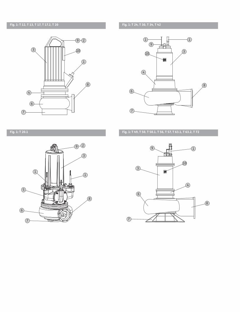
3.2. SetupWilo-EMU FA pumps with T motor are submersible sewage pumps that can be operated vertically in stationary wet well installation and, depending on themotorsize,inportablewetwellandstationarydry well installation.Differentdesignsresultfromtheconfigurableop-tions for installation type, hydraulics, and motor.
Fig. 1.: Description of units
1 Cable 6 Hydraulics housing
2 Handle 7 Suction connection
3 Motor housing 8 Pressure connection
4 Seal housing with sealing chamber 9 Attachment point for
chains with shackle5 Bearing housing 10 Rating plate
3.2.1. HydraulicsRotodynamichydraulicswithhorizontalpressureconnectionandflangeconnection.Variousimpellershapes are used as the impeller:
• Z = Two-channel• D = Three-channel• V=Four-channel
• SOLID impellers• T = Closed SOLID impeller
• G = Semi-open SOLID impellerThefollowingcomponentsarealsofitted,depend-ing on type:
• Inspection cover Opening on hydraulics housing for clearing block-ages in the hydraulics.
• Impeller wear ring Theimpellerwearringcanbefittedtochannelim-pellers and determines the gap between the suction area and the impeller. The larger the gap, the lower the output, and the greater the risk of clogging.
• Neck ring Theneckringisfittedinthesuctionareaofthehydraulics and determines the gap between the suction area and the impeller. The larger the gap, the lower the output, and the greater the risk of clogging.The neck ring and impeller wear ring are subject to increased wear, which means they can be replaced toensurelongandefficientoperationofthehy-draulics.The pump is not self-priming, in other words, the fluid must flow in either automatically or with supply pressure.
3.2.2. MotorSingle or three phase AC dry motors are used as the motors.Themotoriscooledbythefluidaroundit.Thewasteheatistransferreddirectlytothefluidviathemotorhousing.Forsizesupto49andalsoforsize56,therollerbearingsarepermanentlylubri-catedandthereforemaintenance-free.Forsize50,thelowerbearingrequiresregreasing.Forsize72,the upper and lower bearings require regreasing.If the motor is immersed up to the top edge of the motorhousing,itcanbeusedin“S1”continuousduty. If the motor is not immersed, it may be able tobeusedincontinuousdutyorin“S2”short-timeduty,dependingonitssizeandpowerclass.The operating mode for non-immersed operation must also be observed in the case of dry well instal-lation.For exact specifications about the operating mode, refer to the rating plate or the enclosed data sheet.
In the case of motors with high power, the waste heat generated can cause water to condense in the motor.Motorsofsize24andhigherarethereforeequipped with a separate leakage chamber for the condensation water. The condensation water can be drained when the motor compartment monitoring is tripped.
Installation and operating instructions Wilo-EMU FA+T-Motor 21
PRODUCT DESCRIPTION US English
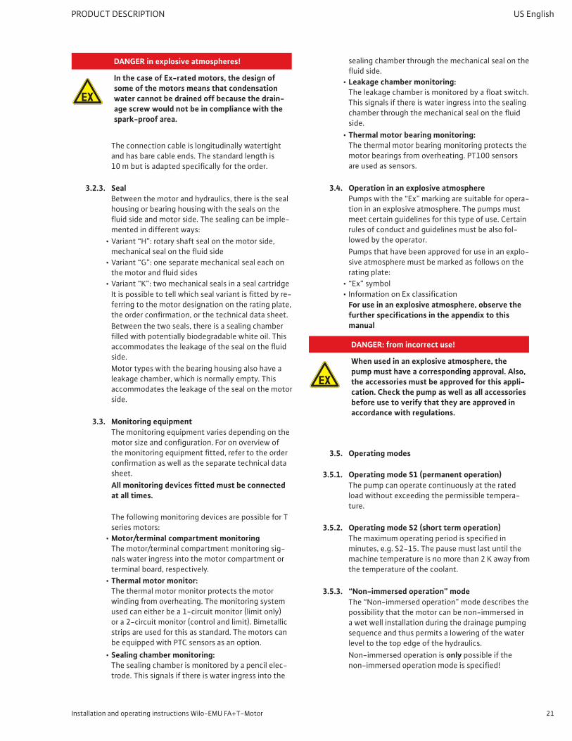
DANGER in explosive atmospheres!
In the case of Ex-rated motors, the design of some of the motors means that condensation water cannot be drained off because the drain-age screw would not be in compliance with the spark-proof area.
The connection cable is longitudinally watertight and has bare cable ends. The standard length is 10 mbutisadaptedspecificallyfortheorder.
3.2.3. SealBetween the motor and hydraulics, there is the seal housing or bearing housing with the seals on the fluidsideandmotorside.Thesealingcanbeimple-mented in different ways:
• Variant“K”:twomechanicalsealsinasealcartridgeItispossibletotellwhichsealvariantisfittedbyre-ferring to the motor designation on the rating plate, theorderconfirmation,orthetechnicaldatasheet.Between the two seals, there is a sealing chamber filledwithpotentiallybiodegradablewhiteoil.Thisaccommodatestheleakageofthesealonthefluidside.Motor types with the bearing housing also have a leakage chamber, which is normally empty. This accommodates the leakage of the seal on the motor side.
3.3. Monitoring equipmentThe monitoring equipment varies depending on the motorsizeandconfiguration.Foronoverviewofthemonitoringequipmentfitted,refertotheorderconfirmationaswellastheseparatetechnicaldatasheet.All monitoring devices fitted must be connected at all times.
The following monitoring devices are possible for T series motors:
• Motor/terminal compartment monitoring The motor/terminal compartment monitoring sig-nals water ingress into the motor compartment or terminal board, respectively.
• Thermal motor monitor: The thermal motor monitor protects the motor winding from overheating. The monitoring system used can either be a 1-circuit monitor (limit only) or a 2-circuit monitor (control and limit). Bimetallic strips are used for this as standard. The motors can be equipped with PTC sensors as an option.
• Sealing chamber monitoring: The sealing chamber is monitored by a pencil elec-trode. This signals if there is water ingress into the
sealing chamber through the mechanical seal on the fluidside.
• Leakage chamber monitoring: Theleakagechamberismonitoredbyafloatswitch.This signals if there is water ingress into the sealing chamberthroughthemechanicalsealonthefluidside.
• Thermal motor bearing monitoring: The thermal motor bearing monitoring protects the motor bearings from overheating. PT100 sensors are used as sensors.
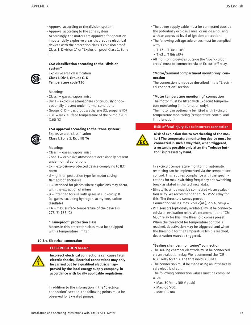
3.4. Operation in an explosive atmospherePumpswiththe“Ex”markingaresuitableforopera-tion in an explosive atmosphere. The pumps must meet certain guidelines for this type of use. Certain rules of conduct and guidelines must be also fol-lowed by the operator.Pumps that have been approved for use in an explo-sive atmosphere must be marked as follows on the rating plate:
• “Ex”symbol• InformationonExclassification
For use in an explosive atmosphere, observe the further specifications in the appendix to this manual
DANGER: from incorrect use!
When used in an explosive atmosphere, the pump must have a corresponding approval. Also, the accessories must be approved for this appli-cation. Check the pump as well as all accessories before use to verify that they are approved in accordance with regulations.
3.5. Operating modes
3.5.1. Operating mode S1 (permanent operation)The pump can operate continuously at the rated load without exceeding the permissible tempera-ture.
3.5.2. Operating mode S2 (short term operation)Themaximumoperatingperiodisspecifiedinminutes, e.g. S2-15. The pause must last until the machinetemperatureisnomorethan2 Kawayfromthe temperature of the coolant.
3.5.3. “Non-immersed operation” modeThe“Non-immersedoperation”modedescribesthepossibility that the motor can be non-immersed in a wet well installation during the drainage pumping sequence and thus permits a lowering of the water level to the top edge of the hydraulics.Non-immersed operation is only possible if the non-immersedoperationmodeisspecified!
22 WILO SE 2015-07 v05 Letter
US English TRANSPORT AND STORAGE
If no operating mode is specified for non-im-mersed operation, non-immersed operation is not permitted!
Duringnon-immersedoperation,themaximumfluidtemperature and ambient temperature must not be exceeded. The maximum ambient temperature is equivalenttothemaximumfluidtemperature.
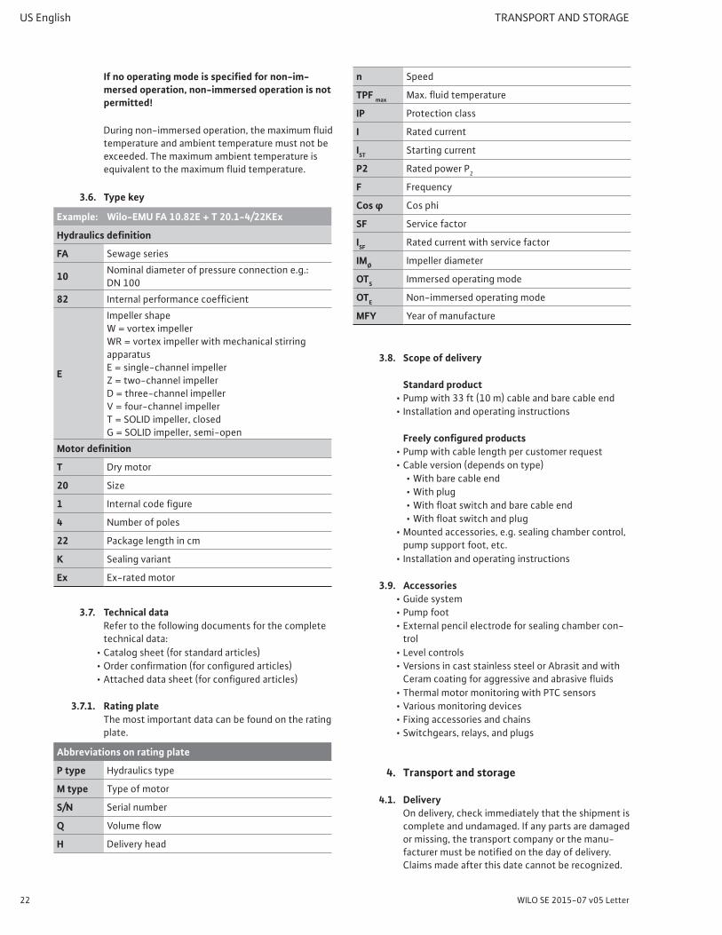
3.6. Type key
Example: Wilo-EMU FA 10.82E + T 20.1-4/22KEx
Hydraulics definition
FA Sewage series
10 Nominal diameter of pressure connection e.g.: DN 100
• Thermal motor monitoring with PTC sensors• Variousmonitoringdevices• Fixing accessories and chains• Switchgears, relays, and plugs
4. Transport and storage
4.1. DeliveryOn delivery, check immediately that the shipment is complete and undamaged. If any parts are damaged or missing, the transport company or the manu-facturermustbenotifiedonthedayofdelivery.Claimsmadeafterthisdatecannotberecognized.
Installation and operating instructions Wilo-EMU FA+T-Motor 23
INSTALLATION US English
Any damage to parts must be noted on the freight documentation.
4.2. TransportOnly the appropriate and approved fastening de-vices and transportation and lifting equipment may beused.Thesemusthavesufficientloadbearingcapacity to ensure that the pump can be transport-ed safely. If chains are used they must be secured against slipping.Thepersonnelmustbequalifiedforthetasksandmust follow all applicable national safety regula-tions during the work.The pumps are delivered by the manufacturer or shipping agency in suitable packaging. This nor-mally precludes the possibility of damage occurring during transport and storage. The packaging should be stored in a safe place for reuse if the product is frequently used at different locations.
4.3. StorageNewly supplied pumps are prepared so that they can be stored for at least 1 year. The pump should be cleaned thoroughly before it is put into temporary storage.The following should be taken into consideration for storage:
• Placethepumponafirmsurfaceandsecureitagainst slipping and falling over. Submersible sew-age pumps are stored vertically.
DANGER: from falling
Never set the pump down unsecured. If the pump falls over, it could cause an injury.
• The pumps can be stored at temperatures down to +5 °F(-15 °C).Thestorageareamustbedry.Werecommend a frost-protected room for storage withatemperaturebetween41 °F(5 °C)and77 °F(25 °C).
• Suction and pressure connections must be sealed securely to prevent the entry of contamination.
• All power supply cables must be protected against kinking, damage, and moisture ingress.
DANGER: electrical hazard!
Damaged power supply cables can cause fatal injury! Defective cables must be replaced by a qualified electrician immediately.
CAUTION: beware of moisture!
Moisture penetrating the cable will damage both the pump and the cable. Never immerse the cable end in fluid and always protect it from moisture.
• The pump must be protected from direct sunlight, heat, dust, and frost.
• The impellers should be checked at regular intervals. This prevents jamming of the bearings and it renews thefilmoflubricationonthemechanicalseal.
WARNING: sharp edges!
Sharp edges can form on the impellers and hydraulic openings. There is a risk of injury! Wear the necessary protective clothing, such as protective gloves.
• If the pump has been stored for a long period of time, it should be cleaned of contaminants such as dust and oil residue before commissioning. Check that the impellers move freely and check the hous-ing coatings for damage.Prior to commissioning, the fill level in the seal-ing chamber should be checked and topped up, if necessary. Damaged coatings must be repaired immedi-ately. Only an intact coating fulfills its intended purpose.
Please note that elastomer parts and coatings be-come brittle over time. If the product is to be stored for longer than 6 months, we recommend checking these parts and replacing them as necessary. Con-sult the manufacturer for details.
4.4. Return deliveryPumps that are returned to the factory must be properly packaged. This means that impurities have been removed from the pump and that it has been decontaminatedifusedwithfluidsthatarehazard-ous to health.For shipping, the parts must be packed in tear-proof plasticbagsofsufficientsizeinsuchamannerthatthey are tightly sealed and leak proof. Furthermore, the packaging must protect the pump from damage during transportation. If you have any questions, please contact the manufacturer.
5. InstallationIn order to prevent damage to the product or serious injury during installation, the following points must be observed:
• Installation work – assembly and installation of thepump–mayonlybecarriedoutbyqualifiedpersons. The safety instructions must be followed at all times.
• The pump must be inspected for transport damage before any installation work is carried out.
5.1. GeneralFor planning and operation of sewage systems, ob-serve the applicable local regulations and directives
24 WILO SE 2015-07 v05 Letter
US English INSTALLATION
for sewage technology (such as those of the Ger-man Association for Water, Wastewater and Waste).Note that pressure surges can occur, in particular with stationary installations where water is pumped with relatively long discharge pipes (especially with steady ascents or steep terrain). This can result in the destruction of the pump/system.If you are using level control, make sure that the minimum water coverage is present. Air pockets in the hydraulic housing or piping system must be avoided at all costs and must be removed using a suitable ventilation system. Protect the pump from frost.
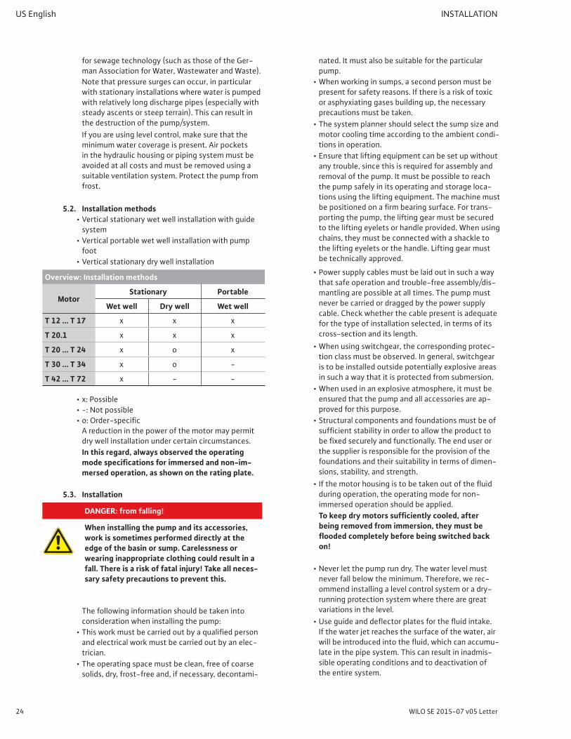
A reduction in the power of the motor may permit dry well installation under certain circumstances.In this regard, always observed the operating mode specifications for immersed and non-im-mersed operation, as shown on the rating plate.
5.3. Installation
DANGER: from falling!
When installing the pump and its accessories, work is sometimes performed directly at the edge of the basin or sump. Carelessness or wearing inappropriate clothing could result in a fall. There is a risk of fatal injury! Take all neces-sary safety precautions to prevent this.
The following information should be taken into consideration when installing the pump:
• Thisworkmustbecarriedoutbyaqualifiedpersonand electrical work must be carried out by an elec-trician.
• The operating space must be clean, free of coarse solids, dry, frost-free and, if necessary, decontami-
nated. It must also be suitable for the particular pump.
• When working in sumps, a second person must be present for safety reasons. If there is a risk of toxic or asphyxiating gases building up, the necessary precautions must be taken.
• Thesystemplannershouldselectthesumpsizeandmotor cooling time according to the ambient condi-tions in operation.
• Ensure that lifting equipment can be set up without any trouble, since this is required for assembly and removal of the pump. It must be possible to reach the pump safely in its operating and storage loca-tions using the lifting equipment. The machine must bepositionedonafirmbearingsurface.Fortrans-porting the pump, the lifting gear must be secured to the lifting eyelets or handle provided. When using chains, they must be connected with a shackle to the lifting eyelets or the handle. Lifting gear must be technically approved.
• Power supply cables must be laid out in such a way that safe operation and trouble-free assembly/dis-mantling are possible at all times. The pump must never be carried or dragged by the power supply cable. Check whether the cable present is adequate for the type of installation selected, in terms of its cross-section and its length.
• When using switchgear, the corresponding protec-tion class must be observed. In general, switchgear is to be installed outside potentially explosive areas in such a way that it is protected from submersion.
• When used in an explosive atmosphere, it must be ensured that the pump and all accessories are ap-proved for this purpose.
• Structural components and foundations must be of sufficientstabilityinordertoallowtheproducttobefixedsecurelyandfunctionally.Theenduserorthe supplier is responsible for the provision of the foundations and their suitability in terms of dimen-sions, stability, and strength.
• Ifthemotorhousingistobetakenoutofthefluidduring operation, the operating mode for non-immersed operation should be applied.To keep dry motors sufficiently cooled, after being removed from immersion, they must be flooded completely before being switched back on!
• Never let the pump run dry. The water level must never fall below the minimum. Therefore, we rec-ommend installing a level control system or a dry-running protection system where there are great variations in the level.
• Useguideanddeflectorplatesforthefluidintake.If the water jet reaches the surface of the water, air willbeintroducedintothefluid,whichcanaccumu-late in the pipe system. This can result in inadmis-sible operating conditions and to deactivation of the entire system.
Installation and operating instructions Wilo-EMU FA+T-Motor 25
INSTALLATION US English
• Check that the available planning documentation (installation plans, layout of the operating space, intake ratios) is complete and correct.
• Also observe all regulations, rules, and legal require-ments for working with and underneath heavy sus-pended loads. Wear appropriate protective clothing/equipment.
• Please also observe the applicable national accident prevention regulations and trade association safety provisions.
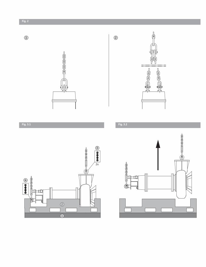
5.3.1. Attaching lifting gear to the pump
Fig. 2.: Attaching lifting gear correctly
1 Pump with one attachment point
2 Pump with two attachment points
Note the following points when attaching the lifting gear:
• Onlyuseauthorizedliftinggear.• The lifting gear must have a corresponding bearing
capacity.• Use 1 or 2-line lifting gear depending on the at-
tachment points on the pump.• The lifting gear must be attached to the pump using
shackles.• Observe the installation and operating instructions
for the lifting gear with regard to permitted use.
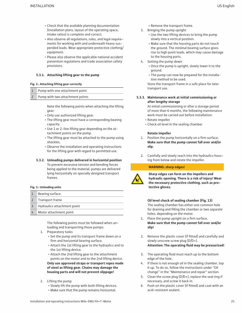
5.3.2. Unloading pumps delivered in horizontal positionTo prevent excessive tension and bending forces being applied to the material, pumps are delivered lyinghorizontallyonspeciallydesignedtransportframes.
Fig. 3.: Unloading units
1 Bearing surface
2 Transport frame
3 Hydraulics attachment point
4 Motor attachment point
The following points must be followed when un-loading and transporting these pumps:
1. Preparatory tasks• Set the pump and its transport frame down on a firmandhorizontalbearingsurface.
• Attach the 1st lifting gear to the hydraulics and to the 1st lifting device.
• Attach the 2nd lifting gear to the attachment points on the motor and to the 2nd lifting device.
Only use approved straps or transport ropes made of steel as lifting gear. Chains may damage the housing parts and will not prevent slippage!
2. Lifting the pump• Slowly lift the pump with both lifting devices.• Makesurethatthepumpremainshorizontal.
• Remove the transport frame.3. Bringing the pump upright
• Use the two lifting devices to bring the pump slowly into a vertical position.
• Make sure that the housing parts do not touch the ground. The minimal bearing surface gives rise to high point loads, which may cause damage to the housing parts.
4. Setting the pump down• Once the pump is upright, slowly lower it to the
ground.• The pump can now be prepared for the installa-
tion method to be used.Store the transport frame in a safe place for later transport use.
5.3.3. Maintenance work at initial commissioning or after lengthy storageAt initial commissioning or after a storage period of more than 6 months, the following maintenance work must be carried out before installation:
• Rotate impeller• Check oil level in the sealing chamber
Make sure that the pump cannot fall over and/or slip.
2. Carefully and slowly reach into the hydraulics hous-ing from below and rotate the impeller.
WARNING: sharp edges!
Sharp edges can form on the impellers and hydraulic opening. There is a risk of injury! Wear the necessary protective clothing, such as pro-tective gloves.
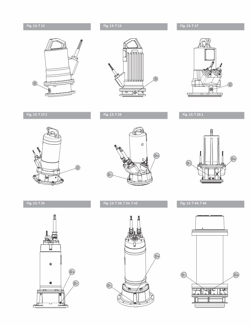
Oil level check of sealing chamber (Fig. 13)The sealing chamber has either one common hole fordrainingandfillingthechamberortwoseparateholes, depending on the motor.
1. Placethepumpuprightonafirmsurface.Make sure that the pump cannot fall over and/or slip!
2. Removetheplasticcover(iffitted)andcarefullyandslowly unscrew screw plug (D/D+).Attention: The operating fluid may be pressurized!
3. Theoperatingfluidmustreachuptothebottomedge of the hole.
4. If there is not enough oil in the sealing chamber, top itup.Todoso,followtheinstructionsunder“Oilchange”inthe“Maintenanceandrepair”section.
5. Clean the screw plug (D/D+), replace the seal ring if necessary, and screw it back in.
5.3.4. Stationary wet well installationA guide system must be installed for wet well instal-lation. This must be ordered separately. The pipe system on the pressure side is connected to this.The connected pipe system must be self-sup-porting, i.e. it must not be supported by the guide system.
The operating space must be laid out so that the guide system can be installed and operated without difficulty.If the motor emerges from immersion during opera-tion,thefollowingspecificationsmustbestrictlyobserved:
• Maximum ambient temperature• Maximumfluidtemperature• Specificationsfor“non-immersedoperatingmode”
The ambient temperature is equivalent to the fluid temperature. For the maximum fluid tem-perature, refer to the rating plate or the separate data sheet.
Fig. 4.: Stationary wet well installation
1 Guide system 6 Lifting gear
2 Non-return valve 7a Min. water level for im-mersed operation
3 Gate valve 7b Min. water level for non-immersed operation*
4 Pipe elbow 8 Impact protection plate
5Guide pipe (to be provided by the customer)
9 Inlet
A Minimum distances in parallel operation
B Minimum distances in alternating operation
* The operating mode for non-immersed operation depends on the motor. See the rating plate and the enclosed data sheet.
Work steps1. Installationoftheguidesystem:about1-2 h
(see the installation and operating instructions for the guide system).
2. Preparing the pump for operation on a guide sys-tem:about<1 h (please see the operating manual for the guide system).
functions properly.• Secure the lifting equipment to the pump with
the shackle, lift the pump, and then lower slowly onto the guide pipes in the operating space.
• Hold the power supply cables slightly taut when lowering.
• When the pump is connected to the guide system, ensure that the power supply cables are
secured adequately to prevent them falling down and or being damaged.
• Have the electrical connections made by a quali-fiedelectrician.
• The pressure connection is sealed by its own weight.
4. Install optional accessories, such as dry-running protection or level controls.
5. Startingupthepump:about1 h• Asdescribedinthe“Commissioning”section• For new installation: Flood the operating space• Ventthepressurepipe.
5.3.5. Portable wet well installationIn this installation type, the pump has to be equipped with a pump foot (available as an option). This is attached to the suction port and ensures the minimum ground clearance and a secure footing if placed on a solid bearing surface. In this ver-sion, the pump can be positioned anywhere in the operating space. If used in an operating space with a soft bearing surface, a hard base must be used to prevent sinking. A pressure hose is connected on the pressure side.If operated for longer periods of time in this instal-lationtype,thepumpmustbefastenedtothefloor.This prevents vibration and ensures quiet and low-wearing running.If the motor emerges from immersion during opera-tion,thefollowingspecificationsmustbestrictlyobserved:
• Maximum ambient temperature• Maximumfluidtemperature• Specificationsfor“non-immersedoperatingmode”
The ambient temperature is equivalent to the fluid temperature. For the maximum fluid tem-perature, refer to the rating plate or the separate data sheet.
CAUTION: beware of burns!
The housing parts can heat up to well above 104 °F (40 °C). There is a risk of burns! After switching it off, let the pump cool down to am-bient temperature.
Fig. 5.: Portable wet well installation
1 Lifting gear 5 Storzhosecoupling
2 Pump foot 6 Pressure hose
3Pipe elbow for hose connectionorStorzpipecoupling
7a Min. water level for im-mersed operation
4 Storzpipecoupling 7b Min. water level for non-immersed operation*
* The operating mode for non-immersed operation depends on the motor. See the rating plate and the enclosed data sheet.
Installation and operating instructions Wilo-EMU FA+T-Motor 27
INSTALLATION US English
Work steps1. Preparingpumps:about1 h
• Install the pump foot on the suction connection.• Install the pipe elbow on the pressure connection.• Fasten the pressure hose to the pipe elbow with
a hose clip. Alternatively,aStorzpipecouplingcanbeinstalledonthepipeelbowandaStorzhosecou-pling can be installed on the pressure hose.
2. Installingthepump:about1-2 h• Position pump in installation location. If neces-
sary, secure lifting equipment to the pump with a shackle, lift the pump, and then lower to the intended location (sump, pit).
• Check that the pump is vertical and on a solid bearing surface. Avoid sinking.
• Route the power supply cable so it cannot be damaged.
• Have the electrical connections made by a quali-fiedelectrician.
• Route the pressure hose so that it is not damaged andfastenitatcertainpoints(e.g.outflow).
DANGER: risk of pressure hose becoming sepa-rated!
Uncontrolled separation or movement of the pressure hose can result in injuries. Secure the pressure hose appropriately. Prevent buckling of the pressure hose.
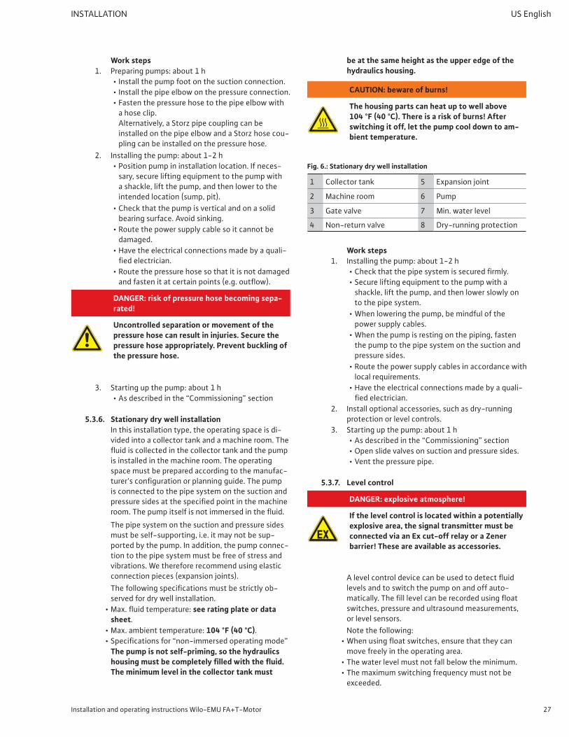
5.3.6. Stationary dry well installationIn this installation type, the operating space is di-vided into a collector tank and a machine room. The fluidiscollectedinthecollectortankandthepumpis installed in the machine room. The operating space must be prepared according to the manufac-turer'sconfigurationorplanningguide.Thepumpis connected to the pipe system on the suction and pressuresidesatthespecifiedpointinthemachineroom.Thepumpitselfisnotimmersedinthefluid.The pipe system on the suction and pressure sides must be self-supporting, i.e. it may not be sup-ported by the pump. In addition, the pump connec-tion to the pipe system must be free of stress and vibrations. We therefore recommend using elastic connection pieces (expansion joints).Thefollowingspecificationsmustbestrictlyob-served for dry well installation.
• Max.fluidtemperature:see rating plate or data sheet.
The pump is not self-priming, so the hydraulics housing must be completely filled with the fluid. The minimum level in the collector tank must
be at the same height as the upper edge of the hydraulics housing.
CAUTION: beware of burns!
The housing parts can heat up to well above 104 °F (40 °C). There is a risk of burns! After switching it off, let the pump cool down to am-bient temperature.
Fig. 6.: Stationary dry well installation
1 Collector tank 5 Expansion joint
2 Machine room 6 Pump
3 Gate valve 7 Min. water level
4 Non-return valve 8 Dry-running protection
Work steps1. Installingthepump:about1-2 h
• Checkthatthepipesystemissecuredfirmly.• Secure lifting equipment to the pump with a
shackle, lift the pump, and then lower slowly on to the pipe system.
• When lowering the pump, be mindful of the power supply cables.
• When the pump is resting on the piping, fasten the pump to the pipe system on the suction and pressure sides.
• Route the power supply cables in accordance with local requirements.
• Have the electrical connections made by a quali-fiedelectrician.
2. Install optional accessories, such as dry-running protection or level controls.
3. Startingupthepump:about1 h• Asdescribedinthe“Commissioning”section• Open slide valves on suction and pressure sides.• Ventthepressurepipe.
5.3.7. Level control
DANGER: explosive atmosphere!
If the level control is located within a potentially explosive area, the signal transmitter must be connected via an Ex cut-off relay or a Zener barrier! These are available as accessories.
Alevelcontroldevicecanbeusedtodetectfluidlevels and to switch the pump on and off auto-matically.Thefilllevelcanberecordedusingfloatswitches, pressure and ultrasound measurements, or level sensors.Note the following:
• Whenusingfloatswitches,ensurethattheycanmove freely in the operating area.
• The water level must not fall below the minimum.• The maximum switching frequency must not be
exceeded.
28 WILO SE 2015-07 v05 Letter
US English INSTALLATION
• Ifthefluidlevelsfluctuatestrongly,thenlevelcontrol should be implemented using two measur-ing points as standard. This allows larger intervals before control is triggered.
InstallationFor correct installation, please see the installation and operation instructions for the level control device.Observe the information on the maximum switch-ing frequency and the minimum water level!
5.4. Dry-running protectionMake sure that no air enters the hydraulics housing. The pump must therefore always be immersed in thefluiduptothetopedgeofthehydraulichous-ing. For optimum operational reliability, we recom-mend installing a dry-running protection system.Correctrunningisensuredbyfloatswitchesorlevelsensors.Thefloatswitchorsensorisfixedinthesump and switches off the pump when the water level falls below the minimum coverage level. If dry-running protection is only put into effect with one floaterwhenfilllevelsdeviatesignificantly,thenthe pump may turn on and off constantly! This can result in the maximum number of motor activations (switching cycles) being exceeded.
5.4.1. Remedies for avoiding excessive switching cycles• Manual reset
The motor is switched off when the water level falls below the minimum coverage level and switched backonwhenasufficientwaterlevelisreached.
• Separate reactivation point Asecondswitchingpoint(additionalfloaterorelectrode)isusedtoobtainasufficientdifferencebetween the activation and deactivation points. This prevents constant switching. This function can be implemented using a level control relay.
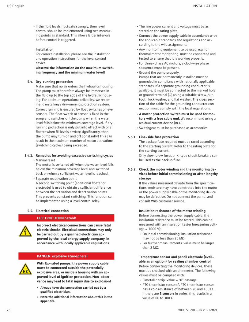
5.5. Electrical connection
ELECTROCUTION hazard!
Incorrect electrical connections can cause fatal electric shocks. Electrical connections may only be carried out by a qualified electrician ap-proved by the local energy supply company, in accordance with locally applicable regulations.
DANGER: explosive atmosphere!
With Ex-rated pumps, the power supply cable must be connected outside the potentially explosive area, or inside a housing with an ap-proved level of ignition protection. Non-obser-vance may lead to fatal injury due to explosion!
• Always have the connection carried out by a qualified electrician.
• Note the additional information about this in the appendix.
• The line power current and voltage must be as stated on the rating plate.
• Connect the power supply cable in accordance with the applicable standards and regulations and ac-cording to the wire assignment.
• Any monitoring equipment to be used, e.g. for thermal motor monitoring, must be connected and tested to ensure that it is working properly.
• For three-phase AC motors, a clockwise phase sequence must be present.
• Ground the pump properly. Pumps that are permanently installed must be grounded in compliance with nationally applicable standards. If a separate grounding conductor is available, it must be connected to the marked hole or ground terminal (;) using a suitable screw, nut, toothlockwasher,andflatwasher.Thecrosssec-tion of the cable for the grounding conductor con-nection must comply with the local regulations.
• A motor protection switch must be used for mo-tors with a free cable end. We recommend using a residual current device (RCD).
• Switchgear must be purchased as accessories.
5.5.1. Line-side fuse protectionThe backup fuse required must be rated according to the starting current. Refer to the rating plate for the starting current.Only slow-blow fuses or K-type circuit breakers can be used as the backup fuse.
5.5.2. Check the motor winding and the monitoring de-vices before initial commissioning or after lengthy storageIfthevaluesmeasureddeviatefromthespecifica-tions, moisture may have penetrated into the motor or the power supply cable or the monitoring device may be defective. Do not connect the pump, and consult Wilo customer service.
Insulation resistance of the motor windingBefore connecting the power supply cable, the insulation resistance must be tested. This can be measured with an insulation tester (measuring volt-age=1000 V):• On initial commissioning: insulation resistance maynotbelessthan20 MΩ.
• For further measurements: value must be larger than2 MΩ.
Temperature sensor and pencil electrode (avail-able as an option) for sealing chamber controlBefore connecting the monitoring devices, these must be checked with an ohmmeter. The following values must be complied with:• Bimetallicstrip:Value=“0”passage• PTC thermistor sensor: A PTC thermistor sensor hasacoldresistanceofbetween20and100 Ω. If there are 3 sensors in series, this results in a valueof60to300 Ω.
Installation and operating instructions Wilo-EMU FA+T-Motor 29
INSTALLATION US English
If there are 4 sensors in series, this results in a value of80to400 Ω.• Pt100 sensor: Pt100 sensors have a value of 100 Ωat32 °F(0 °C).Between32 °F(0 °C)and212 °F(100 °C),thisvalueincreasesby0.214 Ωevery1 °F(0.385 Ωevery1 °C).Atanambienttemperatureof68 °F(20 °C),theyreachavalueof107.7 Ω.
• Pencilelectrode:Thisvaluemustapproachinfin-ity. If the value is low, there is water in the oil. Also observe the instructions of the optional evalua-tion relay.
5.5.3. Three phase AC motorThe three phase version is supplied with bare cable ends. The connection to line power is made in the switchgear.The following list of various connection diagrams only covers the cable assignments available as standard.Fororder-specificversions,aseparateconnection diagram is provided for each order.Please note that the individual wires are labeled according to the connection. Do not cut them off! Otherwise, it will no longer be possible to allocate the wires to the connections!
Electrical connections may only be made by a qualified electrician!
Fig. 7.: Motor connection diagram in direct starting
U
Line powerDK Leakage detection for
motor compartmentV
W PE Ground
Fig. 8.: Motor connection diagram in star-delta starting
U1Linepower;startofwinding
U2Linepower;endofwind-ingV1 V2
W1 W2
PE Ground DK Leakage detection for motor compartment
5.5.4. Connecting the monitoring devicesThe following list of various connection diagrams only covers the cable assignments available as standard.Fororder-specificversions,aseparateconnection diagram is provided for each order.All monitoring devices must be connected at all times.
RISK of fatal injury due to explosive atmo-sphere!
If the monitoring devices are not connected correctly, there is a risk of fatal injury due to explosion if used in potentially explosive areas! Always have the connection carried out by an electrician. If the pump is used in potentially explosive areas:
• The temperature monitor must be connected via an evaluation relay. We recommend the “CM-MSS” relay for this. The threshold comes preset.
• Deactivation by the temperature limiter must be conducted with an anti-reactivation mechanism, meaning that reactivation should only be pos-sible if the “release button” has been pressed manually!
• The electrode for sealing chamber control must be connected via an intrinsically safe circuit with an evaluation relay. We recommend the “XR-41x” relay for this. The threshold is 30 kΩ.
• Also note the additional information in the ap-pendix!
Motor/terminal compartment monitoring• The motor/terminal compartment monitoring
(moisture sensor) must be connected via an evalua-tionrelay.Werecommendthe“NIV 101/A”relayforthis.Thethresholdis30 kΩ. When the threshold is reached, the unit must switch off.
Motor temperature monitoring• Bimetallic strips must be connected in the switch-
gear itself or via an evaluation relay. Connectionvalues:max.250 V(AC),2.5 A,cosφ= 1
• PTC sensors must be connected via an evaluation relay.Werecommendthe“CM-MSS”relayforthis.The threshold comes preset.
• Depending on whether there are 1 or 2-temperature circuits, the following triggering status must occur when the threshold value is reached:• Temperature limiting (1-temperature circuit):
When the threshold is reached, the unit must switch off.
• Temperature control and limiting (2-temperature circuits): When the threshold for the low temper-ature(control)isreached,an“earlywarning”may be triggered, and when the threshold for the high temperature(limiting)isreached,a“deactivation”must be triggered.
Comply with the information in the appendix re-garding use in potentially explosive atmospheres!
For this reason, no warranty claims can be accepted for any damage to the winding resulting from un-suitable motor monitoring.
30 WILO SE 2015-07 v05 Letter
US English INSTALLATION
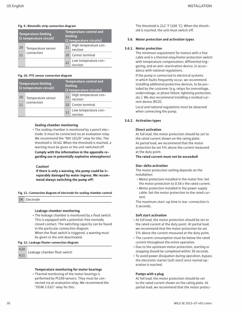
Fig. 9.: Bimetallic strip connection diagram
Temperature limiting(1 temperature circuit)
Temperature control and limiting(2 temperature circuits)
20 Temperature sensor connection
21 High temperature con-nection
21 20 Center terminal
22 Low temperature con-nection
Fig. 10.: PTC sensor connection diagram
Temperature limiting(1 temperature circuit)
Temperature control and limiting(2 temperature circuits)
10 Temperature sensor connection
11 High temperature con-nection
11 10 Center terminal
12 Low temperature con-nection
Sealing chamber monitoring• The sealing chamber is monitored by a pencil elec-
trode. It must be connected via an evaluation relay. Werecommendthe“NIV 101/A”relayforthis.Thethresholdis30 kΩ.Whenthethresholdisreached,awarning must be given or the unit switched off.Comply with the information in the appendix re-garding use in potentially explosive atmospheres!
Caution! If there is only a warning, the pump could be ir-reparably damaged by water ingress. We recom-mend always switching the pump off!
Fig. 11.: Connection diagram of electrode for sealing chamber control
This is equipped with a potential-free normally closed contact. The switching capacity can be found in the particular connection diagram. Whenthefloatswitchistriggered,awarningmustbe given or the unit deactivated.
Fig. 12.: Leakage floater connection diagram
K20Leakagechamberfloatswitch
K21
Temperature monitoring for motor bearings• Thermal monitoring of the motor bearings is
performed by Pt100 sensors. They must be con-nected via an evaluation relay. We recommend the “DGW 2.01G”relayforthis.
Thethresholdis212 °F(100 °C).Whenthethresh-old is reached, the unit must switch off.
5.6. Motor protection and activation types
5.6.1. Motor protectionThe minimum requirement for motors with a free cable end is a thermal relay/motor protection switch with temperature compensation, differential trig-gering, and an anti-reactivation device, in accor-dance with national regulations.If the pump is connected to electrical systems in which faults frequently occur, we recommend installing additional protective devices, to be pro-vided by the customer (e.g. relays for overvoltage, undervoltage,orphasefailure;lightningprotection,etc.). We also recommend installing a residual cur-rent device (RCD).Local and national regulations must be observed when connecting the pump.
5.6.2. Activation types
Direct activationAt full load, the motor protection should be set to the rated current shown on the rating plate.At partial load, we recommend that the motor protection be set 5% above the current measured at the duty point.The rated current must not be exceeded!
Star-delta activationThe motor protection setting depends on the installation:• Motor protection installed in the motor line: Set themotorprotectionto0.58 x theratedcurrent.
• Motor protection installed in the power supply cable: Set the motor protection to the rated cur-rent.
The maximum start-up time in star-connection is 3 seconds.
Soft start activation• At full load, the motor protection should be set to
the rated current at the duty point. At partial load, we recommend that the motor protection be set 5% above the current measured at the duty point.
• The current consumption must be below the rated current throughout the entire operation.
• Due to the upstream motor protection, starting or stopping should be completed within 30 seconds.
• To avoid power dissipation during operation, bypass the electronic starter (soft start) once normal op-eration is reached.
Pumps with a plugAt full load, the motor protection should be set to the rated current shown on the rating plate. At partial load, we recommend that the motor protec-
Installation and operating instructions Wilo-EMU FA+T-Motor 31
COMMISSIONING US English
tion be set 5% above the current measured at the duty point.Plugs are not immersion-proof. Note the protec-tion class (IP). The socket must be installed where it will not be submersed.
5.6.3. Operation with frequency convertersOperation on a frequency converter is possible. Note the information about this in the appendix.
6. CommissioningThe“Commissioning”sectioncontainsalltheim-portant instructions for the operating personnel for starting up and operating the pump.The following conditions must be adhered to and monitored:
• Type of installation• Operating mode• Minimum water submersion/max. immersion depth
These general conditions must also be checked after a long period without operation, and any defects detected must be repaired!
Always keep this manual either by the pump or in a place specially reserved for it, where it is accessible for the entire operating personnel at all times.In order to prevent damage or serious injury when commissioning the pump, the following points must be observed:
• Commissioning of the pump may only be carried out byqualifiedandtrainedpersonnelinaccordancewith the safety instructions.
• All persons working on or with the pump must have received, read, and understood this operating and maintenance manual.
• All safety devices and emergency cut-outs must be connected and checked to ensure that they work properly.
• Electrical and mechanical adjustments must be madebyqualifiedpersonnel.
• In general, people should be kept out of the working area of the pump. No persons should be allowed in the working area during startup or operation.
• When working in sumps, a second person must be present. Adequate ventilation must be ensured if there is danger of toxic gases forming.
6.1. Electrical systemConnect the pump and install the power supply cablesasdescribedinthe“Installation”sectionandin accordance with applicable national regulations.The pump must be properly protected and ground-ed.Ensure correct direction of rotation. If the direction of rotation is incorrect, the pump will not perform as specifiedandmaybedamaged.
Ensure all monitoring devices are connected and have been tested.
DANGER: electrical hazard!
Electrical current can cause fatal injuries if not handled correctly! All pumps with free cable ends (i.e. without plugs) must be connected by a qualified electrician.
6.2. Rotation controlThe pump is checked and adjusted in the factory to ensure that the direction of rotation is correct. The connection must be made according to the wiring markings.A test run must be performed under general oper-ating conditions!
6.2.1. Checking the direction of rotationThe direction of rotation must be checked by a local electrician using a phase sequence tester. For the correct direction of rotation, a clockwise phase sequence must be present.The pump is not approved for operation with a counterclockwise phase sequence!
6.2.2. If the direction of rotation is incorrectIf the direction of rotation is incorrect for direct start motors, two phases must be swapped. In the case of motors with star-delta starting, the con-nections of two windings must be swapped, e.g. U1 withV1andU2withV2.
6.3. Level controlThe level control device is to be checked to ensure it is installed properly and the settings of the switch-ing points are to be inspected. For the required information please refer to the installation and operating instructions for the level control device, as well as the planning documentation.
6.4. Operation in potentially explosive areasIf the pump is marked accordingly, it can be used inside potentially explosive areas.
RISK of fatal injury due to explosive atmo-sphere!
Pumps without Ex marking must not be used in potentially explosive areas! There is a risk of fatal injury due to explosion! Check your pump before use to verify that it has the relevant ap-proval:
• Ex symbol• Ex classification, e.g. II 2G Eex d IIB T4• Also note the additional information in the ap-
pendix!
32 WILO SE 2015-07 v05 Letter
US English COMMISSIONING
6.5. CommissioningMinor oil leakage at the mechanical seal on delivery is no cause for concern. However, it must be re-movedpriortosubmersioninthefluid.Keep people out of the pump's working area. No persons should be allowed in the working area during startup or operation.
WARNING: danger of crushing!
In portable installations, the pump can fall over when it is switched on or during operation. Make sure that the pump is positioned on a firm bearing surface and that the pump foot is mounted correctly.
If the pump falls over, it must be switched off be-fore setting it up again.In the version with a plug, note the plug's IP protec-tion class.
6.5.1. Before switching on
RISK of fatal injury due to explosion
If the gate valves on the suction and pressure sides are closed during operation, the fluid in the hydraulics housing is heated up by the pumping movement. This heating creates strong pressure in the hydraulics housing. The pressure can result in the pump exploding. Before switch-ing on the unit, ensure that all the slide valves are open and open any closed slide valves.
Check the following:• Cable guidance – no loops, slightly taut• Checkthetemperatureofthefluidandtheimmer-
sion depth – see technical data• The pump sump is to be cleaned of any coarse
contaminants, especially of solids such as sand/grit, metal and stone
• Clean the pipe system on the pressure side• Open all slide valves on the pressure side• Thefluidmustbepresentatleastuptothesuction
opening of the hydraulics housing.• The pipe system must be vented by suitable venting
devices in the system.• Checktoensureallaccessoriesareproperlyfitted• Check switching level of level control and dry-run-
ning protection systems
6.5.2. Switching on/offThe pump is switched on and off using a separate operating point (on/off switch, switchgear) provided by the customer.During the start-up procedure, the rated current is temporarily exceeded. After the start-up procedure isfinished,thecurrentmustnotexceedtheratedcurrent again.
If the motor does not start up, it must be switched off without delay. Before switching it on again, waitforthespecifiedstartpauseandmakesuretorectify the fault.
6.6. Conduct during operation
RISK of fatal injury due to explosion
If the gate valves on the suction and pressure sides are closed during operation, the fluid in the hydraulics housing is heated up by the pumping movement. This heating creates strong pressure in the hydraulics housing. The pressure can result in the pump exploding. Before switch-ing on the unit, ensure that all the slide valves are open and open any closed slide valves.
WARNING: rotating parts!
The rotating parts can crush and sever limbs. Never reach into the hydraulics or touch the rotating parts when the machine is in operation.
• Before performing maintenance or repairs, switch off the pump, disconnect it from the power supply, and secure it against being switched on again without authorization.
• Allow the rotating parts to come to a standstill!
When operating the pump, always follow the locally applicable laws and regulations for work safety, accident prevention, and handling electrical machinery. To help ensure safe working practice, the responsibilities of employees should be clearly specifiedbytheoperator.Allpersonnelarerespon-sible for ensuring that regulations are observed.The pump is equipped with moving parts. During operation, these parts rotate in order to pump the fluid.Certainsubstancesinthefluidcanresultinvery sharp edges forming on the moving parts.The following must be checked at regular intervals:• Operating voltage (permissible deviation +/-5%
of the rated voltage)• Frequency (permissible deviation +/- 2% of the
rated frequency)• Current consumption (permissible deviation be-
tween phases is a maximum of 5%)• Voltagedifferencebetweentheindividualphases
(max. 1%)• Switching frequency and switching pauses (see
• Minimum water submersion, level control device, dry-running protection
• Smooth running• Gate valves in the inlet and pressure pipes must
be open.
Installation and operating instructions Wilo-EMU FA+T-Motor 33
DECOMMISSIONING/DISPOSAL US English
6.6.1. Operation in the limit rangeIfcircumstancesrequireit,thepumpcanbrieflybeoperated in the limit range. The following param-eters must be strictly observed in this case:• Operating voltage (permissible deviation +/-10%
of the rated voltage)• Frequency (permissible deviation +3 to -5% of
the rated frequency)• Voltagedifferencebetweentheindividualphases
(max. 1%)Expect relatively large deviations from the operat-ing data.Continuous duty in the limit range is not recom-mended because the pump is exposed to high wear and thus there is a greater risk of failure!
7. Decommissioning/disposal• All work must be carried out with the greatest care.• Proper protective clothing is to be worn.• When carrying out work in basins and/or tanks, the
applicable local protection measures must be ob-served in all cases. A second person must be present for safety reasons.
• Only lifting equipment that is in a technically per-fect condition and load carrying equipment that has beenofficiallyapprovedmaybeusedforloweringand raising the pump.
RISK of fatal injury due to malfunctions!
Load carrying and lifting equipment must be in a perfect technical condition. Work may only commence once the lifting equipment has been checked and found to be in perfect working or-der. If it is not checked, fatal injuries may result.
7.1. Temporary decommissioningFor this type of shutdown, the pump remains in-stalled and is not cut off from the electricity supply. In the event of temporary decommissioning the pump must remain completely immersed so that it is protected from frost and ice. Ensure that the temperatureofthefluidandintheoperatingspacedoesnotfallbelow37 °F(+3 °C).This ensures that the pump is always ready for op-eration. For extended downtime, a regular (monthly to quarterly) 5 minute test run should be carried out.
CAUTION!
Only perform test runs under the proper operat-ing and usage conditions. Never run the machine dry! This can result in irreparable damage!
7.2. Decommissioning for maintenance work or stor-ageThe system must be switched off and the pump must be disconnected from the power supply by an electrician and secured against being switched on again without permission. Pumps with plugs must be unplugged (do not pull the cable!). Work on removal, maintenance, and storage can then com-mence.
DANGER: from toxic substances!
Pumps that pump liquids hazardous to health must always be decontaminated before under-taking any other work. Otherwise, there is a risk of fatal injury! Wear the necessary physical protection equipment!
CAUTION: beware of burns!
The housing parts can heat up to well above 104 °F (40 °C). There is a risk of burns! After switching it off, let the pump cool down to am-bient temperature.
7.2.1. Removal
Portable wet well installationPumps in portable wet well installation can be lifted out of the pit once they have been disconnected from the power supply and the pressure pipe has been drained. It may be necessary to detach the hosefirst.Itmaybenecessarytouseasuitablelift-ing device.
Stationary wet well installationPumps in stationary wet well installations with a guide system are raised out of the sump using the appropriate lifting equipment. During lifting, always hold the power supply cable slightly taut to prevent it being damaged.The operating space does not have to be emptied especially for this purpose. The gate valves in the inlet and in the pressure pipe must be closed to preventtheoperatingspaceoverflowingorthedischarge pipe being emptied.
Stationary dry well installationFor pumps in stationary dry well installation, the suction- and pressure-side gate valves have to be closedbeforeremoval.Notethatthefluidinthehy-draulics housing will escape during removal. Suitable collector tanks should be positioned to collect all of theescapingfluid.After undoing the screwed connections on the suction and pressure connections, the pump can be removed using suitable lifting equipment. The op-erating space must be cleaned thoroughly after the pump is removed and any drips must be wiped up.
34 WILO SE 2015-07 v05 Letter
US English MAINTENANCE AND REPAIR
7.3. Return delivery/storageFor shipping, the parts must be packed in tear-proof plasticbagsofsufficientsizeinsuchamannerthatthey are tightly sealed and leak proof.For return delivery and storage please also refer to the “Transport and storage” section!
7.4. Disposal
7.4.1. Operating fluidsOils and lubricants must be collected in suitable vessels and disposed of properly in accordance with local directives.
7.4.2. Protective clothingThe protective clothing worn during cleaning and maintenance work must be disposed of in accor-dance with local directives.
7.4.3. ProductProper disposal of this product avoids damage to the environment and risks to personal health.
• Use the services of public or private waste disposal companies, or consult them for the disposal of the product or parts thereof.
• For more information on proper disposal, please contactyourlocalcouncilorwastedisposalofficeorthe supplier from whom you obtained the product.
8. Maintenance and repair
ELECTROCUTION hazard!
There is a risk of fatal electric shocks when performing work on electrical devices. With all maintenance or repair work, the pump must be disconnected from the power supply and se-cured against being switched on again without permission. Damage to the power supply cable may only be rectified by a qualified electrician.
UNAUTHORIZED work could result in fatal injuries!
Maintenance and repair work that affects the safety of Ex protection must be carried out only by the manufacturer or authorized service workshops. Also note the additional information in the ap-pendix!
• Switch off and remove the pump as described in the “Decommissioning/disposal” chapter.
• After maintenance or repair work, the pump must beinstalledandconnectedasdescribedinthe“In-stallation” section.
• The pump must be switched on as described in the “Commissioning” section.Note the following:
• All maintenance and repair work must be carried outbyWilocustomerservice,authorizedserviceworkshops, or trained specialists, with the greatest of care and in a safe workplace. Proper protective clothing is to be worn.
• This manual must be available to and followed by the maintenance staff. Only maintenance and repair work described in this manual may be carried out.Any other work and/or alterations to the con-struction may only be carried out by Wilo cus-tomer service.
• When carrying out work in basins and/or tanks, the applicable local protection measures must be ob-served in all cases. A second person must be present for safety reasons.
• Only lifting equipment that is in a technically per-fect condition and load carrying equipment that has beenofficiallyapprovedmaybeusedforloweringand raising the pump. Make sure that the pump does not jam during lifting and lowering. If the pump does jam, do not apply lifting forces greater than 1.2 times the pump weight. The maximum permissible bearing capacity should never be ex-ceeded!Make sure that the lifting gear, wire rope, and the lifting equipment's safety devices are in perfect working order. Work may only commence if the lifting equipment has been checked and found to be in perfect working order. If it is not checked, fatal injuries may result.
• Electrical work on the pump and the system must becarriedoutbyaqualifiedelectrician.Blownfusesmust be replaced immediately. They must never be repaired.Onlyfusesforthespecifiedelectriccurrentandofthespecifiedtypemaybeused.
• Pumpsthatcirculatefluidsthatarehazardoustohealthorcomeintocontactwithsuchfluidsmustbe decontaminated. In addition, make sure that nogasesthatarehazardoustohealthformorarepresent.
• Operatingfluids(e.g.oils,lubricants,etc.)shouldbe collected in suitable containers and disposed of properly. Also comply with the information in sec-tion7.4“Disposal”!
• Use only genuine parts from the manufacturer.
8.1. Operating fluids
8.1.1. Overview of white oilThesealingchamberisfilledwithwhiteoilthatispotentially biodegradable.
Installation and operating instructions Wilo-EMU FA+T-Motor 35
MAINTENANCE AND REPAIR US English
When changing the oil, we recommend the follow-ing oil types:
• Aral Autin PL*• ShellONDINA919• Esso MARCOL 52* or 82*• BP WHITEMORE WOM 14*• Texaco Pharmaceutical 30* or 40*Alloiltypesmarkedwith“*”areapprovedforusewith foods in accordance with USDA-H1.
8.1.2. Overview of greaseThe following can be used for lubrication grease:
• Esso Unirex N3
8.2. Maintenance intervalsTo ensure reliable operation, various maintenance tasks must be carried out regularly.Themaintenanceintervalsmustbespecifiedac-cording to the load on the pump. Regardless of the specifiedmaintenanceintervals,thepumporinstal-lation must be checked if strong vibrations occur during operation.When used in sewage lifting units inside buildings or on areas of land, the maintenance intervals and tasks should be in accordance with the require-ments of local directives.
8.2.1. Intervals for normal operating conditions
8000 operating hours or after 2 years at the latest• Visualinspectionofthepowersupplycable• Visualinspectionofaccessories• Visualinspectionofthehousingforwear• Functional inspection of all safety and monitoring
devices• Inspection of the switchgear/relays used• Oil change
If using a pencil electrode for sealing chamber con-trol, change the oil according to the indication.
• Empty the leakage chamber• Grease roller bearings• Drain condensation water
Also observe the table ‘Maintenance work depend-ing on the motor used’ on the following page!
15000 operating hours or after 10 years at the latest
• General overhaul
8.2.2. Intervals for harsh operating conditionsUnderharshoperatingconditions,thespecifiedmaintenance intervals must be shortened accord-ingly. In this case, please contact Wilo customer ser-vice. If using the pump under harsh conditions, we also recommend signing a maintenance contract.
• Turbulent intake (e.g. due to air entry, cavitation)• Stronglycorrosivefluids• Stronglygassingfluids• Unfavorable duty points• Operation at risk from water hammers
8.2.3. Recommended maintenance measures to ensure smooth operationWe recommend regular inspections of the cur-rent consumption and the operating voltage in all phases. In normal operation, these values remain constant.Slightfluctuationsmayoccurdependingonthecharacteristicsofthefluid.Thecurrentcon-sumption can provide an early indication of damage and/or malfunctions in the impeller, bearings, and/ormotor,whichcanberectified.Largevoltagefluctuationsstrainthemotorwindingandcancausethe pump to break down. Regular inspections can therefore largely prevent major secondary damage and reduce the risk of total breakdown. We recom-mend the use of remote monitoring for regular inspections. Please contact Wilo customer service.
8.3. Maintenance workBefore carrying out maintenance work:
• Disconnect the pump from the power supply and secure it against being switched on inadvertently.
• Allow the pump to cool down and clean it thor-oughly.
• Immediately wipe up any drips.• Make sure that all the operationally relevant parts
are in good condition.
8.3.1. Visual inspection of the power supply cableThe power supply cables must be checked for blisters, cracks, scratches, abrasion and/or crushing. If any damage is detected, the pump must be de-commissioned immediately and the damaged power supply cable must be replaced.The cables may only be replaced by Wilo cus-tomer service or an authorized or certified service workshop. The pump may only be started up again once the damage has been properly remedied.
8.3.2. Visual inspection of accessoriesAccessories must be checked to ensure they are properlyfittedandfunctioncorrectly.Looseand/or faulty accessories must be repaired or replaced immediately.
8.3.3. Visual inspection of the housing for wearThe housing parts are not allowed to have any ap-parent damage. If there is visible damage to housing parts, contact Wilo customer service.
36 WILO SE 2015-07 v05 Letter
US English MAINTENANCE AND REPAIR
8.3.4. Functional inspection of safety and monitoring devicesMonitoring devices include the temperature sensors in the motor, humidity electrodes, overload relay, overvoltage relay, etc.
• Motor protection relays and other triggers can usu-ally be triggered manually for test purposes.
• To check the pencil electrode or the temperature sensor, the pump has to be cooled to the ambient temperature and the electrical connection for the monitoring equipment has to be disconnected in the switchgear. Use an insulation tester (measur-ingvoltage500 V)tochecktheresistanceofthemonitoring device. The values measured should be as follows:• Bimetallicstrip:Value=“0”passage• PTC thermistor sensor: A PTC thermistor sensor hasacoldresistanceofbetween20and100 Ω. If there are 3 sensors in series, this results in a valueof60to300 Ω. If there are 4 sensors in series, this results in a valueof80to400 Ω.
• Pt100 sensor: Pt100 sensors have a value of 100 Ωat32 °F(0 °C).Between32 °F(0 °C)and212 °F(100 °C),thisvalueincreasesby0.214 Ωevery1 °F(0.385 Ωevery1 °C).Atanambienttemperatureof68 °F(20 °C),theyreachavalueof107.7 Ω.
• Pencil electrode for sealing chamber control: This valuemustapproachinfinity.Ifthevalueislowerthan30kΩ,thereiswaterintheoil.Alsoobservethe instructions of the optional evaluation relay.
If there are relatively large deviations, consult the manufacturer.
8.3.5. Inspection of the switchgear/relays usedSee the relevant installation and operating instruc-tions for a description of the individual work steps for inspecting the switchgear/relays. Faulty devices must be replaced immediately as they provide no protection to the pump.
8.3.6. Oil change in sealing chamberThe sealing chamber has either one common hole fordrainingandfillingthechamberortwoseparateholes, depending on the motor.
WARNING: risk of injury from hot and/or pres-surized operating fluids!
After the pump is switched off, the oil is still hot and pressurized. This can cause the screw plug to be ejected and hot oil to escape. There is a risk of injury or burns! First let the oil cool down to ambient temperature, and always unscrew the screw plug(s) slowly.
Fig. 13.: Sealing chamber screw plugs
D Filling and drain hole screw plug
D+ Filler hole screw plug
D- Drain hole screw plug
1. Placethepumpuprightonafirmsurface.Make sure that the pump cannot fall over and/or slip.
2. Removetheplasticcover(iffitted)andcarefullyandslowly unscrew screw plug (D or D+).
Overview of maintenance work depending on the motor used
Maintenance work
Type of motor
T 12 T 13 T 17 T 20 T 20.1 T 24 T 30 T 34 T 42 T 49T 56
Legend- = Maintenance work must not be carried out• = Maintenance work must be carried out
Installation and operating instructions Wilo-EMU FA+T-Motor 37
MAINTENANCE AND REPAIR US English
3. Draintheoperatingfluid,collectinasuitablecontainer and dispose of it in accordance with the requirements in the ‘Disposal’ chapter.
4. Inthecaseofmotorswithseparatefillinganddrainholes,cleanthescrewplug(D-),fititwithanewseal ring and screw it back in.
5. Pourthenewoperatingfluidinthroughtheholefor the screw plug (D or D+). The oil must reach up to the bottom edge of the hole. Note the recom-mendedoperatingfluids.
6. Clean the screw plug (D or D+), replace the seal ring if necessary, and screw it back in.
Note for pumps with shut-off ball cock on the drain hole
Fig. 14.: Shut-off ball cock
D* Drain hole with shut-off ball cock
When shut-off ball cocks are used, the screw plug on the ball cock must be removed before operating the lever. The oil is drained by moving the lever on the ball cock.
• To close the drain hole, turn the lever so it is again atrightanglestothedirectionofflow(totheshut-off ball cock).To ensure the ball cock is tight, the screw plug must be screwed in again!
8.3.7. Motors T 50, T 50.1, T 57, T 63.1, T 63.2, T 72: Empty the leakage chamber
Fig. 15.: Leakage chamber screw plugs
L Ventingscrewplug (onlyT 50,T 50.1,T 57,T 63.1)
L- Drain hole screw plug
1. Placethepumpuprightonafirmsurface.Make sure that the pump cannot fall over and/or slip.
2. Removetheplasticcover(iffitted)andcarefullyandslowly unscrew screw plug(s) (L and L-).
3. Drainthefluid,collectinasuitablecontaineranddispose of it in accordance with the requirements in the ‘Disposal’ chapter.
4. Clean the screw plug(s) (L and L-), replace the seal ring and screw back in.
8.3.8. T 50, T 50.1, T 57, T 63.1, T 63.2, T 72: Grease roller bearings
Fig. 16.: Grease nipples
F Venting(onlyT 50,T 50.1,T 57,T 63.1)
F+ Grease nipples
L- Leakage chamber screw plugs
1. Remove the screw plugs:• On motors T 50, T 50.1, T 57, T 63.1 the screw
plugs F and F+ must be removed.• On motors T 63.2 and T 72 the screw plugs F+
and L- must be removed.2. The relevantgreasenippleforlubricatingthebear-
ings is located behind the screw plug F+.3. Use a grease gun to inject the new grease into the
grease nipples (F+). The following quantities should be used:• MotorsT 50,T 50.1,T 57,T 63.1,T 63.2: Lowerrollerbearings:200 g
• MotorT 72: Upperrollerbearings:20 g Lowerrollerbearings:160 g
4. Clean the grease nipples and screw the screw plug(s) (F and F+) back in.
8.3.9. T 24 … T 72: Drain condensation water
Fig. 17.: Condensation water screw plug
S- Drainage screw for condensation water
1. Remove the screw plug (S-).2. The condensation water will drain out by gravity and
must be collected in a container.3. Clean the screw plug (S-), replace the seal ring, and
screw it back in.
8.3.10. General overhaulIn a general overhaul, in addition to the normal maintenance work, the motor bearings, shaft seals, O-rings, and power supply cables are checked and replaced if necessary. This work may be performed onlybythemanufactureroranauthorizedserviceworkshop.
8.4. Repairs
DANGER due to toxic substances!
Pumps that pump liquids hazardous to health must always be decontaminated before under-taking any other work. Otherwise, there is a risk of fatal injury! Wear the necessary physical protection equipment!
38 WILO SE 2015-07 v05 Letter
US English MAINTENANCE AND REPAIR
BEWARE of sharp edges!
Sharp edges can form on the impellers and hydraulic opening. There is a risk of injury! Wear the necessary protective clothing, such as pro-tective gloves.
Before carrying out repairs:• Disconnect the pump from the power supply, secure
it against being switched on inadvertently and allow the pump to cool down.
• Dismantle the pump according to the chapter ‘Removal’ and clean it thoroughly, particularly the hydraulics. Immediately wipe up any drips!
• Make sure that all the operationally relevant parts are in good condition.
8.4.1. Use of screw lockingScrew locking is used on all screws. This must al-ways be renewed after disassembly.The screw locking can be applied in different ways:
• Liquid screw locking compound, e.g. Loctite 243• Mechanical screw locking with Nord-Lock washer
Liquid screw locking compoundLiquid screw locking compound can be unfastened by applying increased force. If this is not possible, theconnectionmustbeheatedtoabout572 °F(300 °C)inordertobereleased.Theaffectedcomponents must be thoroughly cleaned and, on assembly, once again have the screw locking com-pound applied to them.
Mechanical screw lockingThe Nord-Lock washer is used only on bolts with strengthclass10.9thathavebeencoatedwithGeomet.The Nord-Lock washer must not be used for screw locking with stainless screws!
8.4.2. Which repair work is allowed to be performed?• Impeller change• Change of hydraulics• Readjust the suction port of half open SOLID impel-
lers (G-impeller)
8.4.3. Hydraulics and impeller changeThere are 2 different dismantling variants, depend-ing on the impeller geometry:• In variant 1, the hydraulics must always be re-
moved in order to change the impeller.• In variant 2, the impeller can be dismantled sepa-
rately. The impeller must be dismantled in order for the hydraulics to be changed.
Variant 1: Hydraulics and impeller change
Fig. 18.: Component overview
1 Hexagon nuts for hydrau-lics attachment 3 Impeller
2 Hydraulics 4 Impeller fastening screw
1. Placethepumpuprightonafirmsurface.Make sure that the pump cannot fall over and/or slip.
2. Unscrew the hexagon nuts (1) for fastening the hydraulics on the sealing or bearing housing.
3. Secure the hydraulics (2) with suitable means and pull the motor with impeller up and off. If necessary, use suitable lifting equipment with adequate bear-ing capacity!
4. Placethemotorhorizontallyonafirmsurfaceandsecure it against slipping.
5. Secure the impeller (3) with suitable means, and unscrew and remove the fastening screw (4).Note the screw locking!
6. Pull the impeller (3) off the shaft with a suitable puller.
7. Clean the shaft.8. Push a new impeller onto the shaft.
Make sure that the mating surfaces are not dam-aged!
9. Apply new screw locking to a new fastening screw (4) and screw it back in. Secure the impeller and tighten the fastening screw tightly.
10. Lift the motor with impeller and swivel it over the hydraulics. If necessary, use suitable lifting equip-ment with adequate bearing capacity!
11. Slowly lower the motor onto the hydraulics and se-cure the hydraulics again with the hexagon nuts (1).
12. Test: it must be possible to turn the impeller by hand.
Make sure that the pump cannot fall over and/or slip.
2. Unscrew the fastening screws of the suction port on the hydraulics.
3. Remove the suction port and place it on a secure surface.
4. Secure the impeller with suitable means, and un-screw and remove the fastening screw.Note the screw locking!
5. Pull the impeller off the shaft with a suitable puller.6. Clean the shaft.7. Push a new impeller onto the shaft.
Make sure that the mating surfaces are not dam-aged!
Installation and operating instructions Wilo-EMU FA+T-Motor 39
MAINTENANCE AND REPAIR US English
8. Apply new screw locking to a new fastening screw and screw it back in. Secure the impeller and tighten the fastening screw tightly.
9. Mount the suction port on the hydraulics and screw it on with the fastening screws.
Variant 2: Change of hydraulicsForthehydraulicstobechanged,firsttheimpellermust be dismantled and the suction port reinstalled.
1. Placethepumpuprightonafirmsurface.Make sure that the pump cannot fall over and/or slip.
2. Unscrew the hexagon nuts for fastening the hy-draulics on the sealing or bearing housing.
3. Secure the hydraulics with suitable means and pull the motor up and off. If necessary, use suitable lift-ing equipment with adequate bearing capacity!
4. Swivel the motor over the new hydraulics. If neces-sary, use suitable lifting equipment with adequate bearing capacity!
5. Slowly lower the motor onto the hydraulics and se-cure the hydraulics again with the hexagon nuts (1).
6. Now reinstall the impeller.7. Test: it must be possible to turn the impeller by
hand.
8.4.4. Readjusting the suction port of half open SOLID impellers
Fig. 19.: Component overview
1 Hexagonnutsforfixationofthesuctionport
2 Threaded bolt
3 Fastening screws for the laminated cores
4 Laminated cores
5 Gap between suction port and hydraulics housing
Version for wet well installation1. Secure lifting equipment to the pump with ap-
proved lifting gear (sling).2. Lift the pump so that it is suspended freely above
the ground.Danger due to suspended load! The pump is only suspended via the lifting equip-ment during work. Before starting work, check to ensure the lifting equipment does not have any technical flaws and that it exhibits sufficient load-bearing capacity!
3. Loosen the hexagon nuts that are used to secure the suction port. Unscrew these until the hexagon nutsareflushwiththethreadedbolt.Warning: Danger of crushing! The suction port can stick due to encrustations on the hydraulics housing and slide down suddenly. Loosen the nuts in a crosswise manner, grasp the
nuts from the bottom only and wear protective gloves!
4. The suction port should slide down by loosening the nuts. If this is not the case, loosen it with a wedge.
5. Clean the sliding surface and the screwed-on lami-nated cores.Beware of toxic substances! The pump has been used in sewage. Collect the cleaning water in a suitable container and dispose of it in the sewer system! Wear protective goggles and protective gloves!
6. Loosen the screws from the laminated cores and remove the individual laminated cores.
7. Slowly re-tighten the three hexagon nuts crosswise until the suction port is in contact with the impeller.Caution! Only tighten the hexagon nuts by hand! If these are excessively tightened, it can result in damage to the impeller and the motor bearings!
8. Measure the gap between the suction port and hydraulics housing.
9. Adjust the laminated cores according to the mea-sured dimension and add another lamination.
10. Unscrew the three hexagon nuts again until they are flushwiththethreadedboltoncemore.
11. Insert the individual laminated cores again and re-tighten the fastening screws for the laminated cores.
12. Tighten the hexagon nuts crosswise until the suc-tionportisflushwiththelaminatedcores.
13. Firmly tighten the hexagon nuts crosswise. Observe thetighteningtorquesspecifiedintheappendixhere!
14. Reach into the suction port from below and rotate the impeller. If the gap has been set correctly, the impeller should rotate.Warning: Danger of amputation of limbs! Sharp edges may have formed on the suction port and impeller. Wear the appropriate protective gloves!
15. Reinstall the pump according to the instructions in the ‘Installation’ chapter.
Version for dry well installationThe individual steps are the same as for wet well in-stallation. However, the pump does not necessarily have to be dismantled here. If the gap develops with a built-in pump, the following must be observed:
• The pressure connection must be completely released!
• When the hexagon nuts on the suction port have been released, the pump must be lifted slowly and carefully.Beware of material damage! If the pump is lifted too quickly, the suction port can be pulled off. The pump would then no longer
40 WILO SE 2015-07 v05 Letter
US English TROUBLESHOOTING AND POSSIBLE SOLUTIONS
be of use! If the pump is drained too quickly (without lami-nated cores), the impeller may be damaged! Exercise special care when performing any work with the lifting equipment!
9. Troubleshooting and possible solutionsIn order to prevent damage or serious injury while rectifying pump faults, the following points must be observed:
• Onlyattempttorectifyafaultifyouhavequalifiedstaff. This means that each job must be carried out by trained specialist staff. For example, electrical work must be performed by a trained electrician.
• Always secure the pump against an accidental restart by disconnecting it from the power supply. Take appropriate safety precautions.
• Always have a second person on hand to ensure the pump is switched off in an emergency.
• Secure moving parts to prevent injury.• Unsanctioned changes to the pump are made at the
operator's own risk and release the manufacturer from any warranty obligations.
Fault: the unit will not start1. Electricity supply interrupted, short circuit or
ground fault in the cable or motor windings• Have the motor and wires checked by a specialist
and replaced if necessary2. Fuses, the motor protection switch, and/or monitor-
ing devices were triggered• Have a specialist inspect the connections and
correct them as necessary.• Have the motor protection switches and fuses
installed or adjusted according to the technical specifications;resetthemonitoringequipment.
• Check that the impeller runs freely. If necessary clean it and ensure it runs freely again
3. The sealing chamber control (optional) has inter-rupted the power circuit (depends on end user)• See Fault: mechanical seal leak, sealing chamber
control reports a fault or switches the pump off
Fault: the unit starts, but the motor protection switch triggers shortly after startup
1. The thermal trigger on the motor protection switch is incorrectly set• Have a specialist compare the setting of the trig-gerwiththetechnicalspecificationsandcorrectitas necessary
2. Increased power consumption due to major voltage drop• Have an electrician check the voltage on each
phase and rewire if necessary3. Two-phase operation
• Have a specialist inspect the connection and cor-rect it as necessary
4. Excessive voltage differences on the three phases• Have a specialist inspect the connection and the
switching system and correct as necessary5. Incorrect direction of rotation
• Swap two phases of the power supply6. Impeller slowed by accumulation, clogging, and/or
solidmatter;increasedcurrentconsumption• Switch off the pump, secure it against being
switched back on again and free the impeller or clear the suction port
7. Thefluidistoodense• Consult the manufacturer
Fault: unit is running but not pumping1. Nofluidavailable
• Open inlet for tank or slide valve2. Inlet blocked
• Clean the supply line, slide valve, suction piece, suction port, or suction strainer
3. Impeller blocked or slowed• Switch off pump, secure it against being switched
back on again, and free the impeller4. Faulty hose/piping
• Replace faulty parts5. Intermittent operation
• Check switching system
Fault: the unit runs, but not within the specified operating parameters
4. Mechanical seal is defective• Replacethemechanicalseal;consultthemanu-
facturer!
Further steps for troubleshootingIf the points listed here do not rectify the fault, contact Wilo customer service, who can assist you further as follows:
• Telephone or written support from Wilo customer service
• On-site support from Wilo customer service• Inspection or repair of the pump at the factory
Please note that you may be charged for some services provided by our customer service. For more details, please contact Wilo customer service.
10. Appendix
10.1. Tightening torques
Rust-free screws (A2/A4)
ThreadTightening torque
Nm kp m
M5 5.5 0.56
M6 7.5 0.76
M8 18.5 1.89
M10 37 3.77
M12 57 5.81
M16 135 13.76
M20 230 23.45
M24 285 29.05
M27 415 42.30
M30 565 57.59
Geomet-coated screws (strength 10.9) with Nord-Lock washer
ThreadTightening torque
Nm kp m
M5 9.2 0.94
M6 15 1.53
M8 36.8 3.75
M10 73.6 7.50
M12 126.5 12.90
M16 155 15.84
M20 265 27.08
10.2. Operation with frequency convertersAny standard motor can be used, subject to com-pliancewithIEC 60034-17.Iftheratedvoltageisabove415 V/50 Hzor480 V/60 Hz,youmustconsult the manufacturer. Because of the additional heating caused by harmonics, the rated power of the motor should be around 10% more than the power requirement of the pump. For variable frequency drives with low harmonic output, it may be possible to reduce the 10% power buffer. This isnormallydonebyusingoutputfilters.Further-more, the standard motors are not equipped with shielded cables. The variable frequency drive and filtermustbesynchronizedwitheachother.Askthemanufacturer.
Theconfigurationofthevariablefrequencydrivedepends on the rated motor current. Make sure that the pump operates without jerking or vibrating, especially in the lower speed range. Otherwise, the mechanical shaft seals could be damaged and start leaking.Alsoconsidertheflowrateinthepipe.Theslowertheflowrate,thegreatertheriskofsolids
42 WILO SE 2015-07 v05 Letter
US English APPENDIX
depositing in the pump and piping. We recommend adheringtoaminimumflowrateof2.3 ft/s(0.7 m/s)atapumpingpressureof5.8 psi(0.4 bar).It is important that the pump operates across the entire control range without vibrations, resonance, oscillation, or excessive noise (consult the manufac-turer if necessary). Increased motor noise caused by the harmonics of the power supply is normal.Whenconfiguringthevariablefrequencydrive,alwaysmakesurethequadraticcurve(V/Fcurve)for pumps and fans is correctly set! This ensures that the output voltage at frequencies less than the ratedfrequency(50 Hzor60 Hz)isadjustedtothepower requirement of the pump. Newer variable fre-quency drives feature an automatic power optimi-zationfunctionwhichachievesthesameeffect.Toset the variable frequency drive, please refer to its installation and operating instructions.Faults in motor monitoring may occur on motors fed by a variable frequency drive depending on the type and the installation conditions present. The following general measures could help to reduce or avoid faults:
• KeepwithinthethresholdsstatedinIEC 60034-17forthevoltagepeaksandriserate(outputfiltersmay be necessary).
• In the case of faults with the sealing chamber moni-tor, use our external double rod electrode.The following construction measures could also help to reduce or prevent faults:
• Separate power supply cables for the main and con-trolcable(dependingonthemotorsize).
• Adequate clearance between the main and control cable.
• Consider additional measures with regard to EMC (choiceofvariablefrequencydrive,usingfilters,etc.).
• Never exceed the rated current or rated speed of the motor.
• It must be possible to connect the motor’s own temperature monitor (bimetallic strip or PTC sen-sor).
10.3. Ex-approvalThis section contains special information for owners and operators of pumps which have been built and certifiedforuseinenvironmentswhereexplosionsmay occur.It expands on and therefore supplements the stan-dard instructions for these pumps. It also expands onandsupplementsthe“generalsafetyinforma-tion” section and must be read and fully understood by all users and operators of the pump.
This section applies only to Ex-rated pumps and contains additional instructions for these pumps!
10.3.1. Identification of Ex-rated pumpsPumps that have been approved for use in an explo-sive atmosphere are marked as follows on the rating plate:
10.3.2. FM approvalThemotorsarecertifiedandapprovedbytherecognizedtestingandlicensingauthority“FMApprovals”accordingtostandardsFM 3600,3615,3615.80, and ANSI/UL-1004. The motors are ap-proved for operation in potentially explosive areas that require electrical devices with the protection class“Explosionproof,Class1,Division1.”Operation is therefore also possible in areas with the requiredprotectionclass“Explosionproof,Class1,Division 2” according to the FM standards.
FM classificationExample of Ex marking:CLASS I, DIV. 1, GROUPS C, D CLASS II, DIV. 1, GROUPS E, F, G CLASS III TEMPERATURE CODE T3C
Meaning:• Class 1 = gases, vapors, mist
Division 1 = explosive atmosphere constantly or oc-casionally present under normal conditions Groups C, D = gas groups: ethylene (C), propane (D)
• Class 2 = dust Division 1 = explosive atmosphere constantly or oc-casionally present under normal conditions Groups E, F, G = dust groups: metal (E), carbon (F), grain (G)
The approval may be in accordance with two differ-ent systems:
Installation and operating instructions Wilo-EMU FA+T-Motor 43
APPENDIX US English
• Approval according to the division system• Approvalaccordingtothezonesystem
Accordingly, the motors are approved for operation in potentially explosive areas that require electrical deviceswiththeprotectionclass“Explosionproof,Class1,Division1”or“ExplosionproofClass1,Zone1.”
CSA classification according to the “division system”ExplosiveareaclassificationClass I, Div. I, Groups C, D Temperature code T3C
Meaning:• Class I = gases, vapors, mist• Div. I = explosive atmosphere continuously or oc-
casionally present under normal conditions• Groups C, D = gas groups: ethylene (C), propane (D)• T3C=max.surfacetemperatureofthepump320 °F(160 °C)
CSA approval according to the “zone system”ExplosiveareaclassificationClass I, Zone 1, Ex d IIB T4
Meaning:• Class I = gases, vapors, mist• Zone 1 = explosive atmosphere occasionally present
under normal conditions• Ex = explosion-protected device complying to IEC
norm• d = ignition protection type for motor casing: flameproofenclosure
• II = intended for places where explosions may occur, with the exception of mines
• B = intended for use with gases in sub-group B (all gases excluding hydrogen, acetylene, carbon disulfide)
• T4 = max. surface temperature of the device is 275 °F(135 °C)
“Flameproof” protection classMotors in this protection class must be equipped with a temperature limiter.
10.3.4. Electrical connection
ELECTROCUTION hazard!
Incorrect electrical connections can cause fatal electric shocks. Electrical connections may only be carried out by a qualified electrician ap-proved by the local energy supply company, in accordance with locally applicable regulations.
Inadditiontotheinformationinthe“Electricalconnection” section, the following points must be observed for Ex-rated pumps:
• The power supply cable must be connected outside the potentially explosive area, or inside a housing with an approved level of ignition protection.
• The following voltage tolerances must be complied with:• T 12…T 34:±10%• T 42…T 56:±5%
• Allmonitoringdevicesoutsidethe“spark-proofareas” must be connected via an Ex cut-off relay.
“Motor temperature monitoring” connectionThemotormustbefittedwith1-circuittempera-ture monitoring (limit function only). Themotorcanoptionallybefittedwith2-circuittemperature monitoring (temperature control and limit function).
RISK of fatal injury due to incorrect connection!
Risk of explosion due to overheating of the mo-tor! The temperature monitoring device must be connected in such a way that, when triggered, a restart is possible only after the “release but-ton” is pressed by hand.
In 2-circuit temperature monitoring, automatic restarting can be implemented via the temperature control.Thisrequirescompliancewiththespecifi-cations for max. switching frequency and switching break as stated in the technical data.
• Bimetallic strips must be connected via an evalua-tionrelay.Werecommendthe“CM-MSS”relayforthis. The threshold comes preset. Connectionvalues:max.250 V(AC),2.5 A,cosφ= 1
• PTC sensors (optionally available) must be connect-edviaanevaluationrelay.Werecommendthe“CM-MSS” relay for this. The threshold comes preset.When the threshold for temperature control is reached, deactivation may be triggered, and when the threshold for the temperature limit is reached, deactivation must be triggered.
“Sealing chamber monitoring” connection• The sealing chamber electrode must be connected viaanevaluationrelay.Werecommendthe“XR-41x”relayforthis.Thethresholdis30 kΩ.
• The connection must be made using an intrinsically safe electric circuit. The following connection values must be complied with:• Max.30 Vrms(60 Vpeak)• Max.60 VDC• Max.0.5 mA
44 WILO SE 2015-07 v05 Letter
US English APPENDIX
“Leakage chamber monitoring” connectionTheleakagechamberismonitoredbyafloatswitch.This is equipped with a potential-free normally closed contact. The switching capacity can be found in the particular connection diagram. Thefloatswitchmustbeconnectedviaanevalua-tionrelay.Werecommendthe“CM-MSS”relayforthis.Thethresholdcomespreset.Whenthefloatswitch is triggered, a warning must be given or the unit deactivated.“Motor bearing temperature monitoring” connec-tionFor design reasons, monitoring of the motor bearing temperature is possible only on some motors. Please see the separate data sheet for the connection.
Frequency converter operation• Continuous operation up to rated frequency (50 Hzor60 Hz),observingthemin.flowrate
• Consider additional measures with regard to EMC (choiceofvariablefrequencydrive,usingfilters,etc.).
• Never exceed the rated current or rated speed of the motor.
• It must be possible to connect the motor’s own temperature monitor (bimetallic strip or PTC sen-sor).
10.3.5. Commissioning
RISK of fatal injury due to explosion!
Pumps without Ex marking must not be used in potentially explosive areas! There is a risk of fatal injury due to explosion! Observe the following when using the pump in potentially explosive areas:
• The pump must be approved for use in poten-tially explosive areas!
• The power supply cable must be connected outside the potentially explosive area, or inside a housing with an approved level of ignition protection.
• Switchgear must be connected outside the potentially explosive area, or inside a housing with an approved level of ignition protection. Furthermore, it must be configured for operation of pumps with explosion approval.
DANGER of explosion!
The housing of the hydraulics must be fully flooded (completely filled with the fluid) during operation. If the housing is not immersed or there is air in the hydraulics, flying sparks may cause an explosion, for example due to static charge. Ensure that dry-running protection is in place for pump deactivation.
Inadditiontotheinformationinthe“Commission-ing” section, note the following points for Ex-rated pumps:
• Theenduserisresponsiblefordefiningthepoten-tially explosive area. Only pumps with Ex approval may be used within a potentially explosive area.
• Ex-ratedpumpsmustbeidentifiedaccordingly.
10.3.6. Maintenance and repair
ELECTROCUTION hazard!
There is a risk of fatal electric shocks when performing work on electrical devices. With all maintenance or repair work, the pump must be disconnected from the power supply and se-cured against being switched on again without permission. Damage to the power supply cable may only be rectified by a qualified electrician.
Inadditiontotheinformationinthe“Maintenanceand repair” section, note the following points for Ex-rated pumps:
• The maintenance and repair work described in this operating and maintenance manual must be carried out properly.
• Repairs and alterations to the construction which are not listed in this operating and maintenance manual or which may impair explosion protection may only be performed by the manufacturer or by servicedealerscertifiedbythemanufacturer.
• The spark-proof gaps may only be repaired accord-ingtothemanufacturer’sdesignspecifications.These must not be repaired using standard gap dimensions.
• Only the screw plugs stipulated by the manufac-turer,fulfillingatleastastrengthcategoryof600 N/mm², may be used.
Change of the seal on the fluid sideThe following table lists the motors in which the sealonthefluidsidecanberenewedwithoutim-pairing the explosion protection.
Overview for seal change
Type of motor Mechanical seal Cartridge seal
T 12 • -
T 13 • -
T 17 • -
T 20 • •
T 20.1 • o
T 24 - •
T 30 - •
T 34 - •
T 42 • -
Installation and operating instructions Wilo-EMU FA+T-Motor 45
APPENDIX US English
Overview for seal change
Type of motor Mechanical seal Cartridge seal
T 50 • -
T 56 • -
Legend- = Not applicable or change not possible without endangering explosion protection!• = Change possible without endangering explosion protection.o = Change of cartridge possible, rotary shaft seal cannot be removed!
Cable changesCable changes are strictly prohibited and may only be carried out by the manufacturer or by service centerscertifiedbythemanufacturer.
10.4. Spare partsSpare parts can be ordered from Wilo customer service. To avoid return queries and incorrect orders, the serial and/or article number should always be supplied.
Subject to change without prior notice!
Pioneering for You
WILO USA LLC.9550 W. Higgins Rd. #300Rosemont, IL 60018USAPhone (888) 954-6872Fax (888) 945-6783