On Improving Efficiency of Flight Using Optimization Marianne Jacobsen Aeronautical and Vehicle Engineering Kungliga Tekniska h¨ ogskolan SE-100 44 Stockholm, Sweden TRITA/AVE 2009:45 ISBN 978-91-7415-399-6
Transcript
On Improving Efficiency of Flight UsingOptimization
Marianne JacobsenAeronautical and Vehicle Engineering
Kungliga Tekniska hogskolan
SE-100 44 Stockholm, Sweden
TRITA/AVE 2009:45
ISBN 978-91-7415-399-6
TRITA/AVE 2009:45 KTH Farkost & Flyg
ISSN 1651-7660 Teknikringen 8
ISBN 978-91-7415-399-6 100 44 Stockholm
Akademisk avhandling som med tillstand av Kungliga Tekniska hogskolan
framlagges till offentlig granskning for avlaggande av teknologie doktorsexamen
i flygteknik tisdagen den 22 september 2009 klockan 10.15 i Kollegiesalen F3,
On improving efficiency of flight using optimization 1
Preface
The work presented in this thesis was performed at the Department of Aero-
nautical and Vehicle Engineering at the Royal Institute of Technology (KTH)
in Stockholm, Sweden. The financial support provided by the Swedish Defence
Materiel Administration (FMV) is gratefully acknowledged.
Without my supervisor Ulf Ringertz this thesis would not have happened.
Ulf, thank you for always challenging me with difficult questions and ideas, and
teaching me never to give up. Despite our differences, I really appreciate youralways optimistic view on everything from noisy wind tunnel measurements to
flutter instabilities.
I would also like to thank both former and present colleagues in the Flight
Dynamics group, Dodde, Carin, Martin C, David and Gloria. Sebastian, thanks
for being a great room mate and for always taking time helping me with ev-
erything from wind tunnel hardware to theoretical arguments, and for being a
really good friend. Martin Norsell, thank you for introducing me to life as a
PhD student and for all your great advice even after you left.
I would not have had such a good time at KTH if it weren’t for all my
friends at the department. Fredrik, thank you for taking me skiing in the
Alps, Chris thanks for carrying my skis! Anders, thank you for all the fikabreak discussions, Markus thanks for bringing some European culture into the
department. Kalle P, thank you for making sure that Flyg beats LattK in pool.
Ylva, last but not least, you are a true friend and I hope you really know how
much you mean to me. Having you next door has helped a lot!
My friends outside the department should also be acknowledged for their
support during these years. Kristina and Kattis, thank you for understanding
what it is like to be a PhD student, and Jenny, thank you for all your kind
words when I have needed it the most.
Also, to my family, you are the most important ones in my life. Thank you
for your open arms when confronted with doubts. Finally, Erik, the recent years
have been the happiest of my life. Thank you for always believing in me, even
when I don’t believe in myself. ’Det loser sig’!
Stockholm, August 2009
Marianne Jacobsen
On improving efficiency of flight using optimization 3
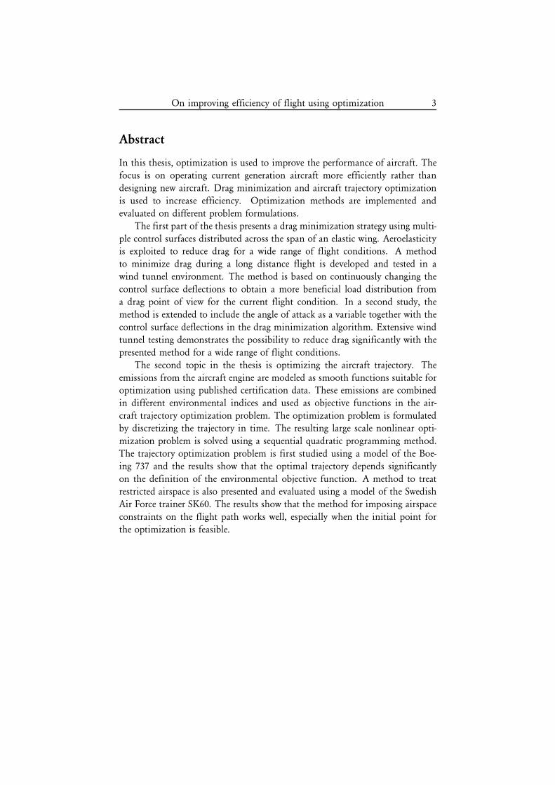
Abstract
In this thesis, optimization is used to improve the performance of aircraft. The
focus is on operating current generation aircraft more efficiently rather than
designing new aircraft. Drag minimization and aircraft trajectory optimization
is used to increase efficiency. Optimization methods are implemented and
evaluated on different problem formulations.
The first part of the thesis presents a drag minimization strategy using multi-
ple control surfaces distributed across the span of an elastic wing. Aeroelasticityis exploited to reduce drag for a wide range of flight conditions. A method
to minimize drag during a long distance flight is developed and tested in a
wind tunnel environment. The method is based on continuously changing the
control surface deflections to obtain a more beneficial load distribution from
a drag point of view for the current flight condition. In a second study, the
method is extended to include the angle of attack as a variable together with the
control surface deflections in the drag minimization algorithm. Extensive wind
tunnel testing demonstrates the possibility to reduce drag significantly with the
presented method for a wide range of flight conditions.
The second topic in the thesis is optimizing the aircraft trajectory. The
emissions from the aircraft engine are modeled as smooth functions suitable foroptimization using published certification data. These emissions are combined
in different environmental indices and used as objective functions in the air-
craft trajectory optimization problem. The optimization problem is formulated
by discretizing the trajectory in time. The resulting large scale nonlinear opti-
mization problem is solved using a sequential quadratic programming method.
The trajectory optimization problem is first studied using a model of the Boe-
ing 737 and the results show that the optimal trajectory depends significantly
on the definition of the environmental objective function. A method to treat
restricted airspace is also presented and evaluated using a model of the Swedish
Air Force trainer SK60. The results show that the method for imposing airspace
constraints on the flight path works well, especially when the initial point for
the optimization is feasible.
On improving efficiency of flight using optimization 5
Dissertation
This doctoral thesis is based on a brief introduction to the area of research and
the following appended papers:
Paper A
M. Jacobsen. Real time drag minimization using redundant control surfaces.
On improving efficiency of flight using optimization 9
Introduction
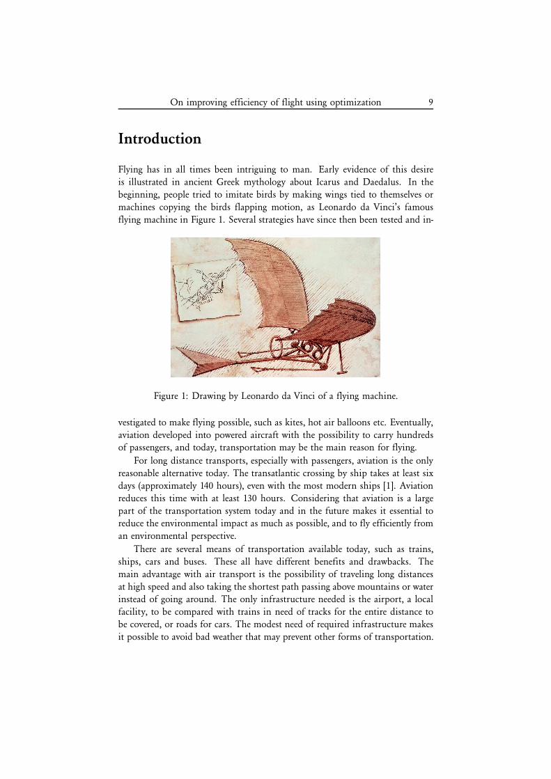
Flying has in all times been intriguing to man. Early evidence of this desire
is illustrated in ancient Greek mythology about Icarus and Daedalus. In the
beginning, people tried to imitate birds by making wings tied to themselves or
machines copying the birds flapping motion, as Leonardo da Vinci’s famous
flying machine in Figure 1. Several strategies have since then been tested and in-
Figure 1: Drawing by Leonardo da Vinci of a flying machine.
vestigated to make flying possible, such as kites, hot air balloons etc. Eventually,
aviation developed into powered aircraft with the possibility to carry hundredsof passengers, and today, transportation may be the main reason for flying.
For long distance transports, especially with passengers, aviation is the only
reasonable alternative today. The transatlantic crossing by ship takes at least six
days (approximately 140 hours), even with the most modern ships [1]. Aviation
reduces this time with at least 130 hours. Considering that aviation is a large
part of the transportation system today and in the future makes it essential toreduce the environmental impact as much as possible, and to fly efficiently from
an environmental perspective.
There are several means of transportation available today, such as trains,
ships, cars and buses. These all have different benefits and drawbacks. The
main advantage with air transport is the possibility of traveling long distances
at high speed and also taking the shortest path passing above mountains or waterinstead of going around. The only infrastructure needed is the airport, a local
facility, to be compared with trains in need of tracks for the entire distance to
be covered, or roads for cars. The modest need of required infrastructure makes
it possible to avoid bad weather that may prevent other forms of transportation.
10 M. Jacobsen
It is also possible for an aircraft to store energy in altitude and use it to glide
long distances if designed properly.
With all forms of transportation, environmental issues need to be addressed.
For aviation, climate change and stratospheric ozone depletion are the mainissues discussed today. With increasing fuel prices, much has already been
done on the efficiency of aircraft. Modern jets are relatively fuel efficient with
approximately 0.035 l per passenger km [2], which is comparable to cars despite
the much higher speed.
Aviation and the environment
During the last decades, there has been a significant growth in air traffic. The
annual growth rate is estimated to continue with around 5% for the coming
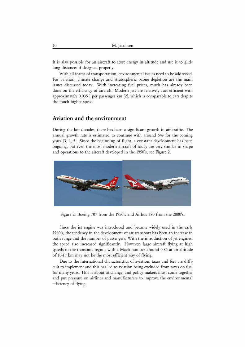
years [3, 4, 5]. Since the beginning of flight, a constant development has been
ongoing, but even the most modern aircraft of today are very similar in shape
and operations to the aircraft developed in the 1950’s, see Figure 2.
Figure 2: Boeing 707 from the 1950’s and Airbus 380 from the 2000’s.
Since the jet engine was introduced and became widely used in the early
1960’s, the tendency in the development of air transport has been an increase in
both range and the number of passengers. With the introduction of jet engines,
the speed also increased significantly. However, large aircraft flying at high
speeds in the transonic regime with a Mach number around 0.85 at an altitude
of 10-13 km may not be the most efficient way of flying.
Due to the international characteristics of aviation, taxes and fees are diffi-cult to implement and this has led to aviation being excluded from taxes on fuel
for many years. This is about to change, and policy makers must come together
and put pressure on airlines and manufacturers to improve the environmental
efficiency of flying.
On improving efficiency of flight using optimization 11
Aviation today and in the future
Before the 1980’s, aircraft were designed mainly with range as the objective [6],
which in turn gave a lower fuel consumption without being the primary tar-
get. This is most likely due to the historically very low fuel costs. Now, thishas started to change, and fuel efficiency and emissions are considered impor-
tant parameters when designing new aircraft. The environmental awareness has
increased dramatically during the last years, even though Arrhenius described
what is today known as the greenhouse effect already in 1896 [7]. Nevertheless,
it is difficult to connect a certain human activity to climate change, but it is
now rather well understood and accepted that burning fossil fuels emits carbon
dioxide that contributes to climate change.
The amount of fuel used in aviation is approximately 2-3% of the total
amount of fossil fuels burnt today [8]. The transportation sector uses about
20-25% of all fossil fuels, which means that aviation uses about 13% of all fuels
used for transportation. To reduce these figures, new technology development
is of importance. The intergovernmental panel on climate change (IPCC) has
considered several different scenarios for air traffic in the future, but common to
all these scenarios is a continuous growth in air traffic. During the last decades
of development, a clear trend has been that propeller has changed to jet, but also
that the specific fuel consumption is becoming smaller and smaller, which is a
good trend. Aerodynamics has been refined, and new light-weight materials, like
carbon fiber composites, are already being used to a large extent in new aircraftdesigns, such as the Boeing 787.
Today, design of new aircraft is driven by cost. Operators are interested in
the operating cost, and this does not only include fuel cost, but also different fees
and taxes. Manufacturers also have to consider airport requirements. According
to Peeters et al. [6], the Airbus 380 would have a different design if the aircraft
was designed only for fuel efficiency. The wings would have had larger span, but
due to airport handling constraints of a maximum span of 80 m, the planformwas designed for this requirement. Without those restrictions the aircraft could
have been 12% more fuel efficient. In future designs, foldable wing tips could
be used to combine the airport requirements with more fuel efficient designs.
This would increase the manufacturing cost, but may lower the fuel cost.
There is a continuous development of aviation. In 1999, IPCC summarized
technology improvements to future aircraft in the special report on aviation and
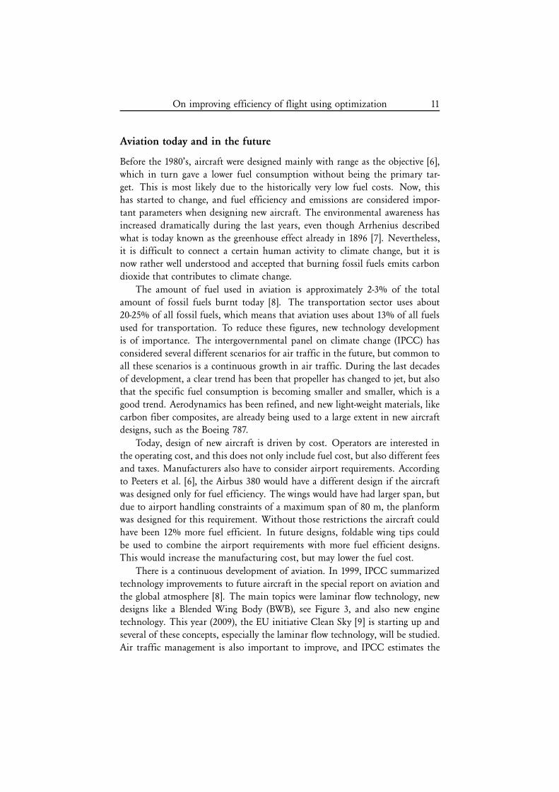
the global atmosphere [8]. The main topics were laminar flow technology, newdesigns like a Blended Wing Body (BWB), see Figure 3, and also new engine
technology. This year (2009), the EU initiative Clean Sky [9] is starting up and
several of these concepts, especially the laminar flow technology, will be studied.
Air traffic management is also important to improve, and IPCC estimates the
12 M. Jacobsen
Figure 3: Blended wing body design.
reduction in fuel consumption only due to increased efficiency in air traffic
management to be between 8 and 18%.
Many of the concepts in the IPCC report and also in the Clean Sky project
are small adjustments to already existing aircraft designs. It may, however, be
essential for aviation in the future to make larger changes. Considering the
great efficiency development in high performance gliders, it may be possible to
use knowledge from this area even in commercial aircraft. Larger aspect ratios
and using aeroelasticity to optimize performance over a wider range of flight
conditions may be possible in the future. Long slender wings on smaller aircraftand lower speeds may be the future for environmentally friendly air transports
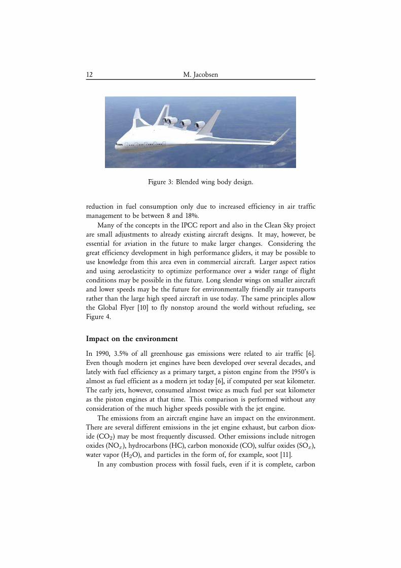
rather than the large high speed aircraft in use today. The same principles allow
the Global Flyer [10] to fly nonstop around the world without refueling, see
Figure 4.
Impact on the environment
In 1990, 3.5% of all greenhouse gas emissions were related to air traffic [6].
Even though modern jet engines have been developed over several decades, and
lately with fuel efficiency as a primary target, a piston engine from the 1950’s is
almost as fuel efficient as a modern jet today [6], if computed per seat kilometer.
The early jets, however, consumed almost twice as much fuel per seat kilometer
as the piston engines at that time. This comparison is performed without any
consideration of the much higher speeds possible with the jet engine.
The emissions from an aircraft engine have an impact on the environment.
There are several different emissions in the jet engine exhaust, but carbon diox-ide (CO2) may be most frequently discussed. Other emissions include nitrogen
water vapor (H2O), and particles in the form of, for example, soot [11].
In any combustion process with fossil fuels, even if it is complete, carbon
On improving efficiency of flight using optimization 13
Figure 4: The Virgin Atlantic Global Flyer (courtesy of Jim Sugar).
dioxide and water vapor will be produced. These have, therefore, not always been
considered pollutant emissions, but in recent years the climate effects caused by
greenhouse gases have been better understood. Carbon dioxide and water vapor
can only be reduced by burning less fuel. Both carbon monoxide and unburned
hydrocarbons are toxic to humans and can, in large concentrations, even causedeath. Hydrocarbons also contribute to photochemical smog when combined
with nitrogen oxides.
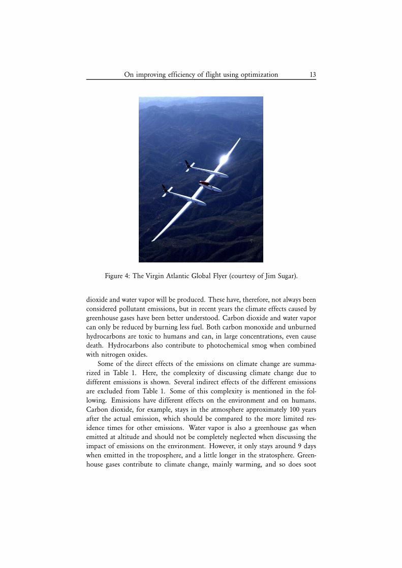
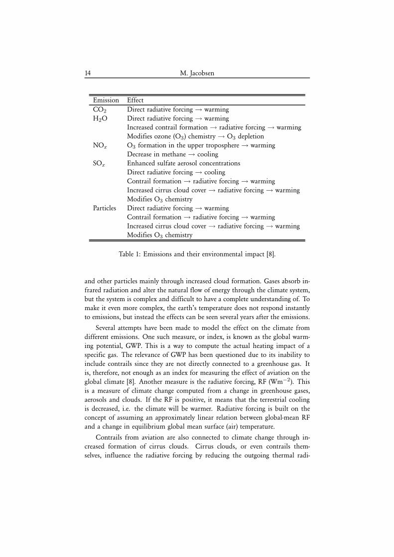
Some of the direct effects of the emissions on climate change are summa-
rized in Table 1. Here, the complexity of discussing climate change due to
different emissions is shown. Several indirect effects of the different emissions
are excluded from Table 1. Some of this complexity is mentioned in the fol-
lowing. Emissions have different effects on the environment and on humans.
Carbon dioxide, for example, stays in the atmosphere approximately 100 years
after the actual emission, which should be compared to the more limited res-
idence times for other emissions. Water vapor is also a greenhouse gas whenemitted at altitude and should not be completely neglected when discussing the
impact of emissions on the environment. However, it only stays around 9 days
when emitted in the troposphere, and a little longer in the stratosphere. Green-
house gases contribute to climate change, mainly warming, and so does soot
Table 1: Emissions and their environmental impact [8].
and other particles mainly through increased cloud formation. Gases absorb in-
frared radiation and alter the natural flow of energy through the climate system,but the system is complex and difficult to have a complete understanding of. To
make it even more complex, the earth’s temperature does not respond instantly
to emissions, but instead the effects can be seen several years after the emissions.
Several attempts have been made to model the effect on the climate from
different emissions. One such measure, or index, is known as the global warm-
ing potential, GWP. This is a way to compute the actual heating impact of a
specific gas. The relevance of GWP has been questioned due to its inability to
include contrails since they are not directly connected to a greenhouse gas. It
is, therefore, not enough as an index for measuring the effect of aviation on the
global climate [8]. Another measure is the radiative forcing, RF (Wm−2). This
is a measure of climate change computed from a change in greenhouse gases,
aerosols and clouds. If the RF is positive, it means that the terrestrial cooling
is decreased, i.e. the climate will be warmer. Radiative forcing is built on theconcept of assuming an approximately linear relation between global-mean RF
and a change in equilibrium global mean surface (air) temperature.
Contrails from aviation are also connected to climate change through in-
creased formation of cirrus clouds. Cirrus clouds, or even contrails them-
selves, influence the radiative forcing by reducing the outgoing thermal radi-
On improving efficiency of flight using optimization 15
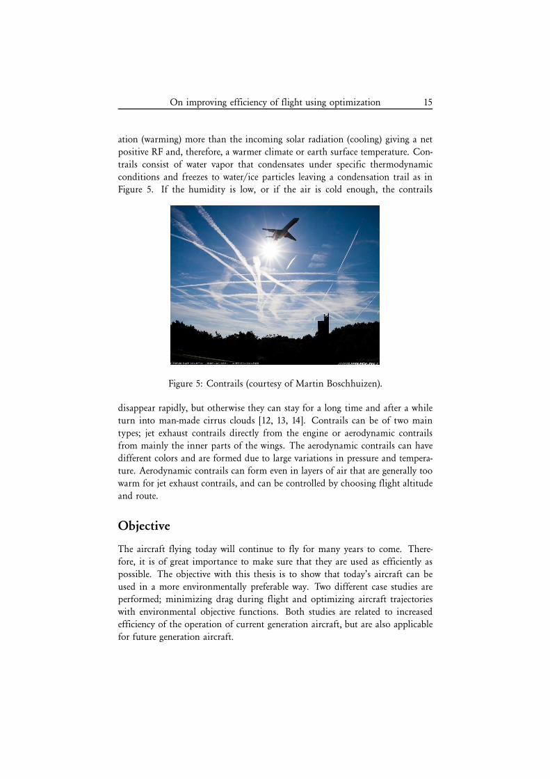
ation (warming) more than the incoming solar radiation (cooling) giving a net
positive RF and, therefore, a warmer climate or earth surface temperature. Con-
trails consist of water vapor that condensates under specific thermodynamic
conditions and freezes to water/ice particles leaving a condensation trail as inFigure 5. If the humidity is low, or if the air is cold enough, the contrails
Figure 5: Contrails (courtesy of Martin Boschhuizen).
disappear rapidly, but otherwise they can stay for a long time and after a while
turn into man-made cirrus clouds [12, 13, 14]. Contrails can be of two main
types; jet exhaust contrails directly from the engine or aerodynamic contrails
from mainly the inner parts of the wings. The aerodynamic contrails can have
different colors and are formed due to large variations in pressure and tempera-
ture. Aerodynamic contrails can form even in layers of air that are generally too
warm for jet exhaust contrails, and can be controlled by choosing flight altitude
and route.
Objective
The aircraft flying today will continue to fly for many years to come. There-
fore, it is of great importance to make sure that they are used as efficiently as
possible. The objective with this thesis is to show that today’s aircraft can be
used in a more environmentally preferable way. Two different case studies areperformed; minimizing drag during flight and optimizing aircraft trajectories
with environmental objective functions. Both studies are related to increased
efficiency of the operation of current generation aircraft, but are also applicable
for future generation aircraft.
16 M. Jacobsen
The objective of the drag minimization concept in this thesis is to develop
a method that exploits the already existing control surfaces on the aircraft to
reduce drag while maintaining the current state. Less drag requires less thrust
for propulsion, which also means less fuel consumed. The aircraft trajectoriesare studied to decrease emissions during a flight. The objective with this part
of the thesis is to be able to model aircraft emissions to make them suitable for
optimization. The main goal is to optimize the aircraft trajectories to minimize
environmental impact. Before describing the contributions and results of this
thesis, some background will be given on drag, emissions and optimization,
which is the main tool for the studies.
Drag
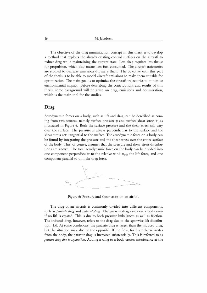
Aerodynamic forces on a body, such as lift and drag, can be described as com-
ing from two sources, namely surface pressure p and surface shear stress τ , asillustrated in Figure 6. Both the surface pressure and the shear stress will vary
over the surface. The pressure is always perpendicular to the surface and the
shear stress acts tangential to the surface. The aerodynamic force on a body can
be found by integrating the pressure and the shear stress over the entire surface
of the body. This, of course, assumes that the pressure and shear stress distribu-
tions are known. The total aerodynamic force on the body can be divided intoone component perpendicular to the relative wind u∞, the lift force, and one
component parallel to u∞, the drag force.
u∞
p
τ
Figure 6: Pressure and shear stress on an airfoil.
The drag of an aircraft is commonly divided into different components,
such as parasite drag and induced drag. The parasite drag exists on a body even
if no lift is created. This is due to both pressure imbalances as well as friction.
The induced drag, however, refers to the drag due to the spanwise lift distribu-tion [15]. At some conditions, the parasite drag is larger than the induced drag,
but the situation may also be the opposite. If the flow, for example, separates
from the body, the parasite drag is increased substantially. This is referred to as
pressure drag due to separation. Adding a wing to a body creates interference at the
On improving efficiency of flight using optimization 17
intersection between the parts. This can cause interference drag on the body. At
transonic speeds, shock waves appear and this creates wave drag due to the total
pressure loss across the shock wave [16].
There are different approaches when investigating the drag of an object. The
oldest approach is to use experimental facilities, such as wind or water tunnels,
to investigate different fluid phenomena. Another approach is to use numerical
techniques and solve the fundamental governing equations. This is commonly
referred to as computational fluid dynamics, CFD. Both approaches are fre-quently used today together with ’handbook methods’, such as Hoerner [17].
Drag reduction strategies
Reducing drag has always been of great interest for many different applications.
Lower drag generally means lower required thrust for an aircraft. Early on in
the design process drag is considered an important parameter and much work
is put on reducing drag in the aeronautical industry.
Much work is also put on weight reduction today to allow for more payload
or reducing the required lift giving less induced drag. Structural weight reduc-
tion often leads to more flexible wings, and a European research program called
Active Aeroelastic Aircraft Structures (3AS) [18], studied concepts that exploit
the increased aeroelastic effects in a beneficial way. As part of this project, dif-
ferent techniques for drag minimization, or drag reduction, were studied. Theconcept of using distributed control surfaces across the span to change the lift
distribution depending on the flight condition was used in a study by Eller and
Heinze [19]. Here, the induced drag was minimized on a slender wing with 20
control surfaces. It was also shown that significant drag reduction was possi-
ble using only a few of these control surfaces making it more realistic from a
manufacturing point of view. This study was performed using both numerical
predictions and experimental validation of the drag. A similar study, although
only numerical, was performed recently by Kolonay and Eastep [20] also reduc-
ing the induced drag for different flight conditions and for two different wing
configurations.
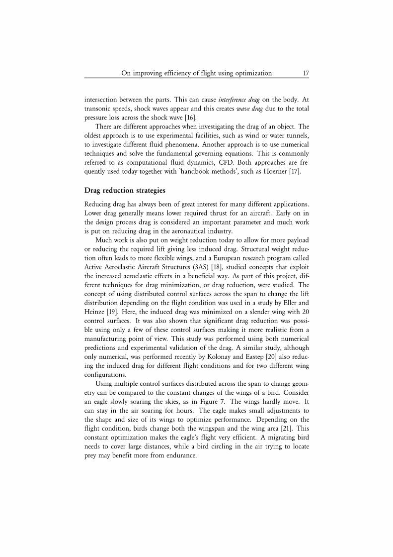
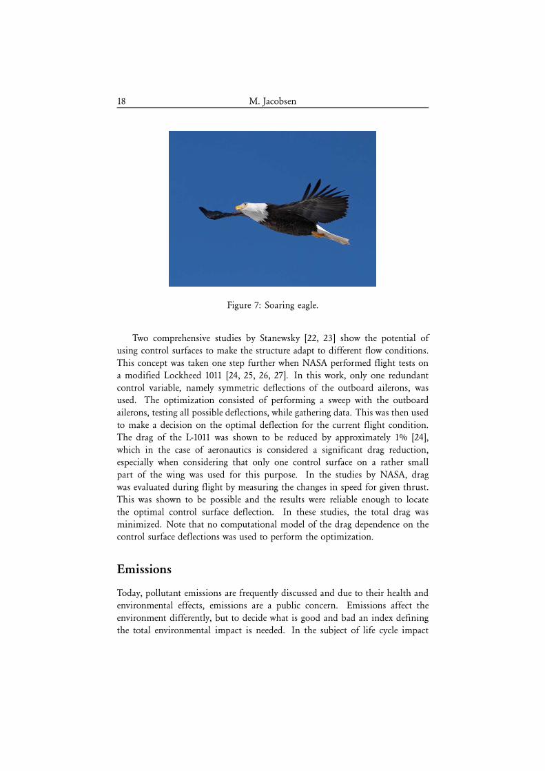
Using multiple control surfaces distributed across the span to change geom-
etry can be compared to the constant changes of the wings of a bird. Consider
an eagle slowly soaring the skies, as in Figure 7. The wings hardly move. It
can stay in the air soaring for hours. The eagle makes small adjustments to
the shape and size of its wings to optimize performance. Depending on theflight condition, birds change both the wingspan and the wing area [21]. This
constant optimization makes the eagle’s flight very efficient. A migrating bird
needs to cover large distances, while a bird circling in the air trying to locate
prey may benefit more from endurance.
18 M. Jacobsen
Figure 7: Soaring eagle.
Two comprehensive studies by Stanewsky [22, 23] show the potential of
using control surfaces to make the structure adapt to different flow conditions.
This concept was taken one step further when NASA performed flight tests on
a modified Lockheed 1011 [24, 25, 26, 27]. In this work, only one redundant
control variable, namely symmetric deflections of the outboard ailerons, wasused. The optimization consisted of performing a sweep with the outboard
ailerons, testing all possible deflections, while gathering data. This was then used
to make a decision on the optimal deflection for the current flight condition.
The drag of the L-1011 was shown to be reduced by approximately 1% [24],
which in the case of aeronautics is considered a significant drag reduction,
especially when considering that only one control surface on a rather small
part of the wing was used for this purpose. In the studies by NASA, drag
was evaluated during flight by measuring the changes in speed for given thrust.
This was shown to be possible and the results were reliable enough to locate
the optimal control surface deflection. In these studies, the total drag was
minimized. Note that no computational model of the drag dependence on thecontrol surface deflections was used to perform the optimization.
Emissions
Today, pollutant emissions are frequently discussed and due to their health and
environmental effects, emissions are a public concern. Emissions affect the
environment differently, but to decide what is good and bad an index defining
the total environmental impact is needed. In the subject of life cycle impact
On improving efficiency of flight using optimization 19
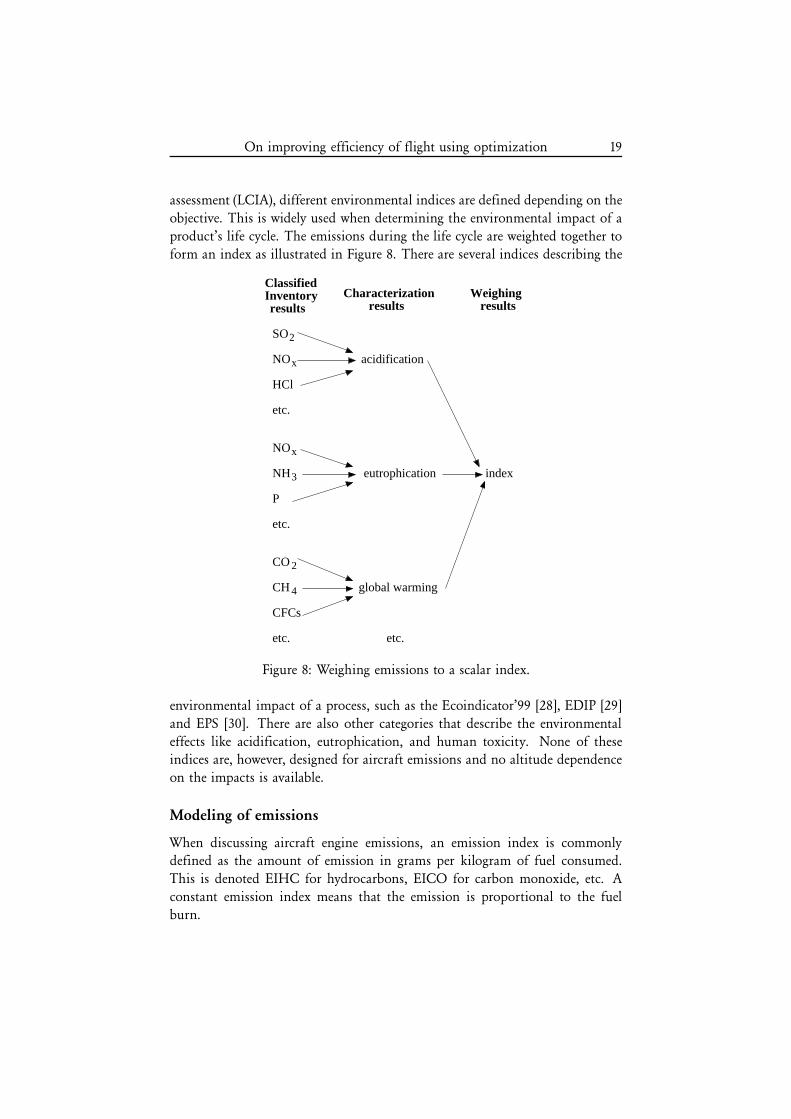
assessment (LCIA), different environmental indices are defined depending on the
objective. This is widely used when determining the environmental impact of a
product’s life cycle. The emissions during the life cycle are weighted together to
form an index as illustrated in Figure 8. There are several indices describing the
etc.
P
etc.
CFCs
etc.
NOx
NH3
CO 2
CH
eutrophication
global warming
etc.
index
ClassifiedInventoryresults
Characterizationresults
SO2
NOx
HCl
acidification
4
resultsWeighing
Figure 8: Weighing emissions to a scalar index.
environmental impact of a process, such as the Ecoindicator’99 [28], EDIP [29]
and EPS [30]. There are also other categories that describe the environmental
effects like acidification, eutrophication, and human toxicity. None of theseindices are, however, designed for aircraft emissions and no altitude dependence
on the impacts is available.
Modeling of emissions
When discussing aircraft engine emissions, an emission index is commonlydefined as the amount of emission in grams per kilogram of fuel consumed.
This is denoted EIHC for hydrocarbons, EICO for carbon monoxide, etc. A
constant emission index means that the emission is proportional to the fuel
burn.
20 M. Jacobsen
Today, certification of aircraft engines with respect to noise and emissions
is required. The engine manufacturers perform measurements of the emissions
under sea level static, standard day conditions for different power settings. The
certification data is built on these measurements, but to compute the emissionsduring an entire flight a more comprehensive model is needed.
There are different methods available for using sea level measured emission
data and correcting it for altitude and Mach number. Two methods are described
here, the T3-P3 method [31] and the fuel flow method 2 [32]. The T3-P3 method
requires much knowledge of the engine internal parameters and this informationis rarely made publicly available. The fuel flow method 2, developed by the
Boeing Company, is derived from the T3-P3 method but only requires an engine
model that predicts the fuel flow. In the studies in this thesis, the Boeing fuel
flow method is used.
The T3-P3 method The T3-P3 method is a way to estimate the emission
indices, EI, for CO, HC and NOx using sea level emission indices and a pressure
correction for altitude. This method requires the temperature and the total
pressure at the combustor inlet, T3 and P3 , as well as the emission indices at
sea level as function of T3, that is EICOsl(T3), EIHCsl(T3) and EINOx,sl(T3).The emission index at altitude is determined by running a simulation with an
aircraft performance model to obtain thrust and fuel flow together with pressure
altitude, flight speed and ambient temperature. These data are then used asinput to the engine performance model, giving P3 and T3 for the current flight
condition. A pressure correction is used to transfer the sea level emission indices
to the correct altitude.
The fuel flow method 2 The T3-P3 method requires much knowledge about
the engine internal parameters, but the fuel flow method 2 is developed to model
the emission indices from more readily available data, such as the engine fuel
flow. A model of the sea level static emission indices is also needed as function
of the fuel flow. To obtain the emission indices for CO, HC and NOx at al-
titude, an aircraft performance model is used to compute the fuel flow for the
flight condition of interest. The corresponding pressure altitude, flight speed
and ambient temperature should also be computed. The fuel flow at altitude
is then corrected for temperature, pressure and Mach number to give a corre-
sponding fuel flow at sea level. The corrected fuel flow at sea level is used tofind the emission indices at sea level and these are then corrected for altitude
and humidity. A more extensive review of both methods is found in DuBois
and Paynter [32].
On improving efficiency of flight using optimization 21
The international civil aviation organization, ICAO, is an agency of the
United Nations that, among many other things, certifies commercial jet engines
for noise and emissions. Almost all countries in the world are members of
ICAO making it rather powerful. The ICAO engine standards are constantlyrevised to drive engine technology forward. The data for the certified engines is
collected in the comprehensive ICAO engine exhaust emission data bank [33].
The certification data consists of four data points where emissions are measured
at different thrust levels, which can be correlated to different fuel burn levels.
These four data points can be used to determine a model of the emissions as
function of fuel burn at sea level.
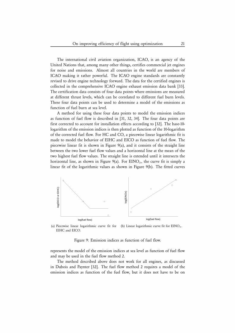
A method for using these four data points to model the emission indices
as function of fuel flow is described in [31, 32, 34]. The four data points are
first corrected to account for installation effects according to [32]. The base-10-
logarithm of the emission indices is then plotted as function of the 10-logarithm
of the corrected fuel flow. For HC and CO, a piecewise linear logarithmic fit ismade to model the behavior of EIHC and EICO as function of fuel flow. The
piecewise linear fit is shown in Figure 9(a), and it consists of the straight line
between the two lower fuel flow values and a horizontal line at the mean of the
two highest fuel flow values. The straight line is extended until it intersects the
horizontal line, as shown in Figure 9(a). For EINOx, the curve fit is simply a
linear fit of the logarithmic values as shown in Figure 9(b). The fitted curves
log(fuel flow)
log(
EIC
O o
r E
IHC
)
(a) Piecewise linear logarithmic curve fit forEIHC and EICO.
log(fuel flow)
log(
EIN
Ox)
(b) Linear logarithmic curve fit for EINOx.
Figure 9: Emission indices as function of fuel flow.
represents the model of the emission indices at sea level as function of fuel flowand may be used in the fuel flow method 2.
The method described above does not work for all engines, as discussed
in Dubois and Paynter [32]. The fuel flow method 2 requires a model of the
emission indices as function of the fuel flow, but it does not have to be on
22 M. Jacobsen
the logarithmic form as described above. Another approach, which has been
used in this thesis, is to model the emission indices as function of fuel flow as
smooth functions using polynomial B-splines [35, 36]. The advantage with this
representation is that the model is continuously differentiable to any chosenorder and there are efficient methods to evaluate both the function and its
derivatives once the splines have been defined. Approximating a spline to only
four data points from the certification data may, however, not give a correct
representation of the function. More data points would be beneficial to obtain
better insight to the function behavior.
An extensive study by NASA has been performed in order to investigate
the aircraft emissions, the aircraft particle emissions experiment (APEX) [37].
Here, a DC-8 aircraft equipped with four General Electric CFM56-2-C1 engines
is used as the test platform. This study investigated different fuel types and
the effect of thrust on the engine exhaust. The engine studied here is rather
similar to engines on several commercial aircraft of today, and it is assumed
that the general trends shown through the measurements in this study shouldhold for most commercial jet engines of similar type. This data can, therefore,
be used to approximate the splines to obtain a model of the emissions suitable
for optimization.
Optimization
The main tool in this thesis is optimization. When used correctly, it can be a
powerful tool, and often the solution is far from expected. When defining an
optimization problem, good and bad must somehow be defined. This is com-
monly referred to as the objective function, which should either be minimized
or maximized. Also, the variables usually have to satisfy some constraints that
can be linear or nonlinear functions. This can be expressed mathematically as
minx
f(x) (1)
subject to g(x) ≤ 0,
where x denotes the variables, f(x) the scalar valued objective function, and
g(x) the vector of constraints. Solving the optimization problem means find-ing the variables x that minimize the objective function while satisfying the
constraints.
There are several different types of solution methods for any given opti-
mization problem. Depending on the characteristics of the problem, such as the
number of variables and the differentiability of the functions, different methods
On improving efficiency of flight using optimization 23
are suitable. In this thesis, two rather different problems have been studied and
the optimization techniques used are described here.
Optimization with wind tunnel measurements
The problem of minimizing drag during flight is discussed here. The objective
function is in this case the drag coefficient CD, which is defined as the drag
force, D, normalized with the dynamic pressure, q∞, and the aerodynamic
reference wing area, S, i.e. CD = D/(q∞S). The dynamic pressure is defined
as q∞ = ρu2∞
/2 with ρ as the density of the air and u∞ as the freestreamvelocity. The dynamic pressure is essentially a measure of the kinetic energy of
the airstream. The constraints in the optimization problem include keeping the
lift coefficient, CL, constant as well as keeping the control surface deflections,
δi, and the angle of attack, α, within some given bounds. The lift coefficient is
defined in the same way as the drag coefficient but with the lift force L instead
of D. The optimization problem can be written as
minα, δ
CD(α, δ) (2)
subject to CL(α, δ) = CLset,
αl ≤ α ≤ αu,
δl ≤ δ ≤ δu,
where αl, δl and αu, δu are the lower and upper bounds on the angle of attackand the control surface deflections. The constant lift coefficient, given by CLset,
is essentially defined by the altitude at which the aircraft is flying, the mass and
the airspeed. The solution to a problem of this form is given by the optimal
angle of attack α∗ and the optimal control surface deflections δ∗ that minimizes
the drag coefficient while satisfying the constraints.
Solution strategy
In the drag minimization studies in this thesis, the objective is the measured
drag. Hence, no computational model of the drag coefficient is used. Using
measured or numerically computed drag is a choice, and several studies mini-
mizing the numerical drag have been performed, as discussed previously. Here,
the focus is similar to the concept studied and tested by NASA [24], but focusingon a more sophisticated optimization technique and using more variables.
Many gradient based techniques for solving constrained optimization prob-
lems are available today and they are generally very effective. Gradients can be
determined from measurements by finite differences, but measured data contains
24 M. Jacobsen
noise that may give inaccurate and unreliable results. Therefore, a derivative-free
approach is desired. However, solving (2) without the explicit use of gradients is
not straightforward.
The optimality conditions involve derivatives of both the objective functionand the constraints [38]. Hence, the question is if it is even possible to find
an optimal solution without the use of derivatives. Several methods exist that
try to do just this. The wide class of optimization techniques that does not use
derivatives are referred to as derivative-free methods [39, 40, 41, 42]. There are
two main groups of derivative-free methods; methods that construct approxi-
mations of different kinds to the objective function, and direct search methods
that only compare function values. The distinction between these two groups
is not always clear. Many of the derivative-free methods are practical only for
unconstrained optimization, but it is possible to generalize some of the methods
to include constraints.
A widely used method for solving unconstrained optimization problemswithout explicit use of gradients is the response surface methodology (RSM) [43].
This is a method that samples the objective function, or response function, at
designated points close to the current iterate and performs regression analysis to
approximate a local linear (or quadratic) model of the response function. This
method has been used in many engineering applications [44, 45, 46]. If RSM
is to be used successfully, it is of great importance to choose the sample points
with care. Using a full quadratic model may give a rather good picture of the
actual objective function, but it is also costly since it requires many function
evaluations to approximate the response surface accurately if the number of
variables is large.
Another method is the popular Nelder-Mead simplex algorithm [47]. It isa direct search method and it works well in many cases. Unfortunately, it may
also fail [39]. This has led to a lot of work analyzing the asymptotic behavior of
the Nelder-Mead method [48]. It can be shown that the algorithm is robust and
will converge to a stationary point in R1, but in higher dimensions convergence
has not been proven.
There are, however, other direct search methods that are known to be robust.
A review on a class of methods known as generating set search methods (GSS)
is found in Kolda et al. [40]. These methods can be shown to be reliable in the
sense that convergence results can be obtained, local rates of convergence can be
established as well as how the performance is affected by the dimension of the
problem. To solve the drag minimization problem in this thesis, a GSS methodhas been used that can be generalized to take linear inequality constraints into
account, see [49, 50, 51].
Direct search methods are, although robust, still slow and should only be
On improving efficiency of flight using optimization 25
used when necessary. The solution can generally be found more efficiently if
gradients can be computed or approximated. The performance is also degraded
quickly when the number of variables is increased or when the problem is badly
scaled [52].
Trajectory optimization
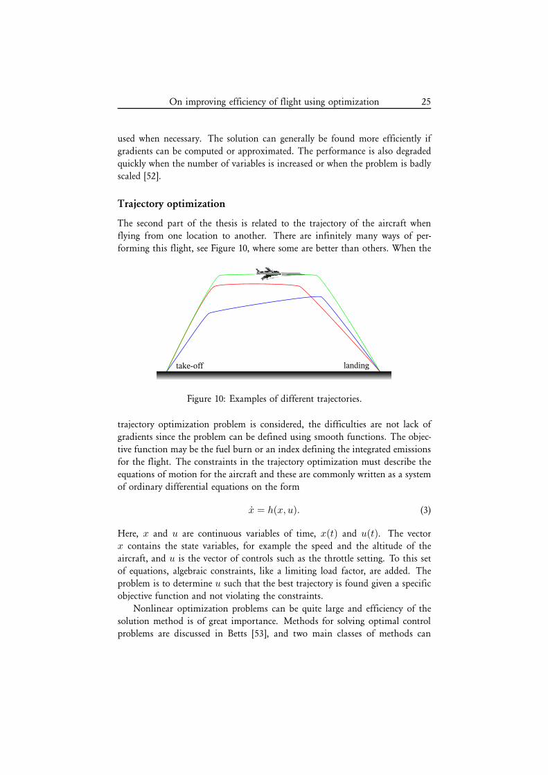
The second part of the thesis is related to the trajectory of the aircraft when
flying from one location to another. There are infinitely many ways of per-
forming this flight, see Figure 10, where some are better than others. When the
Figure 10: Examples of different trajectories.
trajectory optimization problem is considered, the difficulties are not lack of
gradients since the problem can be defined using smooth functions. The objec-
tive function may be the fuel burn or an index defining the integrated emissions
for the flight. The constraints in the trajectory optimization must describe the
equations of motion for the aircraft and these are commonly written as a system
of ordinary differential equations on the form
x = h(x, u). (3)
Here, x and u are continuous variables of time, x(t) and u(t). The vectorx contains the state variables, for example the speed and the altitude of the
aircraft, and u is the vector of controls such as the throttle setting. To this set
of equations, algebraic constraints, like a limiting load factor, are added. The
problem is to determine u such that the best trajectory is found given a specific
objective function and not violating the constraints.
Nonlinear optimization problems can be quite large and efficiency of the
solution method is of great importance. Methods for solving optimal control
problems are discussed in Betts [53], and two main classes of methods can
26 M. Jacobsen
be identified, direct and indirect methods. The indirect methods are generally
more difficult to implement and good theoretical knowledge about the problem
formulation is required in order to obtain good results.
To use a direct method, on the other hand, the equations are discretized
and formulated as one large optimization problem. Here, the equations of mo-
tion (3) are discretized in time using collocation, as first suggested by Hargraves
and Paris [54]. This gives a problem described as a set of nonlinear algebraicequations on the form
maxy
f(y)(4)
subject to l ≤
c(y)Cyy
≤ u,
where f is the objective function and the variables y consist of the discretized
state and control variables. The constraints c(y) are the discretized equations
of motion and algebraic constraints for the aircraft. The matrix C may de-fine linear continuity constraints, if the problem is defined using a multi stage
formulation [55]. The vectors containing the lower and upper bounds of the
constraints are denoted l and u respectively.
To solve the nonlinear optimization problem (4), several different optimiza-
tion techniques may be used. However, the problem is usually rather large and
nonconvex, making it difficult to solve and the method should be chosen with
care. In general, it is not possible to find a unique global minimizer to a non-
linear optimization problem. It is, therefore, of great importance to use already
known information about the solution. For example, using a feasible starting
guess may speed up the solution process quite drastically.
Due to the collocation technique used to discretize the equations, sparsity
could be exploited when solving the optimization problem (4). In the trajec-
tory optimization studies included in this thesis, SNOPT by Gill et al. [56] is
used. This is a sequential quadratic programming (SQP) algorithm that solves
a quadratic subproblem at each major iteration. The algorithm uses Quasi-
Newton approximations to the required second derivative information, and itefficiently exploits sparsity in the constraint Jacobian when solving the quadratic
subproblem. This formulation and solution strategy has been used successfully
in previous studies at the Department of Aeronautical and Vehicle engineering,
see for example Ringertz [57] and Norsell [58].
On improving efficiency of flight using optimization 27
Summary of appended papers
The aircraft flying today will keep flying for several years to come. This means
that it is of great importance to use the already existing aircraft in a way that
reduces the environmental impact. This can be performed through various new
technology concepts that can be incorporated into existing aircraft, and one such
improvement, drag minimization during flight, is studied in the first part of the
thesis. This is covered by papers A and B. An approach to optimize trajectories
for increased environmental efficiency is presented in papers C and D.
Drag minimization
It will always be beneficial to reduce drag of an aircraft. Less drag results in less
thrust needed to keep the aircraft at a certain speed. The first two papers in
this thesis, papers A and B, discuss a drag reduction scheme that can be used
on existing aircraft with only minor changes to the hardware, or for fly-by-wire
aircraft, only software changes. The concept presented is built on the hypothesisthat the aircraft is not optimized for all flight conditions during a long flight.
For example, as mass is reduced when fuel is burnt, the lift coefficient changes
and if the wings are elastic, so does the deformation. This may result in a less
beneficial load distribution from a drag perspective.
To affect the drag during flight, the control surfaces that already exist on any
transport aircraft today can be used. Since only two variables are theoretically
required to maintain altitude and speed, there will be several redundant control
surfaces available on most modern aircraft. If all control surfaces are used
continuously, lift can be kept constant while drag is minimized.
The work presented in this thesis does not focus on the implementation in a
real aircraft, but instead the main focus is on using a more advanced algorithm
to solve the optimization problem. Already when using two variables, testing
all possible combinations becomes very time consuming and the need for a
more sophisticated algorithm is obvious. Emphasis is also put on satisfying
constraints while minimizing drag.
Paper A discusses the drag minimization problem and how to formulate
it. Different strategies for choosing an appropriate optimization technique are
discussed and a derivative-free approach is implemented. The implementationof the method is described in detail, and some preliminary wind tunnel tests
are performed to investigate the performance of the algorithm on the specific
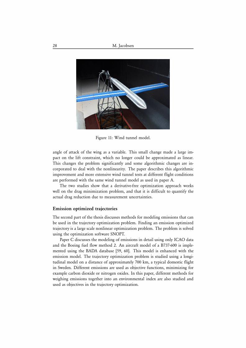
problem. Wind tunnel tests are performed on a wing with 16 individual control
surfaces distributed across the span on both the leading and trailing edges, see
Figure 11.
In paper B, the drag minimization algorithm is enhanced to include the
28 M. Jacobsen
Figure 11: Wind tunnel model.
angle of attack of the wing as a variable. This small change made a large im-
pact on the lift constraint, which no longer could be approximated as linear.
This changes the problem significantly and some algorithmic changes are in-
corporated to deal with the nonlinearity. The paper describes this algorithmicimprovement and more extensive wind tunnel tests at different flight conditions
are performed with the same wind tunnel model as used in paper A.
The two studies show that a derivative-free optimization approach works
well on the drag minimization problem, and that it is difficult to quantify the
actual drag reduction due to measurement uncertainties.
Emission optimized trajectories
The second part of the thesis discusses methods for modeling emissions that can
be used in the trajectory optimization problem. Finding an emission optimized
trajectory is a large scale nonlinear optimization problem. The problem is solved
using the optimization software SNOPT.
Paper C discusses the modeling of emissions in detail using only ICAO data
and the Boeing fuel flow method 2. An aircraft model of a B737-600 is imple-
mented using the BADA database [59, 60]. This model is enhanced with the
emission model. The trajectory optimization problem is studied using a longi-
tudinal model on a distance of approximately 700 km, a typical domestic flightin Sweden. Different emissions are used as objective functions, minimizing for
example carbon dioxide or nitrogen oxides. In this paper, different methods for
weighing emissions together into an environmental index are also studied and
used as objectives in the trajectory optimization.
On improving efficiency of flight using optimization 29
In paper D, a three-dimensional model of the SK60 is used. Here, the
approach to an airfield is studied from an environmental perspective. In this
case, a new type of constraint is added to account for no-fly zones, for example
avoiding flying directly above urban areas to avoid noise and emissions tooclose to human beings. The airspace constraints are also treated on a more long
distance flight with the SK60 from Stockholm to Visby, where a large restricted
airspace is encountered on the way.
The results from the two studies show that it is possible to model the
emissions to make it possible to include them in trajectory optimization. The
optimal trajectories differ significantly when different emissions or indices are
minimized. Minimizing emissions of carbon dioxide is the same as minimizing
the fuel burn during the flight. Generally the solution shows that lower speeds
may be better from an environmental perspective, as well as flying at higher
altitudes.
Discussion
The concepts presented in this thesis are related to the operations of aircraft.
This technology can be used on the aircraft of today, but it is not restricted in
any way and would most likely be useful on future aircraft as well.
The drag minimization technique presented in the first part of this thesis
takes advantage of control surfaces that are available on most aircraft. The test
object is a rather nonconventional wing with 16 control surfaces that may lookrather different from a typical aircraft wing. However, the wing of the Airbus
340 has at least 20 control surfaces distributed across the span that could be used
to minimize drag during flight. The results from the experiments performed
in the wind tunnel at KTH show a potential for drag reduction when using
only a few control surfaces. This is coherent with the results from the NASA
test flights with the Lockheed 1011 where a one percent drag reduction could
be achieved using only one redundant control surface. The NASA reports also
show that it is, in fact, possible to evaluate drag during a flight with a real
aircraft. In the wind tunnel environment where the experiments presented in
this thesis are performed, drag is evaluated using measurement techniques that
are not available in real flight.
The validation experiments performed in the wind tunnel show drag reduc-
tion possibilities. However, more accurate measurements would be required toquantify the actual increase in performance using the proposed drag minimiza-
tion technique. Problems with repeatability and drift in the measured signals
make these tests difficult. A larger wind tunnel model with larger forces would
make the measurements more reliable. Some of these problems are directly re-
30 M. Jacobsen
lated to the low Reynolds numbers in the wind tunnel tests. A study by Selig
and McGranahan [61] shows that drag measurements on a clean airfoil varies
significantly for low Reynolds numbers making measurements difficult.
The wind tunnel model used in these studies has a low absolute value ofthe drag force, and trying to resolve changes in this already small force has been
a challenge. With a larger wind tunnel model, or more accurate measurement
equipment, several other optimization techniques could be tested and compared.
It would, for example, be of interest to compare the derivative-free GSS method
to a more standard gradient based technique.
As for the aircraft trajectories, including other emissions than carbon diox-
ide may be premature [62]. The focus here has been to show the possibility of
modeling the emissions to make them useful in trajectory optimization. There
are already taxes or landing fees at some airports depending on how much hy-
drocarbons the engine emits according to the certification data. This shows the
importance of also including other emissions in the optimized trajectories. Theresults presented here are not to be seen as environmentally preferred trajectories
since a more accurate aircraft model would be required as well as more aircraft
related environmental indices. The question about what is good and bad should
be answered by climatologists involved in atmospheric studies.
It is difficult to put fees or taxes on aircraft emissions due to its global
nature. Today, many such fees are regulated only with the help of engine
certification data. This strategy will not, however, put any pressure on making
the airlines operate the aircraft in a more environmentally friendly way. Without
economic policies related to the actual emissions of the regulated substances
chances are small that much will be done. Airlines operate in a way to minimize
the total cost, and if emissions are not directly included, it will not be takeninto account. A future strategy could, for example, be to use simple GPS data
and reverse engineering to compute the actual aircraft trajectory [63] and from
that how much emissions have actually been produced during the flight.
Taking one step back, aviation may not be the most fuel efficient way of
traveling today, but on long distances and across large oceans, it is the only
reasonable means of transportation. It is, therefore, essential to keep working
toward improved efficiency of flight. Great benefits could also come from
optimizing aviation as a whole including everything from engine, airframe and
operations, rather than looking at just one part.
On improving efficiency of flight using optimization 31
References
[1] Cunard Line, 2009-07-30. Web address http://www.cunard.com.
[2] IATA, 2009-07-30. Web address http://www.iata.org/whatwedo/environ-
ment/fuel efficiency.htm.
[3] ICAO News release, 2001. PIO 06/01.
[4] ICAO News release, 2008. PIO 16/08.
[5] ICAO News release, 2009. PIO 08/09.
[6] P. M. Peeters, J. Middel, and A. Hoolhorst. Fuel efficiency of commercial
aircraft. An overview of historical and future trends. Technical Report
NLR-CR-2005-669, National Aerospace Laboratory, 2005.
[7] S. Arrhenius. Varldarnas utveckling. Hugo Gebers Forlag, 1924.
[8] J. E. Penner, D. H. Lister, D. J. Griggs, D. J. Dokken, and M. McFarland,
editors. Aviation and the Global Atmosphere. Cambridge University Press,
1999.
[9] Clean Sky, 2009-07-30. EU project. Web address http://www.cleansky.eu/.
[10] Global Flyer, 2009-08-11. Web address http://www.scaled.com/projects/...
globalflyer.html.
[11] A. H. Lefebvre. Gas Turbine Combustion. Taylor & Francis, second edition,
1999.
[12] K. Gierens, B. Karcher, H. Mannstein, and B. Mayer. Aerodynamically in-
duced formation of contrails. Proceedings of the TAC-Conference, Oxford,
United Kingdom, June 2006.
[13] H. Mannstein, K. Gierens, and P. Spichtinger. How to avoid contrailcirrus. 1st CEAS European Air and Space Conference, CEAS-2007-709,
Berlin, Germany, September 2007.
[14] K. Gierens, B. Karcher, H. Mannstein, and B. Mayer. Aerodynamic con-
trails: Phenomenology and flow physics. Journal of the Atmospheric Sciences,
66:217–226, 2009.
[15] J. D. Anderson. Fundamentals of Aerodynamics. McGraw-Hill, 1991.
[16] J. D. Anderson. Modern Compressible Flow. McGraw-Hill, 2003.
32 M. Jacobsen
[17] S. F. Hoerner. Fluid-dynamic drag. Hoerner, 1965.
[18] J. Schweiger and A. Suleman. The European research project: ”Active Aeroe-
lastic Aircraft Structures”. CEAS/AIAA/NVvL International Forum on Aeroe-
lasticity and Structural Dynamics, Paper GE-10, Netherlands Association of
Aeronautical Engineers (NVvL), Amsterdam, The Netherlands, June 2003.
[19] D. Eller and S. Heinze. An approach to induced drag reduction with
experimental evaluation. Journal of Aircraft, 42(6):1478–1485, 2005.
[20] R. M. Kolonay and F. E. Eastep. Optimal scheduling of control surfaces on
flexible wings to reduce induced drag. Journal of Aircraft, 43(6):1655–1661,
2006.
[21] M. Rosen and A. Hedenstrom. Gliding flight in a jackdaw: A wind tunnel
study. The Journal of Experimental Biology, 204:1153–1166, 2001.
[22] E. Stanewsky. Adaptive wing and flow control technology. Progress in
Aerospace Sciences, 37(7):583–667, 2001.
[23] E. Stanewsky. Aerodynamic benefits of adaptive wing technology. Aerospace
Science and Technology, 4(7):439–452, 2000.
[24] G. B. Gilyard, J. Georgie, and J. S. Barnicki. Flight test of an adaptive
configuration optimization system for transport aircraft. Technical Report
NASA/TM-1999-206569, 1999.
[25] G. Gilyard. Development of a real-time transport performance optimiza-
[38] S. G. Nash and A. Sofer. Linear and Nonlinear Programming. McGraw-Hill,
1996.
[39] R. M. Lewis, V. J. Torczon, and M. W. Trosset. Direct search methods:
Then and now. Journal of Computational and Applied Mathematics, 124:191–
207, 2000.
[40] T. G. Kolda, R. M. Lewis, and V. J. Torczon. Optimization by direct search:
New perspectives on some classical and modern methods. SIAM Review,
45(3):385–482, 2003.
34 M. Jacobsen
[41] R. M. Lewis and V. J. Torczon. Pattern search methods for linearly con-
strained minimization. SIAM Journal on Optimization, 10(3):917–941, 2000.
[42] P. Hajela. Nongradient methods in multidisciplinary design optimization
- status and potential. Journal of Aircraft, 36(1):255–265, 1999.
[43] R. H. Myers and D. C. Montgomery. Response Surface Methodology. John
Wiley & Sons, Inc., 2002.
[44] N. E. Sevant, M. I. G. Bloor, and M. J. Wilson. Aerodynamic design
of a flying wing using response surface methodology. Journal of Aircraft,
37(4):562–569, 2000.
[45] C. A. Baker, B. Grossman, R. T. Haftka, W. H. Mason, and L. T. Watson.
High-speed civil transport design space exploration using aerodynamic re-sponse surface approximations. Journal of Aircraft, 39(2):215–220, 2002.
[46] V. O. Balabanov, A. A. Giunta, O. Golovidov, B. Grossman, W. H. Mason,
L. T. Watson, and R. T. Haftka. Reasonable design space approach to
response surface approximation. Journal of Aircraft, 36(1):308–315, 1999.
[47] J. A. Nelder and R. Mead. A simplex method for function minimization.
The Computer Journal, 7(4):308–313, 1965.
[48] J. C. Lagarias, J. A. Reeds, M. H. Wright, and P. E. Wright. Convergence
properties of the Nelder-Mead simplex method in low dimensions. SIAM
J. Optim, 9:112–147, 1998.
[49] R. M. Lewis, A. Shepherd, and V. J. Torczon. Implementing generating set
search methods for linearly constrained minimization. SIAM Journal on
Scientific Computing, 29(6):2507–2530, 2007.
[50] J. D. Griffin, T. G. Kolda, and R. M. Lewis. Asynchronous parallel gen-
erating set search for linearly-constrained optimization. SIAM Journal on
Scientific Computing, 30(4):1892–1924, 2008.
[51] T. G. Kolda, R. M. Lewis, and V. J. Torczon. Stationarity results for gen-
erating set search for linearly constrained optimization. SIAM Journal on
Optimization, 17(4):943–968, 2006.
[52] T. G. Kolda, R. M. Lewis, and V. J. Torczon. A generating set direct search
augmented Lagrangian algorithm for optimization with a combination of
general and linear constraints. Technical Report SAND2006–5315, Sandia
National Laboratories, Albuquerque, NM and Livermore, CA, USA, 2006.
On improving efficiency of flight using optimization 35
[53] J. T. Betts. Practical Methods for Optimal Control Using Nonlinear Programming.
SIAM Advances in Design and Control, 2001.
[54] C. R. Hargraves and S. W. Paris. Direct Trajectory Optimization Using
Nonlinear Programming and Collocation. Journal of Guidance, Control, and
Dynamics, 10(4):338–342, 1987.
[55] U. T. Ringertz. Multistage trajectory optimization using large-scale non-
linear programming. Technical Report 99-25, Royal Inst. of Technology,
Dept. of Aeronautical and Vehicle Eng., 1999.
[56] P. E. Gill, W. Murray, and M. A. Saunders. SNOPT: An SQP algorithm
for large-scale constrained optimization. SIAM Review, 47(1):99–131, 2005.
[57] U. Ringertz. Aircraft trajectory optimization as a wireless internet ap-
plication. Journal of Aerospace Computing, Information, and Communication,
1(2):85–99, 2004.
[58] M. Norsell. Aircraft Trajectory Optimization with Tactical Constraints. PhD
thesis, KTH, 2004. ISBN 91-7283-727-6.
[59] A. Nuic, C. Poinsot, M. Iagaru, E. Gallo, F. A. Navarro, and C. Querejeta.
Advanced aircraft performance modeling for ATM: Enhancements to the
BADA model. 24th Digital Avionics System Conference (DASC), Washington,
D.C., USA, October 2005.
[60] Eurocontrol. User manual for the Base of Aircraft Data (BADA) Revision 3.6,
July 2004. EEC Note No. 10/04.
[61] M. S. Selig and B. D. McGranahan. Wind tunnel aerodynamic tests of six
airfoils for use on small wind turbines. Technical Report NREL/SR-500-34515, Golden, Colorado, 2003.
[62] P. M. de F. Forster, K. P. Shine, and N. Stuber. It is premature to in-
clude non-CO2 effects of aviation in emission trading schemes. Atmospheric
Environment, 40:1117–1121, 2006.
[63] F. de Try. Flight-path reconstruction using numerical optimization. Journalof Aircraft, 41(4):959–962, 2004.
On improving efficiency of flight using optimization 37
Division of work between authors
Paper B
Jacobsen and Ringertz jointly developed the optimization method. Jacobsenimplemented the method and performed the experiments. The paper was written
by Jacobsen with support from Ringertz.
Paper C
Ringertz developed the trajectory optimization method. Jacobsen and Ringertz
jointly developed methods for modeling emissions. Jacobsen implemented the
computations of the emissions and the objective functions related to emissions.
The paper was written by Jacobsen with support from Ringertz.
Paper D
Ringertz developed the trajectory optimization method. Jacobsen and Ringertz
jointly developed methods for airspace constraints. Jacobsen implemented theairspace constraints in the trajectory optimization. The paper was written by