30
Technical information on Ringhals
Technical information on Ringhals
2
3 We take electricity for granted
4 Nuclear power How we generate electricity Bird’s eye view of the site Main data
Diagrammatic arrangement
8 Reactor
12 Turbine Steam makes the turbine spin Steam makes the turbine spin
15 Electricity The generator is an energy converter
16 Safety In a safe way
18 Radiation Radiation is all around us
20 The environment Focus on the environment
Environmental facts
24 Radioactive waste We look after the waste
Ringhals underground storage facility
28 Glossary of terms
Contents
3
Electricity is a self-evident commodity today. It provides us with light, heat and energy for driving various machines and equipment. For our society to perform satisfactorily, reliable and safe availability of electric power is essential and will continue to be so in the future.
The Ringhals nuclear power plant is the largest Nordic electricity producer. During one year, the electrical energy generated by Ringhals is sufficient to supply six cities the size of Gothenburg, or almost 20% of Sweden’s electricity consumption.
At Ringhals, we focus on the future, on the environment
and on safe and reliable energy supply to all consumers - which is why we pursue continual research and develop-ment.
Heavy demands are made on us, but the demands we make on ourselves are probably even heavier. We consider it vitally important for our operations always to be pursued in a safe and controlled manner.
Ringhals is part of Vattenfall, which is one of Europe’s leading energy conglomerates. Vattenfall generates electric-ity and heat, and supplies energy to several million custom-ers in the Nordic countries and in northern Europe.
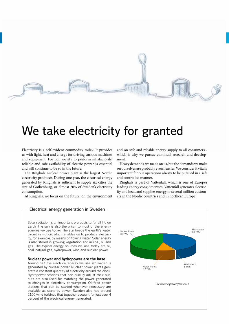
Solar radiation is an important prerequisite for all life on Earth. The sun is also the origin to most of the energy sources we use today. The sun keeps the earth’s water circuit in motion, which enables us to produce electric-ity, for example, by means of flowing water. Solar energy is also stored in growing vegetation and in coal, oil and gas. The typical energy sources we use today are oil, coal, natural gas, hydropower, wind and nuclear power.
Nuclear power and hydropower are the baseAround half the electrical energy we use in Sweden is generated by nuclear power. Nuclear power plants gen-erate a constant quantity of electricity around the clock. Hydropower stations that can quickly adjust their out-puts are also used for matching the power generated to changes in electricity consumption. Oil-fired power stations that can be started whenever necessary are available as stand-by power. Sweden also has around 2100 wind turbines that together account for just over 4 percent of the electrical energy generated.
We take electricity for granted
The electric power year 2011
Electrical energy generation in Sweden
Nuclear Power58 TWh
Hydropower66 TWh
Other thermal17 TWh
Wind power6 TWh
4
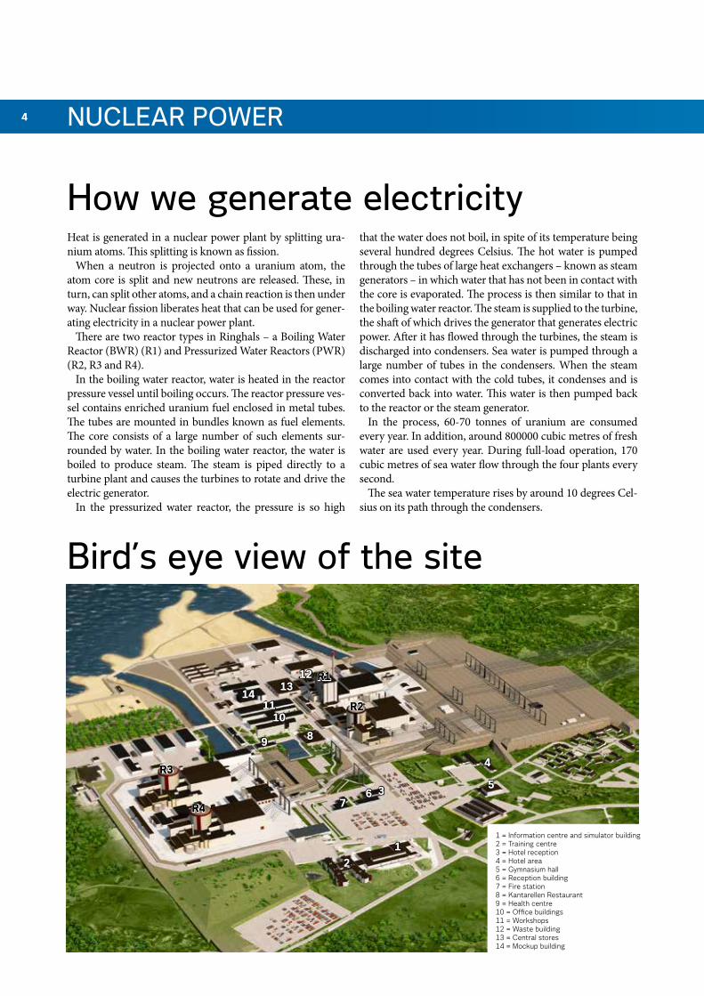
Bird’s eye view of the site
1 = Information centre and simulator building2 = Training centre3 = Hotel reception4 = Hotel area5 = Gymnasium hall6 = Reception building7 = Fire station8 = Kantarellen Restaurant9 = Health centre10 = Office buildings11 = Workshops12 = Waste building13 = Central stores14 = Mockup building
Heat is generated in a nuclear power plant by splitting ura-nium atoms. This splitting is known as fission.
When a neutron is projected onto a uranium atom, the atom core is split and new neutrons are released. These, in turn, can split other atoms, and a chain reaction is then under way. Nuclear fission liberates heat that can be used for gener-ating electricity in a nuclear power plant.
There are two reactor types in Ringhals – a Boiling Water Reactor (BWR) (R1) and Pressurized Water Reactors (PWR) (R2, R3 and R4).
In the boiling water reactor, water is heated in the reactor pressure vessel until boiling occurs. The reactor pressure ves-sel contains enriched uranium fuel enclosed in metal tubes. The tubes are mounted in bundles known as fuel elements. The core consists of a large number of such elements sur-rounded by water. In the boiling water reactor, the water is boiled to produce steam. The steam is piped directly to a turbine plant and causes the turbines to rotate and drive the electric generator.
In the pressurized water reactor, the pressure is so high
that the water does not boil, in spite of its temperature being several hundred degrees Celsius. The hot water is pumped through the tubes of large heat exchangers – known as steam generators – in which water that has not been in contact with the core is evaporated. The process is then similar to that in the boiling water reactor. The steam is supplied to the turbine, the shaft of which drives the generator that generates electric power. After it has flowed through the turbines, the steam is discharged into condensers. Sea water is pumped through a large number of tubes in the condensers. When the steam comes into contact with the cold tubes, it condenses and is converted back into water. This water is then pumped back to the reactor or the steam generator.
In the process, 60-70 tonnes of uranium are consumed every year. In addition, around 800000 cubic metres of fresh water are used every year. During full-load operation, 170 cubic metres of sea water flow through the four plants every second.
The sea water temperature rises by around 10 degrees Cel-sius on its path through the condensers.
How we generate electricity
NuClEar PoWEr
R1
R2
R3
R4
1
3
4
56
7
89
1011
1213
14
2
5
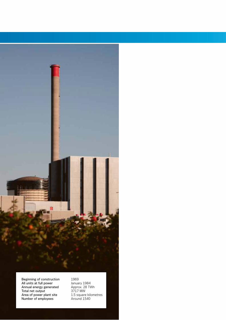
Beginning of construction 1969all units at full power January 1984annual energy generated Approx. 28 TWhTotal net output 3717 MWarea of power plant site 1.5 square kilometres Number of employees Around 1540
6
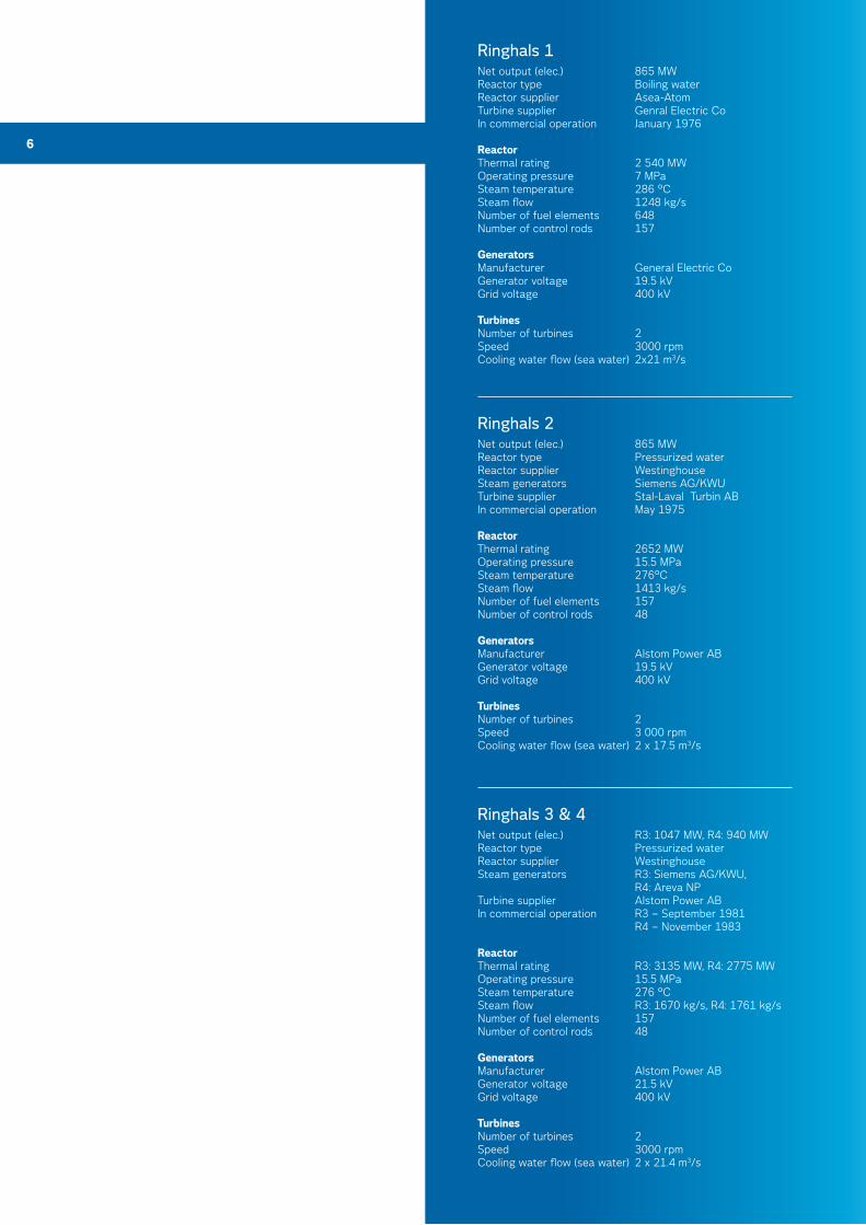
ringhals 1Net output (elec.) 865 MWReactor type Boiling water Reactor supplier Asea-AtomTurbine supplier Genral Electric CoIn commercial operation January 1976
ReactorThermal rating 2 540 MWOperating pressure 7 MPaSteam temperature 286 °CSteam flow 1248 kg/sNumber of fuel elements 648Number of control rods 157
GeneratorsManufacturer General Electric CoGenerator voltage 19.5 kVGrid voltage 400 kV
TurbinesNumber of turbines 2Speed 3000 rpmCooling water flow (sea water) 2x21 m3/s
ringhals 3 & 4 Net output (elec.) R3: 1047 MW, R4: 940 MWReactor type Pressurized waterReactor supplier WestinghouseSteam generators R3: Siemens AG/KWU, R4: Areva NPTurbine supplier Alstom Power ABIn commercial operation R3 – September 1981 R4 – November 1983
ReactorThermal rating R3: 3135 MW, R4: 2775 MWOperating pressure 15.5 MPaSteam temperature 276 °CSteam flow R3: 1670 kg/s, R4: 1761 kg/sNumber of fuel elements 157Number of control rods 48
GeneratorsManufacturer Alstom Power ABGenerator voltage 21.5 kVGrid voltage 400 kV
TurbinesNumber of turbines 2Speed 3000 rpmCooling water flow (sea water) 2 x 21.4 m3/s
ringhals 2Net output (elec.) 865 MWReactor type Pressurized water Reactor supplier WestinghouseSteam generators Siemens AG/KWUTurbine supplier Stal-Laval Turbin ABIn commercial operation May 1975
ReactorThermal rating 2652 MWOperating pressure 15.5 MPaSteam temperature 276°CSteam flow 1413 kg/sNumber of fuel elements 157Number of control rods 48
GeneratorsManufacturer Alstom Power ABGenerator voltage 19.5 kVGrid voltage 400 kV
TurbinesNumber of turbines 2Speed 3 000 rpmCooling water flow (sea water) 2 x 17.5 m3/s
7
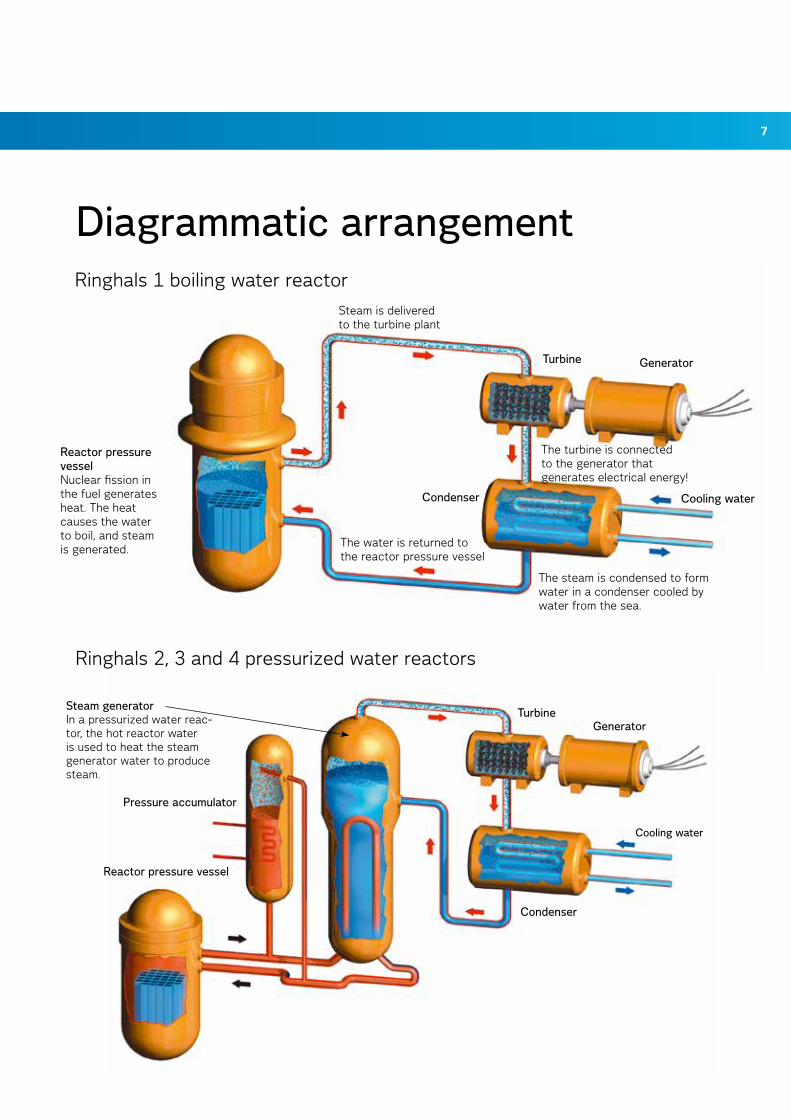
Ringhals 2, 3 and 4 pressurized water reactors
Diagrammatic arrangementRinghals 1 boiling water reactor
Steam is delivered to the turbine plant
The turbine is connected to the generator that generates electrical energy!
The steam is condensed to form water in a condenser cooled by water from the sea.
The water is returned to the reactor pressure vessel
reactor pressure vessel Nuclear fission in the fuel generates heat. The heat causes the water to boil, and steam is generated.
Cooling water
Turbine Generator
Condenser
Steam generator In a pressurized water reac-tor, the hot reactor water is used to heat the steam generator water to produce steam.
reactor pressure vessel
Condenser
TurbineGenerator
Cooling water
Pressure accumulator
8 rEaCTor
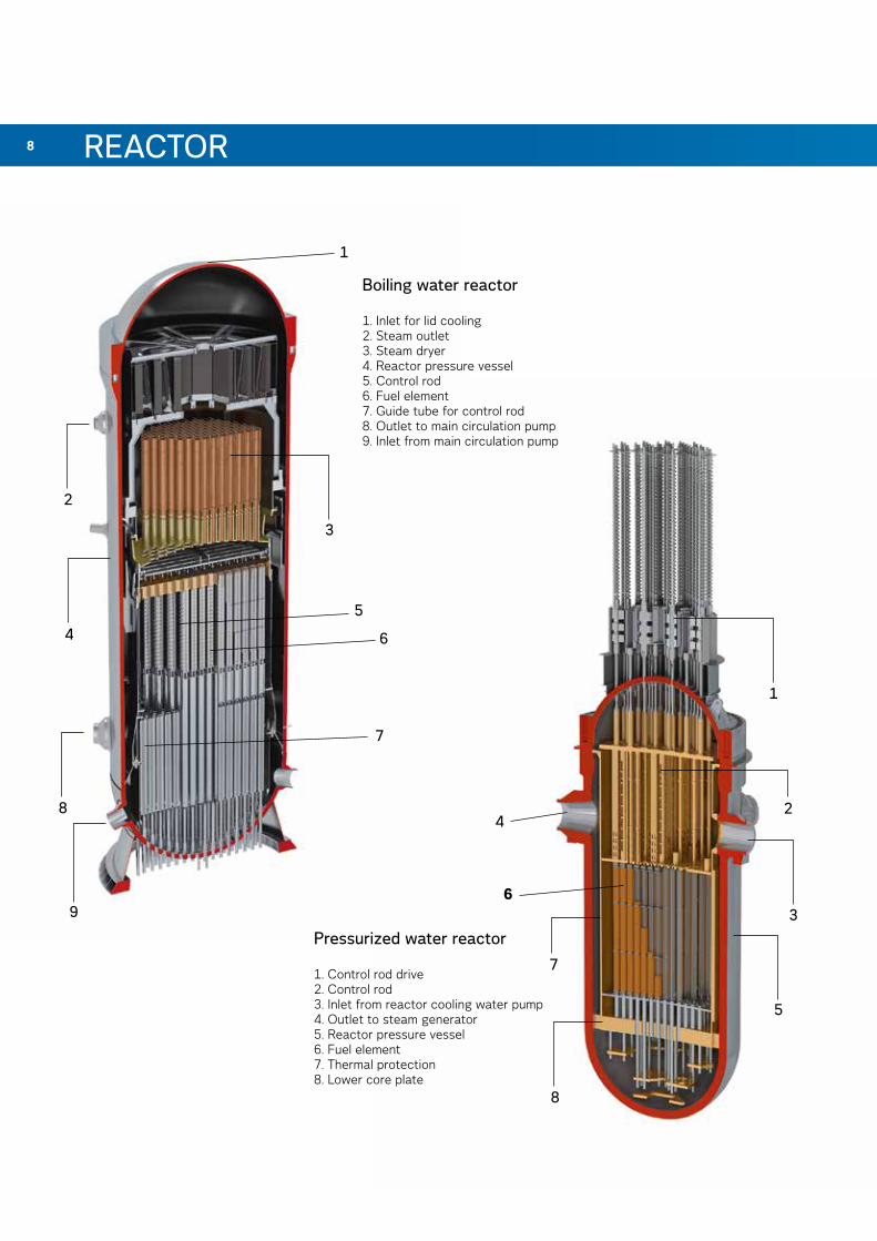
Pressurized water reactor
1. Control rod drive2. Control rod3. Inlet from reactor cooling water pump4. Outlet to steam generator5. Reactor pressure vessel6. Fuel element7. Thermal protection8. Lower core plate
Boiling water reactor
1. Inlet for lid cooling2. Steam outlet3. Steam dryer4. Reactor pressure vessel5. Control rod6. Fuel element7. Guide tube for control rod8. Outlet to main circulation pump9. Inlet from main circulation pump
1
8
2
9
7
5
64
3
1
2
3
4
5
6
8
7
9
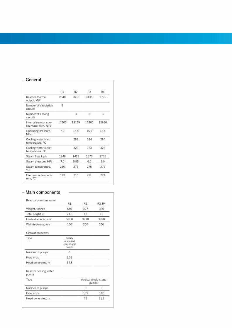
Main components
Reactor pressure vessel R1 R2 R3, R4
Weight, tonnes 650 327 330
Total height, m 21,5 13 13
Inside diameter, mm 5950 3990 3990
Wall thickness, mm 150 200 200
Circulation pumps
Type Totally enclosed
centrifugal pumps
Number of pumps 6
Flow, m3/s 2,53
Head generated, m 34,3
Reactor cooling water pumps
Type Vertical single-stage pumps
Number of pumps 3 3
Flow, m3/s 5,72 5,66
Head generated, m 78 81,2
General
R1 R2 R3 R4
Reactor thermal output, MW
2540 2652 3135 2775
Number of circulation circuits
6
Number of cooling circuits
3 3 3
Internal reactor coo-ling water flow, kg/s
11500 13159 12860 12860
Operating pressure, MPa
7,0 15,5 15,5 15,5
Cooling water inlet temperature, °C
289 284 284
Cooling water outlet temperature, °C
323 323 323
Steam flow, kg/s 1248 1413 1670 1761
Steam pressure, MPa 7,0 5,95 6,0 6,0
Steam temperature, °C
286 276 276 276
Feed water tempera-ture, °C
173 210 221 221
10
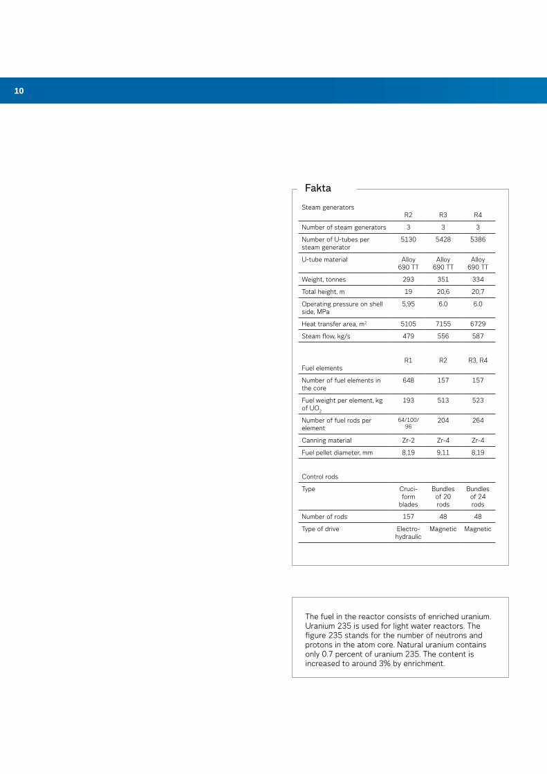
Fakta
Steam generators R2
R3
R4
Number of steam generators 3 3 3
Number of U-tubes per steam generator
5130 5428 5386
U-tube material Alloy 690 TT
Alloy 690 TT
Alloy 690 TT
Weight, tonnes 293 351 334
Total height, m 19 20,6 20,7
Operating pressure on shell side, MPa
5,95 6.0 6.0
Heat transfer area, m2 5105 7155 6729
Steam flow, kg/s 479 556 587
Fuel elements
R1
R2
R3, R4
Number of fuel elements in the core
648 157 157
Fuel weight per element, kg of UO2
193 513 523
Number of fuel rods per element
64/100/ 96
204 264
Canning material Zr-2 Zr-4 Zr-4
Fuel pellet diameter, mm 8,19 9,11 8,19
Control rods
Type Cruci-form
blades
Bundles of 20 rods
Bundles of 24 rods
Number of rods 157 48 48
Type of drive Electro-hydraulic
Magnetic Magnetic
The fuel in the reactor consists of enriched uranium. Uranium 235 is used for light water reactors. The figure 235 stands for the number of neutrons and protons in the atom core. Natural uranium contains only 0.7 percent of uranium 235. The content is increased to around 3% by enrichment.
11
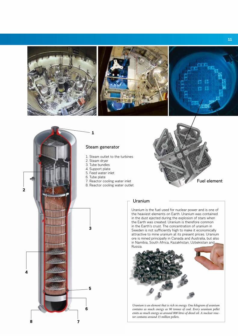
Uranium is the fuel used for nuclear power and is one of the heaviest elements on Earth. Uranium was contained in the dust ejected during the explosion of stars when the Earth was created. Uranium is therefore common in the Earth’s crust. The concentration of uranium in Sweden is not sufficiently high to make it economically attractive to mine uranium at its present prices. Uranium ore is mined principally in Canada and Australia, but also in Namibia, South Africa, Kazakhstan, Uzbekistan and Russia.
uranium
Uranium is an element that is rich in energy. One kilogram of uranium contains as much energy as 90 tonnes of coal. Every uranium pellet emits as much energy as around 800 litres of diesel oil. A nuclear reac-tor contains around 15 million pellets.
Steam generator
1. Steam outlet to the turbines2. Steam dryer3. Tube bundles4. Support plate5. Feed water inlet6. Tube plate7. Reactor cooling water inlet8. Reactor cooling water outlet
Fuel element
1
8
2
7
5
6
4
3
12
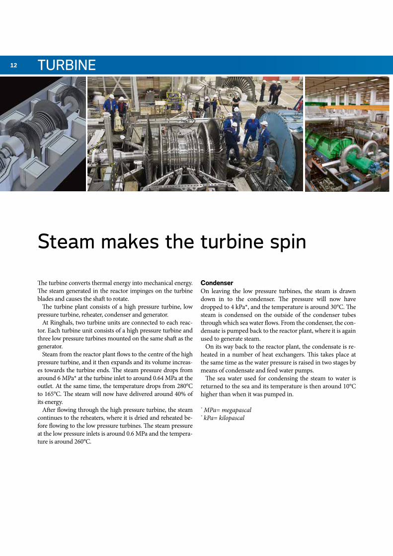
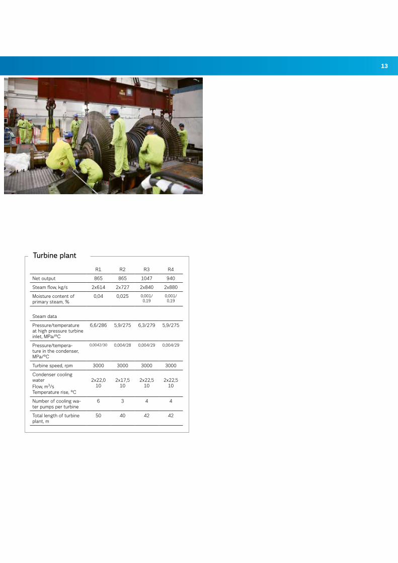
Steam makes the turbine spin
TurBiNE
The turbine converts thermal energy into mechanical energy. The steam generated in the reactor impinges on the turbine blades and causes the shaft to rotate.
The turbine plant consists of a high pressure turbine, low pressure turbine, reheater, condenser and generator.
At Ringhals, two turbine units are connected to each reac-tor. Each turbine unit consists of a high pressure turbine and three low pressure turbines mounted on the same shaft as the generator.
Steam from the reactor plant flows to the centre of the high pressure turbine, and it then expands and its volume increas-es towards the turbine ends. The steam pressure drops from around 6 MPa* at the turbine inlet to around 0.64 MPa at the outlet. At the same time, the temperature drops from 280°C to 165°C. The steam will now have delivered around 40% of its energy.
After flowing through the high pressure turbine, the steam continues to the reheaters, where it is dried and reheated be-fore flowing to the low pressure turbines. The steam pressure at the low pressure inlets is around 0.6 MPa and the tempera-ture is around 260°C.
CondenserOn leaving the low pressure turbines, the steam is drawn down in to the condenser. The pressure will now have dropped to 4 kPa*, and the temperature is around 30°C. The steam is condensed on the outside of the condenser tubes through which sea water flows. From the condenser, the con-densate is pumped back to the reactor plant, where it is again used to generate steam.
On its way back to the reactor plant, the condensate is re-heated in a number of heat exchangers. This takes place at the same time as the water pressure is raised in two stages by means of condensate and feed water pumps.
The sea water used for condensing the steam to water is returned to the sea and its temperature is then around 10°C higher than when it was pumped in.
* MPa= megapascal* kPa= kilopascal
13
Turbine plant
R1 R2 R3 R4
Net output 865 865 1047 940
Steam flow, kg/s 2x614 2x727 2x840 2x880
Moisture content of primary steam, %
0,04 0,025 0,001/ 0,19
0,001/ 0,19
Steam data
Pressure/temperature at high pressure turbine inlet, MPa/°C
6,6/286 5,9/275 6,3/279 5,9/275
Pressure/tempera-ture in the condenser, MPa/°C
0,0042/30 0,004/28 0,004/29 0,004/29
Turbine speed, rpm 3000 3000 3000 3000
Condenser cooling waterFlow, m3/s Temperature rise, °C
2x22,010
2x17,510
2x22,510
2x22,510
Number of cooling wa-ter pumps per turbine
6 3 4 4
Total length of turbine plant, m
50 40 42 42
14 ElECTriCiTY
Electrical equipment
R1 R2 R3, R4
Generator
Manufacturer GEC Alstom Power
Alstom Power
Number of generators 2 2 2
Rated voltage, kV 19,5 19,5 21,5
Rated output, MVA 470 540 677
Power factor 0,95 0,85 0,9
Stator cooling Water/ hydrogen
Water/air Water/air
Rotor cooling Hydrogen Water Water
Main transformers
Number of transformers 2 2 2
Rated voltage, kV 20,5/438 20,5/438 22,6/438,5
Rating, MVA 500 500 550,650
Local transformers
Number of transformers 2 2 2
Rated voltage, kV 19,5/6,8 19,5/6,8 19,5/6,8
Rating, MVA 40/25 40/25 50/25
Diesel generators
Number of diesel gene-rators
4 4 4
Engine manufacturer SACM SACM NOHAB
Diesel generator, manu-facturer
ASEA ASEA ASEA
Rated voltage, kV 6,9 6,9 6,9
Rating, MVA 3,42 3,42 3,45
Power factor 0,8 0,8 0,8
Speed, rpm 1500 1500 1000
15
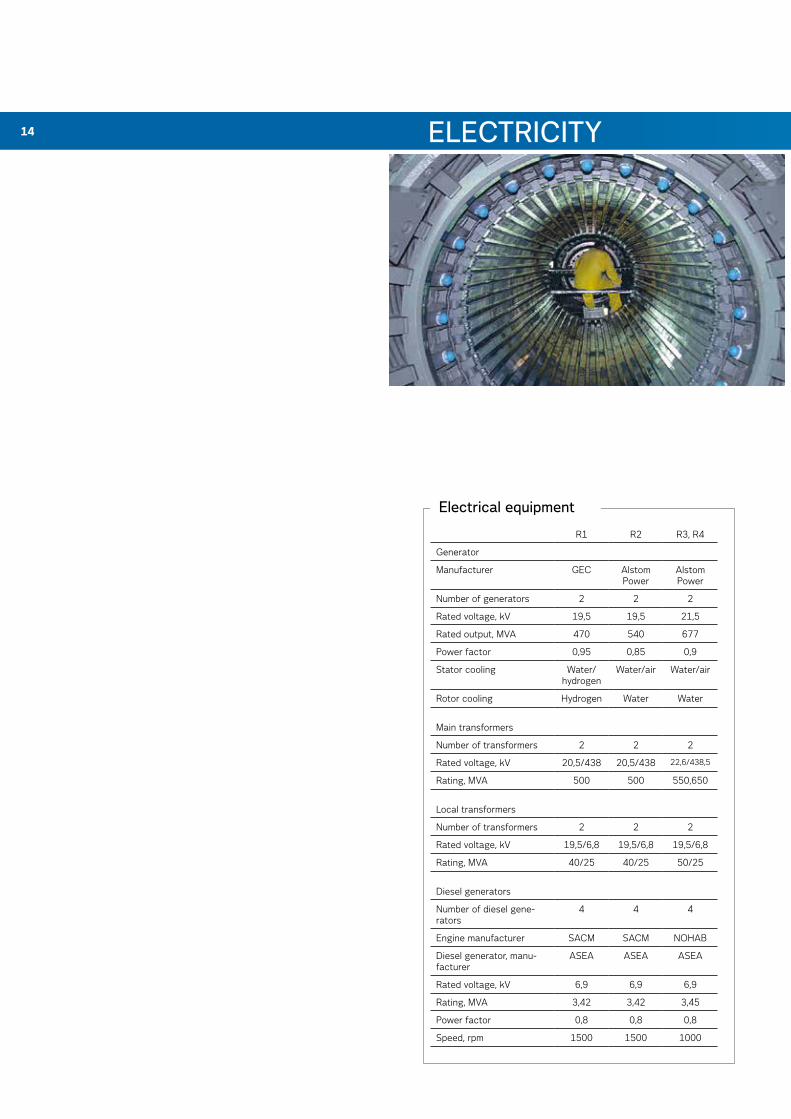
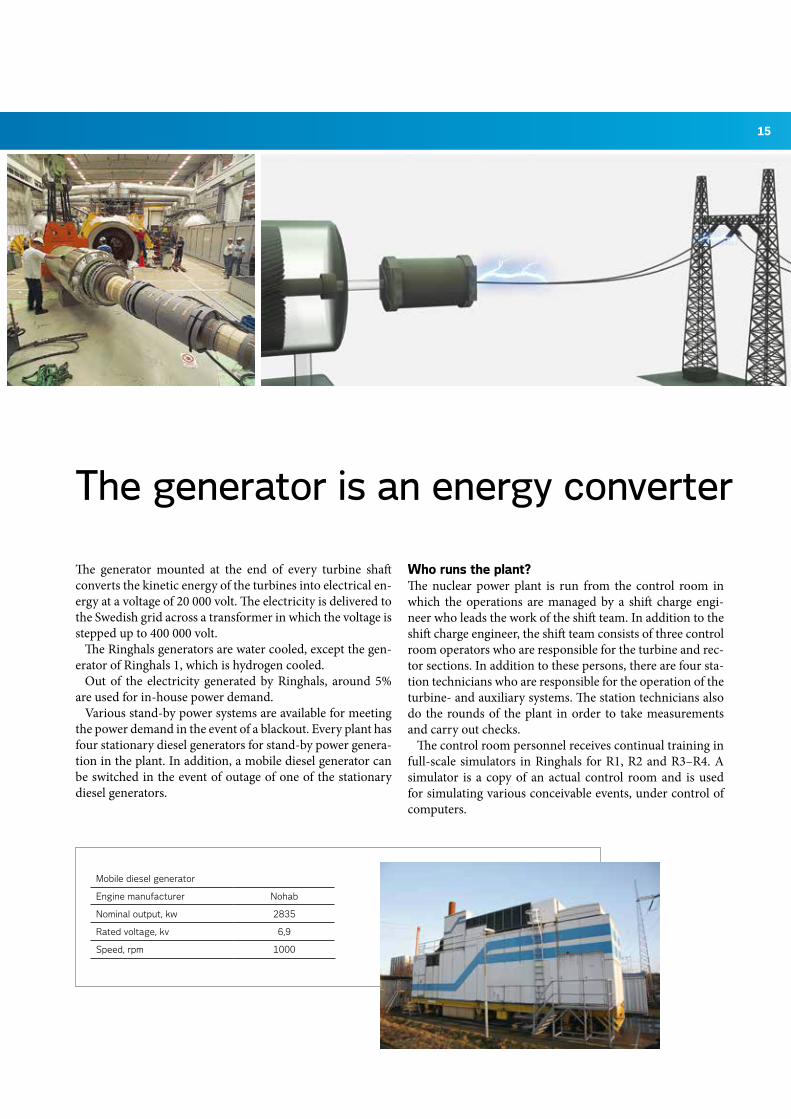
The generator is an energy converter
ElECTriCiTY
The generator mounted at the end of every turbine shaft converts the kinetic energy of the turbines into electrical en-ergy at a voltage of 20 000 volt. The electricity is delivered to the Swedish grid across a transformer in which the voltage is stepped up to 400 000 volt.
The Ringhals generators are water cooled, except the gen-erator of Ringhals 1, which is hydrogen cooled.
Out of the electricity generated by Ringhals, around 5% are used for in-house power demand.
Various stand-by power systems are available for meeting the power demand in the event of a blackout. Every plant has four stationary diesel generators for stand-by power genera-tion in the plant. In addition, a mobile diesel generator can be switched in the event of outage of one of the stationary diesel generators.
Who runs the plant?The nuclear power plant is run from the control room in which the operations are managed by a shift charge engi-neer who leads the work of the shift team. In addition to the shift charge engineer, the shift team consists of three control room operators who are responsible for the turbine and rec-tor sections. In addition to these persons, there are four sta-tion technicians who are responsible for the operation of the turbine- and auxiliary systems. The station technicians also do the rounds of the plant in order to take measurements and carry out checks.
The control room personnel receives continual training in full-scale simulators in Ringhals for R1, R2 and R3–R4. A simulator is a copy of an actual control room and is used for simulating various conceivable events, under control of computers.
Mobile diesel generator
Engine manufacturer Nohab
Nominal output, kw 2835
Rated voltage, kv 6,9
Speed, rpm 1000
16
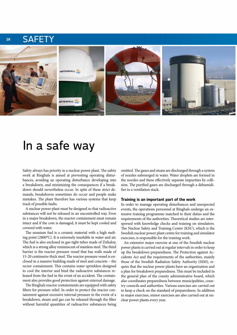
in a safe way
SaFETY
Safety always has priority in a nuclear power plant. The safety work at Ringhals is aimed at preventing operating distur-bances, avoiding an operating disturbance developing into a breakdown, and minimizing the consequences if a break-down should nevertheless occur. In spite of these strict de-mands, breakdowns sometimes do occur and people make mistakes. The plant therefore has various systems that keep track of possible faults.
A nuclear power plant must be designed so that radioactive substances will not be released in an uncontrolled way. Even in a major breakdown, the reactor containment must remain intact and if the core is damaged, it must be kept cooled and covered with water.
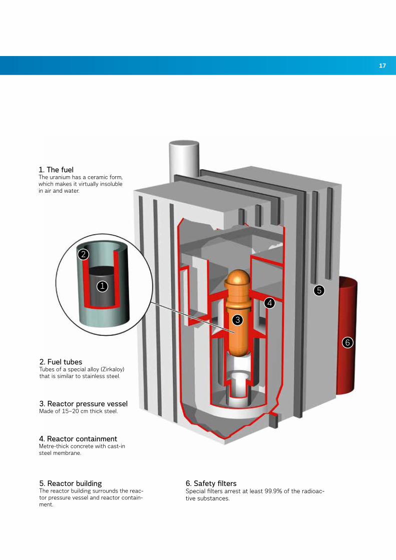
The uranium fuel is a ceramic material with a high melt-ing point (2800°C). It is extremely insoluble in water and air. The fuel is also enclosed in gas-tight tubes made of Zirkaloy, which is a strong alloy reminiscent of stainless steel. The third barrier is the reactor pressure vessel that has walls made of 15-20 centimetre thick steel. The reactor pressure vessel is en-closed in a massive building made of steel and concrete – the rector containment. This contains water sprinklers designed to cool the interior and bind the radioactive substances re-leased from the fuel in the event of an accident. The contain-ment also provides good protection against external damage.
The Ringhals reactor containments are equipped with safety filters for pressure relief. In order to protect the reactor con-tainment against excessive internal pressure in the event of a breakdown, steam and gas can be released through the filter without harmful quantities of radioactive substances being
emitted. The gases and steam are discharged through a system of nozzles submerged in water. Water droplets are formed in the nozzles and these effectively separate impurities by colli-sion. The purified gases are discharged through a dehumidi-fier to a ventilation stack.
Training is an important part of the workIn order to manage operating disturbances and unexpected events, the operations personnel at Ringhals undergo an ex-tensive training programme matched to their duties and the requirements of the authorities. Theoretical studies are inter-spersed with knowledge checks and training on simulators. The Nuclear Safety and Training Centre (KSU), which is the Swedish nuclear power plant centre for training and simulator exercises, is responsible for the training work.
An extensive major exercise at one of the Swedish nuclear power plants is carried out at regular intervals in order to keep up the breakdown preparedness. The Protection against Ac-cidents Act and the requirements of the authorities, mainly those of the Swedish Radiation Safety Authority (SSM), re-quire that the nuclear power plants have an organization and a plan for breakdown preparedness. This must be included in the general plan of the county administrative board, which also coordinates preparedness between municipalities, coun-try councils and authorities. Various exercises are carried out to keep a check on the standard of preparedness. In addition to major exercises, minor exercises are also carried out at nu-clear power plants every year.
17
11
12
13
14
15
16
1. The fuelThe uranium has a ceramic form, which makes it virtually insoluble in air and water.
2. Fuel tubesTubes of a special alloy (Zirkaloy) that is similar to stainless steel.
3. reactor pressure vesselMade of 15–20 cm thick steel.
4. reactor containmentMetre-thick concrete with cast-in steel membrane.
6. Safety filtersSpecial filters arrest at least 99.9% of the radioac-tive substances.
5. reactor buildingThe reactor building surrounds the reac-tor pressure vessel and reactor contain-ment.
18
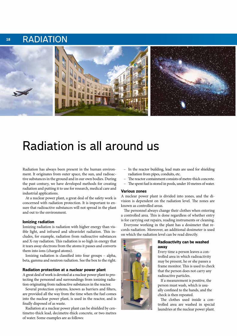
Radiation has always been present in the human environ-ment. It originates from outer space, the sun, and radioac-tive substances in the ground and in our own bodies. During the past century, we have developed methods for creating radiation and putting it to use for research, medical care and industrial applications.
At a nuclear power plant, a great deal of the safety work is concerned with radiation protection. It is important to en-sure that radioactive substances will not spread in the plant and out to the environment.
Ionizing radiation Ionizing radiation is radiation with higher energy than vis-ible light, and infrared and ultraviolet radiation. This in-cludes, for example, radiation from radioactive substances and X-ray radiation. This radiation is so high in energy that it tears away electrons from the atoms it passes and converts them into ions (charged atoms).
Ionizing radiation is classified into four groups – alpha, beta, gamma and neutron radiation. See the box to the right.
Radiation protection at a nuclear power plantA great deal of work is devoted at a nuclear power plant to pro-tecting the personnel and surroundings from ionizing radia-tion originating from radioactive substances in the reactor.
Several protection systems, known as barriers and filters, are provided all the way from the time when the fuel comes into the nuclear power plant, is used in the reactor, and is finally disposed of as waste.
Radiation at a nuclear power plant can be shielded by cen-timetre-thick lead, decimetre-thick concrete, or two metres of water. Some examples are as follows:
– In the reactor building, lead mats are used for shielding radiation from pipes, conduits, etc.
– The reactor containment consists of metre-thick concrete. – The spent fuel is stored in pools, under 10 metres of water.
Various zonesA nuclear power plant is divided into zones, and the di-vision is dependent on the radiation level. The zones are known as controlled areas.
The personnel always change their clothes when entering a controlled area. This is done regardless of whether entry is for carrying out repairs, reading instruments or cleaning.
Everyone working in the plant has a dosimeter that re-cords radiation. Moreover, an additional dosimeter is used on which the radiation level can be read directly.
Radioactivity can be washed awayEvery time a person leaves a con-trolled area in which radioactivity may be present, he or she passes a frame monitor. This is used to check that the person does not carry any radioactive particles.
If a measurement is positive, the person must wash, which is usu-ally confined to the hands, and the check is then repeated.
The clothes used inside a con-trolled area are washed in special laundries at the nuclear power plant.
radiation is all around us
raDiaTioN
19
radiation doses per year
Emissions from Ringhals (immediate neighbours)
0.0003 mSv or 0.5% of the permissible limit value (2011)
Radioactive substances in our own bodies
0,2 mSv
Nuclear power worker(in a radiation environment)
2-3 mSv
Air hostess 5 mSv
Action level for radon house
8 mSv
Radiation doses are measured in millisieverts, mSv. Every Swede is subjected to an average of 4 mSv from natural background radiation, radiation in dwellings and medi-cal interventions. For work with ionizing radiation, the Swedish Radiation Safety Authority (SSM) has set an upper limit – 50 mSv during one year and a total of 100 mSv over a 5-year period. The average dose in Swed-ish nuclear power plants is around 3 mSv. The collective dose is measured in man-sievert, man-Sv. The collective dose for a plant corresponds to the total of all radiation doses measured at the plant during one year.
radiation doses
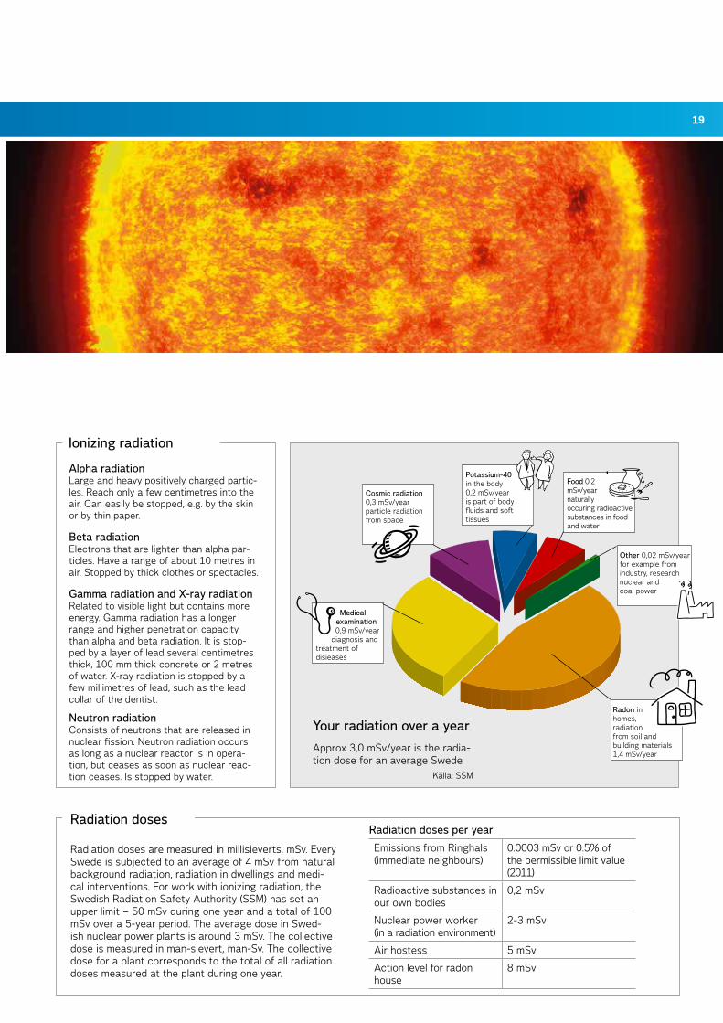
alpha radiation Large and heavy positively charged partic-les. Reach only a few centimetres into the air. Can easily be stopped, e.g. by the skin or by thin paper.
Beta radiationElectrons that are lighter than alpha par-ticles. Have a range of about 10 metres in air. Stopped by thick clothes or spectacles.
Gamma radiation and X-ray radiation Related to visible light but contains more energy. Gamma radiation has a longer range and higher penetration capacity than alpha and beta radiation. It is stop-ped by a layer of lead several centimetres thick, 100 mm thick concrete or 2 metres of water. X-ray radiation is stopped by a few millimetres of lead, such as the lead collar of the dentist.
Neutron radiationConsists of neutrons that are released in nuclear fission. Neutron radiation occurs as long as a nuclear reactor is in opera-tion, but ceases as soon as nuclear reac-tion ceases. Is stopped by water.
ionizing radiation
Källa: SSM
Radon in homes, radiation from soil and building materials 1,4 mSv/year
Medical examination 0,9 mSv/year
diagnosis and treatment of disieases
Cosmic radiation 0,3 mSv/yearparticle radiation from space
Potassium-40 in the body 0,2 mSv/yearis part of body fluids and soft tissues
Food 0,2 mSv/yearnaturally occuring radioactive substances in food and water
Other 0,02 mSv/yearfor example from industry, research nuclear and coal power
Your radiation over a year
Approx 3,0 mSv/year is the radia-tion dose for an average Swede

20
At Ringhals, we work continually towards reducing the en-vironmental impact of our operations. This applies to fields such as dangerous waste, chemicals, ordinary waste, water treatment, cooling water discharge, and emissions of ra-dioactive substances. Our aim is to limit the quantities and to reuse or recover as much material as possible.
Our work on environmental issues is important for crea-ting a good environment and meeting the demands made on us. Ringhals has been registered in the Eco Management and Audit Scheme (Emas) since 1999, and has been certified to ISO 14001 since 1998. A certificate offers proof that we meet a number of requirements made on our internal environme-ntal work. Our environmental management system is part of our quality system. Electricity from Ringhals has Environ-mental Product Declaration (EPD), which means that the environmental impact of everything from uranium mining to terminal storage is defined. For further information on EPD, visit www.vattenfall.com.
Environmental targets at RinghalsRinghals takes decisions annually on the environmental tar-gets for the coming year, as an element in guiding the ope-rations. The environmental targets are classified into four areas. In-house environment that includes matters such as radiation doses to the employees. Outdoor environment that includes matters such as waste management. Emissions of radioactive substances to the atmosphere and water. Or-ganizational matters that cover relations with the authori-ties, and improvement work.
As regards the target for a safe radiation environment, for example, the emissions from Ringhals to the atmosphere and water recipients conform to the requirements of the authorities with a very comfortable margin. The emissions
from Ringhals to the immediate neighbours are far below the specified limit values and are equivalent to less than one thousandth of the dose from natural radiation sources.
Inspection programmeThe environmental impact of Ringhals is regularly check-ed by biological recipient checks by the National Board of Fisheries, by the inspection programme of the County Ad-ministrative Board, and by the radiological measurement programme of SSM. The inspection programme is based on our taking samples, analyzing them and reporting the results to the authorities by environmental reports and en-vironmental inspections.
The radiological environmental inspection programme covers the collection of samples on land and in the water around Ringhals. Samples are taken of vegetation, animal products, sediment, algae, molluscs and fish. The test results are checked by SSM.
Focus on the environment
THE ENviroNMENT
Ringhals is the first nuclear power plant to have com-missioned environmental testing of the whole of the operations. Environmental testing is a very good way of gaining a complete picture of the environmental impact of the entire operations in order to be able to continue the environmental improvement work.
The court judgement obtained in the spring of 2006 makes a number of requirements on our operations, in addition to those we have already received, on how Ringhals could improve its environmental work. One of the requirements was that Ringhals should reduce the noise caused by the operations.
You can find out more about our environmental testing by visiting our home page at www.vattenfall.com/ringhals.
Environmentally tested operations
21
22
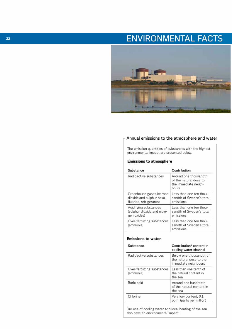
annual emissions to the atmosphere and water
ENviroNMENTal FaCTS
Substance Contribution
Radioactive substances Around one thousandth of the natural dose to the immediate neigh-bours
Greenhouse gases (carbon dioxide,and sulphur hexa-fluoride, refrigerants)
Less than one ten thou-sandth of Sweden’s total emissions
Acidifying substances (sulphur dioxide and nitro-gen oxides)
Less than one ten thou-sandth of Sweden’s total emissions
Over-fertilizing substances (ammonia)
Less than one ten thou-sandth of Sweden’s total emissions
The emission quantities of substances with the highest environmental impact are presented below.
Our use of cooling water and local heating of the sea also have an environmental impact.
Emissions to atmosphere
Substance Contribution/ content in cooling water channel
Radioactive substances Below one thousandth of the natural dose to the immediate neighbours
Over-fertilizing substances(ammonia)
Less than one tenth of the natural content in the sea
Boric acid Around one hundredth of the natural content in the sea
Chlorine Very low content, 0.1 ppm (parts per million)
Emissions to water
ENviroNMENTal FaCTS
24
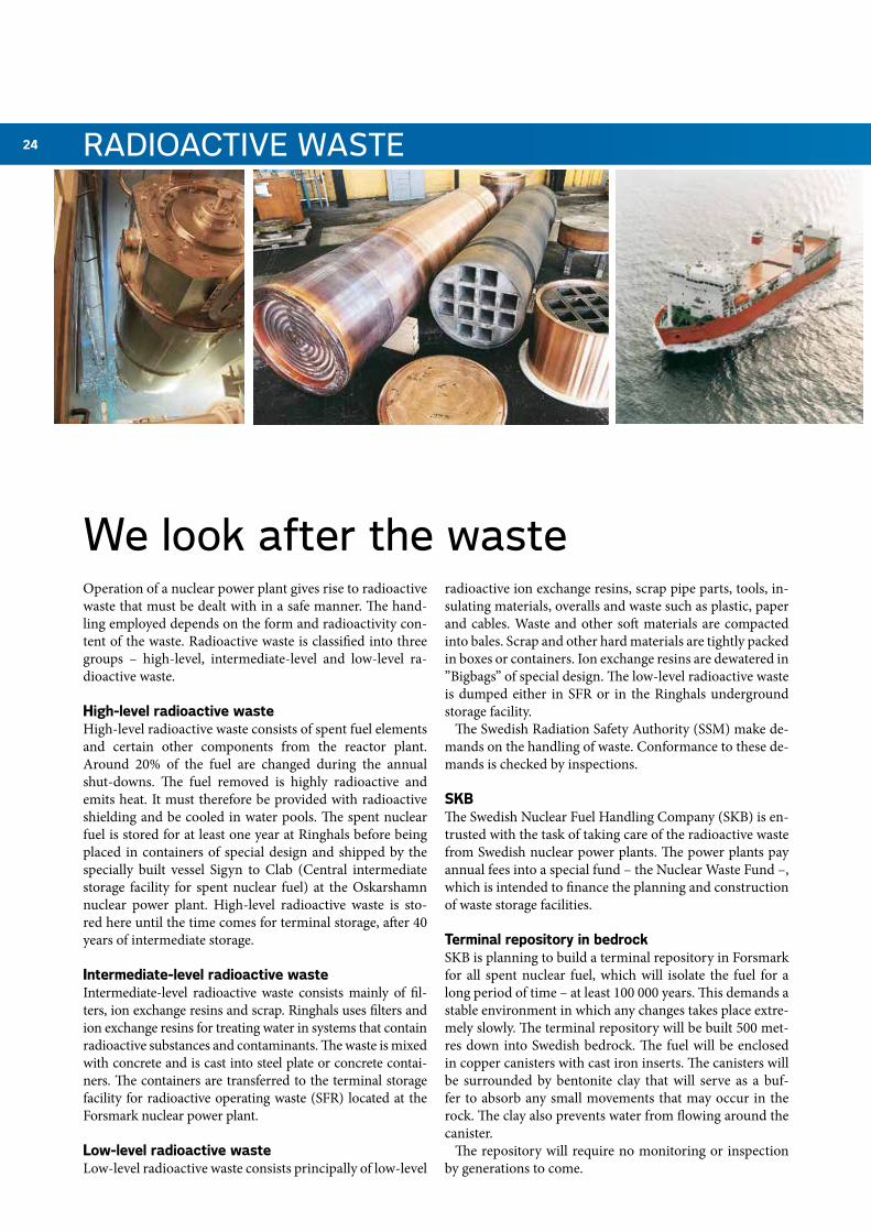
We look after the waste
raDioaCTivE WaSTE
Operation of a nuclear power plant gives rise to radioactive waste that must be dealt with in a safe manner. The hand-ling employed depends on the form and radioactivity con-tent of the waste. Radioactive waste is classified into three groups – high-level, intermediate-level and low-level ra-dioactive waste.
High-level radioactive wasteHigh-level radioactive waste consists of spent fuel elements and certain other components from the reactor plant. Around 20% of the fuel are changed during the annual shut-downs. The fuel removed is highly radioactive and emits heat. It must therefore be provided with radioactive shielding and be cooled in water pools. The spent nuclear fuel is stored for at least one year at Ringhals before being placed in containers of special design and shipped by the specially built vessel Sigyn to Clab (Central intermediate storage facility for spent nuclear fuel) at the Oskarshamn nuclear power plant. High-level radioactive waste is sto-red here until the time comes for terminal storage, after 40 years of intermediate storage.
Intermediate-level radioactive wasteIntermediate-level radioactive waste consists mainly of fil-ters, ion exchange resins and scrap. Ringhals uses filters and ion exchange resins for treating water in systems that contain radioactive substances and contaminants. The waste is mixed with concrete and is cast into steel plate or concrete contai-ners. The containers are transferred to the terminal storage facility for radioactive operating waste (SFR) located at the Forsmark nuclear power plant.
Low-level radioactive wasteLow-level radioactive waste consists principally of low-level
radioactive ion exchange resins, scrap pipe parts, tools, in-sulating materials, overalls and waste such as plastic, paper and cables. Waste and other soft materials are compacted into bales. Scrap and other hard materials are tightly packed in boxes or containers. Ion exchange resins are dewatered in ”Bigbags” of special design. The low-level radioactive waste is dumped either in SFR or in the Ringhals underground storage facility.
The Swedish Radiation Safety Authority (SSM) make de-mands on the handling of waste. Conformance to these de-mands is checked by inspections.
SKBThe Swedish Nuclear Fuel Handling Company (SKB) is en-trusted with the task of taking care of the radioactive waste from Swedish nuclear power plants. The power plants pay annual fees into a special fund – the Nuclear Waste Fund –, which is intended to finance the planning and construction of waste storage facilities.
Terminal repository in bedrockSKB is planning to build a terminal repository in Forsmark for all spent nuclear fuel, which will isolate the fuel for a long period of time – at least 100 000 years. This demands a stable environment in which any changes takes place extre-mely slowly. The terminal repository will be built 500 met-res down into Swedish bedrock. The fuel will be enclosed in copper canisters with cast iron inserts. The canisters will be surrounded by bentonite clay that will serve as a buf-fer to absorb any small movements that may occur in the rock. The clay also prevents water from flowing around the canister.
The repository will require no monitoring or inspection by generations to come.
25
2006
2007
2008
2009
2010
2011
2012
2013
2014
2015
2016
2017
2018
2019
2020
2021
2022
2023
2024
2025
2026
2027
m/s Sigyn
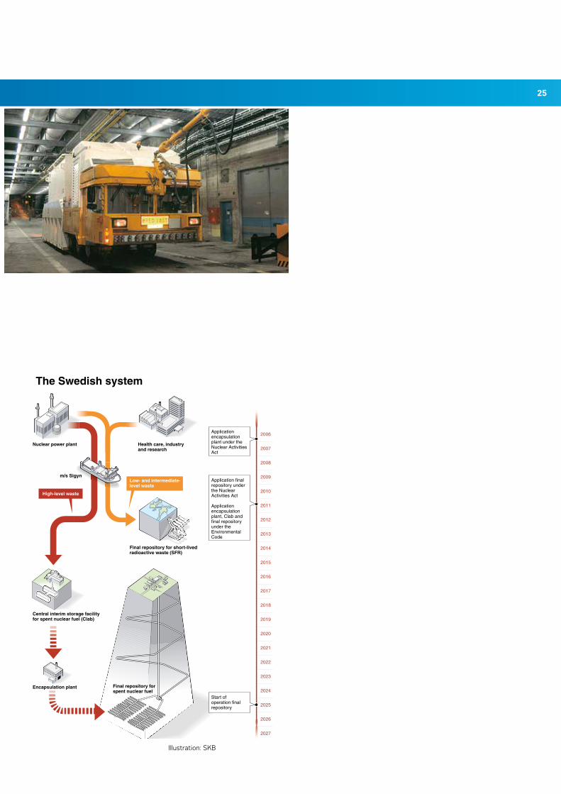
The Swedish system
Nuclear power plant Health care, industryand research
Final repository for short-livedradioactive waste (SFR)
Central interim storage facility for spent nuclear fuel (Clab)
Encapsulation plant Final repository for spent nuclear fuel
Low- and intermediate- level waste
High-level waste
Application encapsulation plant under the Nuclear Activities Act
Application final repository under the Nuclear Activities Act
Applicationencapsulation plant, Clab and final repository under the Environmental Code
Start of operation final repository
Illustration: SKB
26
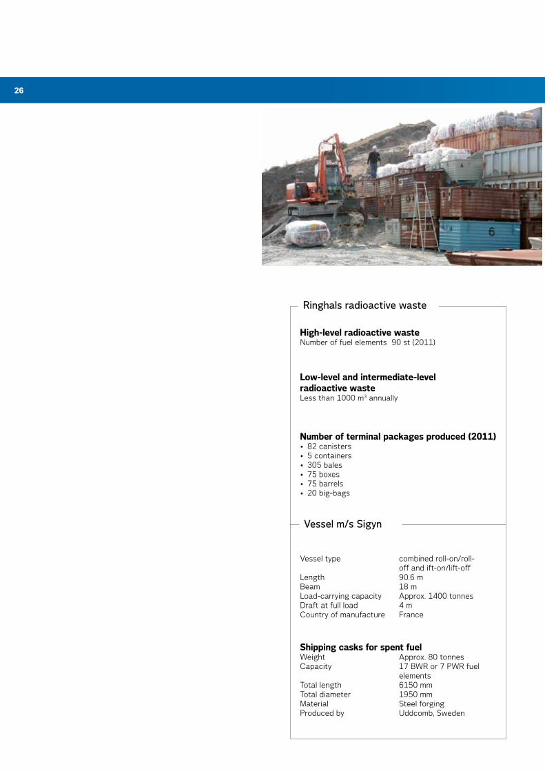
ringhals radioactive waste
Low-level and intermediate-level radioactive wasteLess than 1000 m3 annually
Number of terminal packages produced (2011)• 82 canisters• 5 containers• 305 bales• 75 boxes• 75 barrels• 20 big-bags
High-level radioactive wasteNumber of fuel elements 90 st (2011)
Vessel type combined roll-on/roll- off and ift-on/lift-offLength 90.6 mBeam 18 mLoad-carrying capacity Approx. 1400 tonnesDraft at full load 4 mCountry of manufacture France
Shipping casks for spent fuelWeight Approx. 80 tonnesCapacity 17 BWR or 7 PWR fuel elementsTotal length 6150 mmTotal diameter 1950 mmMaterial Steel forgingProduced by Uddcomb, Sweden
vessel m/s Sigyn
27
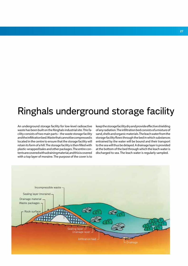
ringhals underground storage facilityAn underground storage facility for low-level radioactive waste has been built on the Ringhals industrial site. This fa-cility consists of two main parts – the waste storage facility and the infiltration bed. Waste that cannot be compressed is located in the centre to ensure that the storage facility will retain its form of a hill. The storage facility is then filled with plastic-wrapped bales and other packages. The entire con-tents are covered with a draining material, and this is covered with a top layer of moraine. The purpose of the cover is to
keep the storage facility dry and provide effective shielding of any radiation. The infiltration bed consists of a mixture of sand, shells and organic materials. The leach water from the storage facility flows through the bed in which substances entrained by the water will be bound and their transport to the sea will thus be delayed. A drainage layer is provided at the bottom of the bed through which the leach water is discharged to sea. The leach water is regularly sampled.
Incompressible waste
Sealing layer (moraine)
Drainage material
Waste packages
Rock surface
Sealing layerDrainage layer
Infiltration bedDrainage
28 GloSSarY oF TErMS
Fuel pellet: Small cylindrical piece of compressed and sin-tered (fused) uranium dioxide included in the reactor core.
Clab: Central intermediate storage facility for spent nuclear fuel. The Clab is located at the Oskarshamn nuclear power plant.
Decontamination: In radiation protection and nuclear technology, denotes the removal of dirt containing ra-dioactive substances. Contamination is the opposite.
Repository: Place where waste is dumped. Rubbish dump in daily parlance.
Dosimeter: Instrument that measures the radiation dose to which a person is subjected.
Eco Management and Audit Scheme: Abbreviated to Emas. The voluntary EU environmental management and environmental auditing ordinance – regulations for com-panies to guide their environmental work.
Environmental Product Declaration (EPD): This declara-tion specifies the magnitude of the environmental impact caused by every unit produced. The EPD shows every conceivable environmental impact from uranium mining to terminal storage of the waste.
Exemption: Material that has been in an area in which the-re are radioactive substances (controlled area) and that, after special measurement, has proved to have such low radiation level that it can be handled without restrictions from the radiation protection aspect.
Half life: The time it takes for half of the radioactive atoms to decay. Every radioactive substance has a specific half life (the radiation is halved).
ISO 14001: International standard for management sys-tems of companies. ISO 14001 is the standard for envi-ronmental management. Conformance to a certain stan-dard means that the relevant company can maintain at least the level specified in the standard.
Ionizing radiation: Radiation that contains so much ener-gy that it can ionize materials. This radiation can damage human cells.
Collective dose: Total radiation dose to a group that has been subjected to ionizing radiation. Expressed in man-sievert, man-Sv.
Millisievert: mSv – measure of the radiation dose to a hu-man being. 1 mSv is the background radiation during 1 year.
Noble gas: Noble gases are a group of gaseous elements that, due to their structure, are not included in any chemi-cal compounds.
Radioactivity: Certain substances are unstable and emit ionizing radiation when they decay. The decay is measu-red in Becquerel, Bq. 1 Bq = 1 nucleus decay per second.
SFR: Terminal storage facility for radioactive operating waste. Located at the Forsmark nuclear power plant. Ope-rating waste includes spare parts that have been irradia-ted, as well as protective clothing, tools, packaging, mea-suring instruments and filters.
Sigyn: Special vessel for transporting spent nuclear fuel and other radioactive waste.
SKB: The Swedish Nuclear Fuel Handling Company, which develops methods for and takes care of our radioactive waste. SKB is owned jointly by the nuclear power plants.
SSM: The Swedish Radiation Safety Authority has been a managing authority under the Ministry of the Environment since 1 July 2008, with national collective responsibility within the areas of radiation protection and nuclear safety (Former SSI – Swedish Radiation Protection and SKI - The Swedish Nuclear Power Inspectorate merged in 2008 to SSM - Swedish Radiation Safety Authority).
Radiation dose: Ionizing radiation that may have an effect on the irradiated cells. The amount of radiation per unit of weight is known as the radiation dose.
Radiation: Energy in motion, e.g. light. A distinction is made between ionizing and non-ionizing radiation. Light is non-ionizing.
Studsvik Radwaste: Deals with low-level and intermedi-ate-level radioactive waste in Studsvik. Also works with decontamination, waste handling and demolition.
TWh: Measure of the amount of energy. 1 terawatt hour = 1 billion kilowatt hours.
Uranium: Radioactive metallic element. Decays very slowly.
29
Graphic design and production: Ringhals Information, Annika ÖrnborgPhoto/illustrations: Ringhals, Hallands Bild, Coloric, Edithouse. SKB, MattonPrinted by: Eskils printing works 2012
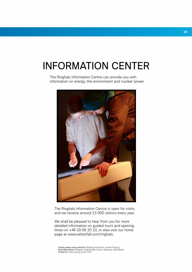
The Ringhals Information Centre is open for visits, and we receive around 13 000 visitors every year.
We shall be pleased to hear from you for more detailed information on guided tours and opening times on +46 20 66 20 10, or else visit our home page at www.vattenfall.com/ringhals.
The Ringhals Information Centre can provide you with information on energy, the environment and nuclear power.
iNForMaTioN CENTEr
rin
gha
ls 2
01
2
ringhals aBSE-43285 VäröbackaSweden
Phone: + 46 340 66 70 00Fax: + 46 340 66 51 84
[email protected]/ringhals
Electricity from nuclear power


