Introduction 2Features and Benefits 3Design Center Services 4Open-Web Truss Descriptions 4–5Specifying Economical Trusses 5Load Tables 6–11Truss Details 12–21Truss Bearing Clip Capacities 22Truss Dimensions 23Wind or Seismic Connections 24–26Wind Bracing 27Red-S™, Red-M™ and Red-H™ Truss Cap Plate Applications 27–28Bridging 28Allowable Duct Sizes 29Installation Bracing 30–31Long Span Installation Bracing 32Material Weights 33Snowdrift Loading 34Tech Support and Analysis 34Deflection Criteria 35Camber Criteria 35Nailing Information 36Fire and Sound 36Sound Details 36–37Q&A 38 Specifications 39
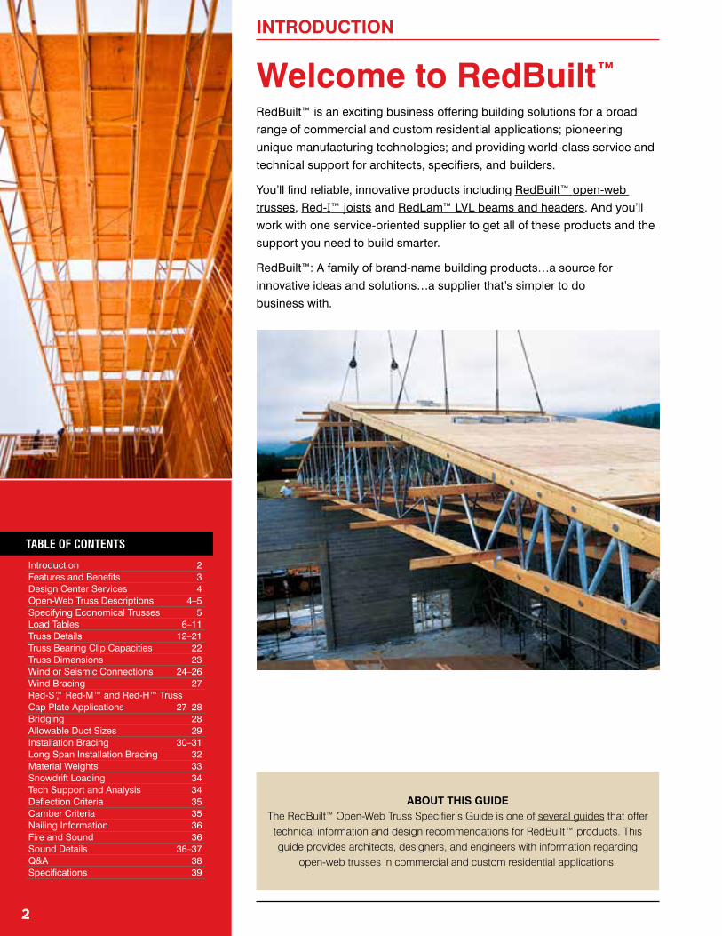
ABOUT THIS GUIDE The RedBuilt™ Open-Web Truss Specifier’s Guide is one of several guides that offer
technical information and design recommendations for RedBuilt™ products. This guide provides architects, designers, and engineers with information regarding
open-web trusses in commercial and custom residential applications.
Welcome to RedBuilt™
RedBuilt™ is an exciting business offering building solutions for a broad
range of commercial and custom residential applications; pioneering
unique manufacturing technologies; and providing world-class service and
technical support for architects, specifiers, and builders.
You’ll find reliable, innovative products including RedBuilt™ open-web
trusses, Red-I™ joists and RedLam™ LVL beams and headers. And you’ll
work with one service-oriented supplier to get all of these products and the
support you need to build smarter.
RedBuilt™: A family of brand-name building products…a source for
innovative ideas and solutions…a supplier that’s simpler to do
Any depth between minimum and maximum is available.
Open-web trusses are intended for dry use, untreated applications.
Upon request, RedBuilt™ can provide the following services for the products described in this Open-Web Truss Specifier’s Guide:
■ A complete design package including layout drawings (placement diagrams) and detailed design calculations.
■ Review and analysis of the application.■ Drawings or calculations sealed by a professional engineer.
OPEN-WEB TRUSS DESCRIPTIONS
Engineering Responsibility Position StatementRedBuilt™ is a manufacturer of proprietary structural components. It employs a staff of engineers to aid in the development, manufacture, and marketing of its products. RedBuilt™ does not replace or accept the responsibility of the design professional of record for any structure.
RedBuilt™ accepts the delegation of engineering responsibility only for the products it manufactures, provided that the application conditions are specified by the design professional of record, or other responsible party when a design professional is not engaged. RedBuilt™ provides engineering in the design of its products and does not displace the need on any project for a design professional of record.
Red-L™, Red-LT™ and Red-W™ TrussesTop Chords:
■ Red-L™ Trusses: 11⁄2 x 31⁄2" MSR lumber.*
■ Red-LT™ Trusses: 11⁄2" x 31⁄2" Timberstrand® LSL.
■ Red-W™ Trusses: 11⁄2" x 43⁄4" MSR lumber.
Bottom Chords: ■ Red-L™ and Red-LT™ Trusses:
11⁄2" x 31⁄2" MSR lumber.*
■ Red-W™ Trusses: 11⁄2" x 43⁄4" MSR lumber.
Webs: 1" and 11⁄8" diameter tubular steel members varying in gauge and diameter according to requirements. Minimum yield of 45,000 psi.
Weight: ■ Red-L™ and Red-LT™ Trusses: 3.75 to 4.25 lbs/ft
Any depth between minimum and maximum is available.
Our technical support team offers professional capabilities in the design and application of all RedBuilt™ products.
Building Codes and Product Acceptance: See ICC ES ESR-1774, L.A. City RR #22614
*RedLam LVL chords may be available for Red-L,™ Red-M,™ and Red-H™ truss series. Consult your technical representative for availability and limitations.
Installation ReviewAlthough responsibility for proper installation lies with the contractor-builder, RedBuilt™ provides detailed suggestions and guidelines for installation. If requested, a RedBuilt™ representative will visit the site to verify the contractor’s understanding of proper installation. RedBuilt™ engineers also are available to help solve job site application problems.
A minimum depth truss with a maximum plf loading (as shown in tables on pages 6–11) may not be the most economical solution. Designing to the maximum depth allowed for the application, and not maximizing loads in tables, will produce the most economical solution. More economical trusses can often be specified by considering the following two guidelines:
Deeper Can Be More Economical Consider Alternative Truss Series
32"
36"
32"
32"
32"
10-Panel Truss
Minimum Depth (Maximum PLF Capacity)
Example: Example:
9-Panel Truss
Economical Depth
Red-L™ Truss Series (Maximum PLF Capacity)
14-Panel Truss
Red-W™ Truss Series
9-Panel Truss
Red-S™ Truss Series
7-Panel Truss
Top chord bearing at each end provides the easiest installation and the most cost-effective truss system.
Note that these are general guidelines only and they are not reflective of all applications. Consult your local RedBuilt™ technical representative to assist you in specifying the most economical truss solutions for your particular applications.
Cost Savings of 12%±
OPEN-WEB TRUSS DESCRIPTIONS
SPECIfyING ECONOMICAL TRUSSES
Cost Savings of 20%±
Cost Savings of 23%±
In radius truss applications (Profiles 5, 6, 7, 9, and 10), allowable loads are reduced due to radial stresses. Contact your RedBuilt™ technical representative for job-specific possibilities.
Maximum top chord slope for Profile 4 (Radius Pitched) is 1⁄2:12 for Red-L™, Red-LT™ and Red-W™ truss series, and 3⁄8:12 for Red-S™ truss series.
■ Straight line interpolations may be made between depths and spans.
■ Values in shaded areas may be increased for repetitive-member use as follows: 7% for Red-L™ truss series and 4% for Red-LT™ truss series.
■ Bold italic values are controlled by minimum concentrated load analysis of 2,000 lbs. Higher loads are possible where minimum concentrated load analysis is not required by code. Contact your RedBuilt™ technical representative for assistance.
General Notes■ Values shown are for demonstration of maximum allowable load
capacities based on the following assumptions:
– Simple span, uniformly loaded conditions, with provisions for positive drainage (1⁄4:12 slope minimum) in roof applications.
– Span indicates distance from inside face to inside face of bearing. – Top chord no-notch bearing clips with 13⁄4" bearing. Higher values may be
possible with other types of bearing clips.
■ See pages 4 and 5 for available depths and profiles. For depths and profiles not shown, contact your RedBuilt™ technical representative for assistance. ■ Red numbers refer to 115% Total Load (TL).
for economical truss design, see page 5.
Trusses delivered to the jobsite are custom manufactured to resist only project specific application loads provided by the design professional. Actual trusses may not be able to resist the maximum loads shown in the tables above. For questions regarding actual truss capacity contact your RedBuilt™ technical representative.
To size floor trusses: Check both total load (100% TL) and live load (100% LL). When live load is not shown, total load will control. Total load values limit deflection to L /240. Live load values are based on the Commercial Floor Deflection Limit shown on page 36, and assume a nailed floor system. Live load (100% LL) values may be increased with a glue-nailed floor system; contact your RedBuilt™ technical representative for assistance.
To size roof trusses: Check the appropriate snow load area (115% TL) or non-snow load area (125% TL) value to determine the maximum allowable total load. Total load (115% TL and 125% TL) values limit truss deflection to L/180.
Consult local codes to verify deflection limits required for specific applications.
■ See pages 4 and 5 for available depths and profiles. For depths and profiles not shown, contact your RedBuilt™ technical representative for assistance. ■ Red numbers refer to 115% Total Load (TL).
Trusses delivered to the jobsite are custom manufactured to resist only project specific application loads provided by the design professional. Actual trusses may not be able to resist the maximum loads shown in the tables above. For questions regarding actual truss capacity contact your RedBuilt™ technical representative.
General Notes■ Values shown are for demonstration of maximum allowable load
capacities based on the following assumptions:
– Simple span, uniformly loaded conditions, with provisions for positive drainage (1⁄4:12 slope minimum) in roof applications.
– Span indicates distance from inside face to inside face of bearing. – Top chord no-notch bearing clips with 23⁄4" bearing for Red-W™ truss series
and standard bearing clips for Red-S™ truss series. Higher values may be possible with other types of bearing clips.
■ Straight line interpolations may be made between depths and spans.
■ Values in shaded areas may be increased for repetitive-member use as follows: 7% for Red-W™ truss series and 4% for Red-S™ truss series.
■ Bold italic values are controlled by minimum concentrated load analysis of 2,000 lbs. Higher loads are possible where minimum concentrated load analysis is not required by code. Contact your RedBuilt™ technical representative for assistance.
■ See pages 4 and 5 for available depths and profiles. For depths and profiles not shown, contact your RedBuilt™ technical representative for assistance. ■ Red numbers refer to 115% Total Load (TL).
for economical truss design, see page 5.
General Notes continued on page 9
Trusses delivered to the jobsite are custom manufactured to resist only project specific application loads provided by the design professional. Actual trusses may not be able to resist the maximum loads shown in the tables above. For questions regarding actual truss capacity contact your RedBuilt™ technical representative.
To size floor trusses: Check both total load (100% TL) and live load (100% LL). When live load is not shown, total load will control. Total load values limit deflection to L/240. Live load values are based on the Commercial Floor Deflection Limit shown on page 36, and assume a nailed floor system. Live load (100% LL) values may be increased with a glue-nailed floor system; contact your RedBuilt™ technical representative for assistance.
To size roof trusses: Check the appropriate snow load area (115% TL) or non-snow load area (125% TL) value to determine the maximum allowable total load. Total load (115% TL and 125% TL) values limit truss deflection to L/180.
Consult local codes to verify deflection limits required for specific applications.
16 21 27 33 40 47 17 55 19 62 22 73 25 83 28 90 32 96 35 101 38 106■ See pages 4 and 5 for available depths and profiles. For depths and profiles not shown, contact your RedBuilt™ technical representative for assistance. ■ Red numbers refer to 115% Total Load (TL).
for economical truss design, see page 5.
Trusses delivered to the jobsite are custom manufactured to resist only project specific application loads provided by the design professional. Actual trusses may not be able to resist the maximum loads shown in the tables above. For questions regarding actual truss capacity contact your RedBuilt™ technical representative.
■ See pages 4 and 5 for available depths and profiles. For depths and profiles not shown, contact your RedBuilt™ technical representative for assistance. For spans over 70 feet, see page 32 or contact your RedBuilt™ technical representative.
■ Red numbers refer to 115% Total Load (TL).
for economical truss design, see page 5.
General Notes continued on page 11
Trusses delivered to the jobsite are custom manufactured to resist only project specific application loads provided by the design professional. Actual trusses may not be able to resist the maximum loads shown in the tables above. For questions regarding actual truss capacity contact your RedBuilt™ technical representative.
To size floor trusses: Check both total load (100% TL) and live load (100% LL). When live load is not shown, total load will control. Total load values limit deflection to L/240. Live load values are based on the Commercial Floor Deflection Limit shown on page 36, and assume a nailed floor system. Live load (100% LL) values may be increased with a glue-nailed floor system; contact your RedBuilt™ technical representative for assistance.
To size roof trusses: Check the appropriate snow load area (115% TL) or non-snow load area (125% TL) value to determine the maximum allowable total load. Total load (115% TL and 125% TL) values limit truss deflection to L/180.
Consult local codes to verify deflection limits required for specific applications.
■ See pages 4 and 5 for available depths and profiles. For depths and profiles not shown, contact your RedBuilt™ technical representative for assistance. For spans over 70 feet, see page 34 or contact your RedBuilt™ technical representative.
■ Red numbers refer to 115% Total Load (TL).
for economical truss design, see page 5.
Trusses delivered to the jobsite are custom manufactured to resist only project specific application loads provided by the design professional. Actual trusses may not be able to resist the maximum loads shown in the tables above. For questions regarding actual truss capacity contact your RedBuilt™ technical representative.
Slope at Which Plate Must Be BeveledNo-Notch, U-Clip
2x8 2x6 2x4Low end >1⁄4:12 >3⁄8:12 >1⁄2:12High end >3⁄8:12 >3⁄8:12 >1⁄2:12
CantileverBeveled plate required at all slopes
Common
Beveled bearing plates are required for trusses with sloped top chords.
Beveled plates serve two functions: 1. Provide proper bearing for the bearing clip. 2. Avoid interference between the top chord
and the bearing plate.
Beveled plate, to suit roof slope, is required at all common bearings and cantilevered bearings
See page 22 for bearing reaction capacities
13⁄4"611⁄16" with Red-L™ and Red-LT™ trusses; 715⁄16" with Red-W™ trusses
13⁄4" 73⁄16" with Red-L™ and Red-LT™ trusses; 87⁄16" with Red-W™ trussesBearing capacity
varies with chord bearing length
Bearing capacity varies with chord bearing length
Strut bracing required and supplied by RedBuilt™.
See page 31.
Chord extensions and outriggers.
See page 15.
Typical blocking. See page 13, detail 10.
Starter strut (2x4 block) by contractor. Clips supplied by RedBuilt™.
Bridging clips installed by RedBuilt™
Edge blocking as required
Bridging. See page 28.
2" flange width
9"
2nd pin optional
Pre-notched plate not required
Maximum slope is 1⁄2:12. Contact your RedBuilt™ technical representative for truss depth less than 21". See pages 24–26 for additional information on Wind or Seismic Connections.
■ See detail 4 for flush mount.
1⁄4" flange thickness
Specify for high axial load
applications
13
RED-L™, RED-LT™ AND RED-W™ TRUSS DETAILS
5 Top Chord Bearing No-Notch Clip
6 Top Chord Bearing on Ledger No-Notch Clip
7 Bearing Block at Masonry Wall 8 Top Chord Bearing flush-Mount Bearing Clip (Dropped and Non-Dropped)
9 Red-I™ Joist Butting with Top Chord Bearing Truss
10 Typical Top Chord Bearing and Blocking No-Notch Clip
Two Simpson Strong-Tie® ST 2115
(or equivalent, by others) required
2x_ stud wall
2x_ platesWeb stiffener each
side of joist as required
Joist hanger
Do not grout solid—leave 1⁄2" clearance all around truss Beam
Red-L™, Red-LT™ and Red-W™ non-dropped truss
Bearing wall as occurs
Blocking to transfer vertical and diaphragm loads
Treated bearing block installed by RedBuilt™
Wall or strap tie as required. Use 10d (0.148" x 11⁄2") nails maximum.
Leave 1⁄2" clearance or provide vapor barrier at truss end.
Ledger
Red-S™, Red-M™, or Red-H™ trusses dropped with cap plate
41⁄2" minimum with Red-S™ truss 51⁄2" minimum with Red-M™ truss
6" minimum with Red-H™ truss
LSL chord end as required
1⁄4 gap
Blocking not shown for clarity See page 26 for axial tension or compression capacity information
14
RED-L™, RED-LT™ AND RED-W™ TRUSS DETAILS
See page 25 for lateral load capacity and for Red-L™ and Red-W™ alternate detail.
12 Top Chord Bearing on Steel Beam No-Notch Clip
11 Red-W™ Truss Top Chord Bearing Lateral No-Notch Clip
13 Top Chord Bearing Truss Butting with Red-S™ Truss
14 Bottom Chord Bearing with Butting Trusses U-Clip
15 Bottom Chord Bearing with Cross Bracing U-Clip
16 Top Chord Bearing at Skewed Wall No-Notch Clip
Elevation of skewed wall must be lowered to accommodate bearing block height
Red-L™, Red-LT™, Red-W™ trusses
31⁄2" minimum, steel beam or stud wall
51⁄2" minimum
3⁄8" diameter bolt by RedBuilt™
Metal cross bracing by RedBuilt™. See page 30.
Red-S™ truss
Bend tab over plate as required
Metal cross bracing by RedBuilt™. See page 30.
1" minimum, centerline of wall preferred
41⁄2" minimum2" high
continuous filler
87⁄16"
7"
Clip extension. Fill all nail holes over plate.
2,860 lbs reaction capacity at 100% Duration of Load; higher reactions require more bearing length
2,860 lbs reaction capacity at 100% Duration of Load for Red-L™, Red-LT™ and Red-W™ trusses; higher reactions require more bearing length
43⁄4"
15
RED-L™, RED-LT™ AND RED-W™ TRUSS DETAILS
The following minimum criteria were used to develop the values: 2x4 and 2x6: 2x8: Fv = 175 psi Fv = 175 psi Fb = 2,100 psi Fb = 900 psi (1) E = 1.8 x 10⁶ psi E = 1.6 x 10⁶ psi
Starter strut (2x4 block) by contractor. Clips supplied by RedBuilt™.
Strut bracing required and supplied by RedBuilt™. See page 31.
Beveled plate is required for all slopes greater than 1⁄4:12Low End High End
Low End High End
Beveled plate is required for all slopes greater than 1⁄8:12
5" max. when no beveled plate is used (slope is less than or equal
to 1⁄8:12)
Floor bridging. See page 28.
Bridging clips installed by RedBuilt™. See page 28.
Beveled plate is required for all slopes when trusses are cantilevered
See page 22 for bearing reaction capacities
Beveled plate is required for all slopes when trusses are cantilevered
22 Top Chord Bearing S-Clip
23 Bottom Chord Bearing Angle Clip
31⁄2"
65⁄8"51⁄2"
31⁄2"
23⁄4"
Maximum slope is 1⁄2:12. Contact your RedBuilt™ technical representative for truss depth less than 22". See pages 24–26 for additional information on Wind or Seismic Connections.
5⁄16" flange
thickness
2nd pin optional
21⁄2" flange width
9"
Specify for high axial load
applications
24 Top Bearing flush-Mount Clip (Heavy Duty)
17
27 Top Chord Bearing on Ledger flush-Mount Bearing Clip
28 Red-I™ Joist Butting with Red-S™ Truss S-Clip
29 Top Chord Bearing flush-Mount Bearing Clip (Dropped and Non-Dropped)
30 Top Chord Bearing with Butting Trusses S-Clip
31 Bottom Chord Bearing with Cross Bracing Angle Clip
32 Top Chord Bearing on Ledger S-Clip
Ledger Web stiffener each side of joist as required
Joist hanger
4x_ plate
2x_ plate
5" minimum
Non-droppedDropped with cap plate
Metal cross bracing by RedBuilt™. See page 30. 4x_ ledger
51⁄2" minimum, steel beam or stud wall
Weld bearing clip to steel beam
Optional detailSee page 26 for axial tension or compression capacity information
■ Values are limited by the published backspan capacity (plf).■ All Calculations assume a single 2x_ header of equal depth to the outriggers with the trusses at 48" on-center.■ For single 2x_ outriggers, use half of allowable load shown for double outriggers.■ Members evaluated for 300 lb. point load.
■ Values are limited by the published backspan capacity (plf).
■ Members evaluated for 300 lb. point load.
The following criteria were used to develop the values:
Fv = 285 psi Fb = 3,000 psi(1) E = 2.0 x 10⁶ psi
(1) For 12" depth For other depths, multiply by [ ]0.136
Deflection: 2L/360 at total load for floors (Live load=0.80 x total load) 2L/240 at total load for roofs (Live load=0.80 x total load)
The following minimum criteria were used to develop the values:
2x4 and 2x6: 2x8: Fv = 175 psi Fv = 175 psi Fb = 2,100 psi Fb = 900 psi (1) E = 1.8 x 10⁶ psi E = 1.6 x 10⁶ psi
(1) Multiply by CF=1.2
+
Outrigger Deflection: 2L/360 at LL for floors (Live load = 0.80 x total load) 2L/240 at TL for roofs
Outrigger Deflection = 7WL4 24EI
482WL EI
12d
33 Top Chord Bearing Cantilever 34 Bottom Chord Bearing Cantilever
35 Top Chord Extension
Main span Cantilever
Bottom chord splice kit available for installing over beam
Bottom chord bracing may be required
1⁄2" maximum overhang per 2x_ bearing plate
51⁄2" minimum
To check cantilever capacity, contact your RedBuilt™ technical representative To check cantilever capacity, contact your RedBuilt™ technical representative
Main span Cantilever
Bottom chord bracing may be required
71⁄4" minimum. Inquire about possible reductions.
Metal cross bracing or Red-I™ blocking provided by RedBuilt™. See page 30.
3" minimum
See table
Sheathing layout should be considered when locating this member
19
Starter strut (2x4 block) by contractor. Clips supplied by RedBuilt™.
Edge blocking as required
Strut bracing required and supplied by RedBuilt™. See page 31.Floor bridging. Bridging clips supplied
by RedBuilt™. See page 28.
Bottom chord restraint. See page 31.
37 Red-M™ Truss Top Chord Bearing S-Clip
40 Top Chord Bearing P-Clip
39 Top Chord Bearing Z-Clip
38 Red-M™ Truss Bottom Chord Bearing Angle Clip
41 Bottom Chord Bearing T-Clip
55⁄8"65⁄8"3" with Red-M™ truss
31⁄2" with Red-H™ truss
Clip will overhang 1⁄4" with Red-M™ truss
47⁄8"
63⁄8"
71⁄2"± with Red-M™ truss 8"± with Red-H™ truss
See page 22 for bearing reaction capacities
35⁄8"
73⁄8"21⁄2"
Clip will overhang 1⁄4" with Red-M™ truss
23⁄4" with Red-M™ truss 31⁄2" with Red-H™ truss
11⁄2" with Red-M™ truss 13⁄4" with Red-H™ truss
7"± with Red-M™ truss 8"± with Red-H™ truss
311⁄16" with Red-M™ truss 53⁄4" with Red-H™ truss
51⁄8" with Red-M™ truss 53⁄4" with Red-H™ truss
4"
63⁄4"
31⁄4" with Red-M™ truss 31⁄2" with Red-H™ truss
Maximum slope is 1/2 :12. Contact your RedBuilt™ technical representative for truss depth less than 31". See pages 24–26 for additional information on Wind or Seismic Connections.
2nd pin optional
9"
Flange width: 3" with Red-M™ truss 4" with Red-H™ truss
Flange thickness:
3⁄8" with Red-M™ truss 1⁄2" with Red-H™ truss
42 Top Bearing flush-Mount Clip (Heavy Duty)
RED-M™ AND RED-H™ TRUSS DETAILS
Specify for high axial load
applications
20
43 Beveled Plate Requirements
44 Typical Top Chord Extension
45 Top Chord Bearing with Butting Trusses Z-Clip
46 Top Chord Bearing flush-Mount Bearing Clip (Dropped and Non-Dropped)
47 Top Chord Bearing Cantilever Z-Clip
48 Bottom Chord Bearing Cantilever T-Clip
51⁄2" minimum with Red-M™ truss 7" minimum with Red-H™ truss
51⁄2" minimum with Red-M™ truss 7" minimum with Red-H™ truss
1⁄2" maximum overhang per 2x_ bearing plate
Beveled plates serve two functions: 1. Provide proper bearing for bearing clips. 2. Avoid interference between top chords and
Truss depth, design load, and web angle may limit header size. Check feasibility with your local RedBuilt™ technical representative.
Load transfer blocks are required only when the load is imposed from the side
Inverted bearing clip may be required to transmit load directly to pin
Load
Load
2x_ sleepers
Required clearance equal to deflectionClip attached to
truss onlyCantilever
Fasten ledger to load transfer blocks as specified by RedBuilt™.
Load transfer block spacing varies per design. May not be required at every panel.
Diagonal bracing may be required to prevent truss rotation.
Header hanger by RedBuilt™
Use 5⁄8" bolts for single chord trusses, 3⁄4" bolts for double chord trusses
Double 2x_ as required (by others)
Double top chord extension (with Red-L™, Red-LT™, Red-W™ trusses)
Load determines number of trusses required
Concentrated and Non-Uniform LoadsFor the most efficient use of RedBuilt™ products carrying concentrated loads or non-uniform loads, and/or used in conditions other than simple spans, consult your RedBuilt™ technical representative for precise sizing. As a general rule, extra members should be added to the system to carry concentrated loads such as bearing partitions, air-conditioners, and other mechanical equipment. Handling concentrated loads in this manner usually provides the most economical system and also helps ensure more uniform deflection.
Maximum Allowable Header Clip Load Per Truss
■ Table values do not consider header or header connection designs.■ Table values are based on large truss pins. Contact your local RedBuilt™ technical representative
to ensure that the truss application works with the corresponding header reaction.
OPEN-WEB TRUSS DETAILS
22
Truss Series Clip Type Detail
NumberBearing
(Top or Bottom)Bearing (2)
Length (min.)
Reaction Capacity (lbs)Duration of Load
100% 115% 125%
Red-L™
Red-LT™
6" No-Notch 2 T 13⁄4" 2,860 3,290 3,2906" No-Notch 2 T 21⁄2" 3,025 3,480 3,7806" No-Notch 2 T 31⁄2" 3,150 3,620 3,925
U-Clip 3 B 23⁄4" 4,400* 4,845* 4,845*
Red-W™
6" No-Notch 2 T 13⁄4" 2,860 3,290 3,2906" No-Notch 2 T 25⁄8" 3,500 4,025 4,300
U-Clip 3 B 23⁄4" 4,850 5,580 5,880
Red-S™S-Clip 22 T 23⁄4" 5,390 5,390 5,390
Angle Clip 23 B 31⁄2" 5,325 6,125 6,655
Red-M™
S-Clip 37 T 21⁄2" 3,990* 4,330* 4,330*Z-Clip(1) 39 T 23⁄4" 7,390 7,390 7,390P-Clip 40 T 31⁄4" 8,310 8,310 8,310
Angle Clip 38 B 4" 6,085 7,000* 7,610*T-Clip 41 B 3" 6,500 6,500 6,500
Red-H™
Z-Clip (1) 39 T 31⁄2" 9,200 9,200 9,200P-Clip 40 T 31⁄2" 9,100 9,200 9,200T-Clip 41 B 31⁄2" 9,260* 10,650* 11,575*
S-Clip 37 T 31⁄8" 430 515 840 840 810 840 840 840Z-Clip 39 T 3" 1,000 1,200 1,920 2,310P-Clip 40 T 51⁄2" 1,000 1,200 1,920 2,310
Flush-Mount 42 T 25⁄8" 1,300 1,570 2,490 3,000Angle Clip 38 B 4" 520 625 840 840 840 840 840 840
T-Clip 41 B 3" 1,000 1,200 1,920 2,310
Red-H™
Z-Clip 39 T 41⁄4" 1,000 1,200 1,920 2,310P-Clip 40 T 6" 1,000 1,200 1,920 2,310
Flush-Mount 42 T 31⁄2" 1,300 1,570 2,490 3,000T-Clip 41 B 31⁄2" 1,000 1,200 1,920 2,310
(1) Increased bearing length is required when truss slope meets or exceeds ¼:12.(2) Sloped applications may require longer bearing lengths.■ Values are based on bearing plate material (with Fc⊥ = 405 psi, SG = 0.42), except where they are marked with an asterisk (*). * Use a Douglas-fir bearing plate (or equivalent).
(1) Increased uplift capacities are available with clip modifications. Please contact your RedBuilt™ representative.Nailing Requirements:■ Values require a quantity of 6 nails unless in shaded cells or in bold italic. ■ Values in shaded cells require a quantity of 10 nails.■ Values in bold italic require a quantity of 12 nails.■ All values are based on spruce-pine-fir bearing plate material (SG = 0.42).
OPEN-WEB TRUSS BEARING CLIP CAPACITIES
23
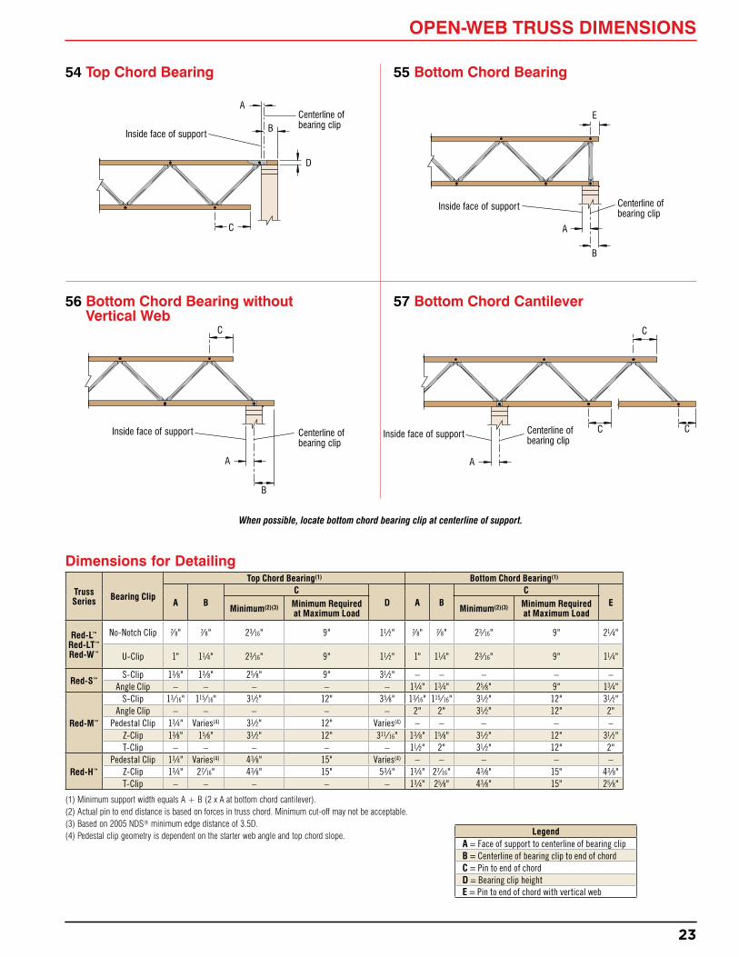
54 Top Chord Bearing 55 Bottom Chord Bearing
56 Bottom Chord Bearing without vertical Web
57 Bottom Chord Cantilever
Inside face of support
Centerline of bearing clip
A
B
D
C
Inside face of support Centerline of bearing clip
E
A
B
C
Inside face of support Centerline of bearing clip
A
B
Truss Series Bearing Clip
Top Chord Bearing(1) Bottom Chord Bearing(1)
A BC
D A BC
EMinimum(2)(3) Minimum Required
at Maximum Load Minimum(2)(3) Minimum Required at Maximum Load
(1) Minimum support width equals A + B (2 x A at bottom chord cantilever).(2) Actual pin to end distance is based on forces in truss chord. Minimum cut-off may not be acceptable.(3) Based on 2005 NDS® minimum edge distance of 3.5D.(4) Pedestal clip geometry is dependent on the starter web angle and top chord slope.
C
Inside face of support Centerline of bearing clip
C C
Dimensions for Detailing
LegendA = Face of support to centerline of bearing clipB = Centerline of bearing clip to end of chordC = Pin to end of chordD = Bearing clip heightE = Pin to end of chord with vertical web
When possible, locate bottom chord bearing clip at centerline of support.
A
OPEN-WEB TRUSS DIMENSIONS
24
Ledger
Wall tie
Masonry or concrete wall
58 Red-LT™ Truss Wall Ties
DO NOT attach bottom chord to wall when using a top chord wall tie
Wall and Strap Ties for Red-LT™ TrussesExtensive testing was conducted to determine the ability of LSL to resist splitting under close on-center nailing. The results of this testing indicate that LSL will not split, even with multiple rows of 12d (0.148" x 3¼") or smaller nails at 11⁄2" on-center (or 13⁄4" on-center for 16d [0.162" x 31⁄2"] nails). This allows for the use of any anchor, wall tie, or strap currently offered by Simpson Strong-Tie Company Inc.
Listed below is a small sample of the various nail-based straps and ties offered by Simpson Strong-Tie Company Inc. Please consult their catalog or the USP Structural Connectors® catalog for additional options.
59 Red-L™, Red-LT™ and Red-W™ Trusses with Shear Block
60 Red-L™, Red-LT™, Red-W™ and Red-S™ Trusses with Steel Connector
61 Red-M™ Truss with Wall Tie
63 Red-W™ Truss Top Chord Bearing Lateral No-Notch Clip
63 (Alternate) Red-L™ and Red-W™ Standard No-Notch Clip
62 Red-H™ Truss with Wall Tie
HD3B (by others) each side, connected with two 5⁄8" bolts Red-L™, LT, or W: HD3B
(by others) each side, connected with two 5⁄8" bolts
Concrete or CMU wall(Anchorage design by others.)
Ledger
31⁄2" x 31⁄2" x 15" Shear Block (attached by RedBuilt™)
Ledger
HD3B (by others) each side of chord, connected with two 5⁄8" through bolts. Truss chord, filler, and filler holes to be field-drilled by others.
No closer than 16"
Maximum truss assembly tension capacity is 3,500 lbs at 160%. Truss geometry, especially at shallow depths, may limit capacity.
Maximum truss assembly tension capacity is 4,450 lbs for Red-L™, Red-LT™ and Red-W™ trusses and 6,875 lbs for Red-S™ trusses at 160%. Truss geometry may limit capacity.
Contact your RedBuilt™ technical representative for more information.
Maximum truss assembly tension capacity is 3,840 lbs with MSR chords and 6,840 lbs with RedLam™ LVL chords at 160%. Truss geometry may limit capacity.
Contact your RedBuilt™ technical representative for more information.
Maximum truss assembly tension capacity is 4,600 lbs with MSR chords and 8,200 lbs with RedLam™ LVL chords at 160%. Truss geometry may limit capacity.
Contact your RedBuilt™ technical representative for more information.
Lateral No-Notch Clip Allowable Loads (lbs)
Ledger
HD5B (by others) each side of chord, connected with two 3⁄4" through bolts. Truss chord, filler, and filler holes to be field-drilled by others.
No closer than 16"
■ Values are based on bearing plate width SG = 0.50. For SG = 0.42, multiply table values by 0.86. ■ For other uplift loads, interpolation is permitted.
Red-S™: HD5B (by others) each side, connected with two 3⁄4" bolts
Concrete or CMU wall(Anchorage design by others.)Ledger
Pre-manufactured steel connectors (attached by RedBuilt™)
11⁄2" x 31⁄2" LSL each side (attached by RedBuilt™)
Bend tab over plate
as required
43⁄4"87⁄16"
7"
Clip extension. Fill all nail holes over plate.
Fasteners into chord cut-off. (Pre-drill recommended.)
Design and spacing limitations per 2005 NDS®.
2x8 plate
Top View
WIND OR SEISMIC CONNECTIONS
Red-S™ shown,others similar.16" min. trussdepth required
Concrete or CMU wall(Anchorage design by others.)
Concrete or CMU wall(Anchorage design by others.)
Contact your RedBuilt™ technical representative for more information.
Allowable Load (lbs) at 133% Allowable Load (lbs) at 160%Masonry Concrete Masonry Concrete
MPAI32 16 0.148" x 11⁄2" 1,960 1,960 2,355 2,355MPAI44 24 0.148" x 11⁄2" 2,865 2,865 2,865 2,865
LTT20B(1) 10 0.148" x 11⁄2" 1,250 1,450 1,500 1,740LTTI31 18 0.148" x 11⁄2" 2,185 2,185 2,310 2,310PAI18(1) 7 0.148" x 11⁄2" 875 875 1,055 1,055PAI23(1) 12 0.148" x 11⁄2" 1,505 1,505 1,805 1,805PAI28(1) 18 0.148" x 11⁄2" 2,255 2,255 2,705 2,705PAI35(1) 23 0.148" x 11⁄2" 2,815 2,875 2,815 3,460
Simpson Strap
Required Nails Nail Size Allowable Load
(lbs) at 133%Allowable Load (lbs) at 160%
MST37(1)(2) 42 0.162" x 21⁄2" 4,395 5,080MST48(1)(2) 46 0.162" x 21⁄2" 4,845 5,310MSTI48(2) 48 0.148" x 11⁄2" 4,350 5,080MSTI60(2) 60 0.148" x 11⁄2" 5,080 5,080MSTI72(2) 64 0.148" x 11⁄2" 5,080 5,080
LSTI49 32 0.148" x 11⁄2" 2,580 3,100LSTI73 48 0.148" x 11⁄2" 3,870 4,215
LSTA36(2)(3) 24 0.148" x 21⁄4" 1,640 1,640MSTA36(2)(3) 26 0.148" x 21⁄4" 2,050 2,050
(1) Not suitable for Red-S™ trusses.(2) LSL chord end or cap plate required for strap nailing.(3) Per NDS® 2005, no reduction has been considered for 10d x 21⁄4" nails in lieu of specified 10d x 3" nails.
(1) LSL chord end or cap plate required for strap nailing.
Wall Ties
Strap Ties
67 Wall and Strap Ties for Red-L™, Red-W™, Red-S™, Red-M™ and Red-H™ Trusses
DO NOT attach bottom chord to wall when using any top chord bearing truss
See page 13, detail 6, for more information
LSL chord end as required
(1) With or without top chord nailer.■ Design professional of record shall provide attachment for clip to bearing.
66 Double Chord flush-Mount Bearing Clip with Nailer
2nd pin optional
64 Single Chord flush-Mount Bearing Clip
2nd pin optional
9"
2" flange width 1⁄4" flange
thickness
Flange width:21⁄2" with Red-S™ truss3" with Red-M™ truss4" with Red-H™ truss
WIND OR SEISMIC CONNECTIONS
Flange thickness5⁄16" with Red-S™ truss 3⁄8" with Red-M™ truss1⁄2" with Red-H™ truss
11⁄2" for 2x top chord nailer(not shown here for clarity).
27
RED-S™, RED-M™ AND RED-H™ TRUSS CAP PLATE APPLICATIONS
70 RedBuilt™ Open-Web Truss with Cap Plate
71 Double Chord Open-Web Truss with SIP or Tectum Panels
Cap plates provide the following functions:
■ Transfer seismic/wind strap loads (LSL cap plate only).
■ Enhance diaphragm nailing capabilities.
■ Provide diaphragm shear transfer at continuous panel joints (required at all high shear diaphragms).
■ Eliminate interference between subpurlins and truss pins in panelized roof systems.
■ Required to provide adequate attachment base for structural insulated panels (SIPs) or Tectum deck applications.
When uplift on cap plate-to-truss connection exceeds 104 plf, contact your RedBuilt™ representative
2x_ cap plate
Fastener larger than conventional nails
Plant nails by RedBuilt™
2x4 MSR cap by RedBuilt™ (not suitable in strap applications because the combi-nation of deck, strap, and plant nailing will split the MSR cap)
10d (0.148" x 21⁄4") deck nails (maximum 3 rows at 6" on-center in each panel)
Sawn Lumber Cap Plate
LSL Cap Plate (Suitable for straps. See page 26.)
11⁄2" x 31⁄2" LSL cap plate
10d (0.148" x 21⁄4") deck nails (maximum 3 rows in each panel). Closest nail spacing: – 11⁄2" on-center without straps – 21⁄2" on-center with straps. See page 36.
Plant nails by RedBuilt™
Plant nailing varies per material
Butt joints as they occur
2x4 MSR or 11⁄2" x 31⁄2" LSL
cap plate
For diaphragm nails, use 21⁄4" max. length deck nails to eliminate nail-spacing limitations with truss chords
Truss bottom chord bracing may be required by building code provisions for wind uplift design when roof trusses do not have direct applied ceilings. Project engineer shall specify wind load; contact your RedBuilt™ representative for specific wind bracing stability requirements.
68 Cross Bracing with 2x4 NailerMetal cross bracing by RedBuilt™ (see plan for locations). Attach bracing as trusses are installed.
2x4 nailer by others. Attach to truss bottom chord with two 10d x 3" nails minimum.
Splice nailer together with three 10d x 3" nails each side through 2x4x24 block (1' on either side of splice).
69 Cross Bracing with Bridging Row
Metal cross bracing by RedBuilt™ (see plan for locations). Attach bracing as trusses are installed.
Bracing row
For wind bracing on Red-S™, Red-M™ and Red-H™ trusses (Cross bracing may not actually cross)
For wind bracing on Red-L™, Red-LT™ and Red-W™ trusses (Cross bracing may not actually cross)
72 Typical Double Chord Open-Web Truss with 2x_ Subpurlin
73 Double Chord Open-Web Truss with Continuous Panel Joint
Nail spacing is limited by truss chords. See page 36.
Option: Sheathing cap plate can serve as continuous joint nailer
Continuous panel joint11⁄2" x 31⁄2" MSR or LSL cap plate
(LSL adds strap capacity) 2x4 subpurlin, typical
Space subpurlins to avoid interference with pins
Red-L™, Red-LT™ and Red-W™ Trusses Bridging is required for all floor and roof applications
Truss SpacingSize of ContinuousBridging Member
Floor or Roof12"–16" o.c. 2x4(1)(2)
19.2"–32" o.c. 2x6(1)(2)
48" o.c. 2x6(1)(3), 2x8(4)
(1) Minimum 1650 Fb grade MSR for roof application.(2) If minimum 2100 Fb grade is specified, 2x4 bridging
may be used, up to 24" on-center.(3) Roof only.(4) Douglas fir-larch or southern pine, minimum grade #2.
11⁄2" nails by RedBuilt™
Bridging clip supplied and installed by RedBuilt™
16d (31⁄2") nails
Lap approximately 12"
2x_ bridging is designed to transfer 500 lb load
Field bend bridging clip approximately 30 degrees before nailing to bridging row
Sawn Lumber BridgingTruss Bridging Span No. of Rows
Roof Truss Bridging(1)(2)
Up to 16' 116'+ to 35' 235'+ to 55' 3
55'+ 4
Floor Truss Bridging(2) Without
a Directly Applied Ceiling
Up to 10' 110'+ to 24' 224'+ to 32' 3
32'+ 4
Floor Truss Bridging(2) With
a Directly Applied Ceiling
Up to 22' 122'+ to 32' 232'+ to 42' 3
42'+ 4
Bridging Rows
(1) Additional bracing may be required when trusses are to be installed out of plumb greater than 1⁄4:12. Contact your RedBuilt™ representative.
(2) Bridging is required in cantilevers when the length of cantilever exceeds 3 times the truss depth.
Bridging must be attached to a minimum of
three trusses
Truss Spacing Size of ContinuousBridging Member
12"–16" o.c. 2x4(1)(2)
19.2"–32" o.c. 2x6(1)(2)
48" o.c. 2x6(1), 2x8(3)
(1) Minimum 1650 Fb grade MSR.(2) If minimum 2100 Fb grade is specified, 2x4
bridging may be used, up to 24" on-center.(3) Douglas fir-larch or southern pine, minimum
grade #2.
Sawn Lumber floor Bridging
75 Red-M™ and Red-H™ Trusses
Field bend the bridging clip approximately 30 degrees before nailing to the bridging row
Bridging clip supplied and installed by RedBuilt™
Bridging clip supplied and installed by RedBuilt™ Five 16d (31⁄2") nailsFive 16d (31⁄2") nails
Bridging with 12" lap splicesBridging with
12" lap splices
Bridging CriteriaBridging is used to make each truss act with those next to it (load sharing) and minimize or equalize deflections from non-uniform loads. Bridging should not be confused with bracing, which has an entirely different purpose.
Roof Systems do not require bridging because differential deflections, vibrations, etc. are typically not a problem with roof systems. However, we do require bridging for load sharing with Red-L™, Red-LT™ and Red-W™ trusses because of their single-member chords and their common use in relatively long spans with wide on-center spacing.
Floor Systems perform better under typical loads—particularly with regard to deflection and vibration—if they have an effective bridging system.
Red-S™, Red-M™ and Red-H™ TrussesRoof: Bridging not required (except for long-span modular-installation applications. See page 32.)
Floor: Bridging required at 12' on-center maximum.
74 Red-S™ Trusses
RED-S™, RED-M™ AND RED-H™ TRUSS CAP PLATE APPLICATIONS
These tables are based on heaviest loads (shortest panels). Check with your RedBuilt™ representative for more precise sizing.
Duct size may not apply near bearings. Consult your RedBuilt™ representative in these cases.
H
W
How to read these tables: “H” dimensions are in the column heads “W” dimensions are in the body of the tables
Example: For a 24" Red-L™ truss, possible sizes are 4" x 21", 6" x 18", 8" x 16", and 10" x 13"
Red-S™ Trusses
Red-M™ Trusses Red-H™ Trusses
Truss Depth
Load Range (plf)
Duct Size
14" ANY 9"16" ANY 10"
18"0–150 12"
over 150 10"
20"0–150 13"
over 150 11"
22"0–150 13"
over 150 11"
24"0–150 14"
over 150 12"
26"0–150 15"
over 150 12"
28"0–150 16"
over 150 12"
30"0–150 16"
over 150 13"
32"0–150 17"
over 150 13"
34"0–150 17"
over 150 14"
36"0–150 18"
over 150 15"
38"0–150 18"
over 150 16"
40"0–150 19"
over 150 18"
Truss Depth
Load Range (plf)
Duct Size
16" ANY 9"
20"0–250 13"
250–350 12"
24"0–175 16"
175–370 14"
28"0–150 19"
150–250 17"250–400 15"
32"0–115 22"
115–180 20"180–300 18"
34"0–115 23"
115–180 21"180–380 18"
36"0–115 24"
115–200 21"200–350 19"
40"0–110 26"
110–180 23"180–360 20"
44"0–115 27"
115–200 24"200–300 21"
48"0–115 28"
115–200 25"200–300 22"
Truss Depth
Load Range (plf)
Duct Size
21" ANY 11"24" ANY 13"27" ANY 15"30" ANY 17"
33"0–110 21"
110–200 19"200–300 17"
36"0–100 24"
100–150 22"150–280 19"
39"0–80 26"
80–150 23"150–250 20"
42"0–75 28"
75–150 24"150–275 20"
Truss Depth
Load Range (plf)
Duct Size
30" ANY 16"33" ANY 17"36" ANY 18"
39"0–150 23"
150–300 20"
42"0–150 25"
150–300 21"
45"0–125 27"
125–250 23"250–300 21"
48"0–125 29"
125–200 27"200–300 23"
51"0–120 30"
120–180 28"180–300 24"
54"0–130 32"
130–200 29"200–300 24"
Tables are applicable only for uniform loads. For trusses designed for office floor conditions requiring concentrated loads, or for any other non-uniform loads, call your RedBuilt™ representative.
77 Round Ducts See tables below for outside diameter duct size
Duct size may not apply near bearings. Consult your RedBuilt™ representative in these cases.
Installation bracing for open-web trusses is required to prevent lateral buckling of the chord members, until they are stabilized by connection to the sheathing and by permanent bracing of the completed structure (as designed). Installation bracing includes strut bracing rows, cross bracing at bottom chord bearing conditions, bottom chord restraint, and braced end wall or diaphragm restraint adequate to support the strut bracing rows. The criteria used for this installation bracing assume either of the following conditions:
■ The truss carries its own weight plus the weight of applied sheathing and two 250-pound workers concentrated at 1⁄3 points of the span
OR
■ An unloaded truss with a 30 mph wind
Bracing for construction loads equivalent to or beyond these loads is the responsibility of the installer. Bracing must be installed as each truss is put in position.
All trusses are laterally unstable until properly braced. The longer the span, the more care is required. Adequate restraint is necessary at all stages of construction.
Complete stability is not achieved until all bracing and decking is completely installed and properly fastened.
Installation bracing and procedures, as well as the safety of the workers, are the responsibility of the installer.
For more information, see RedBuilt™’s Open-Web Truss Installation Guide (Available online at www.RedBuilt.com).
Installation Bracing for RedBuilt™ Open-Web Trusses
General Notes ■ Bottom chord restraints are 1x4 (minimum) nailers and are attached to the top of
the bottom chord with two 8d (21⁄2") nail for double chord trusses only. Materials are to be provided by the installer.
■ Bridging, when specified, may be used instead of bottom chord restraint.
Laterally braced end wall, beam, or ledger
2x4 starter strut (by others)
Cross bracing at bottom bearing
Bottom chord restraint at midspan for double chord trusses at spans over 40'
Bottom chord restraint adjacent to all top bearing conditions
No connection (unless otherwise noted)
Strut bracing row spacing. See page 31.
Cross bracing is provided for all open-web trusses at bottom chord bearing conditions. Install cross bracing as each truss is set. Maximum lateral load is 500 lbs per truss.
Cross bracing by RedBuilt™
Cross bracing by RedBuilt™
Cross Bracing
Typical Application
Installation Tolerances Permitted
Vertical Alignment Tolerance Overhang Tolerance at Bearing (Red-S™ bearing shown)
Bottom chord of truss should not be out of square with deck by more than 1⁄4:12 of truss
depth. Example: 1⁄2" for a 24" depth truss
1⁄4" maximum overhang* for all truss-bearing hardware
* 1⁄2" maximum overhang for Red-M™ series trusses with Z-Clip or Pedestal bearing hardware
To provide proper performance, trusses should not vary more than 1⁄2" from a straight line
Strut BracingStrut bracing is a required accessory with all open-web truss applications and is provided by RedBuilt™. Strut bracing should be placed in equally spaced rows. See below. Strut bracing for roof systems is attached as shown in the top detail at right. Strut bracing for floor systems is to be attached to the bottom of the top chord member to avoid interference with the direct attachment of sheathing.
Roof
Floor
Strut bracing
Bottom Chord Restraint for Red-S™, Red-M™ and Red-H™ TrussesBottom chord restraint is required to stabilize the bottom chord and is typically provided by the installer.
Bracing may be required at cantilevers as determined by RedBuilt™.
Attach 1x4 minimum nailer to top of bottom chord with two 8d (21⁄2") nail in each chord member
Bridging or nailers as shown by RedBuilt™
Nailer required at all top chord bearing conditions
Nailer required at midspan for spans beyond 40'-0". Bridging may serve in place of nailers. See bridging information on page 28.
Installation Requirements
Starting Bracing—No Laterally Braced End Wall or Beam
Truss Series Strut Bracing Row Spacing
Red-S™ 10' o.c.Red-L™, Red-LT™,
Red-M™ and Red-H™ 12' o.c.
Red-W™ 14' o.c.
Required SpacingMaximum Number of Erected Trusses Before Sheathing is Required
■ Strut bracing required and supplied by RedBuilt™. See above for installation requirements.
■ Sheath and nail per project architect, engineer, or local building code. See page 30 for allowable nailing into truss chords.
■ Per bay of trusses.
INSTALLATION BRACING
31
RedBuilt™ open-web trusses with spans beyond 70 feet are available only if all of the following additional requirements are satisfied. Review each of the following requirements with your RedBuilt™ representative prior to sizing and detailing our products in any application involving spans beyond 70 feet.
1. There must be a responsible architect and/or engineer of record throughout the design and construction period of the project.
2. The responsible architect or engineer must include the following statement in the job specifications: “The trusses shall be installed in rigid modules at least 8 feet in width, accurately assembled in a jig with final sheathing permanently and totally attached while on the ground. Specified bridging shall be installed in each module as detailed.”
3. Only structural panel sheathing will be permitted.
4. The purchaser-contractor must sign an addendum to our standard purchase agreement that contains the above requirements.
5. Prior to execution of the purchase agreement, the specifications and details of the job must be submitted to and reviewed by RedBuilt™ engineering along with a description of the installation procedures proposed to be used. Review will be solely with respect to the above requirements.
The following are sketches of possible rigid modules that would satisfy the condition specified in requirement 2.
Long Spans— Over 70 feet
Module with Sheathing Overhang—Trusses at 32" On-center
Module with Sheathing Overhang—Trusses at 48" On-center
Module with Sheathing filler Panel—Trusses at 48" On-center
Sheathing support as required
Filler panel installed after placing module
8' module
Attach sheathing to previously set module
8' module
Overhang
Attach sheathing to previously set module
8' module
Overhang
Bridging as detailed by RedBuilt™
Bridging as detailed by RedBuilt™
A cap may be required over double chord open-web trusses
Wind direction, site exposure, and roof type and shape are some of the factors that can dramatically influence the accumulation of snow on a roof structure. ASCE 7 (Minimum Design Loads for Buildings and Other Structures) and the applicable building code, as well as other local state and regional codes, provide guidelines for calculating snowdrift loadings on all types of building construction.
Drifts usually occur at locations of discontinuity in a roof such as at parapet walls, valleys, or where a high roof meets a low roof. Closer on-center spacing or additional support may be required at these locations. The examples above illustrate potential snowdrift conditions.
The project design professional is ultimately responsible for determining any additional loads due to snow drifting.
Product Application Assumptions
RedBuilt™ open-web trusses are analyzed as pin-connected trusses with continuity in the top chord member, which receives the superimposed loading. Allowable truss-member forces are designated in the product acceptance criteria or derived from material stresses therein. Chord members are analyzed considering both net section at panel points and gross sections between the panels. Allowable web member forces consider gross and net sections, pin bearing and buckling. Pin-connection details consider allowable bearing in the wood for both parallel and perpendicular-to-grain direction. Reaction detail analysis includes allowable bearing, induced moments where applicable, and detail stresses. Stress and deflection are calculated by the displacement method. All of the above is substantiated through continual testing.
Analysis Procedure
TECHNICAL SUPPORT AND ANALySIS
Our guarantee is subject to an adequate supporting structure for our products. The design of the entire structure is not the role of RedBuilt™, nor can we assume accountability for the full function of the roof or floor system. We can only be responsible for the internal design integrity of our own products, which are structural components of roof and floor systems that are necessarily designed by others.
Our guarantee is also subject to adequate lateral support to the compression chord of our products unless specific design provisions account for other lateral support conditions. Continuous lateral support is provided by 8d (21⁄2") nails at 24" on-center minimum for Red-L™, Red-LT™ and Red-W™ trusses, and by 8d (21⁄2") nails at 12" on-center staggered to each of the double chord members minimum for Red-S™, Red-M™, and Red-H™ trusses, all connected to an adequate diaphragm or total lateral strength system.
The magnitude, direction, and location of all design loads are as specified by the building designer. The review of this loading by our personnel is only for purposes of designing our product.
Other application assumptions are referenced on the terms and conditions of our purchase agreement contract.
Full-scale tests have shown repeatedly that RedBuilt™ products have deflection characteristics that are consistently predictable by calculation, with minimal set after load withdrawal.
The graph below shows that RedBuilt’s recommended deflection limit for residential and commercial floors is more restrictive than the minimum required by typical building codes. The floor load tables shown on pages 6–12 of this guide were developed based on the Commercial Floor Deflection Limit shown in the graph below.
Deflection criteria will vary by application. In a roof system, excessive deflection would be unsightly and could cause ceiling cracks and/or drainage problems. Floor systems, however, have entirely different—and usually much more restrictive—deflection requirements due to an occupant’s perception of floor performance and feel.
The fundamental frequency of a floor system can be a good predictor of performance. Contact RedBuilt™ to discuss floor system performance for applications that are sensitive to vibration.
Floors: ■ Maximum deflection at live load limited as indicated above.
■ Movable partition loads need not be considered.
Roofs: ■ Sloped Roofs—1⁄4" to 12" per foot, maximum deflection L/180 at total load
■ Plaster Ceilings—Also check L/360 at live load
RedBuilt™ Recommended Deflection Criteria
Camber Criteria
5' 10' 15' 20' 25' 30' 35' 40' 45' 50' Span (ft)
Defle
ctio
n at
Mid
span
(in.
)
2"
13⁄4"
11⁄2"
11⁄4"
1"
3⁄4"
1⁄2"
1⁄4"
0
L ⁄180 L ⁄240
L ⁄ 360
L ⁄480
L ⁄ 600
Commercial Floor Deflection Limit (1)
Residential Floor Deflection Limit
Truss Series
EI Truss Only (Roof)
EI Nailed Floor
EI Glue-Nailed Floor
Red-L™ 5.26 x 10⁶d2 5.69 x 10⁶d2 6.03 x 10⁶d2
Red-LT™ 5.00 x 10⁶d2 5.42 x 10⁶d2 5.75 x 10⁶d2
Red-W™ 6.78 x 10⁶d2 7.20 x 10⁶d2 7.54 x 10⁶d2
Red-S™ 6.94 x 10⁶d2 7.41 x 10⁶d2 7.79 x 10⁶d2
Red-M™ 10.06 x 10⁶d2 10.60 x 10⁶d2 11.02 x 10⁶d2
Red-H™ 15.93 x 10⁶d2 16.54 x 10⁶d2 17.03 x 10⁶d2
For uniformly loaded simple spans, the deflection in inches becomes:
Δ =
Where: W = Uniform load in pounds per lineal foot (plf) L = Span in feet d = The average pin-to-pin depth of the truss in inches, which is the
Deflection CalculationsDeflections for open-web trusses can be closely approximated by standard beam formulas, assuming that the chord members act as the resistance to deflection with the modulus of elasticity (E) of the chords adjusted to allow for the deflection of the webs. Thus, the product of the moment of inertia (I) and the effective modulus of elasticity (E) is as shown in the table.
(1) For live load applications greater than 50 psf, check the L /600 deflection limit using a 50 psf live load, and check the code prescribed deflection limit using the full live load.
Truss Rigidity Properties
CAMBER CRITERIA
DEfLECTION CRITERIA
35
The manufacture of RedBuilt™ open-web trusses includes the ability to provide a specified camber for appearance. Camber must be considered on an individual job basis, although certain policies derived from successful experiences are indicated. If camber is not specified in the order, our policy and considerations of other related job information will be used by our design department toward its selection.
Although excessive camber in any product may cause problems in framing, it is recommended that these policies be followed closely to avoid the serious problems caused by inadequate camber. In the case of flat roofs, the camber policy will be strictly adhered to unless it is shown that an adequate drainage system is provided to avoid ponding water and the resulting overloads.
Camber selection in structural members should include consideration for matching requirements of adjacent members of different length, as well as cantilevers meeting at a common elevation. In addition, consideration should be given to concentrated loads, non-load bearing walls, and special drainage problems. A RedBuilt™ representative is available to assist you in developing the camber requirements.
Sound Assemblies and Noise MeasurementThe ability of a wall or floor/ceiling system to reduce airborne sound transmission is measured using ASTM E 90, and reported using the ASTM E 413 Sound Transmission Class (STC) rating system. The following STC Ratings table from the Acoustical and Insulation Materials Association provides practical references for a range of STC numbers. In general, the higher the number, the better the acoustical performance. It is important to note that this STC Ratings table is valid only for a given level of background noise and should be used only for generalized comparisons.
Floor/ceilings systems can also be rated for impact noise transmitted through an assembly. Ratings are determined using the ASTM E 492 Impact Insulation Class (IIC) and Impact Noise Rating (INR) systems, and like STC ratings, a high IIC or INR rating indicates significantly reduced impact noise.
STC Ratings
25 Normal speech can be understood quite clearly 30 Loud speech can be understood fairly well 35 Loud speech audible but not intelligible 42 Loud speech audible as a murmur 45 Must strain to hear loud speech 48 Some loud speech barely audible 50 Loud speech not audible
TestingThe acoustical assemblies that follow have been tested and rated by recognized acoustical laboratories, and the ratings shown are well within the acceptable range for multi-family buildings. However, in order to achieve these ratings, precautions should be taken to prevent flanking noise and sound leaks and to ensure that actual construction conforms to the assembly shown.
fire Assembly Details For Fire Assemblies and other construction-related fire information, please refer to our code evaluation reports available on our website (www.RedBuilt.com), or consult
your RedBuilt™ technical representative.
fIRE AND SOUND
SOUND DETAILS
NAILING INfORMATION
36
(1) 14 gauge staples may be a direct substitute for 8d nails if a minimum penetration of 1" is maintained.(2) Minimum spacing must be 5" for 4 rows of nails.(3) Spacing may be reduced to 5" where nail penetration does not exceed 13⁄8".■ If more than one row of nails is used, offset the rows at least 1⁄2" and stagger. Maintain 3⁄8" minimum edge distance.■ Nailing pattern to be per plans and specifications, and nail spacing should comply with criteria listed on this page.■ For member stability, nail sheathing to the full length of the member (24" on-center, maximum).
Laboratory TestSTC = 60 INR = -7 INR = +21 with pad and carpet RAL No. TL 70-9
5⁄8" mastical gypsum concrete
3⁄4" sheathing15 lb asphalted felt
5⁄8" SHEETROCK® gypsum board
Resilient channels at 24" o.c.
Laboratory TestSTC = 53 INR = -18 INR = +18 with pad and carpet RAL No. IN 70-1 & IN 70-2
15⁄8" lightweight concrete3⁄4" sheathing
5⁄8" gypsum board
Resilient channels at 24" o.c.Laboratory TestSTC = 58 INR = +29 with pad and carpet RAL No. TL 70-44
40 oz pad and 44 oz carpet3⁄8" sheathingRosin-impregnated paper3⁄4" sheathing
5⁄8" gypsum board
Resilient channels at 24" o.c.Laboratory TestSTC = 48 INR = +11 with pad and carpet RAL No. TL 70-48
Fibrex® is a registered trademark of Fibrex® Insulations Inc. SHEETROCK® is a registered trademark of USG Corporation. Homasote® is a registered trademark of Homasote Company. Thermafiber® is a registered trademark of Thermafiber, Inc.
88
Open-web truss
Open-web truss
Open-web truss
Open-web truss
Open-web truss
Open-web truss
Open-web truss
SOUND DETAILS
37
Q1: When should I use Red-LT™ Trusses?A1: The need for a product with high nailing capacity has increased significantly as model building codes have become more stringent with respect to lateral design. Not only does LSL offer the strength and consistency of engineered wood, but it also resists splitting under any reasonable nailing schedule, including those of straps.
Q2: How do I develop the most cost effective solution when using open-web trusses?A2: The open-web truss load tables show the maximum load-carrying capacity of a given truss, but not necessarily the most cost-effective truss type or depth for the application. You can also use the Specifying Economical Trusses section on page 5 of this guide or you can contact your local RedBuilt™ representative at 1-866-859-6757 for assistance in finding the most economical solution for your application.
Q3: Can RedBuilt™ open-web trusses be used as drag struts?A3: Yes. RedBuilt™ can design the chords of open-web trusses for specific axial loads. These loads must be provided by the design professional.
Q4: What is MSR lumber?A4: Machine stress rated (MSR) lumber refers to sawn lumber that is mechanically evaluated for strength and stiffness, and then visually graded. Sawn lumber that is rated as MSR is regarded as high-quality material, and MSR is the only grade of sawn lumber used by RedBuilt™ in open-web truss chord components.
Q5: How can I contact a RedBuilt™ representative?
A5: You can find your local RedBuilt™ representative by calling 1-866-859-6757 or visiting our website at www.RedBuilt.com.
Q6: Are your open-web trusses covered by a warranty?A6: Yes. RedBuilt™ warrants that its products will be free from manufacturing errors or defects in workmanship and material. In addition, provided that the product is correctly installed and used, the company warrants the adequacy of its design for the normal and expected life of the building. A copy of this warranty can be found on the back page of this guide or on our website at www.RedBuilt.com.
Q7: What type of certification and quality assurance do open-web trusses have?A7: RedBuilt™ open-web trusses are manufactured in accordance with rigorous standards, and they are monitored by a third-party quality control agency (PFS Corporation). These standards are modeled after ISO 9000.
Q8: Does RedBuilt™ provide any sprinkler system or fire-rated assembly details?A8: Yes. RedBuilt™ provides a number of sprinkler system suspension and fire assembly details in AutoCAD® format, which can be downloaded from our website at www.RedBuilt.com on the Integrated Resources page.
Q9: Can I modify or repair RedBuilt™ open-web trusses?A9: On rare occasions, repairs or modifications can be made to RedBuilt™ open-web products—but only if the materials and instructions are provided by RedBuilt™. Contact your local RedBuilt™ representative for more information or call 1-866-859-6757.
Q10: Can I treat open-web products with fire-retardant or preservative?A10: RedBuilt™ does not recommend or warrant the use of field-applied treatments. The use of these products may reduce the design load-carrying capacity of the members. Instead, RedBuilt™ requires that dry-use conditions be maintained.
Q11: Why are some RedBuilt™ open-web trusses painted red on one end?A11: Many truss applications require the use of non-symmetrical trusses. Typically this is due to non-uniform design loading patterns. Non-symmetrical trusses are marked with red paint on one end, and the layout drawings provided by RedBuilt™ will specify where the red end is to be installed.
Q12: Do RedBuilt™ open-web trusses meet the requirements set forth in the U.S. Green Building Council’s (USGBC) Leadership in Energy and Environmental Design (LEED) standard?A12: LEED – NC (new construction) is a commonly used building rating system designed to accelerate the development of green building practice. While products such as Red™ open-web trusses are not LEED certified on an individual basis, they may contribute to point totals for a “whole building” certification. For example, the following items may be viewed as contributors toward points in the LEED rating system:
• RedBuilt™ offers FSC credits for our open-web truss products as well as other products we manufacture or distribute. Consult your local RedBuilt™ technical representative for availability.
• The Low Emitting Materials section (EQ 4.4) recognizes composite wood that is free from urea-formaldehyde resins. RedBuilt™ does not use urea-formaldehyde resins in any of its engineered lumber products. Material Safety Data Sheets (MSDS) are available at www.RedBuilt.com.
• RedBuilt™ products may qualify for Regional Materials (MR 5.1 & 5.2) for projects located within a 500 mile radius of Portland, OR.
• The tubular steel webs and bearing clips used in RedBuilt™ open-web trusses may qualify for Recycled Content (RC 4.1 & 4.2). For more information t.
This work includes the complete furnishings and installation of all RedBuilt™ open-web trusses, as shown on the drawings herein specified and necessary to complete the work.
1.2 Code ApprovalsThese products shall be designed and manufactured to the standards set forth in the ICC ES Report No. ESR-1774.
1.3 Related Work Specified ElsewhereA. Carpentry and Millwork B. Glu-Laminated Members
1.4 DesignA. Products: RedBuilt™ products shall be designed to fit the dimensions and loads indicated on the plans.B. Design Calculations: When requested, a complete set of design calculations shall be prepared by RedBuilt™.
1.5 SubmittalsA. Drawings: When required, drawings showing layout and detail necessary for determining fit and placement in the building shall be provided by RedBuilt™.B. Production: Fabrication and/or cutting shall not proceed until the architect and/or engineer have approved the submittal package.
2.0 Products2.1 Materials
Materials shall comply with ICC ES Report No. ESR-1774. Chord members, web members, connecting pins and bearing hardware/attachments shall be of material and size as required by design.
2.2 FabricationThe trusses shall be manufactured by RedBuilt™ in a plant listed in the report referred to above and under the supervision of a third-party inspection agency.
2.3 TolerancesLength bearing to bearing: For trusses up to 30 ft: ± 1⁄8" For trusses greater than 30 ft: ± 1⁄4" Depth: ± 1⁄8"
2.4 IdentificationEach of the trusses shall be identified by a stamp indicating the truss series, ICC ES evaluation report number, manufacturer's name, plant number, date of fabrication, and the independent inspection agency’s logo.
2.5 HardwareNot applicable.
3.0 Execution3.1 Installation
The RedBuilt™ open-web trusses, if stored prior to installation, shall be stored in a vertical position and protected from the weather. They shall be handled with care so they are not damaged. They are to be installed in accordance with the plans, and any RedBuilt™ drawings and installation suggestions. Temporary construction loads that cause stresses beyond design limits are not permitted. Installation bracing is to be provided by RedBuilt™ to keep the trusses straight and plumb as required, and to assure adequate lateral support for the individual trusses and the entire system until the sheathing material has been applied.
3.2 Installation ReviewPrior to enclosing the trusses, the Contractor shall give notification to the RedBuilt™ representative to provide an opportunity for review of the installation.
3.3 Performance StandardsNot applicable.
3.4 Fire Rating/Sound RatingsFire and sound ratings are to be established in accordance with assemblies detailed in ICC ES Report No. ESR-1774, or in the Directory of Listed Products published by Intertek Testing Services.
3.5 WarrantyThe products delivered shall be free from manufacturing errors or defects in workmanship and material. The products, when correctly installed and maintained, shall be warranted to perform as designed for the normal and expected life of the building.
4.0 Alternates and/or Equals4.1 Base Bid
Due to the customized detailing and engineering characteristics of the roof and/or floor framing assembly, it is a requirement that open-web trusses be used in the base bid.
4.2 Acceptable AlternativesOther manufacturers’ bids are to be listed in the alternate section of your proposal. All framing plans, detailing, and calculations for the alternate bids will be reviewed by the owner, architect, and engineer for structural performance, possible conflicts with related trades, and compatibility with the overall building requirements and building code.
4.3 Alternates and EqualsAlternate products will only be permitted if written approval and acceptance is obtained by both architect and owner at least seven days prior to the bid date. Any monetary savings that may be realized by using an alternate product shall be forwarded to the owner.
4.4 Acceptable AlternativesAt the discretion of the specifier of record, accepted alternates will be listed on the final addendum prior to the bid date.
SpanIndividual Truss
Tolerance Variation from Design
Variation Between Any Two Trusses of the
Same Type
0 to 30' ± 1⁄8" 1⁄4">30' to 60' ± 3⁄8" 1⁄4">60' to 120' ± 1⁄2" 1⁄2"
Camber
OPEN-WEB TRUSS SPECIfICATIONS
39
SERVICE AND SUPPORT yOU CAN COUNT ON.
WARRANTYPRODUCT
RedBuilt warrants that its products will be free from manufacturing errors or defects in
workmanship and material. In addition, provided the product is correctly installed and used, the
company warrants the adequacy of its design for the normal and expected life of the building.
Kurt Liebich, President & CEO
1.866.859.6757
RedBuilt™ is committed to creating superior structural solutions. How? By offering efficient structural building products supported by the broadest range of services available:
n RedBuilt™ representatives and experienced technical staff are located throughout the United States to help with technical information, installation questions, or code compliance.
n At RedBuilt,™ our goal is to help you build solid and durable structures by providing high-quality commercial building products and unparalleled technical and field support. A limited warranty for our products is in effect for the expected life of your structure.
Our team of RedBuilt™ representatives—one of the industry’s largest—isn’t afraid to get its hands dirty. If you call us with a problem that you believe may be caused by our products, our representative will contact you within one business day to evaluate the problem and help solve it—GUARANTEED.