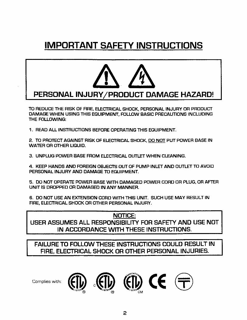
TO REDUCE THE RISK OF. FIRE. ELECTRICAL SHOCK, PERSONAL INJURY OR PRODUCT DAMAGE WHEN USING THIS EQUIPMENT, FOLLOW BASIC PRECAUTIONS INCLUDING THE FOLLOWING:
1. READ ALL INSTRUCTIONS BEFORE OPERATING THIS EQUIPMENT.
2. TO PROTECT AGAINST RISK OF ELECTRICAL SHOCK, DO NOT PUT POWER BASE IN WATER OR OTHER LIQUID.
3. UNPLUG POWER BASE FROM ELECTRICAL OUTLET WHEN CLEANING.
4. KEEP HANDS AND FOREIGN OBJECTS OUT OF PUMP INLET AND OUTLET TO AVOID PERSONAL INJURY AND DAMAGE TO EQUIPMENT.
5. DO NOT OPERATE POWER BASE WITH DAMAGED POWER CORD OR PLUG, OR AFTER UNIT IS DROPPED OR DAMAGED IN ANY MANNER.
6. DO NOT USE AN EXTENSION CORD WITH THIS UNIT. SUCH USE MAY RESULT IN FIRE, ELECTRICAL SHOCK OR OTHER PERSONAL INJURY.
NOTICE: USER ASSUMES ALL RESPONSIBILITY FOR SAFETY AND USE NOT
IN ACCORDANCE WITH THESE INSTRUCTIONS.
FAILURE TO FOLLOW THESE INSTRUCTIONS COULD RESULT IN FIRE, ELECTRICAL SHOCK OR OTHER PERSONAL INJURIES.
complieswith: S. cs. ~j~ (E ~
2
CONTENTS
IMPORTANT SAFETY INSTRUCTIONS................................................................................... 2
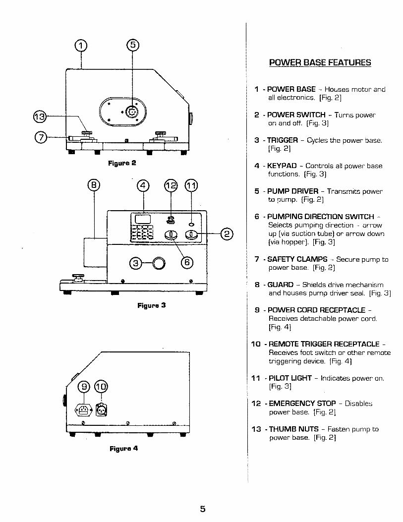
9 - POWER CORD RECEPTACLE -Receives detachable power cord. [Fig. 4]
10 -REMOTE TRIGGER RECEPTACLEReceives foot switch or other remote triggering device. (Fig. 4]
11 - PILOT LIGHT Indicates power on. [Fig. 3]
12 - EMERGENCY STOP - Disables power base. [Fig. 2]
13 -THUMB NUTS Fasten pump to power base. [Fig. 2]
ASSEMBLY AND SETUP
WHEN USING PICKUP TUBE (Fig.1, Page 4)
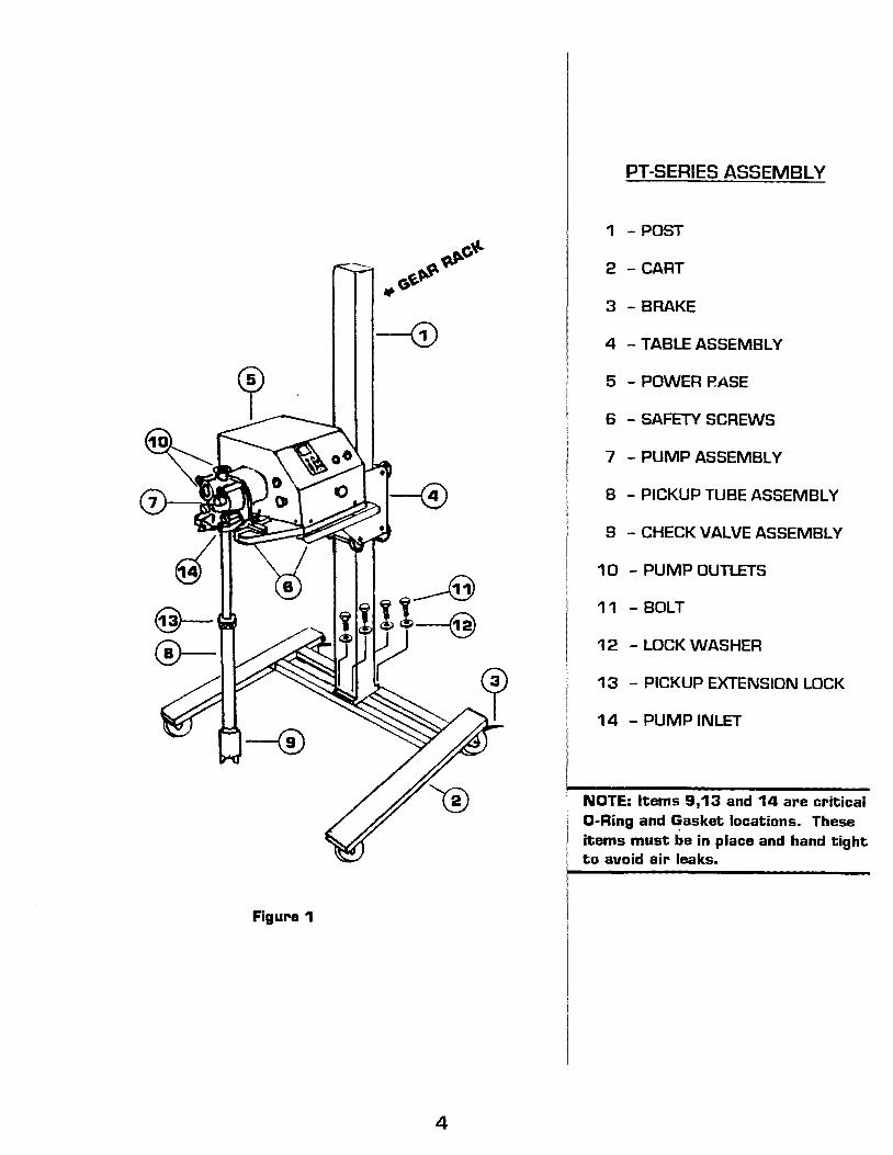
1. Place CART@ [Fig.1, Page 4) ~the floor with wheels down. 2. Lock both rear wheel BRAKES@ [Fig.1). 3. Place POST~on CART~with gear rack faci~ to the rear of cart (Fig.1 ). 4. Secure POST 1 to CART 2 with four BOLTS (!jJ and four LOCKWASHERS @. 5. Place TABLE 4 over POS 1 [Fig.1) and carefully lower TABLE to engage drive gear
with gear rack y rotating the crank handle. Crank table half way down. 6. Place POWER BASE@ (Fig.1) on the TABLE@). Make sure that rubber feet are
seated in the table recesses. 7. Hand tighten both SAFETY SCREWS@ into POWER BASE@ [Fig.1).
WARNING: If power base is going to be used with FT or FTR transfer type pumps A and our ~art PT-801 0 will not be used, the power base must be bolted to a LU sturdy c;able to avoid toppling of the unit.
A) Drill two .28 inch (7mm) diameter holes through table 11.25 inches (285mm) apart and 7 inches (177mm) from the edge of the table. B) Power base should be placed so that the ~four rubber feet are resting on the table. Fasten power base to table from below with two M6x1.0 bolts. Ignoring this warning could result in serious ersonal inju and also cause dama e to the e ui ment.
8. Connect power cord to RECEPTACLE@[Fig.4, Page 5). 9. Plug power cord into a GROUNDED electrical outlet.
1 0. Switch power on using SWITCH@ (Fig.3, Page 5).
A WARNING: DO NOT put fingers in pump openings. Contact with pump impellers LU can cause serious hand injury.
11. Place PUMP ASSEMBL 'C.(?) on POWER BASE@ [Fig.1 ). With left hand~sh pump against PUMP DRIVER~Fig.2J. With the right hand press SEAT KEY@ (Fig.5, Page 8] to engage the pump driver with pump drive shaft. Repeat procedure if necessary until pump is fully ~gaged.
12. Slide both SAFETY CLAMPS\Z) [Fig.2) to engage holes in pump base and tighten knurled nuts.
13. Place D-Ring into the recess of PICKUP TUBE(BlrFig.1) over coarsely threaded end with two tabs. Place steel ball inside CHECK VALVE@[Fig.1). Thread CHECK VALVE ASSEMBLY@ onto PICKUP TUBE@ and hand tiJ!_Qten.
14. Place seal on flange of PICKUP TUBE ASSEMBL Y\.§J and attach to PUMP INLET Qj} with sanitary fitting clamp provided. NOTE: Make sure that all 0-Rings and gaskets are in place on the pickup tube assembly and the joints are hand tight. Air leaks in the pickup assembly will prevent product from being delivered to the pump.
15. Lower table or extend pickup tube so that the CHECK VALVE@[Fig.1] is at the bottom of the product container. Loosen LOCKING NUT @ (Fig.1) on the pickup tube to adjust to desired length, then retighten nut.
16. Prime the pump by filling the vertical PUMP OUTLET @ [Fig.1] with product. 17. Attach your spout or hose to the desired pump outlet and secure it with the supplied
sanitary fitting seal and clamp. The unused pump outlet must be closed with seal, outlet stop and clamp supplied.
6
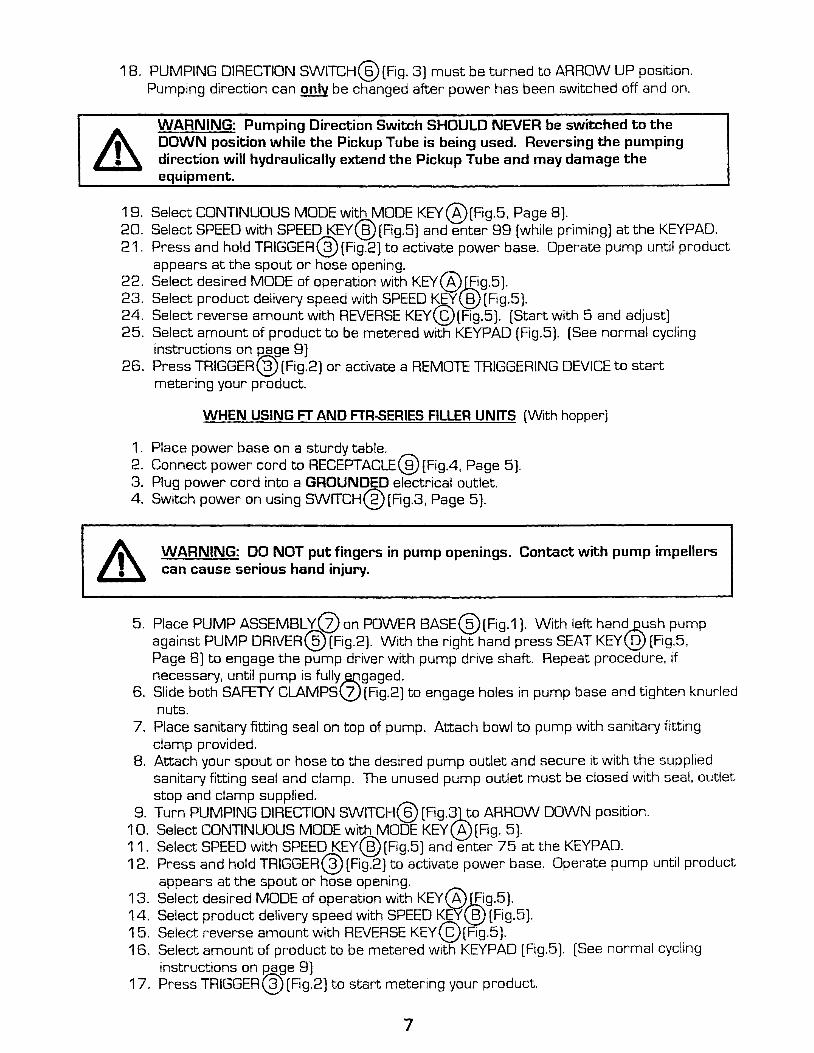
1B. PUMPING DIRECTION SWITCH@ (Fig. 3) must be turned to ARROW UP position. Pumping direction can only be changed after power has been switched off and on.
WARNING: Pumping Direction Switch SHOULD NEVER be switched to the DOWN position while the Pickup Tube is being used. Reversing the pumping direction will hydraulically extend the Pickup Tube and may damage the equipment.
18. Select CONTINUOUS MODE with MODE KEY@[Fig.5, Page B). 20. Select SPEED with SPEED KEY@[Fig.5] and enter 88 [while priming] at the KEYPAD. 21. Press and hold TRIGGER@ (Fig.2) to activate power base. Operate pump until product
appears at the spout or hose opening. 22. Select desired MODE of operation with KEY@Jf!g.5]. 23. Select product delivery speed with SPEED KEY(§) (Fig.5). 24. Select reverse amount with REVERSE KEY@(Fig.5). (Start with 5 and adjust] 25. Select amount of product to be metRred with KEYPAD (Fig.5). (See normal cycling
instructions on Rage 9) 26. Press TRIGGER@[Fig.2] or activate a REMOTE TRIGGERING DEVICE to start
metering your product.
WHEN USING FT AND FTR-SERIES FILLER UNITS [With hopper]
1 . Place power base on a sturdy table. 2. Connect power cord to RECEPTACLE@[Fig.4, Page 5]. 3. Plug power cord into a GROUNDED electrical outlet. 4. Switch power on using SWITCH@[Fig.3, Page 5).
WARNING: DO NOT put fingers in pump openings. Contact with pump impellers can cause serious hand injury.
5. Place PUMP ASSEMBLYQ}on POWER BASE@[Fig.1). With left handgush pump against PUMP DRIVER@ (Fig.2). With the right hand press SEAT KEY@ (Fig.5, Page B) to engage the pump driver with pump drive shaft. Repeat procedure, if necessary, until pump is fully ~gaged.
6. Slide both SAFETY CLAMPS\Z) [Fig.2] to engage holes in pump base and tighten knurled nuts.
7. Place sanitary fitting seal on top of pump. Attach bowl to pump with sanitary fitting clamp provided.
B. Attach your spout or hose to the desired pump outlet and secure it with the supplied sanitary fitting seal and clamp. The unused pump outlet must be closed with seal, outlet stop and clamp supplied.
8. Turn PUMPING DIRECTION SWITCH@ [Fig.3)_!;o ARROW DOWN position. 1 D. Select CONTINUOUS MODE with MODE KEY(6)[Fig. 5). 11. Select SPEED with SPEED KEY@ [Fig.5) and enter 75 at the KEYPAD. . 12. Press and hold TRIGGER@ [Fig.2) to activate power base. Operate pump unt1l product
appears at the spout or hose opening. 13. Select desired MODE of operation with KEY{A)jE!g.5). 14. Select product delivery speed with SPEED KE1(§} [Fig.5). 15. Select reverse amount with REVERSE KEY@[Fig.5]. 16. Select amount of product to be metered with KEYPAD [Fig.5]. (See normal cycling
instructions on Rage 8) 17. Press TRIGGER@[Fig.2] to start metering your product.
7
A-
'
B-
C-
D-
E-
F-
G-
H-
I-
J-
K-
L-
M-
N-
0-
KEYPAD CONFIGURATION AND FUNCTIONS
MODE KEY - Each time this key is pressed, the following functions will be displayed: NORMAL CYCLING, CONTINUOUS RUN, AUTOMATIC CYCLING, RUN TIME and WAITING TIME.
SPEED KEY- When pressed, dispensing speed can be adjusted.
REVERSE KEY - When pressed, the amount of reverse can be adjusted.
SEAT KEY- When pressed, will align pump driver with pump drive shaft.
SPEED SYMBOL - \/\!hen indicated by arrow, speed can be adjusted.
REVERSE SYMBOL - When indicated by arrow, reverse can be adjusted.
NUMBER KEYS - Used to enter number values.
MINUS KEY- When pressed, decreases a number.
PLUS KEY- When pressed, increases a number.
MODE SYMBOL - Shows mode setting. (see Figs.6,7,8,9]
DISPLAY - Shows all values and functions.
ARROWS - When displayed, indicate which function can be adjusted.
RUNNING TIME SYMBOL - When displayed, run time can be changed.
WAITING TIME SYMBOL - When displayed, waiting time can be changed.
ERROR SYMBOL- Er 1 indicates power base overload condition. Er 2 indicates memory module failure. (see Fig.1 0)
~t 25] f1ll2lf3ll~l FIG.11 SPEED
~:r· 25] 11lr2lf3ll~l
FIG.12 REVERSE
8
(! " J
') 25 f1ll2lf3ll~l
FIG.& NORMAL MODE
(! () J , con m f?l m 1 "tll
FIG. 7 CONTINUOUS MODE
! "-+---f--t J
10 m m wl "'(::1 1
FIG.S RUNNING TIME
m m wl "'(::1 1 FIG.9 WAITING TIME
(!
~ Er 1 1-ilf?lr?-\l!"tll FIG.1 0 ERROR
0
USING THE KEYPAD
NORMAL CYCLING
Press MODE [email protected] until MODE SYMBOL'-.. Q) appears as in Fig.6. Enter amount from 1 to 999. Press TRIGGER@ Fig.2 and unit will cycle once, reverse and stop. Experiment with amount settings until desired dispensed quantity is reached.
CONTINUOUS DISPENSING
Press MODE KEY@ Fig.5 until MODE SYMBOL ( J Q) appears as in Fig.7. Instead of a number, the display will show CON. Press TRIGGER@ Fig.2 and hold. Unit will run continuously as long as the trigger is being pressed.
AUTOMATIC CYCLING
This function is used to relieve the operator from repeat~dly cycling the unit manually. It can also be used to deposit product on a moving conveyor. This function consists of two parts RUNNING TIME and WAITING TIME. Press MODE KEY@ Fig.5 until symbols ~' Q)and ~ ~ appear as in Fig.B. Enter desired RUNNING TIME. Press MODE KEY@ again and symbols '"\ Q) and ~@ will appear as in Fig.9. Enter desired WAITING TIME. Press TRIGGE~ @ Fig.2 to start and stop cycling. Note - cycling can be started or stopped while either symbol ~ @ or ~ @ is displayed.
SPEED
Press SPEED KEY@ Fig.5 and an ARROW will point to the symbol ~ Fig.11. To change speed, enter any number between 1 and 99. Speed can also be increased by pressing the PLUS KEY CD Fig.5 or decreased by pressing the MINUS KEY@ Fig.5. Press SPEED KEY @again and display will return to the previously selected mode. Speed can be adjusted with + and - keys while the unit is operating.
REVERSE
Press REVERSE KEY@ Fig.5 and an ARROW will point to the symbol ") Fig.1 Enter the desired reverse value (use lowest value that will prevent dripping) or 0 for no reverse. Press REVERSE KEY@ again and display will return to the previously selected mode.
Place PUMP ASSEMBLY(Z) Fig.1 on the POWER BASE@ Fig.1 and push it up against the PUMP DRIVER@ Fig.2. Press SEAT KEY@ Fig.5 in order to engage the power base drive with the pump drive shaft. Repeat if necessary until the pump is engaged.
ERROR
ERROR SYMBOL@ Fig.1 0 on the display indicates power base overload. This situation occurs when either the product is too viscous or the speed is too high. Switch off power to reset power base. Reduce speed and/ or change viscosity of product.
NOTE: If power is switched off while the unit is cycling, current memory settings will be lost.
9
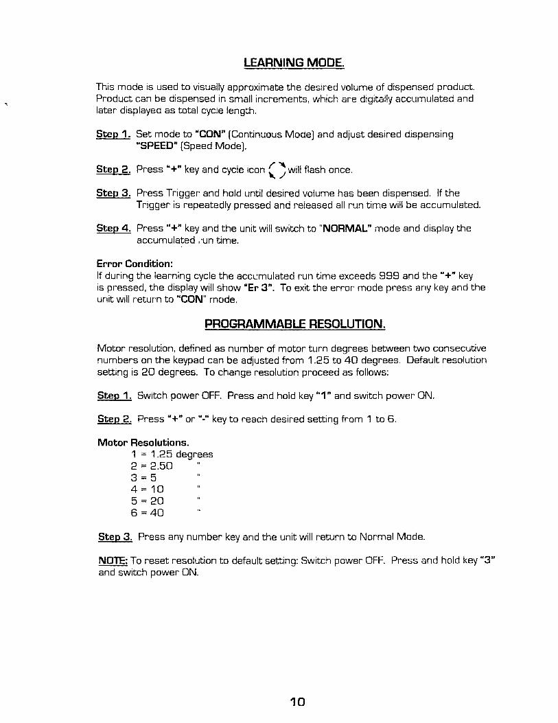
LEARNING MODE.
This mode is used to visually approximate the desired volume of dispensed product. Product can be dispensed in small increments, which are digitally accumulated and later displayed as total cycle length.
Step 1. Set mode to "CON" (Continuous Mode) and adjust desired dispensing "SPEED" (Speed Mode].
Step 3. Press Trigger and hold until desired volume has been dispensed. If the Trigger is repeatedly pressed and released all run time will be accumulated.
Step 4. Press"+" key a11d the unit will switch to "NORMAL" mode and display the accumulated . ·un time.
Error Condition: If during the learning cycle the acc~mulated run time exceeds 999 and the "+" key is pressed, the display will show "Er 3". To exit the error mode press any key and the unit will return to "CON" mode.
PROGRAMMABLE RESOLUTION.
Motor resolution, defined as number of motor turn degrees between two consecutive numbers on the keypad can be adjusted from 1.25 to 40 degrees. Default resolution setting is 20 degrees. To change resolution proceed as follows:
Step 1. Switch power OFF. Press and hold key "1" and switch power ON.
Step 2. Press"+" or"." key to reach desired setting from 1 to 6.
Step 3. Press any number key and the unit will return to Normal Mode.
NOTE: To reset resolution to default setting: Switch power OFF. Press and hold key "3" and switch power ON.
10
CLEANING
POWER BASE
& WARNING: To protect against electrical shock, unplug power base from electrical outlet. DO NOT PLACE POWER BASE IN WATER OR ANY OTHER LIQUID!
Clean exterior of power base using a DAMP CLOTH ONL V!
PUMPS AND FILLER UNITS
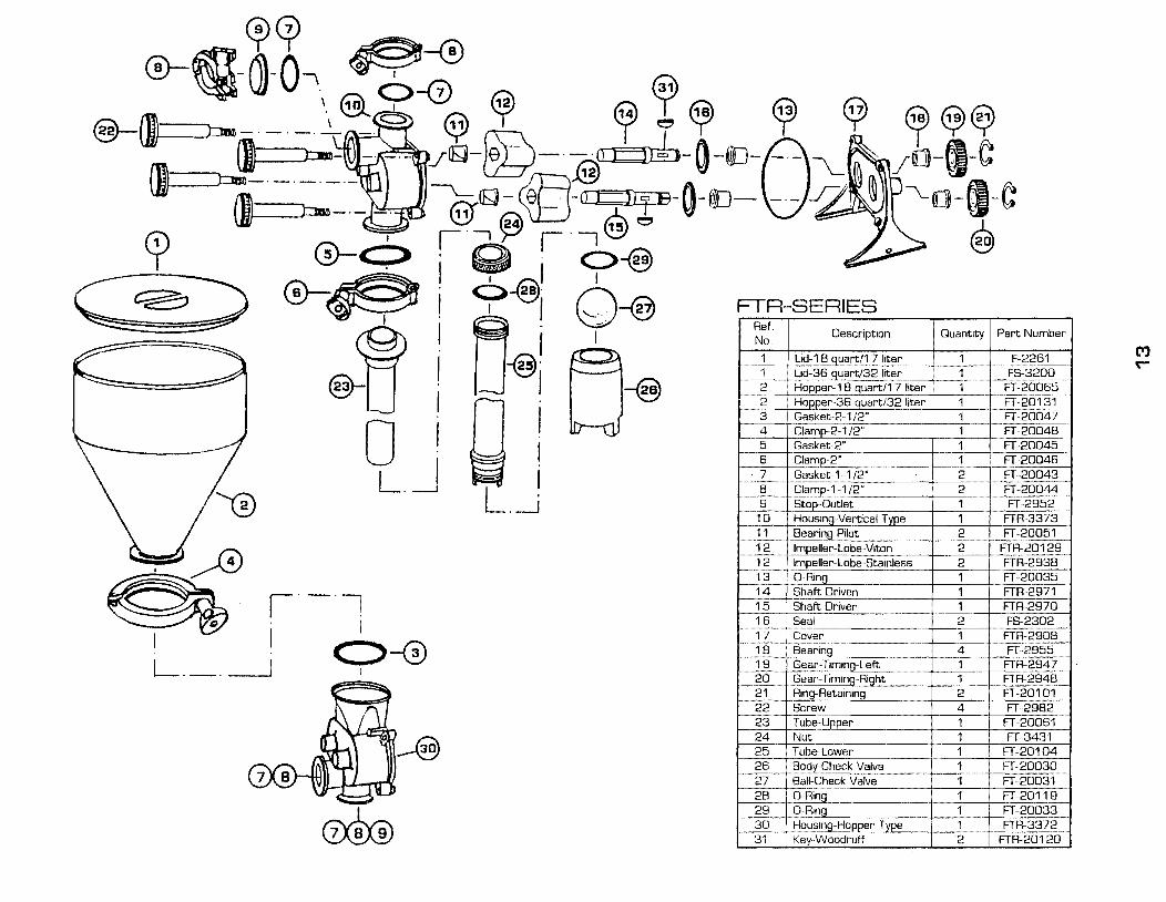
Unclamp bowl or pickup tube and remove spout or hose from pump assembly as applicable. To disassemble pump assembly, remove four thumb screws. Remove pump housing from pump cover. Slide off impeller(s] and remove all pilot bearings (3 in FT and 2 in FTR), GRings, seals and clamps. All stainless steel parts are dishwasher-safe and may be sterilized. All other parts should be hand washed only. Reassemble pump making sure that all bearings are seated properly with their keys in the keyways and any GRings seated completely in their grooves.
A\. WARNING: All pilot bearings must be in place before pump is operated. If this £ll warning is ignored, severe damage to the pump will result.
THUMB &:REW HOUSING
IMPEU..ER COVER ASSY. I GRING J
OJ) hm-·-·-~. PILOT BEARING
MAINTENANCE
POWER BASE
The power base is maintenance free.
PUMPS AND FILLER UNITS
Pumps and filler units have shaft bearings, seals and pilot bearings, which must be replaced when wear or leakage is evident. To replace worn seals:
1 . Using the pointed end of the seal replacement tool, pry out the worn seal. Be careful not to damage the SHAFT SEALING SURFACE. Scratches on this surface will shorten seal life.
2. Clean seal cavity so it is free of all foreign material. Apply suitable lubricant to the INSIDE DIAMETER OF SEAL ONLY.
SHAFT
RETAINING EDGE
I MARK {DOWN)
3. Slide new seal over shaft with reference mark facing DOWN. With your fingers, press the seal into the seal cavity. Using the blunt end of the tool, push the seal all the way down until it is seated below the RETAINING EDGE.
4. Remove and replace worn pilot bearings, making sure that their keys are seated in their keyways.