108
Products Solutions Services BA00330F/00/EN/15.15 71298585 Valid as of software version: 01.03.08 Operating Instructions Gammapilot M FMG60 Radiometric Measurement
| Date post: | 14-Dec-2018 |
| Category: |
Documents |
| Upload: | trinhduong |
| View: | 226 times |
| Download: | 0 times |

Products Solutions ServicesBA00330F/00/EN/15.1571298585
Valid as of software version: 01.03.08
Operating InstructionsGammapilot M FMG60Radiometric Measurement

Endress+Hauser
Brief operating instructions
L00-FMG60xxx-05-00-00-en-050
Contents of the Operating InstructionsThese Operating Instructions describe how to install and commission the radiometric compact transmitter Gammapilot M (communication version FOUNDATION Fieldbus). All the functions that are required for standard measuring tasks have been included. Also, the Gammapilot M provides additional functions for optimizing the measuring point and for converting the measured value. These functions are not included in these Operating Instructions.
You can find an overview of all the device functions in the Appendix.
A detailed description of all the instrument functions is given in Operating Instructions BA00287F/00/EN "Gammapilot M - Description of Device Functions" which can be found on the CD-ROM supplied.
E+-
+
E+-
-… …
… …
100 (HART)2457 (PA,FF)
333 (HART)33333 (PA,FF)
…
… …
E
E
E
E
52025626
KA242F/00/a2/02.07
*00
*0
*2
*C
*4
*5
*6
*A *A0
*01 *02 *03 *04 *06 *09 *0A *0B
*A1 *A4
*3
*9 *92
*A3
*C0
*05
*1 *10 *11 *12 *13
*14 *16*15 *11
*19
*17 *18*15 *11
*1B*11 *1C *1D *1E *1F*1A *15 *19
++
*07 *08
slave, end slave
safety settings
systemparameters
linearisation
gammagraphy
output (HART, FF)profibus param.(PA)
diagnostics presenterror
previouserror
unlockparameter
temp. compens.
display language
reset
tagmarking
density/concentration
densitycalibr.
stop/edit
startavg. pulserate
densityvalue
calibr.point
absorp.coeff.
ref. pulserate
calibr.point
calibration next pointno
yes
Contrast: or
*indicates themeas.mode:L: LevelS: Level limitD: DensityC: Concentration
calibration backgr.calib
startavg. pulserate
bgr. pulserate
stop/edit
calibr. point
valuefull
fullcalibr.
stop/edit
calibrationstart
avg. pulserate
next point
valueempty
emptycalibr.
stop/edit
calibrationstart
avg. pulserate
no
yes
level/limit
densityunit
pipe diam.unit
pipe diam. outputdamping
min.density
max.density
measured value
Groupselection
basic setup todaysdate
beam type isotope operatingmode
meas.mode
Gammapilot M - Quick Setup

Gammapilot M FMG60 FOUNDATION Fieldbus
Endress+Hauser 3
Table of contents
1 Safety instructions . . . . . . . . . . . . . . . . . . 41.1 Designated use . . . . . . . . . . . . . . . . . . . . . . . . . . . . . 41.2 Installation, commissioning, operation . . . . . . . . . 41.3 Hazardous area . . . . . . . . . . . . . . . . . . . . . . . . . . . . . 41.4 Radiation protection . . . . . . . . . . . . . . . . . . . . . . . . . 51.5 Symbols . . . . . . . . . . . . . . . . . . . . . . . . . . . . . . . . . . . 6
2 Identification . . . . . . . . . . . . . . . . . . . . . . 82.1 Parts of the Gammapilot M . . . . . . . . . . . . . . . . . . . 82.2 Nameplates . . . . . . . . . . . . . . . . . . . . . . . . . . . . . . . . 92.3 Scope of delivery . . . . . . . . . . . . . . . . . . . . . . . . . . . . 92.4 Supplied documentation . . . . . . . . . . . . . . . . . . . 102.5 Certificates and approvals . . . . . . . . . . . . . . . . . . 102.6 Registered trademarks . . . . . . . . . . . . . . . . . . . . . 10
3 Installation . . . . . . . . . . . . . . . . . . . . . . . 113.1 Incoming acceptance, transport, storage . . . . . . 113.2 Installation conditions . . . . . . . . . . . . . . . . . . . . . 123.3 Water cooling . . . . . . . . . . . . . . . . . . . . . . . . . . . . 173.4 Installation check . . . . . . . . . . . . . . . . . . . . . . . . . 19
4 Wiring . . . . . . . . . . . . . . . . . . . . . . . . . . . 204.1 Terminal compartments . . . . . . . . . . . . . . . . . . . . 204.2 Cable entries . . . . . . . . . . . . . . . . . . . . . . . . . . . . . 204.3 Terminal assignment . . . . . . . . . . . . . . . . . . . . . . 214.4 Fieldbus connectors . . . . . . . . . . . . . . . . . . . . . . . 234.5 Foundation Fieldbus cable specifications . . . . . . 244.6 Foundation Fieldbus terminal voltage . . . . . . . 244.7 Potential equalization . . . . . . . . . . . . . . . . . . . . . . 244.8 Wiring in terminal compartment 1 . . . . . . . . . . 254.9 Wiring in terminal compartment 2 . . . . . . . . . . 264.10 Connecting the
remote display and operation FHX40 . . . . . . . . . 274.11 Wiring in cascading mode . . . . . . . . . . . . . . . . . . 284.12 Measuring solids flow . . . . . . . . . . . . . . . . . . . . . . 294.13 Post-connection check . . . . . . . . . . . . . . . . . . . . . 29
5 Operation. . . . . . . . . . . . . . . . . . . . . . . . . 305.1 Overview over the operating options . . . . . . . . . 305.2 Display operation . . . . . . . . . . . . . . . . . . . . . . . . . 315.3 Alternative operation options . . . . . . . . . . . . . . . 355.4 Lock/unlock configuration . . . . . . . . . . . . . . . . . . 365.5 Reset to the default configuration . . . . . . . . . . . 365.6 FOUNDATION Fieldbus interface . . . . . . . . . . . . 37
6 Commissioning. . . . . . . . . . . . . . . . . . . . 546.1 Calibration: overview . . . . . . . . . . . . . . . . . . . . . . 546.2 Switching on the device . . . . . . . . . . . . . . . . . . . . 596.3 Basic setup . . . . . . . . . . . . . . . . . . . . . . . . . . . . . . . 606.4 Calibration for
level measurement and limit detection . . . . . . . 66
6.5 Calibration for density and concentration measurements . . . . . . . . . . . . . . . . . . . . . . . . . . . . 75
6.6 Density measurement/temperature-compensated . . . . . . . . . . . . . . . . . . 83
6.7 Gammagraphy detection . . . . . . . . . . . . . . . . . . . . 83
7 Maintenance and repairs. . . . . . . . . . . 847.1 Exterior cleaning . . . . . . . . . . . . . . . . . . . . . . . . . . . 847.2 Repair . . . . . . . . . . . . . . . . . . . . . . . . . . . . . . . . . . . . 847.3 Repairs to Ex-approved devices . . . . . . . . . . . . . . 847.4 Replacement . . . . . . . . . . . . . . . . . . . . . . . . . . . . . . 847.5 Return . . . . . . . . . . . . . . . . . . . . . . . . . . . . . . . . . . . 857.6 Disposal . . . . . . . . . . . . . . . . . . . . . . . . . . . . . . . . . . 857.7 Contact addresses of Endress+Hauser . . . . . . . . . 85
8 Accessories. . . . . . . . . . . . . . . . . . . . . . . 868.1 Commubox FXA291 . . . . . . . . . . . . . . . . . . . . . . . . 868.2 ToF adapter FXA291 . . . . . . . . . . . . . . . . . . . . . . . 868.3 Field Xpert SFX100 . . . . . . . . . . . . . . . . . . . . . . . . . 868.4 Remote display FHX40 . . . . . . . . . . . . . . . . . . . . . . 878.5 Mounting device FHG60 (for level
measurement and level limit measurement) . . . 898.6 Clamping device for
density measurement FHG61 . . . . . . . . . . . . . . . . 918.7 Measurement section for
density measurement FHG62 . . . . . . . . . . . . . . . . 91
9 Troubleshooting . . . . . . . . . . . . . . . . . . 929.1 System error messages . . . . . . . . . . . . . . . . . . . . . 929.2 Possible calibration errors . . . . . . . . . . . . . . . . . . . 959.3 Software history . . . . . . . . . . . . . . . . . . . . . . . . . . . 95
10 Technical data . . . . . . . . . . . . . . . . . . . . 9610.1 Additional technical data . . . . . . . . . . . . . . . . . . . . 9610.2 Documentation . . . . . . . . . . . . . . . . . . . . . . . . . . . . 96
11 Appendix . . . . . . . . . . . . . . . . . . . . . . . 10011.1 Operating menu for level measurements . . . . 10011.2 Operating menu for level limit detection . . . . . 10211.3 Operating menu for density and concentration
measurements . . . . . . . . . . . . . . . . . . . . . . . . . . 104
Index . . . . . . . . . . . . . . . . . . . . . . . . . . . 106

Safety instructions Gammapilot M FMG60 FOUNDATION Fieldbus
4 Endress+Hauser
1 Safety instructions
1.1 Designated useThe Gammapilot M is a compact transmitter for non-contact level, level limit, density and concentration measurement. The measuring range of a single Gammapilot M extends up to 2 m (6.6 ft). Large measuring ranges of any size can be implemented, however, by cascading several Gammapilot M devices.
1.2 Installation, commissioning, operationThe Gammapilot M is fail-safe and is constructed to the state-of-the-art. It meets the appropriate standards and EC directives. However, if you use it improperly or other than for its designated use, it may pose application-specific hazards, e.g. product overflow due to incorrect installation or configuration. Installation, electrical connection, startup, operation and maintenance of the measuring device must therefore be carried out exclusively by trained specialists authorized by the system operator. Technical personnel must have read and understood these Operating Instructions and must adhere to them. You may only undertake modifications or repair work to the device when it is expressly permitted by the Operating Instructions.
1.3 Hazardous areaMeasuring systems for use in hazardous environments are accompanied by separate "Ex documentation", which is an integral part of these Operating Instructions. Strict compliance with the installation instructions and ratings as stated in this supplementary documentation is mandatory.
• Ensure that all personnel are suitably qualified.• Observe the specifications in the certificate as well as national and local standards and
regulations.
CAUTION!
Detector or cooling jacket can be damaged if the cooling water freezes.‣ Empty cooling jacket or protect against freezing.
WARNING!
Depending on the certificate version observe the associated Safety Instructions ( ä 96).
WARNING!
The three screws, connecting the pipe housing to the compartment housing, must not be opened.
A0018068

Gammapilot M FMG60 FOUNDATION Fieldbus Safety instructions
Endress+Hauser 5
1.4 Radiation protectionThe Gammapilot M is used in conjunction with a radioactive source, contained in a source container. When handling radioactive sources, the following instructions have to be observed:
1.4.1 Basic regulations on radiation protection
WARNING!
When handling radioactive sources, all unnecessary radiation exposure should be avoided. All unavoidable radiation exposure should be kept as low as possible. Three measures are used for this:
A0016373
A ScreeningB TimeC Distance
Shielding
Ensure the best possible shielding between the radiation source and yourself as well as all other individuals. Effective shielding is provided by source containers (FQG60, FQG61/ FQG62, FQG63, QG2000) and all high-density materials (lead, iron, concrete).
CAUTION!
When working with source containers, all the instructions for mounting and usage outlined in the following documents must be observed:
Time
Stay as short as possible in the area exposed to radiation.
Distance
Keep as far away as possible from the radiation source. The local radiation intensity decreases as the square-root of the distance from the radiation source.
A B C
Source Container Document
FQG60 TI00445F/00/EN
FQG61, FQG62 TI00435F/00/EN
FQG63 TI00446F/00/EN
QG2000 TI00346F/00/ENBA00223F/00/EN

Safety instructions Gammapilot M FMG60 FOUNDATION Fieldbus
6 Endress+Hauser
1.5 Symbols
1.5.1 Safety symbols
1.5.2 Electrical symbols
1.5.3 Tool symbols
Symbol Meaning
A0011189-DE
DANGER!This symbol alerts you to a dangerous situation. Failure to avoid this situation will result in serious or fatal injury.
A0011190-DE
WARNING!This symbol alerts you to a dangerous situation. Failure to avoid this situation can result in serious or fatal injury.
A0011191-DE
CAUTION!This symbol alerts you to a dangerous situation. Failure to avoid this situation can result in minor or medium injury.
A0011192-DE
NOTICE!This symbol contains information on procedures and other facts which do not result in personal injury.
Symbol Meaning
A0018338
Ground connectionA grounded terminal which, as far as the operator is concerned, is grounded via a grounding system..
A0018339
Protective ground connectionA terminal which must be connected to ground prior to establishing any other connections.
Symbol Meaning
A0011221
Allen key
DANGER
WARNING
CAUTION
NOTICE
Gammapilot M FMG60 FOUNDATION Fieldbus Safety instructions
Endress+Hauser 7
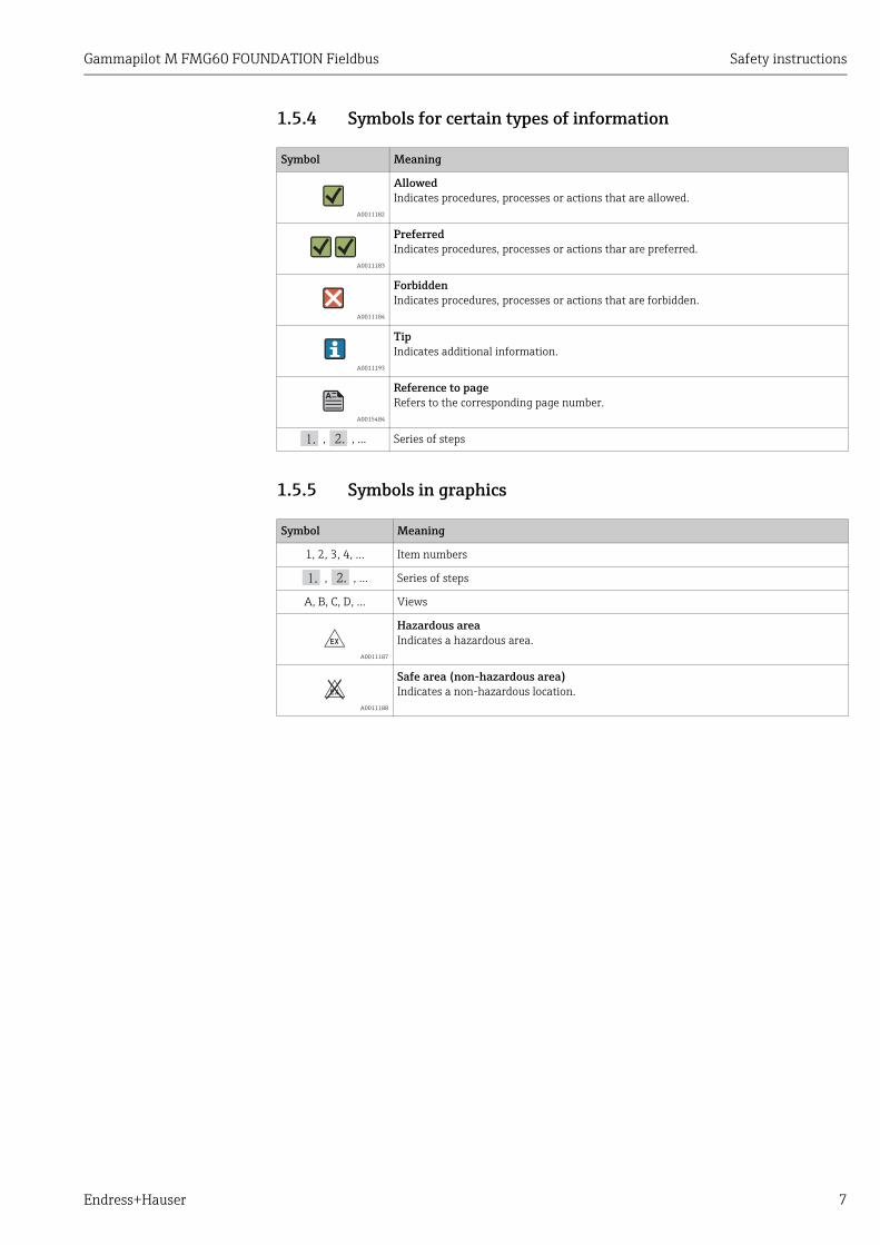
1.5.4 Symbols for certain types of information
1.5.5 Symbols in graphics
Symbol Meaning
A0011182
AllowedIndicates procedures, processes or actions that are allowed.
A0011183
PreferredIndicates procedures, processes or actions thar are preferred.
A0011184
ForbiddenIndicates procedures, processes or actions that are forbidden.
A0011193
TipIndicates additional information.
A0015484
Reference to pageRefers to the corresponding page number.
, , ... Series of steps
Symbol Meaning
1, 2, 3, 4, ... Item numbers
, , ... Series of steps
A, B, C, D, ... Views
A0011187
Hazardous areaIndicates a hazardous area.
A0011188
Safe area (non-hazardous area)Indicates a non-hazardous location.
-
.

Identification Gammapilot M FMG60 FOUNDATION Fieldbus
8 Endress+Hauser
2 Identification
2.1 Parts of the Gammapilot M
1. Terminal head
2. Mounting collar
3. Detector pipe
4. Measuring range marks
5. Terminal compartment B
6. Terminal compartment A
7. Supplementary nameplate
8. Centering knob
9. Instrument nameplate
10. Cooling water connections
11. Marking of the radiation window (only for versions with collimator)
12. Potential equalization terminal of the water cooling jacket
A0018069
A Gammapilot M without water cooling jacketB Gammapilot M with water cooling jacketC Gammapilot M with collimator
1
2
3
6
5
8
4
4
9
7
4
4
10
10
A B/C
12
11
C

Gammapilot M FMG60 FOUNDATION Fieldbus Identification
Endress+Hauser 9
2.2 Nameplates
2.3 Scope of delivery• Ordered version of the device (including Operating Instructions)• Endress+Hauser operating program (on the CD-ROM supplied)• Accessories as ordered
Device nameplate
A0018070
1 Order code (as defined by the Ordering information)2 Serial number3 Measuring range4 Power supply5 Output signal6 Max. ambient temperature
Supplementary nameplate (Examples)
A0018070
7 No. of certificate8 Equipment group and category9 Type of protection
10 Reference to additional safety-relevant information11 Reference to additional certificates (e.g. WHG, SIL)12 Specification of required temperature resistance of
the connected cables (only for instrument versions with water cooling jacket)
Ser.-No.:
Order Code:
IP 66/67
Gammapilot M
Made in Germany, D-79689 Maulburg
L= mm
Dat. xx.xx 25
00
01
82
8-
-
TYPE 4X / 6 Encl.
Ta-40°C °C
12
3
4
56
00
00
00
--
KEMA 04 ATEX
11
10
78 9
00
00
00
--
11
10
T Ta + 20 K
T Ta + 20 K
0044

Identification Gammapilot M FMG60 FOUNDATION Fieldbus
10 Endress+Hauser
2.4 Supplied documentation
2.4.1 Operating Instructions (BA00330F/00/EN)Describe how to install and commission the Gammapilot M (communication version FOUNDATION Fieldbus). Those functions of the operating menu are included, which are required for standard measuring tasks. Any additional functions are contained in the "Description of Device Functions" (BA00287F/00/EN).
2.4.2 Description of Device Functions (BA00287F/00/EN)Contains a detailed description of all the functions of the Gammapilot M and applies for all communication versions. This document can be found as a PDF file on the CD-ROM supplied and can be downloaded from the Internet under "www.de.endress.com" ( download).
2.4.3 Safety instructionsAdditional safety instructions (XA, ZE, ZD) are supplied with certified device versions. Refer to the nameplate for the names of the safety instructions that apply to your device variant.An overview of the certificates and approvals can be found in TI00363F/00/EN, chapter "Certificates and approvals".
2.5 Certificates and approvalsCE mark, declaration of conformityThe device is designed to meet state-of-the-art safety requirements, has been tested and left the factory in a condition in which it is safe to operate. The device takes into account applicable standards and regulations which are listed in the EC declaration of conformity and thus meets the legal requirements of the EC Directives. Endress+Hauser confirms the successful testing of the device by affixing to it the CE mark.
2.6 Registered trademarksFOUNDATION™ FieldbusRegistered trademark of the Fieldbus Foundation Austin, Texas, USA
ToF®
Registered trademark of Endress+Hauser GmbH+Co. KG, Maulburg, Germany

Gammapilot M FMG60 FOUNDATION Fieldbus Installation
Endress+Hauser 11
3 Installation
3.1 Incoming acceptance, transport, storage
3.1.1 Incoming acceptanceCheck the packing and contents for any signs of damage.Check the shipment, make sure nothing is missing and that the scope of supply matches your order.
3.1.2 Transport
CAUTION!
Follow the safety instructions and transport conditions for devices of more than 18 kg (39.69 lbs).
3.1.3 StoragePack the measuring device so that it is protected against impacts for storage and transport. The original packing material provides the optimum protection for this. The permissible storage temperature is:• -40 to +50 °C (-40 to +122 °F) for devices with PVT scintillator• -40 to +60 °C (-40 to +140 °F) for devices with NaI crystal

Installation Gammapilot M FMG60 FOUNDATION Fieldbus
12 Endress+Hauser
3.2 Installation conditions
3.2.1 Dimensions, weight
Gammapilot M (without water cooling jacket)
A0018072
Gammapilot M with water cooling jacket or collimator
A0018073
TypeMeasuring
length A [mm (in)]
Without water cooling jacket
With water cooling jacket
Overall length
B [mm (in)]
Weight [kg (lbs)]1)
1) The given weight data are for 316L version. The weight of the aluminium version is reduced by 5,3 kg (11.69 lbs).
Overall length
B [mm (in)]
Weightwithout water
[kg (lbs)])
Weightincluding
water[kg (lbs)])
NaI 50 (1.97) 621 (24.4) 14 (30.87) 631 (24.8) 18 (39.69) 20 (44.10)
NaI with collimator 50 (1.97) 663 (26.1) 35 (77.18)
PVT 200 (7.87) 780 (30.7) 15 (33.08) 790 (31.1) 20 (44.10) 24 (52.92)
PVT 400 (15.7) 980 (38.6) 16 (35.28) 990 (39) 23 (50.72) 29 (63.95)
PVT 800 (31.5) 1380 (54.3) 20 (44.10) 1390 (54.7) 31 (68.36) 40 (88.20)
PVT 1200 (47.5) 1780 (70.1) 24 (52.92) 1790 (70.5) 37 (81.59) 50 (110.25)
PVT 1600 (63) 2180 (85.8) 28 (61.74) 2190 (86.2) 45 (99.23) 61 (134.51)
PVT 2000 (7.87) 2580 (102) 31 (68.36) 2590 (102) 51 (112.46) 72 (158.76)
16
0x1
90
(6.3
x7
.48
)
ø1
20
(4.7
2)
ø8
0
(3.1
5)537 (22.6)
mm (in)
A
B1
60
x1
90
(6.3
x7
.48
)
537 (22.6) A
B
164 (6.46)
mm (in)
12 (0.47)
ø1
40
(5.5
1)

Gammapilot M FMG60 FOUNDATION Fieldbus Installation
Endress+Hauser 13
3.2.2 Installation conditions for level measurement
Conditions
• For level measurements the Gammapilot M is mounted vertically; if possible the detector head should point downwards.
• The exit angle of the source container must be exactly aligned to the measuring range of the Gammapilot M. Observe the measuring range marks of the Gammapilot M.
• In cascading mode no gap should occur between the measuring ranges of the different Gammapilot M.
• The source container and the Gammapilot M must be mounted as close to the vessel as possible. Any access to the beam must be blocked so that no persons or part of their body (hand, arm, head) may come into the area of the beam.
• In order to enlarge the lifetime, the Gammapilot M should be protected against direct sun. If necessary, a protective cover should be applied.
• The mounting device FHG60 ( ä 86, "Accessories") or an equivalent mounting device should be used for fastening the Gammapilot M.The mounting device must be installed in a way such that it can withstand the weight of the Gammapilot M1) under all operating conditions (e.g. vibrations).
NOTICEThe Gammapilot M should be given additional support to prevent damage to the connecting cable or to the unit if it falls off.
Examples
A0018074
A Vertical cylinder; the Gammapilot M is mounted vertically with the detector head pointing downwards; the gamma ray is aligned to the measuring range.
B Cascading of multiple Gammapilot M; there is no gap between the measuring rangesC Wrong: Gammapilot M mounted inside the tank insulationD Conical tank outlet (here with sun protection cover)E Horizontal cylinder (here with sun protection cover)F Right: Tank insulation removed for Gammapilot M
1 Support
1) The weights of the various versions of the Gammapilot M are summarized in the section "Dimensions/Weight".
A
D
B C
E F1

Installation Gammapilot M FMG60 FOUNDATION Fieldbus
14 Endress+Hauser
3.2.3 Installation conditions for level limit detection
Conditions
• For level limit detection, the Gammapilot M should be mounted horizontally at the height of the desired level limit.
• The exit angle of the source container must be exactly aligned to the measuring range of the Gammapilot M. Observe the measuring range marks of the Gammapilot M.
• The source container and the Gammapilot M must be mounted as close to the vessel as possible. Any access to the beam must be blocked so that no persons or part of their body (hand, arm, head) may come into the area of the beam.
• In order to enlarge the lifetime, the Gammapilot M should be protected against direct sun. If necessary, a protective cover should be applied.
• The mounting device FHG60 ( ä 86, "Accessories") or an equivalent mounting device should be used for fastening the Gammapilot M.The mounting device itself must be fitted in a way such that it can withstand the weight of the Gammapilot M2) under all operating conditions to be expected.
Examples
A0018075
A Maximum fail-safe modeB Minimum point level detection
2) The weights of the various versions of the Gammapilot M are summarized in the section "Dimensions/Weight".
A B

Gammapilot M FMG60 FOUNDATION Fieldbus Installation
Endress+Hauser 15
3.2.4 Installation conditions for density and concentration measurement
Conditions
• If possible, density and concentration should be measured at vertical pipes with a feed direction from bottom to top.
• If only horizontal pipes are accessible, the path of the ray should also be arranged horizontally to reduce the influence of air bubbles and sediments.
• The Endress+Hauser clamping device ( ä 86, "Accessories") or an equivalent clamping device should be used for fastening the radiation source container and the Gammapilot M to the measuring tube. The clamping device itself must be installed in a way such that it can withstand the weight of the source container3) and the Gammapilot M4) under all operating conditions.
• The sample point may not be further than 20 m (66 ft) from the measuring point. • The distance of the density measurement to pipe bends is 3 x pipe diameter and 10 x
pipe diameter for pumps.
Configuration of the measuring system
The configuration of the source container and the Gammapilot M depends on the pipe diameter (or the length of the irradiated measuring path respectively) and the measuring range. These two parameters determine the measuring effect (relative change of the pulse rate). The measuring effect increases with the length of the radiation path through the medium. Therefore, diagonal irradiation or the use of a measurement section is necessary for small pipe diameters.
For the configuration of the measuring system please contact your Endress+Hauser sales organization or use the "Applicator" 5) configuration software.
A0018076
A Vertical beam (90°)B Diagonal beam (30°)C Measurement section1 Sample point
NOTICEGeneral‣ To increase the accuracy for density measurements, the use of a collimator is
recommended. The collimator screens the detector against environmental radiation.‣ When planning, the total weight of the measuring system must be taken into
consideration.‣ The Gammapilot M should be given additional support to secure it against falling or
prevent damage to the connecting cable. ‣ A clamping device and a measurement section are available as accessories ( ä 86,
"Accessories").
3) The weights of the source containers are specified in TI00445F/00/EN (FQG60), TI00435F/00/EN (FQG61, FQG62), TI00446F/00/EN (FQG63) or TI00346F/00/EN (QG2000).
4) The weights of the various versions of the Gammapilot M are summarized in the section "Dimensions, weight".5) The "Applicator" is available from your Endress+Hauser sales organization.
A B C
1

Installation Gammapilot M FMG60 FOUNDATION Fieldbus
16 Endress+Hauser
3.2.5 Empty pipe detection
A0018077
1 Gammapilot M2 Monitoring detector FTG20 or FMG603 SPS
Mounting the FTG20 or FMG60 on the FMG60 for empty pipe detection
If the pipe becomes empty as a result of operational processes, the radiation on the detector side can hit dangerous levels.• In such instances, the irradiation channel must be closed immediately for reasons of
radiation protection.• A high local dose rate also causes the detector unit (scintillator and photomultiplier) to age
quickly.
The best way of avoiding such a situation is to mount a second radiometric measuring system that monitors the radiation intensity. If high radiation levels occur, an alarm is output and/or the source container is automatically switched off through pneumatic action for example.
1
2
3

Gammapilot M FMG60 FOUNDATION Fieldbus Installation
Endress+Hauser 17
3.3 Water coolingFor the versions of the Gammapilot with water cooling jacket, the following applies:• Material: 316L• Water connection: 2 x G 1/4"A, DIN ISO 228• Inlet temperature: max. 40 °C (104 °F)• Outlet temperature: max. 50 °C (122 °F)(temperature monitoring recommended)• Water pressure: 4 to 6 bar (60 to 90 psi)
A0018078
A T <75 °C (167 °F)B T <120 °C (248 °F)
CAUTION!
Detector or cooling jacket can be damaged if the cooling water freezes.‣ Empty cooling jacket or protect against freezing.
WARNING!
Pressurized water cooling system!‣ Do not open the cylinder screws (see figure below) when pressurized.
A0023205
1 Cylinder screws
A B
G1/4"AG1/4"A
*
1
CAUTION!
To consider when using the water cooling jacket‣ It is recommended to ground the water
cooling jacket separately at the provided earth terminal (see picture above)
‣ The ambient temperature of the compartment housing must not exceed 75 °C (167 °F). This is also valid, if water cooling is applied.
‣ The three screws, connecting the pipe housing to the compartment housing, must not be opened.
A0018068

Installation Gammapilot M FMG60 FOUNDATION Fieldbus
18 Endress+Hauser
3.3.1 Mounting versions
A0018079
A Recommended mounting position for level measurement: compartment housing at the bottomB In exceptional cases (e.g. shortage of space) the compartment housing may be located at the topC Mounting position for point level detection and density measurement
CAUTION!
The water inlet must always be at the bottom to ensure that the water cooling jacket is completely filled.
A B C

Gammapilot M FMG60 FOUNDATION Fieldbus Installation
Endress+Hauser 19
3.3.2 Required flow rateThe required flow rate depends on• the ambient temperature at the water cooling jacket• the inlet temperature• the measuring range of the Gammapilot M
Typical values are given in the following tables:
Ambient temperature TA = 75 °C (167 °F)
Ambient temperature TA = 100 °C (212 °F)
Ambient temperature TA = 120 °C (248 °F)
3.4 Installation checkAfter installing the device, carry out the following checks:• Is the device damaged (visual inspection)?• Does the device correspond to the measuring point specifications for ambient
temperature, measuring range etc.?• If available: Are the measuring point number and labeling correct (visual inspection)?• Is the measuring device sufficiently protected against direct sunlight?• Are the cable glands tightened correctly?
Inlet temperature°C (°F)
Measuring range in mm (in)
50 (1.97) 200 (7.87) 400 (15.7) 800 (31.5) 1200 (47.2)
1600 (63) 2000 (78.7)
20 (68) 30 l/h 30 l/h 30 l/h 41 l/h 55 l/h 70 l/h 84 l/h
25 (77) 30 l/h 30 l/h 30 l/h 45 l/h 61 l/h 77 l/h 93 l/h
30 (86) 30 l/h 30 l/h 33 l/h 50 l/h 68 l/h 86 l/h 104 l/h
35 (95) 30 l/h 30 l/h 38 l/h 59 l/h 80 l/h 101 l/h 122 l/h
40 (104) 30 l/h 30 l/h 47 l/h 72 l/h 98 l/h 124 l/h 149 l/h
Inlet temperature°C (°F)
Measuring range in mm (in)
50 (1.97) 200 (7.87) 400 (15.7) 800 (31.5) 1200 (47.2)
1600 (63) 2000 (78.7)
20 (68) 30 l/h 30 l/h 38 l/h 59 l/h 80 l/h 101 l/h 122 l/h
25 (77) 30 l/h 30 l/h 42 l/h 64 l/h 87 l/h 110 l/h 133 l/h
30 (86) 30 l/h 30 l/h 47 l/h 73 l/h 98 l/h 124 l/h 150 l/h
35 (95) 30 l/h 30 l/h 54 l/h 84 l/h 113 l/h 143 l/h 173 l/h
40 (104) 33 l/h 33 l/h 66 l/h 101 l/h 137 l/h 173 l/h 210 l/h
Inlet temperature°C (°F)
Measuring range in mm (in)
50 (1.97) 200 (7.87) 400 (15.7) 800 (31.5) 1200 (47.2) 1600 (63) 2000 (78.7)
20 (68) 30 l/h 30 l/h 45 l/h 70 l/h 94 l/h 119 l/h 144 l/h
25 (77) 30 l/h 30 l/h 50 l/h 77 l/h 104 l/h 131 l/h 158 l/h
30 (86) 30 l/h 30 l/h 55 l/h 85 l/h 115 l/h 146 l/h 176 l/h
35 (95) 32 l/h 32 l/h 64 l/h 98 l/h 133 l/h 168 l/h 203 l/h
40 (104) 38 l/h 38 l/h 75 l/h 116 l/h 157 l/h 199 l/h 240 l/h

Wiring Gammapilot M FMG60 FOUNDATION Fieldbus
20 Endress+Hauser
4 Wiring
4.1 Terminal compartments
4.2 Cable entries
NOTICECable entries‣ On delivery, not more than one cable gland is present for each of the terminal
compartments. If further cable glands are required (e.g. for cascading mode), they must be supplied by the user.
‣ Connecting cables should be routed away from the housing from below to prevent moisture from penetrating the connection compartment. Otherwise, a drain loop should be provided or the Gammapilot M should be fitted with a weather protection cover.
The Gammapilot M has got two terminal compartments:• Terminal compartment 1, for
– Power supply– Signal output (depending on the instrument
version)• Terminal compartment 2, for
– Signal output (depending on the instrument version)
– PT-100 input (4-wire)– Pulse input for cascading mode– Pulse output for cascading mode– Display and operating module FHX40
(or VU331)
NOTICEDepending on the instrument version, the signal output is located in the terminal compartment 1 or 2.
Maximum cable length:• For cascade, 20 m (66 ft) each• For PT-100 2 m (6.6 ft) (temperature should be
measured as close as possible to density measurement)
A0018082
1
2
The number and type of cable entries depend on the instrument version ordered. The following types may occur:• Gland M20x1.5
tightening diameter (clamping range):7.0 to 10.5 mm
• Cable entry M20x1.5• Cable entry G1/2• Cable entry NPT1/2• M12 connector (see "Fieldbus connectors")• 7/8" connector (see "Fieldbus connectors")
In addition, Gammapilot M has a socket to connect the separate display and operating unit FHX40. The housing of the Gammapilot M does not have to be opened to connect the FHX40.
A0018083
1 Cable entries for terminal compartment 22 Socket for FHX403 Cable entries for terminal compartment 1
1 2 3

Gammapilot M FMG60 FOUNDATION Fieldbus Wiring
Endress+Hauser 21
4.3 Terminal assignment
Terminal compartment 1
A0018084
1 90 to 253VAC, 18 to 36 VDC
Terminal compartment 2
A0018085
1
14 15
2 (3)
L1L+
NL- + -
(4)
1
0
9
3
+ + +
5 7
10
4
- - -
6
11 12 13
SIM WP
PT100
IN CASCADE OUT
OFFON
8
)

Wiring Gammapilot M FMG60 FOUNDATION Fieldbus
22 Endress+Hauser
Terminal(s) Meaning
0 Grounding of the cable screen1)
1) Rated cross section > 1 mm2 (17 AWG)
1, 2 Power supply2)
2) Rated cross section max. 2.5 mm2 (14 AWG)
Compartment 2: 3, 4Compartment 1: (3)1,(4)1
Signal output, depending on communication version:• 4-20mA with HART• PROFIBUS PA• Foundation Fieldbus
(Depending on the device version ordered, the signal output is in connection compartment 1 or 2, see below)
NOTICEFor the versions of the Gammapilot M with fieldbus plug connectors (M12 or 7/8"), the signal output is wired in compartment 2 on delivery and connected to the fieldbus plug connector (see below, section "Fieldbus connectors"). In this case, the housing needs not to be opened for connecting the signal line.
5, 6 Pulse input (for cascading mode; is used for master and slave)
7, 8 Pulse output (for cascading mode; is used for slave and end slave)
9, 10, 11, 12 PT-100 input (4-wire)
13 Plug for display and operating module VU331 (normally in FHX40);is wired on delivery and connected to the FHX40 plug
14 Protective earth)
15 Protective earth or grounding of the cable screen)
The cables used at terminals 14 or 15 must at least have the same cross section as the cables at terminals 1 and 2.

Gammapilot M FMG60 FOUNDATION Fieldbus Wiring
Endress+Hauser 23
4.4 Fieldbus connectorsFor the versions with a connector M12 or 7/8", the housing does not have to be opened for connecting the signal line.
4.4.1 Pin assignment for M12 connector
4.4.2 Pin assignment for 7/8" connector
Feature 30 of the ordering information:Power supply wiring/output wiring
Terminal compartment for
Supply voltage Signal output
A Non-Ex; Non-Ex 1 2
A0018082
B Ex e; Ex ia 1 2
C Ex e; Ex e 1 1
D Ex d (XP); Ex d (XP) 1 1
E Ex d (XP); Ex ia (IS) 1 2
F Dust-Ex; Dust-Ex 1 1
G Ex e, Dust-Ex; Ex e, Dust-Ex 1 1
H Ex d, Dust-Ex; Ex d, Dust-Ex 1 1
J Ex e, Dust-Ex; Ex ia, Dust-Ex 1 2
K Ex d, Dust-Ex; Ex ia, Dust-Ex 1 2
L Dust-Ex; Ex ia 1 2
A0011175
PIN Meaning
1 Signal +
2 Not assigned
3 Signal –
4 Earth
A0011176
PIN Meaning
1 Signal –
2 Signal +
3 Shield
4 Not assigned
1
2
21
34
2
1
4
3

Wiring Gammapilot M FMG60 FOUNDATION Fieldbus
24 Endress+Hauser
4.5 Foundation Fieldbus cable specificationsTwisted, shielded pairs must be used. The cable specifications can be taken from the FF specification or IEC 61158-2. The following cable types can be used, for example:
Non-Ex-area:• Siemens 6XV1 830-5BH10• Belden 3076F• Kerpen CEL-PE/OSCR/PVC/FRLA FB-02YS(ST)YFL
Ex-area:• Siemens 6XV1 830-5AH10• Belden 3076F• Kerpen CEL-PE/OSCR/PVC/FRLA FB-02YS(ST)YFL
4.6 Foundation Fieldbus terminal voltage The following values are the voltages across the terminals directly at the device:
Approx. 11 mA for the range of voltages given above.
4.7 Potential equalization
CAUTION!
Applications, which are subject to the explosion prevention, permit only under special conditions the repeated grounding of the protective screen , see to EN 60079-14.
Type Minimum terminal voltage Maximum terminal voltage
Standard 9 V 32 V
Ex ia (FISCO model) 9 V 17.5 V
Ex ia (Entity concept) 9 V 24 V
For maximum EMC protection please observe the following points:• The external ground terminal on the
transmitter must be connected to ground.The cable should be kept as short as possible for optimum electromagnetic compatibility. The use of a grounding strip is ideal.
• The continuity of the cable shielding between tapping points must be ensured.
• If potential equalization is present between the individual grounding points, ground the shielding at each cable end or connect it to the device housing (as short as possible).
• If there are large differences in potential between grounding points, the grounding should run via a capacitor that is suitable for high frequency use (e.g. ceramic 10 nF/250 V&).
A0018086
*

Gammapilot M FMG60 FOUNDATION Fieldbus Wiring
Endress+Hauser 25
4.8 Wiring in terminal compartment 1CAUTION!
Before connection please note the following:‣ When using the instrument in hazardous areas, make sure to comply with national
standards and the specifications in the Safety Instructions (XAs). Make sure you use the specified cable gland.
‣ The supply voltage must comply to the data on the nameplate.‣ Switch off power supply before connecting the instrument.‣ Connect potential matching line to the outer transmitter ground terminal and to the
ground terminal of the water cooling jacket (if present) before connecting up the instrument (see "Potential equalization", ä 24).
‣ Connect protective earth to the protective earth terminal (see "Terminal compartments", ä 20).
‣ According to IEC/EN 61010 a suitable power switch has to be provided for the instrument.
‣ The cable isolations must comply with the supply voltage and the overvoltage category.‣ The temperature resistance of the connecting cable must comply with the ambient
temperature.
The procedure
Using a 3 mm Allen key, loosen the cover clamp for the connection compartment cover.
Unscrew the cover of the terminal compartment.
Push the power cable and (if required) the signal cable) through the appropriate cable glands or cable threads.
Wire up according to the terminal assignment diagram.
Tighten the cable glands or threads.
Screw the cover securely back onto the terminal compartment..
Adjust the cover clamp so it is set over the cover and tighten.
A0019826
1
L1L+
NL- + -

Wiring Gammapilot M FMG60 FOUNDATION Fieldbus
26 Endress+Hauser
4.9 Wiring in terminal compartment 2CAUTION!
Before connection please note the following:‣ Connect potential matching line to transmitter ground terminal and to the ground
terminal of the water cooling jacket (if present) before connecting up the instrument ("Potential equalization", ä 24).
‣ The cable isolations must comply with the supply voltage and the overvoltage category.‣ The temperature resistance of the connecting cable must comply with the ambient
temperature.
The procedure
Unscrew the cover of the terminal compartment.
Push the following cables through the appropriate cable glands or threads:- signal cable (if the signal output is
located in terminal compartment 2)- PT-100 cable (if present)- cascading cables (input and/or output,
if required)
Wire up according to the terminal assignment diagram.
Tighten the cable glands or threads.
Screw the cover securely back onto the terminal compartment.
A0018927
+ -
PT100
IN CASCADE OUT
SIM WP
OFFON
3 4 5 6 7 8
9 10 11 12+ - - +
0
13
2

Gammapilot M FMG60 FOUNDATION Fieldbus Wiring
Endress+Hauser 27
4.10 Connecting the remote display and operation FHX40
For some Dust-Ex versions of the Gammapilot M, the FHX40 connector is protected by a metal sleeve.
Loosen and remove the sleeve with an Allen wrench.
Connect the display and operating unit FHX40
Attach the sleeve and fasten the Allen screw.
A0018090
The remote display and operating unit FHX40 is available as accessory. It is connected to the FHX40-connector of the Gammapilot M via the supplied cable. To do this, the housing of the Gammapilot M needs not to be opened.
A0018089
1 Gammapilot M FMG602 Cable of the display and operating unit FHX40
2
1

Wiring Gammapilot M FMG60 FOUNDATION Fieldbus
28 Endress+Hauser
4.11 Wiring in cascading mode
A0018091
A Power supply (90 to 253VAC or 18 to 36VDC )B Junction boxM MasterS SlaveE End-Slave
NOTICEFor the positioning of the power switch according to IEC/EN 61010, there are two options:‣ At the side of the power supply (one switch for all transmitters)‣ At the side of the transmitters (an individual switch for every transmitter)
L1
L+
N L-
+-
L1
L+
N L-
+-
L1
L+
N L-
+-
L1/L+
N/L-
AC/DCA
B
M
S
E
+-
PT
10
0
IN C
AS
CA
DE
OU
T
SIM
WPOF
FO
N
34
91
011
12+
-
-
+
13
+-
PT
10
0
IN C
AS
CA
DE
OU
T
SIM
WPOF
FO
N
34
91
011
12
+ -
-
+
13
+-
PT
10
0
IN C
AS
CA
DE
OU
T
SIM
WPOF
FO
N
34
91
011
12
+
- -
+
13
+ -
+ -
- +
- +

Gammapilot M FMG60 FOUNDATION Fieldbus Wiring
Endress+Hauser 29
4.12 Measuring solids flowIn conjunction with a density measuring device, such as Endress+Hauser's "Gammapilot M", Promag 55S also determines the rate of solids with regard to the mass, volume or percentage content. The following order information is required for this purpose for Promag 55S: Order option for software function "Solids flow" (F-CHIP) and order option for a current input.
A0018093
Solids flow measurement (m) with the aid of a density and flow measuring device. If the density of the solids (S) and the density of the transporting liquid (C) are also known, the solids flow rate can be calculated.
1 Flow measuring device (Promag 55S) Volume flow (V). The solids density (S) and the density of the transporting liquid (C ) also have to be entered in the transmitter
2 Density measuring device (e.g. "Gammapilot M") Total density M (transporting liquid and solids)
4.13 Post-connection checkAfter wiring the device, carry out the following checks:• Is the protective earth connected?• Is the Potential Equalization Line (PEL) connected?• Are the terminals correctly assigned?• Are the cable glands and dummy plugs tight?• Are the fieldbus connectors and the FHX40 connector fixed securely?• Are the lids screwed tightly onto the terminal compartments?• For dust ignition-proof devices: Is the protective sleeve for the FHX40 socket correctly
attached?• Is the cover of the terminal compartment A secured by the cover clamp?
WARNING!
The Gammapilot M may only be operated, if the cover of the terminal compartment 1 is tightly closed.
�C
�S
1
2
�M
m
V
Operation Gammapilot M FMG60 FOUNDATION Fieldbus
30 Endress+Hauser
5 Operation
5.1 Overview over the operating options
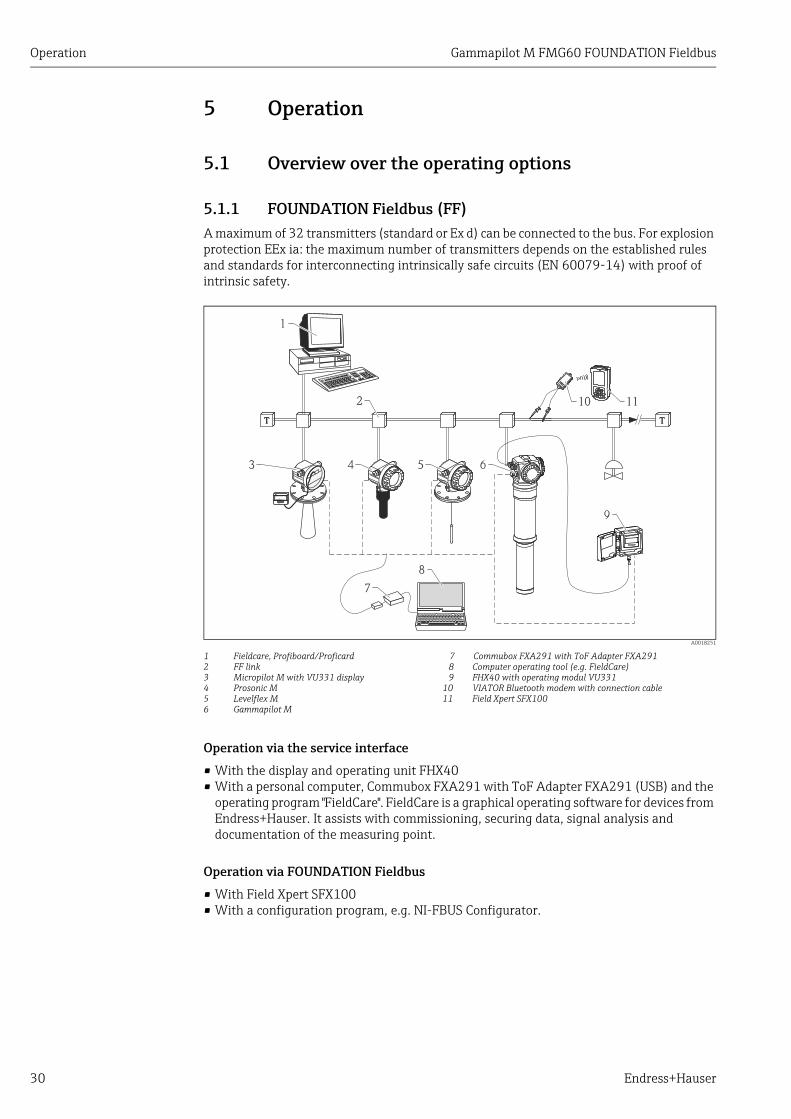
5.1.1 FOUNDATION Fieldbus (FF)A maximum of 32 transmitters (standard or Ex d) can be connected to the bus. For explosion protection EEx ia: the maximum number of transmitters depends on the established rules and standards for interconnecting intrinsically safe circuits (EN 60079-14) with proof of intrinsic safety.
A0018251
1 Fieldcare, Profiboard/Proficard 7 Commubox FXA291 with ToF Adapter FXA2912 FF link 8 Computer operating tool (e.g. FieldCare)3 Micropilot M with VU331 display 9 FHX40 with operating modul VU3314 Prosonic M 10 VIATOR Bluetooth modem with connection cable5 Levelflex M 11 Field Xpert SFX1006 Gammapilot M
Operation via the service interface
• With the display and operating unit FHX40• With a personal computer, Commubox FXA291 with ToF Adapter FXA291 (USB) and the
operating program "FieldCare". FieldCare is a graphical operating software for devices from Endress+Hauser. It assists with commissioning, securing data, signal analysis and documentation of the measuring point.
Operation via FOUNDATION Fieldbus
• With Field Xpert SFX100• With a configuration program, e.g. NI-FBUS Configurator.
ENDRESS + HAUSER
E+–
%
TT
1
2
3 4
7
8
9
5 6
10 11

Gammapilot M FMG60 FOUNDATION Fieldbus Operation
Endress+Hauser 31
5.2 Display operation
5.2.1 Display and operating elementsThe LCD module VU331 for displaying and operating is inside the remote display and operating unit FHX40. The measured value can be read off through the FHX40 sight glass. In order to operate the instrument, the FHX40 must be opened by removing the four screws.
A0018096
1 Gammapilot M2 FHX403 Operating module VU331
Display and operating module VU331
A0018097
1 Operating keys 4 Function name2 Bargraph 5 Parameter Identification number3 Symbols
Display symbols
The following table describes the symbols that appear on the liquid crystal display:
1
2
3
ENDRESS + HAUSER
E+–
1
2
3
4 5
Symbol Meaning
ALARM_SYMBOLThis alarm symbol appears when the instrument is in an alarm state. If the symbol flashes, this indicates a warning.
LOCK_SYMBOLThis lock symbol appears when the instrument is locked, i.e. if no input is possible.
COM_SYMBOLThis communication symbol appears when data transmission via HART, PROFIBUS PA or FOUNDATION Fieldbus, for example, is in progress.
SIMULATION_SWITCH_ENABLEThis communication symbol appears when simulation in FOUNDATION Fieldbus is enabled via the DIP switch.

Operation Gammapilot M FMG60 FOUNDATION Fieldbus
32 Endress+Hauser
Function of the keys
Key(s) Meaning
O or V Navigate upwards in the selection list.Edit numeric value within a function.
S or W Navigate downwards in the selection list.Edit numeric value within a function.
X or Z Navigate to the left within a function group.
F Navigate to the right within a function group, confirmation.
O and For
S and FContrast settings of the LCD.
O and S and FHardware lock / unlockAfter a hardware lock, an operation of the instrument via display or communication is not possible! The hardware can only be unlocked via the display. An unlock parameter must be entered to do so.

Gammapilot M FMG60 FOUNDATION Fieldbus Operation
Endress+Hauser 33
5.2.2 The operating menu
Function code
The functions of the Gammapilot M are arranged in an operating menu. To ensure easy orientation within the menu, a unique position code is indicated on the display for each function. This code consists of one alphabetic and two numeric characters.
A0019876-EN
1 Measuring mode2 Function group3 Function
• The alphabetic character specifies the current measuring mode of the Gammapilot M:– L: level– S: limit (switch)– D: density– C: concentration– *: no measuring mode selected yet
• The first numeric character identifies the function group:– basic setup *0– calibration *1– Safety settings *2– ...
• The second numeric character numbers the individual functions within the function group:basic setup *0– today's date *01– beam type *02– isotope *03– operating mode *04– ...
Hereafter, the position is always given in brackets after the function name. "*" (not yet selected) is always indicated as the measurement method, e.g. "present date" (*01).
1 2 3

Operation Gammapilot M FMG60 FOUNDATION Fieldbus
34 Endress+Hauser
Operation using the onsite display VU331
Selection and configuration in Operation menu:
1. Change from Measured Value Display to Group Selection by pressing F.
2. Press S or O to select the required Function Group and confirm by pressing F.The active selection is marked by a in front of the menu text.
3. Activate Edit mode with O or S.Selection menusa. Select the required parameter in the function selected with S or O.
b. F confirms selection; appears in front of the selected parameter.
c. F confirms the edited value; system quits edit mode.
d. Simultaneous pressing of O and S interrupts selection; system quits edit mode.
Typing in numerals and texta. Press O or S to edit the first character of the numeral / text.
b. F positions the cursor at the next character; continue with a. until you have completed your input.
c. If a symbol appears at the cursor, press F to accept the value entered; system quits edit mode.
d. If a symbol appears at the cursor, press F to return to the previous character (e.g. for correction of entries).
e. Simultaneous pressing of O and S interrupts selection; system quits edit mode.
4. Press F to select the next function.
5. Press O and S simultaneously once; return to previous function.Press O and S simultaneously twice; return to Group Selection.
6. Press O and S simultaneously to return to Measured value display.
Basic setup Todays date Isotop Return to group selection
Calibration 3 137 Cs
Safety setting 60Co
Temp. Comp. no comp.
Linearisation
...
>3 s
ESC E S C
S S
2xE S C
S
E S C
S
F
ENDRESS + HAUSER
E+–
S
F F
S

Gammapilot M FMG60 FOUNDATION Fieldbus Operation
Endress+Hauser 35
5.3 Alternative operation options
5.3.1 Operation via Field Xpert SFX100Compact, flexible and robust industry handheld terminal for remote parametrization and measured value inspection via the HART current output or FOUNDATION Fieldbus. For details refer to BA00060S/04/EN.
5.3.2 FieldCare operating programFieldCare is an Endress+Hauser asset management tool based on FDT technology. With FieldCare, you can configure all Endress+Hauser devices as well as devices from other manufacturers that support the FDT standard. Hardware and software requirements you can find on the internet:www.endress.com select your country search: FieldCare FieldCare Technical Data.
FieldCare supports the following functions:• Configuration of transmitters in online operation• Loading and saving device data (upload/download)• Documentation of the measuring point
Connection options:• Commubox FXA291 with ToF Adapter FXA291 via service interface
Operation Gammapilot M FMG60 FOUNDATION Fieldbus
36 Endress+Hauser
5.4 Lock/unlock configuration
5.4.1 Software security lockingEnter a number 2457 into the "unlock parameter" (*A4) function in the "diagnostics" (*A) function group.The symbol appears on the display. Changes are no longer possible.
If you try to change a parameter, the device jumps to the "unlock parameter" (*A4) function. Enter "2457". Parameters can be changed again.
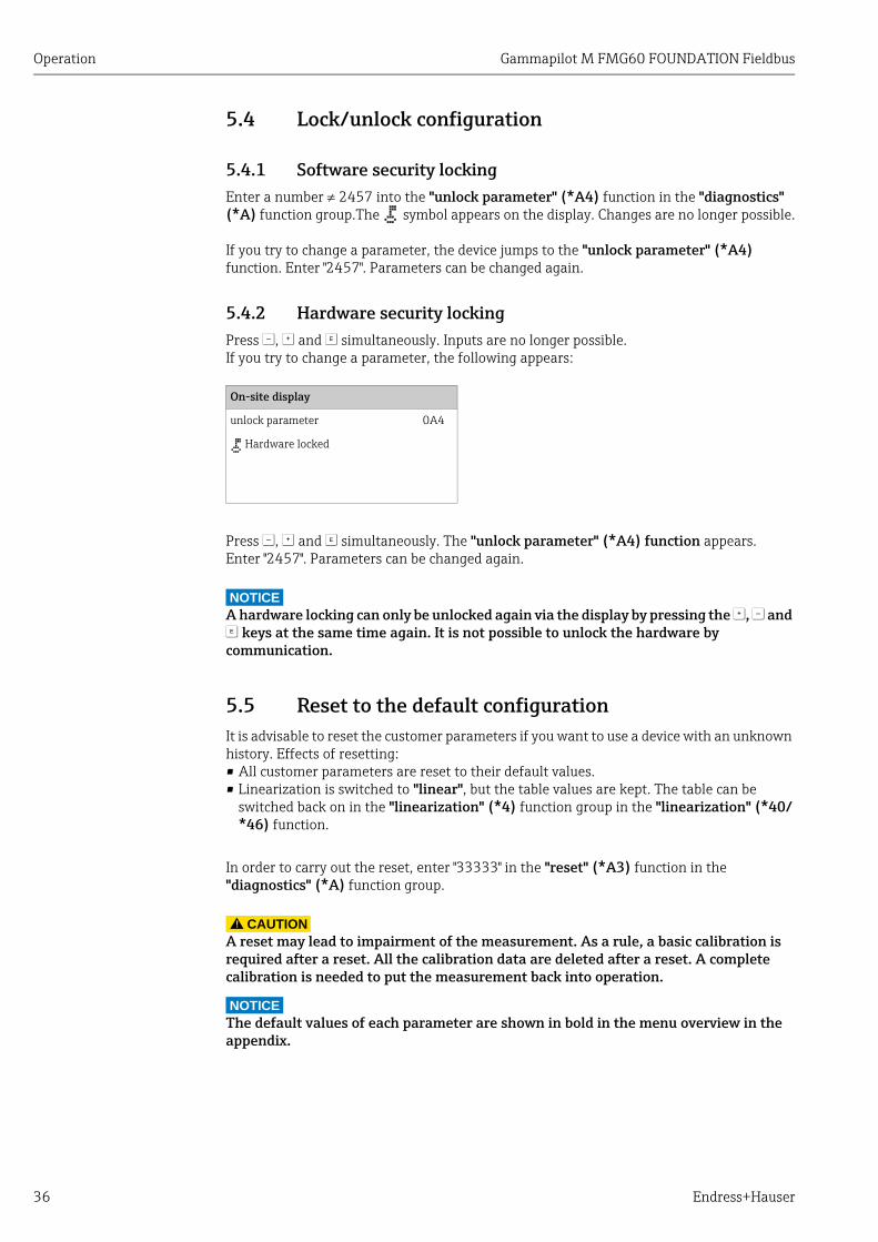
5.4.2 Hardware security lockingPress S, O and F simultaneously. Inputs are no longer possible.If you try to change a parameter, the following appears:
Press S, O and F simultaneously. The "unlock parameter" (*A4) function appears. Enter "2457". Parameters can be changed again.
NOTICEA hardware locking can only be unlocked again via the display by pressing the O, S and F keys at the same time again. It is not possible to unlock the hardware by communication.
5.5 Reset to the default configurationIt is advisable to reset the customer parameters if you want to use a device with an unknown history. Effects of resetting:• All customer parameters are reset to their default values.• Linearization is switched to "linear", but the table values are kept. The table can be
switched back on in the "linearization" (*4) function group in the "linearization" (*40/*46) function.
In order to carry out the reset, enter "33333" in the "reset" (*A3) function in the "diagnostics" (*A) function group.
CAUTION!
A reset may lead to impairment of the measurement. As a rule, a basic calibration is required after a reset. All the calibration data are deleted after a reset. A complete calibration is needed to put the measurement back into operation.
NOTICEThe default values of each parameter are shown in bold in the menu overview in the appendix.
On-site display
unlock parameter 0A4
Hardware locked

Gammapilot M FMG60 FOUNDATION Fieldbus Operation
Endress+Hauser 37
5.6 FOUNDATION Fieldbus interface
5.6.1 System architectureThe following diagram shows two typical examples of a FOUNDATION Fieldbus network with the associated components.
A0018251
1 Fieldcare, Profiboard/Proficard 7 Commubox FXA291 with ToF Adapter FXA2912 FF link 8 Computer operating tool (e.g. FieldCare)3 Micropilot M with VU331 display 9 FHX40 with operating modul VU3314 Prosonic M 10 VIATOR Bluetooth modem with connection cable5 Levelflex M 11 Field Xpert SFX1006 Gammapilot M
The system can be connected in the following ways:• A linking device makes the connection to higher-order fieldbus levels (e.g. High Speed
Ethernet (HSE)) possible.• A FOUNDATION Fieldbus-H1 connecting card is needed for direct connection to a process
control system.
NOTICEFurther information on FOUNDATION Fieldbus can be found in BA00013S/04/EN "FOUNDATION Fieldbus Overview, Installation and Commissioning Guidelines", the FOUNDATION Fieldbus Specification or on the Internet at "http://www. fieldbus.org".
ENDRESS + HAUSER
E+–
%
TT
1
2
3 4
7
8
9
5 6
10 11

Operation Gammapilot M FMG60 FOUNDATION Fieldbus
38 Endress+Hauser
5.6.2 Hardware settingsTwo DIP switches in connection compartment 2 allow the hardware setting for write protection and the simulation function. A diagram in the connection compartment explains the position of the switches (ON and OFF)
A0018671
Device identification
Foundation Fieldbus identifies the device by its identification code (device ID) and automatically allocates an appropriate field address. There is no separate hardware switch for this purpose.
Switch Position Meaning
SIM ON (down) Simulation possible in the configuration tool.
OFF (up) Simulation not possible in the configuration tool.
WP(write protection)
ON (down) Parameters can only be read.
OFF (up) Parameters can be written and read.
+ -
PT100PT100
IN CASCADE OUTIN CASCADE OUT
SIM WPSIM WP
OFFOFFON
3 4 5 6 7 8
9 10 11 12
+ - - ++ - - +
0
13
2
SIM WPSIM WP
OFFOFFON
9 10 11 12
Gammapilot M FMG60 FOUNDATION Fieldbus Operation
Endress+Hauser 39
5.6.3 Network configurationPrior to configuring the FF network, the device description (DD) of the Gammapilot M must be downloaded to the directory provided.
• Start the interface configuration tool.• Configure the interface.• Call the DD download routine.• Download the device descriptions (.ffo and .sym files) to the directory offered.• When the configuration is complete, close the tool and the FF stack (if open).
The Gammapilot M device descriptions can be ordered directly from Endress+Hauser or downloaded from our website "www.endress.com". They contain all data necessary to operate Endress+Hauser Foundation Fieldbus devices.
Example: Startup using the NI-Fieldbus configurator
Start the bus configuration tool. After startup, the tool shows the network configuration in the form of an expandable tree. If the Gammapilot M has been connected correctly, it is now recognized:
A double click on the name reveals the device data:
The device ID is made up of the following components:
whereby:
A right-hand mouse click on the name opens up a menu from which the PD_TAG and NODE_ADDRESS can be changed
E+H_GAMMAPILOT_M_XXXXXXXXXXX
PD_TAG The physical name of the device
DEVICE_ID The unique device identifier
NODE_ADDRESS Device address (is automatically allocated by the Configurator; can be changed subsequently by the user)
Device_ID = 452B481013-XXXXXXXXXXX
452B48 ID code for Endress+Hauser
1013 ID code for Gammapilot M
XXXXXXXXXXX Device serial number, as printed on the nameplate

Operation Gammapilot M FMG60 FOUNDATION Fieldbus
40 Endress+Hauser
A click on the name expands the device tree to show the function blocks available for it:
E+H_GAMMAPILOT_M_XXXXXXXXXXXRESOURCE_XXXXXX (RB2)TRANSDUCER_GAMMA_XXXXXX (TBG)DIAGNOSTIC_BLOCK_XXXXXX (DIAG)DISPLAY_BLOCK-XXXXXX (DISP)ANALOG_INPUT_1_XXXXXX (AI)ANALOG_INPUT_2_XXXXXX (AI)PID_XXXXXX(PID)AR_XXXXXX (AR)IS_XXXXXX (IS)SC_XXXXXX (SC)IT_XXXXXX (IT)

Gammapilot M FMG60 FOUNDATION Fieldbus Operation
Endress+Hauser 41
5.6.4 Block model of the Gammapilot MThe Gammapilot M contains the following blocks:• Resource block (RB2)
See Operating Instructions BA00013S/04/EN: "Foundation Fieldbus - Overview"• Transducer block (TB)
Contains the parameters relevant to measurement• Diagnostic block (DIAG)
Contains the diagnostic parameters of the Gammapilot M• Display block (DISP)
Contains the configuration parameters for the display module VU331• Analog Input block 1 or 2 (AI)
Scale the signals of the Transducer block and transmit them to the PLC• PID block (PID)
See Operating Instructions BA00013S/04/EN: "Foundation Fieldbus - Overview"• Arithmetic block (AR)
See Operating Instructions BA00013S/04/EN: "Foundation Fieldbus - Overview"• Input Selector block (IS)
See Operating Instructions BA00013S/04/EN: "Foundation Fieldbus - Overview"• Signal Characterizer block (SC)
See Operating Instructions BA00013S/04/EN: "Foundation Fieldbus - Overview"• Integrator block (IT)
See Operating Instructions BA00013S/04/EN: "Foundation Fieldbus - Overview"
Default block configuration
The input and output variables of the blocks can be interconnected by a network configuration tool (e.g. NI-Fieldbus configurator). The figure below shows, how these connections are set by default.
A0018673
Function block Describtion
Sensor Signal evaluation
Physical Block Parameters of the physical unit, e.g. tag No.
PID Block Automation functions
Transducer Block Parameters that describe the device (calibration, linearisation etc.)
Primary value Main value
Secondary value Pulse rate
Third value Temperature
Analog Input Function Block 1 Parameters that are important to the process control system, e.g. scaling, status
Analog Input Function Block 2 Parameters that are important to the process control system, e.g. scaling, status
OUT
OUT
Physical BlockDisplaySensor
Transducer
Block
Analog Input
Function Block 1
Analog Input
Function Block 1
PID Block
Primary value
Secondary value
Third value

Operation Gammapilot M FMG60 FOUNDATION Fieldbus
42 Endress+Hauser
5.6.5 Resource block
Operation
The Resource block contains the parameters used to describe physical resources of the device. It has no linkable inputs or outputs. The Resource block is opened by clicking the "resource" line.If the NI-FBUS Configurator is being used, a series of file tabs appears on the screen. The files can be opened to view and/or edit the parameters in the following table. A short description of the parameter function appears on the side of the screen. A change in the parameter is stored by pressing the WRITE CHANGES button when the block is out of service. Press the READ ALL button to check the values stored in the device.
Parameter
The functions of the Resource block not described here can be found in the Foundation Fieldbus specification, see "www.fieldbus.org".
E+H_GAMMAPILOT_M_XXXXXXXXXXXRESOURCE_XXXXXX (RB2)TRANSDUCER_XXXXXX (TBUL)ANALOG_INPUT_1_XXXXXX (AI)
Parameter Description
TAG_DESC User description of the intended application of the block.
MODE_BLK Lists the actual, target, permitted and normal operating modes of the block.– Target: changes the operating mode of the block– Actual: indicates the current operating mode of the block– Permitted: states which operating modes are allowed– Normal: indicates the normal operating mode of the block
The possible operating modes of the resources block are:– AUTO: the block is operating as normal– OOS: the block is out of service.
If the Resource block is out of service, then all blocks within the device (resource) are forced into the same status.
RS_STATE Indicates the state of the Resource block application state machine– On-line: block in AUTO mode– Standby: block in OOS mode
WRITE_LOCK Indicates the status of DIP-switch WP– LOCKED: device data can be modified– NOT LOCKED: device data can be modified
RESTART Allows a manual restart:– UNINITIALISED: no status– RUN: normal operational status– RESOURCE: resets the Resource block parameters– DEFAULTS: resets all Foundation Fieldbus parameters within the device,
but not the manufacturer-specific parameters.– PROCESSOR: make a warm start of the processor
BLOCK_ERROR Shows error status of software and hardware components– Out-of-Service: the block is in OOS mode– Simulation active: shows the setting of DIP-switch SIM
BLOCK_ALM Shows any configuration, hardware, connection and system problems in the lock. The cause of the alert is to be seen in the subcode field.

Gammapilot M FMG60 FOUNDATION Fieldbus Operation
Endress+Hauser 43
5.6.6 Transducer block
Operation
The Transducer block contains the parameters required to calibrate the device. These parameters can also be read out and edited using the VU331 display module. The calibration of the device is described in ä 54, "Commissioning". The Transducer block is opened by clicking the "transducer" line. Parameter changes from the tool are made off-line while the device is operating. The changes are downloaded by first setting MODE_BLK = OOS then pressing the WRITE CHANGES button. If you want to check all the values saved in the device, click READ ALL. To return to operation, set the MODE_BLK to AUTO6).
Block administration parameters
Output values
Configuration parameters
The Transducer block also contains the configuration parameters which are used to commission and calibrate the device. They are identical to the functions of the operating menu, except for the service parameters which are not accessible on the bus. Thus, the calibration procedure via the display module ( ä 54, "Commissioning") is equally valid for a calibration via a network configuration tool. A complete description of all the configuration parameters can be found in Operating Instructions BA00287F/00/EN, "Gammapilot M FMG60 - Description of Device Functions".
E+H_GAMMAPILOT_M_XXXXXXXXRESOURCE_XXXXXX (RB2)TRANSDUCER_XXXXXX (TBUL)ANALOG_INPUT_1_XXXXXX (AI)
6) If MODE_BLK refuses to be changed to AUTO, an error is present. Control all parameters, perform the required changes and try again to change MODE_BLK to AUTO.
Parameter Description
MODE_BLK See description in Resource block. The possible operating modes of the Transducer block are:– AUTO: the block is operating as normal– OOS: the block is out of service.
TAG_DESC User description of the intended application of the block.
BLOCK_ERROR Shows the error status in conjunction with the block components.– Out-of-service: the block is in OOS mode
Parameter Description
PRIMARY_VALUE Main value (level, level limit, density or concentration).
SECONDARY_VALUE Pulse rate
THIRD_VALUE Medium temperature

Operation Gammapilot M FMG60 FOUNDATION Fieldbus
44 Endress+Hauser
Parameter list of the Gammapilot M Transducer block
Parameter Position Indicator
rel.Index
Variable Name Size[bytes]
Type Read Write Storage Class
0 EH_USONICLEVEL_CAL_BASIC
Standard parameters
ST_REV 1 ST_REV 2 UNSIGNED16 X static
TAG_DESC 2 TAG_DESC 32 OCTET_STRING X X static
STRATEGY 3 STRATEGY 2 UNSIGNED16 X X static
ALERT_KEY 4 ALERT_KEY 1 UNSIGNED8 X X static
MODE_BLK 5 MODE_BLK 4 DS-69 X X static
BLOCK_ERROR 6 BLOCK_ERROR 2 BIT_STRING X dynamic
UPDATE_EVT 7 UPDATE_EVT 14 DS-73 X dynamic
BLOCK_ALM 8 BLOCK_ALM 13 DS-72 X X dynamic
Transducer Directory Entry 9 TRANSDUCER_DIRECTORY 2 UNSIGNED16 X non-vol.
Transducer Type 10 TRANSDUCER_TYPE 2 UNSIGNED16 X non-vol.
Transducer Error 11 XD_ERROR 1 UNSIGNED8 X static
Collection Directory 12 COLLECTION_DIRECTORY 4 UNSIGNED32 X non-vol.
Primary Value Type 13 PRIMARY_VALUE_TYPE 2 UNSIGNED16 X X static
Primary Value 14 PRIMARY_VALUE 5 DS-65 X dynamic
Primary Value Range 15 PRIMARY_VALUE_RANGE 11 DS-68 X non-vol.
Secondary Value 16 SECONDARY_VALUE 5 DS-65 X dynamic
Secondary Value Unit 17 SECONDARY_VALUE_UNIT 2 UNSIGNED16 X X static
Third Value 18 THIRD_VALUE 5 DS-65 X dynamic
Third Value Unit 19 THIRD_VALUE_UNIT 2 UNSIGNED16 X X static
Instrument specific parameters
measured value *00 20 SENSOROUTVALUE 4 FLOAT X dynamic
Present date day *01 21 PRESENTDATEDAY 1 UNSIGNED8 X X dynamic
Present date month *01 22 PRESENTDATEMONTH 1 UNSIGNED8 X X dynamic
Present date year *01 23 PRESENTDATEYEAR 1 UNSIGNED8 X X dynamic
Present date hour *01 24 PRESENTDATEHOUR 1 UNSIGNED8 X X dynamic
Present date minute *01 25 PRESENTDATEMINUTE 1 UNSIGNED8 X X dynamic
Ray type *02 26 RAYTYPE 1 ENUM8 X X non-vol.
Radiation source *03 27 RADIATIONSOURCE 1 ENUM8 X X non-vol.
Master slave mode *04 28 MASTERSLAVEMODE 1 ENUM8 X X non-vol.
Measurement method *05 29 MEASUREMENTMODE 1 ENUM8 X X non-vol.
Density unit *06 30 DENSITYUNIT16 2 ENUM16 X X non-vol.
Min. density *07 31 DENSITY4MAVALUE 4 FLOAT X X non-vol.
Max. density *08 32 DENSITY20MAVALUE 4 FLOAT X X non-vol.
Pipe diameter unit *09 33 PIPEDIAMUNIT16 2 ENUM16 X X non-vol.
Pipe diameter *0A 34 PIPEDIAMETER 4 FLOAT X X non-vol.
Output damping *0B 35 INTEGRATIONTIME 2 UNSIGNED16 X X non-vol.
Background calibration *10 36 BACKGRCALIB 1 ENUM8 X X non-vol.
Avg. pulse rate *11 37 AVGPULSERATE 4 INTEGER32 X dynamic
Background pulse rate *12 38 BACKGRPULSERATE 4 INTEGER32 X X non-vol.

Gammapilot M FMG60 FOUNDATION Fieldbus Operation
Endress+Hauser 45
Calibr. point level *13 39 CALIBRATIONPOINTLEVEL 1 ENUM8 X non-vol.
Value full *14 40 TARGETVALUEFULL 4 FLOAT X X non-vol.
Calibration start stop *15 41 CALIBRATIONSTARTSTOP 1 ENUM8 X X non-vol.
Full calib. pulse rate *16 42 CALIBRPULSERATEFULL 4 INTEGER32 X X non-vol.
Value empty *17 43 TARGETVALUEMPTY 4 FLOAT X X non-vol.
Empty calibr. pulse rate *18 44 CALIBRPULSERATEEMPTY 4 INTEGER32 X X non-vol.
Calibr. point density *1A 45 CALIBRATIONPOINTDENSITY 1 UNSIGNED8 X X non-vol.
Density calibr. *1B 46 DENSITYCALIBR 4 INTEGER32 X X non-vol.
Density value *1C 47 DENSITYVALUE 4 FLOAT X X non-vol.
Use of cal point *1D 48 USEOFCALPOINT 1 ENUM8 X X non-vol.
Absorption coefficient *1E 49 ABSORPCOEFF 4 FLOAT X X non-vol.
Ref. pulse rate *1F 50 REFPULSERATE 4 UNSIGNED32 X dynamic
Output on alarm *20 51 OUTPUTONALARM 1 ENUM8 X X non-vol.
Temperature compensation *30 52 TEMPCOMPENSATION 1 ENUM8 X X non-vol.
Select temperature *31 53 SELECTTEMPERATURE 1 ENUM8 X non-vol.
Temp. value *32 54 TEMPVALUE 4 FLOAT X X non-vol.
density *33 55 TEMPDENSITYVALUE 4 FLOAT X X non-vol.
Linear coefficient *34 56 LINTEMPCOEFF 4 FLOAT X non-vol.
Square coefficient *35 57 SQUARETEMPCOEFF 4 FLOAT X non-vol.
Linearization (level) *40 58 GAMMALINEARISATIONLEVEL 1 ENUM8 X X non-vol.
Lin. table number *41 59 SENSLINTABLENUMBER 1 UNSIGNED8 X X non-vol.
Input level *42 60 INPUTOUTLEVEL 4 FLOAT X X non-vol.
Linearization start stop *43 61 LINEARISATIONSTARTSTOP 1 ENUM8 X X non-vol.
Normal. pulse rate *44 62 CALIBRPULSERATELIN 4 INTEGER32 X X non-vol.
Unit selection *45 63 UNITSELECTION 1 ENUM8 X X non-vol.
Customer unit *46 64 CUSTUNITCONCENTR16 1 ENUM16 X X non-vol.
Linearization concentr. *47 65 LINEARISATIONCONCENTR 1 ENUM8 X X non-vol.
Table no. concentr. *48 66 TABLENUMBERCONCENTR 1 UNSIGNED8 X X non-vol.
Input density *49 67 INPUTDENSITY 4 FLOAT X X non-vol.
Input concentration *4A 68 INPUTCONCENTR 4 FLOAT X X non-vol.
Gammagraphy detection *50 69 GAMMAGRAPHYDETECTION 1 ENUM8 X X non-vol.
Span time *51 70 SPANTIME 2 UNSIGNED16 X X non-vol.
Gammagr. sensitivity *52 71 GAMMAGRSENSITIVITY 1 UNSIGNED8 X X non-vol.
Output at gammagraphy *53 72 GAMMAGROUTPUT 1 ENUM8 X X non-vol.
Gammagr. hold time *54 73 GAMMAGRHOLDTIME 2 UNSIGNED16 X X non-vol.
Gammagr. counter *55 74 GAMMAGRCOUNTER 2 UNSIGNED16 X non-vol.
Gammagr. counter reset *56 75 GAMMAGRCOUNTERRESET 1 ENUM8 X X non-vol.
Simulation (level) L65 76 SIMLEVELMODE 1 ENUM8 X X non-vol.
Simulation (density) D65 77 SIMDENSITYMODE 1 ENUM8 X X non-vol.
Simulation (concentration) C65 78 SIMCONCTRMODE 1 ENUM8 X X non-vol.
Simulation value (level) L66 79 SIMULATIONVALUELEVEL 4 FLOAT X X non-vol.
Simulation value (pulse rate)
*66 80 SIMULATIONVALUEPULSR 4 INTEGER32 X X non-vol.
Parameter Position Indicator
rel.Index
Variable Name Size[bytes]
Type Read Write Storage Class

Operation Gammapilot M FMG60 FOUNDATION Fieldbus
46 Endress+Hauser
Simulation value (density) D66 81 SIMULATIONVALUEDENSITY 4 FLOAT X X non-vol.
Simulation value (concentr.) C66 82 SIMULATIONVALUECONCTR 4 FLOAT X X non-vol.
Unlock parameter *A4 83 OPERATIONCODEFFPA 2 UNSIGNED16 X X non-vol.
Pres. avg. pulse rate *A5 84 PRESAVGPULSERATE 4 INTEGER32 X X dynamic
Avg. raw pulse rate *A6 85 AVGRAWPULSERATE 4 INTEGER32 X X dynamic
Medium temperature *A7 86 MEDIUMTEMP 4 FLOAT X X dynamic
Density value *A8 87 DENSITYNOTTEMPCOMP 4 FLOAT X X dynamic
Temp. unit *C6 88 TEMPERATUREUNIT16 2 ENUM16 X X non-vol.
Calibration date day *C7 89 CALIBRATIONDATEDAY 1 UNSIGNED8 X X non-vol.
Calibration date month *C7 90 CALIBRATIONSDATEMONTH 1 UNSIGNED8 X X non-vol.
Calibration date year *C7 91 CALIBRATIONDATEYEAR 1 UNSIGNED8 X X non-vol.
Calibration date hour *C7 92 CALIBRATIONDATEHOUR 1 UNSIGNED8 X X non-vol.
Calibration date minute *C7 93 CALIBRATIONDATEMINUTE 1 UNSIGNED8 X X non-vol.
Recalibration date day *C8 94 RECALIBRATIONDATEDAY 1 UNSIGNED8 X X non-vol.
Recalibration date month *C8 95 RECALIBRATIONDATEMONTH 1 UNSIGNED8 X X non-vol.
Recalibration date year *C8 96 RECALIBRATIONDATEYEAR 1 UNSIGNED8 X X non-vol.
Recalibration date hour *C8 97 RECALIBRATIONDATEHOUR 1 UNSIGNED8 X X non-vol.
Recalibration date minute *C8 98 RECALIBRATIONDATEMINUTE 1 UNSIGNED8 X X non-vol.
Parameter Position Indicator
rel.Index
Variable Name Size[bytes]
Type Read Write Storage Class

Gammapilot M FMG60 FOUNDATION Fieldbus Operation
Endress+Hauser 47
5.6.7 Diagnostic block
Operation
The Diagnostic block contains the error messages of the device. These parameters can also be read out and edited using the VU331 display module. The Diagnostic block is opened by clicking the "diagnostic" line. Parameter changes from the tool are made off-line while the device is operating. The changes are downloaded by first setting MODE_BLK = OOS then pressing the WRITE CHANGES button. If you want to check all the values saved in the device, click READ ALL. To return to operation, set the MODE_BLK to AUTO7).
Block administration parameters
Instrument specific parameters
E+H_GAMMAPILOT_M_XXXXXXXXTRANSDUCER_XXXXXX (TB)DIAGNOSTIC_XXXXXX (DIAG)DISPLAY_XXXXXX (DISP)
7) If MODE_BLK refuses to be changed to AUTO, an error is present. Control all parameters, perform the required changes and try again to change MODE_BLK to AUTO.
Parameter Description
MODE_BLK See description in Resource block. The possible operating modes of the Transducer block are:– AUTO: the block is operating as normal– OOS: the block is out of service.
TAG_DESC User description of the intended application of the block.
BLOCK_ERROR Shows the error status in conjunction with the block components.– Out-of-service: the block is in OOS mode
Parameter Position Indicator
rel.Index
Variable Name Size[bytes]
Type Read Write Storage Class
present error *A0 13 ACTUALERROR 2 UNSIGNED16 X dynamic
previous error *A1 14 LASTERROR 2 UNSIGNED16 X non-vol.
Clear last error *A2 15 CLEARLASTERROR 1 ENUM8 X X dynamic
Reset *A3 16 RESET 2 UNSIGNED16 X X dynamic
Unlock parameter *A4 17 OPERATIONCODE 2 UNSIGNED16 X X non-vol.
protocol+sw-no. *C2 18 PROSOFTVERSIONSTRING 16 VISIBLE STRING X constant

Operation Gammapilot M FMG60 FOUNDATION Fieldbus
48 Endress+Hauser
5.6.8 Display block
Operation
The Display block contains the parameters required to configure the display module VU331 (which is contained in the remote display and operating unit FHX40). These parameters can also be read out and edited using the VU331 display module. The Display block is opened by clicking the "display" line. Parameter changes from the tool are made off-line while the device is operating. The changes are downloaded by first setting MODE_BLK = OOS then pressing the WRITE CHANGES button. If you want to check all the values saved in the device, click READ ALL. To return to operation, set the MODE_BLK to AUTO 8).
Block administration parameters
Instrument specific parameters
E+H_GAMMAPILOT_M_XXXXXXXXDIAGNOSTIC_XXXXXX (DIAG)DISPLAY_XXXXXX (DISP)ANALOG_INPUT_XXXXXX (AI)
8) If MODE_BLK refuses to be changed to AUTO, an error is present. Control all parameters, perform the required changes and try again to change MODE_BLK to AUTO.
Parameter Description
MODE_BLK See description in Resource block. The possible operating modes of the Transducer block are:– AUTO: the block is operating as normal– OOS: the block is out of service.
TAG_DESC User description of the intended application of the block.
BLOCK_ERROR Shows the error status in conjunction with the block components.– Out-of-service: the block is in OOS mode
Parameter Position Indicator
rel.Index
Variable Name Size[bytes]
Type Read Write Storage Class
language *92 13 LANGUAGE 1 ENUM8 X X non-vol.
Back to home *93 14 BACKTOHOME 1 INT16 X X non-vol.
No. of decimals *95 15 NOOFDECIMALS 1 ENUM8 X X non-vol.
sep. character *96 16 SEPARATIONCHARACTER 1 ENUM8 X X non-vol.
Unlock parameter *A4 17 OPERATIONCODE 2 UNSIGNED16 X X non-vol.

Gammapilot M FMG60 FOUNDATION Fieldbus Operation
Endress+Hauser 49
5.6.9 Analog Input block
The Analog Input block processes the signal output by the Transducer block and forwards it to the PLC or other function blocks.
A0018675
Operation
The Analog Input block is opened by clicking the "Analog_Input" line.Parameter changes from the tool are made off-line while the device is operating. The changes are downloaded by first setting MODE_BLK = OOS then pressing the WRITE CHANGES button. If you want to check all the values saved in the device, click READ ALL. Operation normally resumes as soon as MODE_BLK is set to AUTO.
Block administration parameters
E+H_Gammapilot_M_XXXXXXXXRESOURCE_XXXXXX (RB2)TRANSDUCER_XXXXXX (TBUL)ANALOG_INPUT_1_XXXXXX (AI)
Parameter Description
MODE_BLK See description in Resource block. The possible operating modes of the Transducer block are:– AUTO: the block is operating as normal– MAN: the block is operated with a manually entered primary value.– OOS: the block is out of service.
TAG_DESC User description of the intended application of the block.
BLOCK_ERROR Shows the error status in conjunction with the block components.– Out-of-service: the block is in OOS mode– Simulation active: shows the setting of DIP-switch SIM. Input error/process
variable with BAD status.– configuration error
L_T
YP
E
XD
_SC
ALE
SIM
ULA
TE
CH
AN
NE
L
DIRECT
INDIRECT
INDIRECT
SQRT
OU
T_SC
ALE
ALA
RM
S
OUT
HI_HI
HI
LO
LO_LO
0
EU
0 0
1
1 1
0
1
0 1
FIELD_VAL
EU
EU
EU
�
PV
_T
IME
MO
DE
STA
TU
S
0 10
1
PROCESS VALUE (PV)
Tra
nsd
uce
r B
lock
PR
IMA
RY
/ S
EC
ON
DA
RY
VA
LU
E

Operation Gammapilot M FMG60 FOUNDATION Fieldbus
50 Endress+Hauser
Output values
Scaling parameters
The relationship between the output values and scaling parameters is as follows:
The L_TYPE parameter influences the signal conversion:• Direct:
• Indirect:
• Indirect square root:
Parameter Description
PV Either the primary/secondary output value of the Transducer block or a value associated with it. Comprises value and status.
OUT The primary value output as a result of executing the Analog Input block. Comprises value and status.
FIELD_VALUE Raw value of field device in % of PV range with a status reflecting the Sensor condition before signal characterization L_Type or filtering V_TIME. Comprises value and status.
Parameter Description
CHANNEL Selects the measured value to be input to the Analog Input block– 0 = no channel defined– 1 = primary value: measured level/volume– 2 = secondary value: measured distance
XD_SCALE Scales the Transducer block value to the required engineering unit (EU).
OUT_SCALE Scales the output value in the required engineering units (EU).
L_TYPE Sets the linearization type:– DIRECT: the Transducer block bypasses the scaling functions– INDIRECT: the Transducer block value is fed through the linear scaling
functions– INDIRECT SQRT: the Transducer block value is fed through the square root
scaling functions
FIELD_VAL = 100 x
CHANNEL_VALUE - XD_SCALE_MIN
XD_SCALE_MAX - XD_SCALE_MIN
PV = CHANNEL_VALUE
PV = FIELD_VALUE
x (OUT_SCALE_MAX - OUT_SCALE_MIN) + OUT_SCALE_MIN100
PV = (FIELD_VALUE/100)1/2 x OUT_SCALE_MAX - OUT_SCALE_MIN) + OUT_SCALE_MIN

Gammapilot M FMG60 FOUNDATION Fieldbus Operation
Endress+Hauser 51
Output response parameters
Alarm parameters
Alarm priorities
Alarm status
Parameter Description
LOW_CUT Not relevant to level measurement!Determines a threshold for square root linearization below which the output value is set to zero.
PV_FTIME Sets the time constant for the output value.
Parameter Description
ACK_OPTION Sets the way in which alarms and warnings are to be acknowledged.
ALARM_HYS Sets the hysteresis (in output engineering units) for all configured alarms.A hysteresis of e.g. 2% on a HI_HI_LIMIT of 95% would cause the alarm to activate when the level reaches 95% and to deactivate when the level drops below 93%.A hysteresis of e.g. 2% on a LO_LO_LIMIT of 5% would cause the alarm to activate when the level drops below 5% and to deactivate when the level rises to 7%.
HI_HI_PRI The priority (1 – 15) of the HI_HI alarm
HI_HI_LIM Sets the HI_HI alarm limit in output engineering units
HI_PRI The priority (1 – 15) of the HI alarm
HI_LIM Sets the HI warning limit in output engineering units
LO_PRI The priority (1 – 15) of the LO alarm
LO_LIM Sets the LO warning limit in output engineering units
LO_LO_PRI The priority (1 – 15) of the LO_LO alarm
LO_LO_LIM Sets the LO_LO alarm limit in output engineering units
Parameter Description
0 Alarm is suppressed
1 Recognized by the system but not reported
2 Reported to the operator, but does not require his attention
3 - 7 Advisory alarms of increasing priority
8 - 15 Critical alarms of increasing priority
Parameter Description
HI_HI_ALM The status of the HI_HI alarm
HI_ALM The status of the HI alarm
LO_ALM The status of the LO alarm
LO_LO_ALM The status of the LO_LO alarm

Operation Gammapilot M FMG60 FOUNDATION Fieldbus
52 Endress+Hauser
Simulation
The SIMULATE parameter allows the Transducer block output value to be simulated, provided simulation has also been enabled at the device DIP switch. The simulation must be enabled, a value and/or status entered and the block must be in AUTO mode. During simulation the Transducer block output value is substituted by the simulated value.A simulation is also possible by switching MODE_BLK to "MAN" and entering a value for OUT.
5.6.10 Checklist for commissioningThe following checklist refers to the configuration via the NI-Fieldbus configurator. In general, the operation is rather similar for other network design tools.
1. Configure the network and integrate the device.– Identify the device by means of the device ID and serial number.– If appropriate, assign a new PD_TAG.
2. Configure the Resource block.– Check the position of the hardware switch in WRITE_LOCK– If "locked" is displayed, change the position of the DIP-switch.– If appropriate, change the block tag (right-hand click on tree).– Set MODE_BLK_TARGET to Out-of-Service.– Reset the device to factory values by using the function RESTART Þ Defaults
(this function may also be available with a right-hand click on the device name)– If appropriate, assign a new tag description (TAG_DESC).– Set MODE_BLK_TARGET to Auto.
3. Configure the Transducer block, Diagnostic block and Display block. – If appropriate, change the block tag (right-hand click on tree).– Set MODE_BLK_TARGET to Out-of-Service.– If appropriate, assign a new tag description (TAG_DESC).– Configure the device as described in the "basic setup" section.– Set MODE_BLK_TARGET to Auto.
4. Configure the Analog Input block.– If appropriate, change the block tag (right-hand click on tree).– Set MODE_BLK_TARGET to Out-of-Service.– If appropriate, assign a new tag description (TAG_DESC).– Set Channel to measured value or distance.– Set L_TYPE to "DIRECT" if the OUT value is to be in technical units e.g. ft to "INDIRECT"
if the OUT value is to be scaled.– Set the desired output damping in PV_TIME.– If appropriate, set the advisory and critical alarms.– Set MODE_BLK_TARGET to Auto.
5. Link the function blocks in the function block editor.
6. Download the configuration (menu configure).
7. If appropriate, check the configuration by using the SIMULATE function.
Parameter Description
SIMULATE Enables, sets and displays a simulated value, options:– enable/disable– simulated value– output value
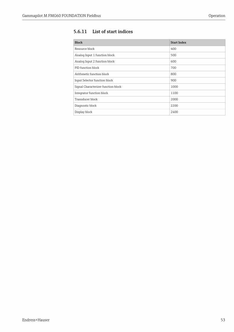
Gammapilot M FMG60 FOUNDATION Fieldbus Operation
Endress+Hauser 53
5.6.11 List of start indices
Block Start Index
Resource block 400
Analog Input 1 function block 500
Analog Input 2 function block 600
PID function block 700
Arithmetic function block 800
Input Selector function block 900
Signal Characterizer function block 1000
Integrator function block 1100
Transducer block 2000
Diagnostic block 2200
Display block 2400

Commissioning Gammapilot M FMG60 FOUNDATION Fieldbus
54 Endress+Hauser
6 CommissioningNOTICE
This chapter describes the commissioning of the Gammapilot M using the operating module VU331 (which is located in the remote display and operating unit FHX40). Commissioning using the "FieldCare" or the "Field Xpert SFX100" is similar. For further instructions to the operating program "FieldCare" see BA00027S/04/EN or the BA00060S/04/EN supplied together with the Field Xpert SFX100.
6.1 Calibration: overview
A detailed description of the functions used can be found in the following sections: ä 60, "Basic setup" ä 66, "Calibration for level measurement and limit detection" ä 75, "Calibration for density and concentration measurements" ä 83, "Density measurement/temperature-compensated"
Power up instrument
see ä 59, "Switching on the device"
Basic setup
see ä 60, "Basic setup"
Calibration for level measure-ment and level limit detection
Calibration for density and con-centration measurements
Calibration for density measure-ments/ temperature compensa-ted
see ä 66, "Calibration for level measurement and limit detection"
see ä 75, "Calibration for den-sity and concentration measure-ments"
see ä 83, "Density measure-ment/temperature-compensated"
Additional settings
see "Description of Instrument Func-tions"BA00287F/00/EN

Gammapilot M FMG60 FOUNDATION Fieldbus Commissioning
Endress+Hauser 55
6.1.1 Basic setup
Step Function Entry or selection Comments See page
1 Present date (*01) e.g. 12.11.04 10:30
Set day with O and S ;Confirm with F;The same applies for month, year, hour and minute
ä 60
2 Beam type (*02) • standard/cont.• modulated
Select with O and S;Confirm with F
ä 60
3 Isotope (*03) • 137Cs• 60Co• no compensation
Select with O and S;Confirm with F
ä 60
4 Operating mode (*04) • Stand alone• Master• Slave• End-slave• not defined
Select with O and S;Confirm with F
ä 61
5 Measurement mode (*05)
• level• limit• density• concentration
Select with O and S;Confirm with F
ä 62
The following functions for density and concentration measurements only:
6 Density unit (*06) • g/cm3
• g/l• ...
Select with O and S;Confirm with F
ä 63
7 Min. density (*07)(lower limit of the measuring range)
e.g. 0.9500 g/cm3
Set each decimal place with O and S and confirm with F;After the last place: confirm the whole value with F.
ä 63
8 Max. density (*08)(upper limit of the measuring range)
e.g. 1.2500 g/cm3
Set each decimal place with O and S and confirm with F;After the last place: confirm the whole value with F.
ä 63
9 Pipe diameter unit (*09) • mm• inch
Select with O and S;Confirm with F
ä 63
10 Pipe diameter (*0A) e.g. 200 mm
Set each decimal place with O and S and confirm with F;After the last place: confirm the whole value with F.
ä 64
The following function for all measurement methods:
11 Output damping (*0B) e.g. 60 s Set each decimal place with O and S and confirm with F;After the last place: confirm the whole value with F.
ä 65

Commissioning Gammapilot M FMG60 FOUNDATION Fieldbus
56 Endress+Hauser
6.1.2 Calibration for level measurement and limit detection
NOTICEThe fundamentals for calibrating for level measurement and level limit detection are described in "Calibration for level measurement and limit detection", ä 66.
Background calibration
For details see "Background calibration", ä 69.
"Full" or "covered" calibration
For details see "Full and empty calibration or covered and free calibration", ä 71.
Step Function Action/comments
1 • Switch off radiation• Fill tank
for level: min. 60%for level limit: beam path covered
2 Background calibration (*10) Select "start" with O or S;confirm with F
3 Avg. pulse rate (*11) Wait until the value is stable, then confirm with F
4 Background calibration (*10) Select "stop/edit" with O or S;confirm with F
5 Background pulse rate (*12) Confirm value with F
Continue with full and empty calibration/covered and free calibration
Step Function Action/comments
1 • Switch on radiation• Tank remains filled.
2 Calibration point level (*13) Select "full/covered" with O or S;confirm with F
The following function for level measurement only
3 Value full (*14) Enter the current level (60% - 100%)
The following functions for level and level limit measurement
4 Calibration start stop (*15) Select "start" with O or S;confirm with F
5 Avg. pulse rate (*11) Wait until the value is stable, then confirm with F
6 Calibration start stop (*15) Select "stop/edit" with O or S;confirm with F
7 Full calibration pulse rate (*16) Confirm value with F
8 Calibration next point (*19) Select "yes" with O or S;Confirm with F
Continue with "empty" or "free" calibration

Gammapilot M FMG60 FOUNDATION Fieldbus Commissioning
Endress+Hauser 57
"Empty" or "free" calibration
For details see "Full and empty calibration or covered and free calibration", ä 71.
Step Function Action/comments
1 • The radiation remains switched on• Empty tank
Level: max. 40%Level limit: beam path free
2 Calibration point level (*13) Select "empty/free" with O or S;confirm with F
The following function for level measurement only
3 Value empty (*17) Enter the current level (0% - 40%)
The following functions for level and level limit measurement
4 Calibration start stop (*15) Select "start" with O or S;confirm with F
5 Avg. pulse rate (*11) Wait until the value is stable, then confirm with F
6 Calibration start stop (*15) Select "stop/edit" with O or S;confirm with F
7 Empty calibration (*16) Confirm value with F
8 Calibration next point (*19) Select "no" with O or S;Confirm with F
This completes the calibration.

Commissioning Gammapilot M FMG60 FOUNDATION Fieldbus
58 Endress+Hauser
6.1.3 Calibration for density and concentration measurements
NOTICEThe fundamentals for calibrating for density and concentration measurement are described in "Basic principles", ä 75.
Background calibration
For details see "Background calibration", ä 77.
Calibration points (one-point calibration, multiple point calibration, recalibration)
For details see "Calibration points", ä 79.
Step Function Action/comments
1 Switch off radiation
2 Background calibration (*10) Select "start" with O or S;confirm with F
3 Avg. pulse rate (*11) Wait until the value is stable, then confirm with F
4 Background calibration (*10) Select "stop/edit" with O or S;confirm with F
5 Background pulse rate (*12) Confirm value with F
Continue with entering the calibration points
Step Function Action/comments
1 • Switch on radiation• Fill the pipe with a medium whose density is known or take a
sample of the medium during the calibration and determine its density in the laboratory (see Step 4).
2 Calibration point density (*1A) Enter the number of the calibration point:• For one-point calibration: "1"• For multipoint calibration: "1" - "9"• For recalibration: "10"
3 Calibration start stop (*15) Select "start" with O or S;confirm with F
4 Avg. pulse rate (*11) Wait until the value is stable, then confirm with F;(during this time, take a sample of the medium and determine its density in the laboratory)
5 Calibration start stop (*15) Select "stop/edit" with O or S;confirm with F
6 Density calibration (*1B) Confirm value with F
7 Density value (*1C) Enter the density of the medium (which was determined in the laboratory)
8 Use of cal. point (*1D) Select "used" with O or S;confirm with F
9 Absorption coefficient (*1E) Display value; confirm with F
10 Reference pulse rate (*1F) Display value; confirm with F
11 Calibration next point (*19) • For one-point calibration: select "no";this completes the calibration
• For multiple point calibration: select "yes";repeats steps 1 - 10 with a medium with a different density
• For recalibration: select "no";this completes the recalibration
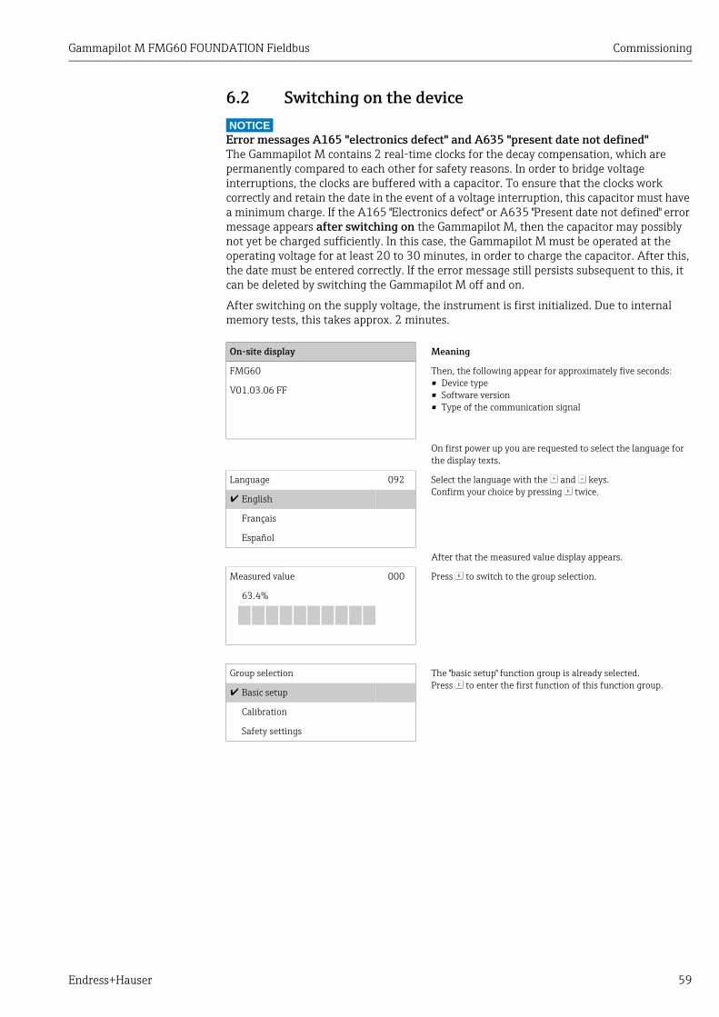
Gammapilot M FMG60 FOUNDATION Fieldbus Commissioning
Endress+Hauser 59
6.2 Switching on the deviceNOTICE
Error messages A165 "electronics defect" and A635 "present date not defined"The Gammapilot M contains 2 real-time clocks for the decay compensation, which are permanently compared to each other for safety reasons. In order to bridge voltage interruptions, the clocks are buffered with a capacitor. To ensure that the clocks work correctly and retain the date in the event of a voltage interruption, this capacitor must have a minimum charge. If the A165 "Electronics defect" or A635 "Present date not defined" error message appears after switching on the Gammapilot M, then the capacitor may possibly not yet be charged sufficiently. In this case, the Gammapilot M must be operated at the operating voltage for at least 20 to 30 minutes, in order to charge the capacitor. After this, the date must be entered correctly. If the error message still persists subsequent to this, it can be deleted by switching the Gammapilot M off and on.
After switching on the supply voltage, the instrument is first initialized. Due to internal memory tests, this takes approx. 2 minutes.
On-site display Meaning
FMG60 Then, the following appear for approximately five seconds:• Device type• Software version• Type of the communication signal
V01.03.06 FF
On first power up you are requested to select the language for the display texts.
Language 092 Select the language with the O and S keys.Confirm your choice by pressing F twice.English
Français
Español
After that the measured value display appears.
Measured value 000 Press F to switch to the group selection.
63.4%
Group selection The "basic setup" function group is already selected.Press F to enter the first function of this function group.Basic setup
Calibration
Safety settings
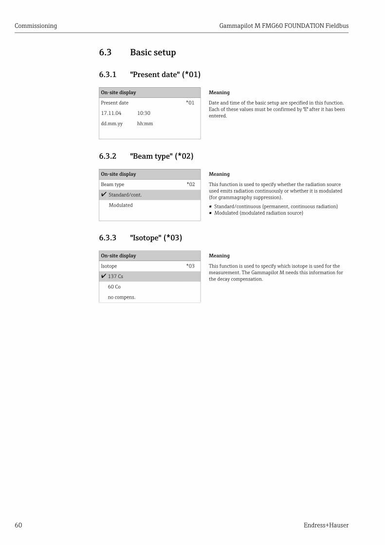
Commissioning Gammapilot M FMG60 FOUNDATION Fieldbus
60 Endress+Hauser
6.3 Basic setup
6.3.1 "Present date" (*01)
6.3.2 "Beam type" (*02)
6.3.3 "Isotope" (*03)
On-site display Meaning
Present date *01 Date and time of the basic setup are specified in this function. Each of these values must be confirmed by "E" after it has been entered.17.11.04 10:30
dd.mm.yy hh:mm
On-site display Meaning
Beam type *02 This function is used to specify whether the radiation source used emits radiation continuously or whether it is modulated (for grammagraphy suppression).
• Standard/continuous (permanent, continuous radiation)• Modulated (modulated radiation source)
Standard/cont.
Modulated
On-site display Meaning
Isotope *03 This function is used to specify which isotope is used for the measurement. The Gammapilot M needs this information for the decay compensation. 137 Cs
60 Co
no compens.

Gammapilot M FMG60 FOUNDATION Fieldbus Commissioning
Endress+Hauser 61
6.3.4 "Operating mode" (*04)
NOTICEThe selection can be performed only once and the function is automatically locked after that. It can only be unlocked again by a reset of the Gammapilot M ("Reset" (*A3) function).
A0018107
A One Gammapilot M is sufficient for measuring ranges up to 2 m (6.6 ft ); For larger measuring ranges as many Gammapilot M as required can be connected (cascading mode). By Software settings they are defined as
B MasterC Slave(s) orD End-Slave1 4 to 20 mA HART; PROFIBUS PA; FOUNDATION Fieldbus
Options/display:• Stand alone: This option is selected if the Gammapilot M is used as a single instrument.• Master: This option is selected if the Gammapilot is located at the beginning of a
cascading chain. It receives pulses from a connected slave, adds its own pulses and calculates the measuring value from this total.
• Slave: This option is selected if the Gammapilot M is located in the middle of a cascading chain. It receives the pulses from an additional connected slave or end-slave, adds its own pulses and transmits this total to the next device (master or slave). After selecting this option, the basic setup is finished. When cascading several transmitters the further calibration is performed on the master only.
• End slave: This option is selected if the Gammapilot M is located at the end of a cascading chain. It does not receive pulses from another device but transmits its own pulses to the next device (master or slave). After selecting this option, the basic setup is finished. When cascading several transmitters the further calibration is performed on the master only.
• Not defined: Is displayed if no operating mode has been selected yet. In order to continue the basic setup, a selection is necessary.
NOTICEIf a "Slave" or an "End-slave" are connected to the "FieldCare", the pulse rate of this device is displayed in the header instead of the measured value.
On-site display Meaning
Operating mode *04 This function is used to specify in which operating mode the Gammapilot M will be used. Stand alone
Master
Slave
A
B1
C
D

Commissioning Gammapilot M FMG60 FOUNDATION Fieldbus
62 Endress+Hauser
6.3.5 "Measurement mode" (*05)
Further options:• Level measurement (continuous)• Level limit detection• Density measurement (with temperature compensation if required)• Concentration measurement (density measurement followed by linearization)
NOTICEThe selection can be performed only once and the function is automatically locked after that. It can only be unlocked again by a reset of the Gammapilot M ("Reset" (*A3) function).
A0018108
A Level measurement (continuous) DensityB Level limit detection E ConcentrationC Density measurement (with temperature compensation if required)D Concentration measurement (density measurement followed by linearization)
On-site display Meaning
Meas. mode *05 This function is used to select the desired measuring mode.
Level
Limit
Density
A B
C D
�
E

Gammapilot M FMG60 FOUNDATION Fieldbus Commissioning
Endress+Hauser 63
6.3.6 "Density unit" (*06)
Further options:• g/cm3
• g/l• lb/gal; [1g/cm3 = 8,345 lb/gal]• lb/ft3; [1g/cm3 = 62,428 lb/ft3]• 1°Brix = [270 (1 - 1/x)]• °Baumé; [1°Baumé = 144.3 (1 - 1/x)]• °API; [1°API = 131.5 (1.076/x - 1)]• °Twaddell; [1°Twaddell = 200 (x-1)]
"x" refers to the density in g/cm3. The formula indicates how many degrees this density corresponds to.
6.3.7 "Min. density" (*07)
6.3.8 "Max. density" (*08)
6.3.9 "Pipe diameter unit" (*09)
On-site display Meaning
Density unit *06 This function is needed for density and concentration measure-ments only. It is used to select the density unit. g/cm3
g/l
lb/gal
On-site display Meaning
Min. density *07 This function is needed for density and concentration measure-ments only. It is used to specify the lower limit of the density range.0,9500 g/cm³
On-site display Meaning
Max. density *08 This function is needed for density and concentration measure-ments only. It is used to specify the upper limit of the density range.1,2500 g/cm³
On-site display Meaning
Pipe diam. unit *09 This function is needed for density and concentration measure-ments only. It is used to select the unit for the pipe diameter.
1 inch = 25,4 mm
mm
inch

Commissioning Gammapilot M FMG60 FOUNDATION Fieldbus
64 Endress+Hauser
6.3.10 "Pipe diameter" (*0A)
A0018109
Always specify the complete irradiated measuring path L in the "pipe diameter" (*0A) function. Depending on the installation, this value may be larger than the actual pipe diameter.
On-site display Meaning
Pipe diam. *0A This function is needed for density and concentration measure-ments only. It is used to specify the irradiated measuring path L. With standard installation, this value is identical to the inner pipe diameter DI. For other installations (in order to enlarge the irradiated measuring path) it may be larger (see figure). The pipe walls are not to be considered a part of the measuring path.
200 mm
1
1
1L
L
L
�DI
� L30° 2.0 x DI

Gammapilot M FMG60 FOUNDATION Fieldbus Commissioning
Endress+Hauser 65
6.3.11 "Output damping" (*0B)
A0018110
1 Level change (or density change)2 Measured value
Range of values1 to 999 s
DefaultThe default depends on the selected "measuring mode" (*05):• Level: 6 s• Limit: 6 s• Density: 60 s• Concentration: 60 s
Selecting the output dampingThe best value of the output damping depends on the process conditions. By enlarging the output damping, the measured value becomes considerably steadier but also slower.In order to dampen the influence of strongly fluctuating surfaces or stirrers, it is advisable to enlarge the output damping. On the other hand, if rapid changes of the measured value have to be detected accurately, the output damping may not be selected to large.
On-site display Meaning
Output damping *0B This function is used to specify the output damping (in seconds) by which changes of the measured value are attenua-ted.After a surge in the level or density it takes 5 x until the new measured value is reached.
60 s
5 x � t
L
1
2
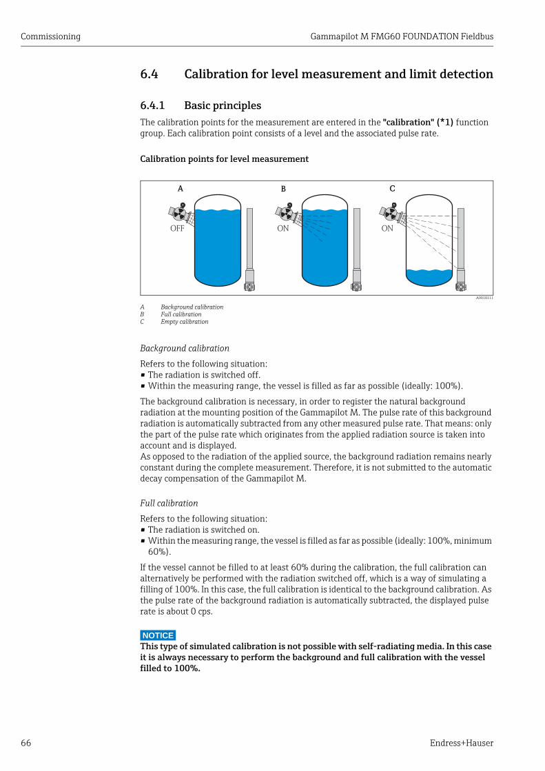
Commissioning Gammapilot M FMG60 FOUNDATION Fieldbus
66 Endress+Hauser
6.4 Calibration for level measurement and limit detection
6.4.1 Basic principlesThe calibration points for the measurement are entered in the "calibration" (*1) function group. Each calibration point consists of a level and the associated pulse rate.
Calibration points for level measurement
A0018111
A Background calibrationB Full calibrationC Empty calibration
Background calibration
Refers to the following situation:• The radiation is switched off.• Within the measuring range, the vessel is filled as far as possible (ideally: 100%).
The background calibration is necessary, in order to register the natural background radiation at the mounting position of the Gammapilot M. The pulse rate of this background radiation is automatically subtracted from any other measured pulse rate. That means: only the part of the pulse rate which originates from the applied radiation source is taken into account and is displayed.As opposed to the radiation of the applied source, the background radiation remains nearly constant during the complete measurement. Therefore, it is not submitted to the automatic decay compensation of the Gammapilot M.
Full calibration
Refers to the following situation:• The radiation is switched on.• Within the measuring range, the vessel is filled as far as possible (ideally: 100%, minimum
60%).
If the vessel cannot be filled to at least 60% during the calibration, the full calibration can alternatively be performed with the radiation switched off, which is a way of simulating a filling of 100%. In this case, the full calibration is identical to the background calibration. As the pulse rate of the background radiation is automatically subtracted, the displayed pulse rate is about 0 cps.
NOTICEThis type of simulated calibration is not possible with self-radiating media. In this case it is always necessary to perform the background and full calibration with the vessel filled to 100%.
CBA
OFF ON ON

Gammapilot M FMG60 FOUNDATION Fieldbus Commissioning
Endress+Hauser 67
Empty calibration
Refers to the following situation:• The radiation is switched on.• Within the measuring range, the vessel is emptied as far as possible (ideally: 0%,
maximum 40%).
Calibration points for limit detection
A0018112
A Background calibrationB Covered calibrationC Free calibration
Background calibration
Refers to the following situation:• The radiation is switched off.• If possible, the radiation path is completely covered.
The background calibration is necessary, in order to register the natural background radiation at the mounting position of the Gammapilot M. The pulse rate of this background radiation is automatically subtracted from any other measured pulse rate. That means: only the part of the pulse rate which originates from the applied radiation source is taken into account and is displayed.As opposed to the radiation of the applied source, the background radiation remains nearly constant during the complete measurement. Therefore, it is not submitted to the automatic decay compensation of the Gammapilot M.
Covered calibration
Refers to the following situation:• The radiation is switched on.• If possible, the radiation path is completely covered.
If the radiation path cannot be completely covered during the calibration, the covered calibration can alternatively be performed with the radiation switched off, which is a way of simulating complete covering. In this case, the covered calibration is identical to the background calibration. As the pulse rate of the background radiation is automatically subtracted, the displayed pulse rate is about 0 c/s.
NOTICEThis type of simulated calibration is not possible with self-radiating media. In this case it is always necessary to perform the background calibration and the covered calibration with the radiation path completely covered.
Free calibration
Refers to the following situation:• The radiation is switched on.• The radiation path is completely free.
A B C
OFF ON ON

Commissioning Gammapilot M FMG60 FOUNDATION Fieldbus
68 Endress+Hauser
Methods for entering the calibration points
Automatic calibration
For an automatic calibration, the vessel is filled to the required value. For the background calibration the radiation remains switched off, for the other calibration points the radiation is switched on.The Gammapilot M automatically records the pulse rate. The associated level is entered by the user.
Manual calibration
If during the commissioning of the Gammapilot M one or more calibration points cannot be realized (e.g. because the vessel cannot be sufficiently filled or emptied), the calibration point must be entered manually.That is, not only the level but also the associated pulse rate must be entered by the user. For details concerning the calculation of the count rate please refer to your Endress+Hauser sales organization.
NOTICECalibration date and calibration‣ When calibrating manually, the calibration date is not set automatically. Instead, it must
be entered manually into the "calibration date" (*C7) function.‣ A manually entered calibration point should be replaced by an automatic calibration as
soon as the associated level occurs during the operation of the plant. This recalibration is advisable because calibration points entered automatically result in more precise measurement results than calculated ones.

Gammapilot M FMG60 FOUNDATION Fieldbus Commissioning
Endress+Hauser 69
6.4.2 Background calibration
Excerpt from the operating menu
The following excerpt from the operating menu shows how the background calibration is entered. The individual functions are explained in the sections below.
"Background calibration" (*10)
Options:• stop/edit This option must be selected if
– No background calibration is to be performed but the pulse rate of an existing background calibration is to be displayed instead.
– A manual background calibration is to be performed.After selecting this option, the Gammapilot M changes to the "bgr. pulse rate" (*12) function, where the existing pulse rate is displayed and can be changed if required.
• start This option is used to start an automatic background calibration. The Gammapilot M changes to the "avg. pulse rate" (*11) function.
*10Backgr. calibr.0: stop/edit1: start
*11avg. pulse rate
*10bgr. pulse rate
-1: not calibrated
On-site display Meaning
Backgr. cal. *10 This function is used to start the background calibration.
Stop/edit
Start
E
E
0

Commissioning Gammapilot M FMG60 FOUNDATION Fieldbus
70 Endress+Hauser
"Avg. pulse rate" (*11)
A0018118
If the value is sufficiently stable, the function can be left by pressing "E".Thereafter, the Gammapilot M changes to the "backgr. calib." (*10) function. Select "stop/edit" to stop the averaging procedure. The value is then automatically transmitted to the "bgr. pulse rate" (*12) function.
NOTICEBgr. Pulse rate‣ The maximum integration time is 1000 s. After this time, the value is automatically
transmitted to the "bgr. pulse rate" (*1B) function.‣ The integration is not terminated by pressing "E" in the "avg. pulse rate" (*11) function.
It is continued until the selection of "stop/edit" in the "backgr. calib." (*10) function. This may result in a slight deviation between the last displayed average pulse rate and the final "bgr. pulse rate" (*12).
"Background pulse rate" (*12)
On-site display Meaning
Avg. pulse rate *11 The average pulse rate is displayed in this function (after selec-tion of "start" in the previous function). Initially, this value fluc-tuates (because of the decay statistics), but due to the integra-tion it reaches an average value in the course of time. The longer the averaging is performed the lower are the remaining fluctuations.
186 cps
c/s
t
"E"
On-site display Meaning
Backgr. pulse rate *12 The pulse rate of the background calibration is displayed in this function. By pressing "E" the displayed value can be confirmed and the background calibration completed. "-1" indicates, that no background calibration is present yet. In this case there are two options:• Either return to the "background calibration" (*10) func-
tion and restart the background calibration• Or enter a known or calculated pulse rate (manual calibra-
tion). Thereafter, the Gammapilot M changes to the "calibr. point" (*13) or (*1A) function.
186 cps

Gammapilot M FMG60 FOUNDATION Fieldbus Commissioning
Endress+Hauser 71
6.4.3 Full and empty calibration or covered and free calibration
Excerpt from the operating menu
The following excerpt from the operating menu shows how the full and empty calibration (for level measurements) or the covered and free calibration (for level limit detection) are entered. The individual functions are explained in the sections below.The functions are only accessible after the background calibration has been performed.
NOTICEThe "value full" (*14) and "value empty" (*17) functions only appear if the "level" option was selected in the "measurement method" function (*05).
"Calibration point" (*13)
*14value full[%]target value at calibr. point
*15calibration0: stop/edit1: start
*11avg. pulse rate
*16full calibr.[c/s]-1: not calibra-ted
Group selection
013calibr. point0: full/covered1: empty/free
*19next point0: no1: yes
*17value empty[%]target value at calibr. point
*15calibration0: stop/edit1: start
*11avg. pulse rate
*18empty calibr.[c/s]-1: not calibra-ted
On-site display Meaning
Calibr. point *13 This function is used to select which calibration point ("full/covered" or "empty/free") will be entered. full/covered
empty/free
1
E0
1
E0

Commissioning Gammapilot M FMG60 FOUNDATION Fieldbus
72 Endress+Hauser
"Value full" (*14) / "Value empty" (*17)
Range of values
"Calibration start stop" (*15)
Options:• stop/edit
This option must be selected if– the calibration point is not to be entered (e.g. because it has already been entered). The
pulse rate of the calibration point is then displayed in the following function, "full calibr." (*16) or "empty calibr." (*18). If required, this value can be changed.
– the calibration point is to be entered manually. This can be done in the following function, "full calibr." (*16) or "empty calibr." (*18).
• start This option is used to start the automatic entering of the calibration point. The Gammapilot M then changes to the "avg. pulse rate" (*11) function.
On-site display Meaning
value full *14 These functions are needed for level measurements only. They are used to specify the level at which the full or empty calibration are performed.100%
value empty *17
0%
optimum value minimum value maximum value
Value full (*14) 100% 60% 100%
Value empty (*17) 0% 0% 40%
On-site display Meaning
calibration *15 This function is used to start the automatic entering of the selected calibration point.
stop/edit
start

Gammapilot M FMG60 FOUNDATION Fieldbus Commissioning
Endress+Hauser 73
"Avg. pulse rate" (*11)
A0018118
Initially, the pulse rate strongly fluctuates. In the course of time an average value is reached.
If the value is sufficiently stable, the function can be left by pressing "E".Thereafter, the Gammapilot M changes to the "calibration" (*15) function. Select "stop/edit" to stop the averaging procedure. The value is then automatically transmitted to the "full calibr." (*16) or "empty calibr." (*18) function respectively.
NOTICEAvg. Pulse rate‣ The maximum integration time is 1000 s. The value is then transmitted automatically to
the "full calibr." (*16) or "empty calibr." (*18) function.‣ The integration is not terminated by pressing "E" in the "avg. pulse rate" (*11) function.
It is continued until the selection of "stop/edit" in the "calibration" (*15) function. This may result in a slight deviation between the last displayed average pulse rate and the final "full calibr." (*16) or "empty calibr. (*18).
"Full calibration" (*16) / "Empty calibration" (*18)
On-site display Meaning
avg. pulse rate *11 The average pulse rate is displayed in this function (after selection of "start" in the previous function). Initially, this value fluctuates (because of the decay statistics), but due to the integration it reaches an average value in the course of time. The longer the averaging is performed the lower are the remaining fluctuations.
2548 cps
c/s
t
"E"
On-site display Meaning
full calibr. *16 The pulse rate of the respective calibration points is displayed in these functions. The displayed value must be confirmed by pressing "E". "-1" indicates, that no background calibration is present yet. In this case there are two options:• either return to the "calibration" (*15) function and restart
the calibration• or enter a knwon or calculated pulse rate (manual
calibration)
33 cps
empty calibr. *18
2548 cps

Commissioning Gammapilot M FMG60 FOUNDATION Fieldbus
74 Endress+Hauser
"Next point" (*19)
Options:• no
This option must be selected after both calibration points have been entered. After this selection the Gammapilot M returns to the group selection and the calibration is completed.
• yes This option must be selected, if only one calibration point has been entered yet. After this selection the Gammapilot M returns to the "calibr. point" (*13) function and the next point can be entered.
6.4.4 Additional settingsAfter the calibration, the Gammapilot M outputs the measured value via the Foundation Fieldbus interface.Many additional functions are available for optimizing the measuring point. They can be configured as required. A detailed description of all instrument functions is given in Operating Instructions BA00287F/00/EN, "Gammapilot M - Description of Device Functions". This document can be found on the supplied CD-ROM.
On-site display Meaning
next point *19 This function is used to specify, if a further calibration point is to be entered or not. no
yes

Gammapilot M FMG60 FOUNDATION Fieldbus Commissioning
Endress+Hauser 75
6.5 Calibration for density and concentration measurements
6.5.1 Basic principlesThe calibration points for the measurement are entered in the "calibration" (*1) function group. Each calibration point consists of a density value and the associated pulse rate.
Calibration points for density and concentration measurements
Function of the calibration points
For density and concentration measurements the Gammapilot M needs (apart from the length of the irradiated measuring path) the following two parameters:• The absorption coefficient of the material measured• The reference pulse rate I0
9).
It calculates these parameters automatically from the following calibration points:• Background calibration (calibration with the radiation switched off)• Up to nine calibration points for samples of various known densities.
NOTICEWith self-radiating media it is always necessary to perform the background calibration with a filled pipe. A simulated calibration with an empty pipe is not possible in this case.
A0018128
0 Background calibration1-9 Calibration points for various densities
Two-point calibration
The recommended comparisen procedure for high exactness standards about the whole measuring range is the two-point calibration. First the background calibration occurs. The two calibration points will be adapt. They should lie differ considerably. After input of both calibration points, the Gammapilot M calculates the parameters I0 und .
One-point calibration
If a two-point calibration is not possible, a one-point calibration can be carried out. That means, that apart from the background calibration only one further calibration point is used. This calibration point should be located as near as possible to the operating point. Densities in the proximity of this operating point are measured fairly precisely, whereas the precision may decrease with increasing distance to the operating point.In one-point calibration, the Gammapilot M only calculates the reference pulse rate I0. For the absorption coefficient it uses the standard value = 7.7 mm2/g in this instance.
9) I0 is the pulse rate for the tube being empty. The value is significantly higher than any real pulse rate occurring during the measurement.
OFF ON
0 1 9

Commissioning Gammapilot M FMG60 FOUNDATION Fieldbus
76 Endress+Hauser
Multiple-point calibration
The multiple-point calibration is recommended particularly for measurements in a large density area or for especially exact measurements. Up to 9 calibration points can be used about the whole measuring range. The calibration points should be located as far from each other as possible and should be uniformly distributed over the measuring range. After the calibration points have been entered, the Gammapilot M automatically calculates the parameters I0 and . Multiple-point calibration is especially advisable for measurement in a wide range of densities or for especially precise measurements.
Recalibration
The Gammapilot M provides a further calibration point ("10") for recalibration. This point can be entered, if the measuring conditions have changed, e.g. by deposit in the measuring tube. After entering of the recalibration point, I0 is recalculated according to the current measuring conditions. The absorption coefficient is kept unchanged from the original calibration.
Methods for entering the calibration points
Automatic calibration
For an automatic calibration, the desired calibration point is realized at the measuring tube, i.e. the measuring tube is filled with a medium of the desired density. For the background calibration the radiation remains switched off, for the other calibration points the radiation is switched on.The Gammapilot M automatically records the pulse rate. The associated density is determined in the laboratory and entered by the user.
Manual calibration
In order to achieve a high measuring accuracy, it is advisable to determine the pulse rates for a couple of samples of the same density and to calculate the average density and average pulse rate for these samples. These values can then be entered manually into the Gammapilot M.If possible, this procedure should be repeated at a further density. The both density values should be as far from each other as possible.
NOTICEWhen calibrating manually, the calibration date is not set automatically. Instead, it must be entered manually into the "calibration date" (*C7) function.

Gammapilot M FMG60 FOUNDATION Fieldbus Commissioning
Endress+Hauser 77
6.5.2 Background calibration
Excerpt from the operating menu
The following excerpt from the operating menu shows how the background calibration is entered. The individual functions are explained in the sections below.
"Background calibration" (*10)
Options:• stop/edit
This option must be selected if– no background calibration is to be performed but the pulse rate of an existing
background calibration is to be displayed instead.– a manual background calibration is to be performed.After selecting this option, the Gammapilot M changes to the "bgr. pulse rate" (*12) function, where the existing pulse rate is displayed and can be changed if required.
• start This option is used to start an automatic background calibration. The Gammapilot M changes to the "avg. pulse rate" (*11) function.
*10backgr. calib.0: stop/edit1: start
*11avg. pulse rate
*12bgr. pulse rate
-1: not calibrated
On-site display Meaning
backgr. cal. *10 This function is used to start the background calibration.
stop/edit
start
E
1 E
0

Commissioning Gammapilot M FMG60 FOUNDATION Fieldbus
78 Endress+Hauser
"Avg. pulse rate" (*11)
A0018118
If the value is sufficiently stable, the function can be left by pressing "E".Thereafter, the Gammapilot M changes to the "backgr. calib." (*10) function. Select "stop/edit" to stop the averaging procedure. The value is then automatically transmitted to the "bgr. pulse rate" (*12) function.
NOTICEBgr. Pulse rate‣ The maximum integration time is 1000 s. After this time, the value is automatically
transmitted to the "bgr. pulse rate" (*1B) function.‣ The integration is not terminated by pressing "E" in the "avg. pulse rate" (*11) function.
It is continued until the selection of "stop/edit" in the "backgr. calib." (*10) function. This may result in a slight deviation between the last displayed average pulse rate and the final "bgr. pulse rate" (*12).
"Background pulse rate" (*12)
On-site display Meaning
avg. pulse rate *11 The average pulse rate is displayed in this function (after selec-tion of "start" in the previous function).Initially, this value fluctuates (because of the decay statistics), but due to the integration it reaches an average value in the course of time. The longer the averaging is performed the lower are the remaining fluctuations.
186 cps
c/s
t
"E"
On-site display Meaning
backgr. pul. rate *12 The pulse rate of the background calibration is displayed in this function. By pressing "E" the displayed value can be confirmed and the background calibration completed. "-1" indicates, that no background calibration is present yet. In this case there are two options:• either return to the "background calibration" (*10)
function and restart the background calibration• or enter a known or calculated pulse rate (manual
calibration). Thereafter, the Gammapilot M changes to the "calibr. point" (*13) or (*1A) function
186 cps

Gammapilot M FMG60 FOUNDATION Fieldbus Commissioning
Endress+Hauser 79
6.5.3 Calibration points
Excerpt from the operating menu
The following excerpt from the operating menu shows, how the density calibration points are entered. The individual functions are explained in the sections below.The functions are only accessible after the background calibration has been performed.
"Calibration point" (*1A)
Further options:• "1" to "9" : Calibration points for various densities• "10": recalibration point
After entering of the recalibration point, I0 is recalculated according to the current measuring conditions. The absorption coefficient is kept unchanged from the original calibration.The calibration point "10" can be entered if the measuring conditions have changed, e.g. due to buildup in the measuring tube.
*1Acalibr. point1...9point 10 for recalibration
*15calibration0: stop/edit1: start
*11avg. pulserate
*1Bdensity calib.(c/s)
*1Cdensity value
Group selection
*1Dcalibr. point0: not used1: used2: clear
*1Eabsorp. coeff.
*1Fref. pulse rate
*19next point0: no1: yes
On-site display Meaning
calibr. point *1A This function is used to select, which calibration point will be entered. 1
2
3
E0
1
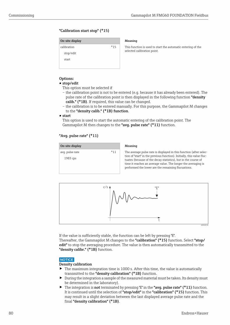
Commissioning Gammapilot M FMG60 FOUNDATION Fieldbus
80 Endress+Hauser
"Calibration start stop" (*15)
Options:• stop/edit
This option must be selected if– the calibration point is not to be entered (e.g. because it has already been entered). The
pulse rate of the calibration point is then displayed in the following function "density calib." (*1B). If required, this value can be changed.
– the calibration is to be entered manually. For this purpose, the Gammapilot M changes to the "density calib." (*1B) function.
• start This option is used to start the automatic entering of the calibration point. The Gammapilot M then changes to the "avg. pulse rate" (*11) function.
"Avg. pulse rate" (*11)
A0018118
If the value is sufficiently stable, the function can be left by pressing "E".Thereafter, the Gammapilot M changes to the "calibration" (*15) function. Select "stop/edit" to stop the averaging procedure. The value is then automatically transmitted to the "density calibr." (*1B) function.
NOTICEDensity calibration‣ The maximum integration time is 1000 s. After this time, the value is automatically
transmitted to the "density calibration" (*1B) function.‣ During the integration a sample of the measured material must be taken. Its density must
be determined in the laboratory).‣ The integration is not terminated by pressing "E" in the "avg. pulse rate" (*11) function.
It is continued until the selection of "stop/edit" in the "calibration" (*15) function. This may result in a slight deviation between the last displayed average pulse rate and the final "density calibration" (*1B).
On-site display Meaning
calibration *15 This function is used to start the automatic entering of the selected calibration point.
stop/edit
start
On-site display Meaning
avg. pulse rate *11 The average pulse rate is displayed in this function (after selec-tion of "start" in the previous function). Initially, this value fluc-tuates (because of the decay statistics), but in the course of time it reaches an average value. The longer the averaging is performed the lower are the remaining flucuations.
1983 cps
c/s
t
"E"

Gammapilot M FMG60 FOUNDATION Fieldbus Commissioning
Endress+Hauser 81
"Density calibration" (*1B)
"Density value" (*1C)
NOTICEWhen entering the value, temperature influences have to be taken into account. The density entered must refer to the temperature at which the pulse rate has been determined. If the density and the pulse rate have been determined at different temperatures, the density value must be corrected accordingly.
"Calibration point" (*1D)
Options:• not used
The calibration point is not used. However, it can be reactivated at a later point of time.• used
The calibration point is used.• clear
The calibration point is deleted. It cannot be reactivated at a later point of time.
On-site display Meaning
density calibr. *1B The pulse rate of the respective calibration point is displayed in this function. The display value must be confirmed by pressing "E". "-1" indicates, that no pulse rate is present yet. In this case there are two options:• either return to the "calibration" (*15) function and restart
the calibration• or enter a known or calculated pulse rate (manual calibra-
tion)
1983 cps
On-site display Meaning
density value *1C This function is used to enter the density of the calibration point. The value must be determined from the sample in a laboratory measurement.0.9963 g/cm3
On-site display Meaning
calibr. point *1D This function is used to specify, if the current calibration piont is to be used.
not used
used
clear

Commissioning Gammapilot M FMG60 FOUNDATION Fieldbus
82 Endress+Hauser
"Absorption coefficient" (*1E)
NOTICEIf only one calibration point is currently active, the absorption coefficient is not calculated. The last valid value is used instead. At the first commissioning or after a reset, the default value, = 7.70 mm2/g, is used. The value can be changed by the user.
"Reference pulse rate" (*1F)
NOTICEI0 is the pulse rate for the tube being empty (theoretical reference value). Generally, the value is significantly higher than any real pulse rate occurring during the measurement.
"Next point" (*19)
Options:• no
This option must be selected if no further calibration point is to be entered or changed. After this selection the Gammapilot M returns to the group selection and the calibration is completed.
• yes This option must be selected, if a further calibration point is to be entered or changed. The Gammapilot M returns to the "calibr. point" (*1A) function and the next point can be entered or changed.
On-site display Meaning
absorp. coeff. *1E This function displays the absorption coefficient which results from the currently active calibration points. The displayed value should be used for plausibility checking.7.70 mm2/g
On-site display Meaning
ref. pulse rate *1F This function displays the reference pulse rate IO, which results from the currently active calibration points. The value cannot be edited.31687 cps
On-site display Meaning
next point *19 This function is used to specify, if a further calibration point is to be entered or not. no
yes
Gammapilot M FMG60 FOUNDATION Fieldbus Commissioning
Endress+Hauser 83
6.5.4 Linearization (for concentration measurements)If the concentration is to be measured in a unit other than the "density unit" (*06), a linearization must be performed after the calibration. This can be done in the "Linearization" (*4) function group. The functions of this group and the linearization procedure are described in Operating Instructions BA00287F/00/EN, "Gammapilot M - Description of Device Functions". This document can be found on the supplied CD-ROM.
6.5.5 Additional settingsAfter the calibration, the Gammapilot M outputs the measured value via the FOUNDATION Fieldbus interface.Many additional functions are available for optimizing the measuring point. They can be configured as required. A detailed description of all instrument functions is given in Operating Instructions BA00287F/00/EN, "Gammapilot M - Description of Device Functions". This document can be found on the supplied CD-ROM.
6.6 Density measurement/temperature-compensatedPerform density measurement as described in the section "Calibration for density and concentration measurements" and then perform temperature calibration (see "Temperature compensation" section in BA00287F/00/EN "Gammapilot M - Description of Device Functions").
6.7 Gammagraphy detectionSee "Gammagraphy" section in BA00287F/00/EN "Gammapilot M - Description of Device Functions".

Maintenance and repairs Gammapilot M FMG60 FOUNDATION Fieldbus
84 Endress+Hauser
7 Maintenance and repairs
7.1 Exterior cleaningWhen cleaning the exterior, always use cleaning agents that do not attack the surface of the housing and the seals.
7.2 RepairThe Endress+Hauser repair concept assumes that repairs to the Gammapilot M are performed by the Endress+Hauser Service in Endress+Hauser workshops.For more information contact the Service Department at Endress+Hauser.
7.3 Repairs to Ex-approved devicesWhen carrying out repairs to Ex-approved devices, please note the following:• Repairs to Ex-approved devices may only be carried out by Endress+Hauser Service in
Endress+Hauser workshops.• Comply with the prevailing standards, national Ex-area regulations, safety instructions
(XA) and certificates.• Only use original spare parts from Endress+Hauser.• A certified device may only be converted into a different certified device version by
Endress+Hauser Service in Endress+Hauser workshops.• Document all repair work and conversions.
7.4 ReplacementCAUTION!
An uploading/download procedure is not permitted for safety-related use of the device.
After a complete device or electronic module has been replaced, the parameters can be downloaded into the device again via the communication interface. As a prerequisite, the data have to have been uploaded to the PC beforehand using the "FieldCare".
Level measurement and level limit detectionMeasurement can be continued without a new setup. However, the calibration values should be checked as soon as possible, since the mounting position may have slightly changed.
Density and concentration measurementAfter the replacement a new setup and calibration must be performed.

Gammapilot M FMG60 FOUNDATION Fieldbus Maintenance and repairs
Endress+Hauser 85
7.5 Return
7.5.1 Returning devicesThe measuring device must be returned if repairs of a factory calibration are required, or if the wrong measuring device has been ordered or delivered. According to legal regulations, Endress+Hauser, an ISO-certified company, is required to follow certain procedures when handling returned products that are in contact with medium.
To ensure swift, safe and professional device returns, please read the return procedures and conditions on the Endress+Hauser website at www.services.endress.com/return-material
7.6 DisposalWhen disposing, separate and recycle the device components based on the materials.
7.7 Contact addresses of Endress+HauserContact addresses can be found on our homepage: www.endress.com/worldwide. If you have any questions, please contact your Endress+Hauser subsidiary.

Accessories Gammapilot M FMG60 FOUNDATION Fieldbus
86 Endress+Hauser
8 Accessories
8.1 Commubox FXA291The Commubox FXA291 connects Endress+Hauser field devices with a CDI interface (Endress+Hauser Common Data Interface) and the USB port of a computer or laptop. For details, see TI00405C/07/EN.
For Gammapilot M, you also need the "ToF adapter FXA291" accessory.
8.2 ToF adapter FXA291The ToF adapter FXA291 connects the Commubox FXA291 with the Gammapilot M by means of the USB port of a computer or laptop. For details, see KA00271F/00/A2.
8.3 Field Xpert SFX100Compact, flexible and robus industry handheld terminal for remote parametrization and measured value inspection via the HART current output or FOUNDATION Fieldbus. For details refer to Operating Instructions BA00060S/04/EN.

Gammapilot M FMG60 FOUNDATION Fieldbus Accessories
Endress+Hauser 87
8.4 Remote display FHX40
8.4.1 Dimensions
A0018138
A Wall-mounting (without mounting bracket) 1 Gammapilot M 3 CableB Pipe-mounting (mounting bracket and plate supplied optionally) 2 Separat housing FHX40 4 Pipe
8.4.2 Ordering information
Use the cables provided for the corresponding communication version of the device to connect the remote display FHX40.
82 (3.23)
mm (in)
6.3 (0
.25)
10
6 (
4.1
7)
12
2 (
4.8
)
120 (4.72)
max. 80 (3.15)min. 30 (1.18)
96 (3.78)
16
0 (
6.3
)
8.5 (0
.33)
118 (4.65)
18
0 (
7.0
9)
1
2
3
h
b
t
A B
4
88(3.46)
010 ApprovalA Non-hazardous area2 ATEX II 2G Ex ia IIC T63 ATEX II 2D Ex ia IIIC T80°CH ATEX II 3G Ex ic IIC T6, T5 Gc (in preparation)G IECEx zone1 Ex ia IIC T6/T5S FM IS Cl.I Div.1 Gr.A-D, zone 0U CSA IS Cl.I Div.1 Gr.A-D, zone 0N CSA General PurposeK TIIS Ex ia IIC T6C NEPSI Ex ia IIC T6/T5 GbY Special version, TSP-no. to be spec.
020 Cable1 20m/65ft (> HART)5 20m/65ft (> PROFIBUS PA/FOUNDATION Fieldbus)9 Special version, TSP-no. to be spec.
030 Additional OptionA Basic versionB Mounting bracket, pipe 1"/ 2"Y Special version, TSP-no. to be spec.
995 Marking1 Tagging (TAG), see additional spec.
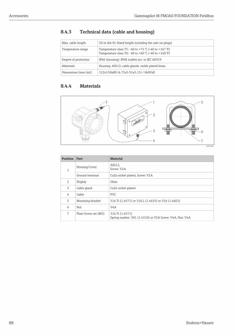
Accessories Gammapilot M FMG60 FOUNDATION Fieldbus
88 Endress+Hauser
8.4.3 Technical data (cable and housing)
8.4.4 Materials
A0019282
Max. cable length 20 m (66 ft) (fixed length including the cast-on plugs)
Temperature range Temperature class T5: -40 to +75 °C (-40 to +167 °F)Temperature class T6: -40 to +60 °C (-40 to +140 °F)
Degree of protection IP66 (housing); IP68 (cable) acc. to IEC 60529
Materials Housing: AlSi12; cable glands: nickle plated brass
Dimensions [mm (in)] 122x150x80 (4.72x5.91x3.15) / HxWxD
Position Part Material
1Housing/Cover
AlSi12,Screw: V2A
Ground terminal CuZn nickel-plated, Screw: V2A
2 Display Glass
3 Cable gland CuZn nickel-plated
4 Cable PVC
5 Mounting bracket 316 Ti (1.4571) or 316 L (1.4435) or 316 (1.4401)
6 Nut V4A
7 Plate Screw set (M5) 316 Ti (1.4571) Spring washer: 301 (1.4310) or V2A Screw: V4A, Nut: V4A
Ma
de
in
Ge
rM
ad
e in
Ge
rma
nm
an
y
M
au
lby
M
au
lbu
rgu
rg
4
1
2
3 6
7
53

Gammapilot M FMG60 FOUNDATION Fieldbus Accessories
Endress+Hauser 89
8.5 Mounting device FHG60 (for level measurement and level limit measurement)
8.5.1 Dimensions
A0018139
1 Spacing as large as possible2 Retainers (number and size depending on selected application ); Allen screws to ISO 4762 are supplied)3 Mounting clamps (number depending on selected application ))4 with preferred mounting method "housing head down" - bracket (for "level" application only 10))5 with alternative mounting method "housing head up" - bracket (for "level" application only ))
Size of the retainers (depending on the selected application):
CAUTION!
Max. torque for the screws of the retainers: 6 Nm (4.42 lbf ft).
M6x20-A2
M6x80-A2
2
3 B
40
(1
.57
)
70
(2
.76
)
70
(2
.76
)
19
0 (
7.4
8)
88 (3.46)
116 (4.57)
mm (in)
#max. 6 Nm(4.42 lbf ft)
1
4 5
88 (3.46)
35
(1
.38
)
A
øD
øC
63 (2.48)
35
(1
.38
)1
10
(4
.33
)23
0 (
9.0
6)
10) See "Use" and "Ordering information for complete mounting set".
Mounting position at the FMG60
A [mm (in)] B [mm (in)] øC [mm (in)] øD [mm (in)] Mounting
Scintillator pipe dimensions 196 (7.72) 126 (4.96) 80 (3.15)
40 to 65(1.57 to 2.56)
(a)
Electronic pipe dimensions 210 (8.27) 150 (5.91) 102 (4.02) (b)
Water cooling jacket dimensions
230 (9.06) 200 (7.87) 140 (5.51) (c)
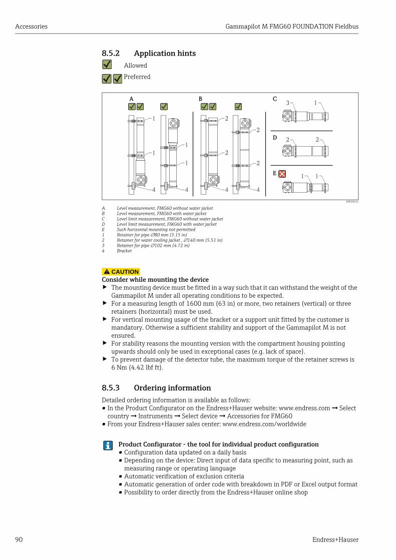
Accessories Gammapilot M FMG60 FOUNDATION Fieldbus
90 Endress+Hauser
8.5.2 Application hints Allowed
Preferred
A0018141
A Level measurement, FMG60 without water jacketB Level measurement, FMG60 with water jacketC Level limit measurement, FMG60 without water jacketD Level limit measurement, FMG60 with water jacketE Such horizontal mounting not permitted1 Retainer for pipe 80 mm (3.15 in)2 Retainer for water cooling jacket , 140 mm (5.51 in)3 Retainer for pipe 102 mm (4.72 in)4 Bracket
CAUTION!
Consider while mounting the device‣ The mounting device must be fitted in a way such that it can withstand the weight of the
Gammapilot M under all operating conditions to be expected. ‣ For a measuring length of 1600 mm (63 in) or more, two retainers (vertical) or three
retainers (horizontal) must be used.‣ For vertical mounting usage of the bracket or a support unit fitted by the customer is
mandatory. Otherwise a sufficient stability and support of the Gammapilot M is not ensured.
‣ For stability reasons the mounting version with the compartment housing pointing upwards should only be used in exceptional cases (e.g. lack of space).
‣ To prevent damage of the detector tube, the maximum torque of the retainer screws is 6 Nm (4.42 lbf ft).
8.5.3 Ordering informationDetailed ordering information is available as follows:• In the Product Configurator on the Endress+Hauser website: www.endress.com ➞ Select
country ➞ Instruments ➞ Select device ➞ Accessories for FMG60• From your Endress+Hauser sales center: www.endress.com/worldwide
1 2
2
3
2 2
1
1 1
2
21
4 4 4 4
1
1
A B C
D
E
Product Configurator - the tool for individual product configuration• Configuration data updated on a daily basis• Depending on the device: Direct input of data specific to measuring point, such as
measuring range or operating language• Automatic verification of exclusion criteria• Automatic generation of order code with breakdown in PDF or Excel output format• Possibility to order directly from the Endress+Hauser online shop

Gammapilot M FMG60 FOUNDATION Fieldbus Accessories
Endress+Hauser 91
8.6 Clamping device for density measurement FHG61For details, see SD01221F/00/EN.
8.7 Measurement section for density measurement FHG62
For drawings and description, see SD00540F/00/EN.
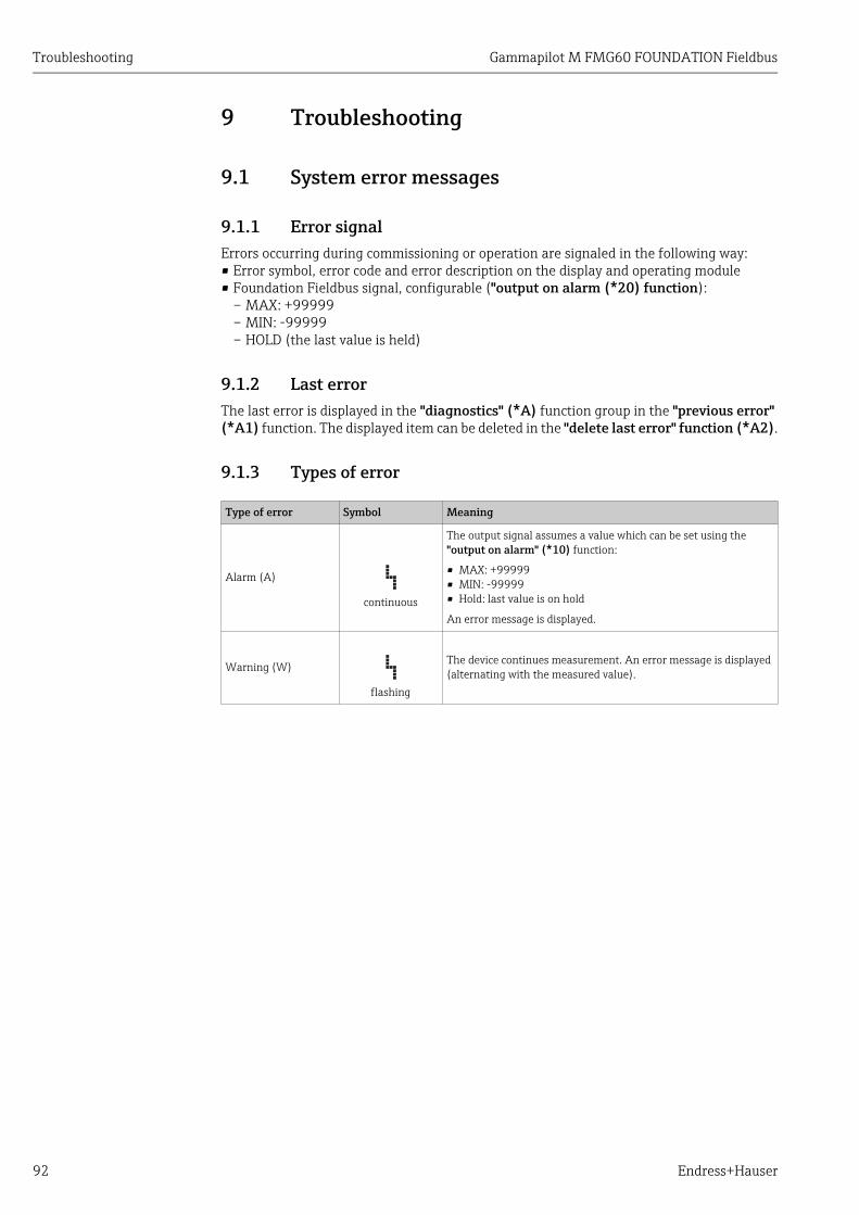
Troubleshooting Gammapilot M FMG60 FOUNDATION Fieldbus
92 Endress+Hauser
9 Troubleshooting
9.1 System error messages
9.1.1 Error signalErrors occurring during commissioning or operation are signaled in the following way:• Error symbol, error code and error description on the display and operating module• Foundation Fieldbus signal, configurable ("output on alarm (*20) function):
– MAX: +99999– MIN: -99999– HOLD (the last value is held)
9.1.2 Last errorThe last error is displayed in the "diagnostics" (*A) function group in the "previous error" (*A1) function. The displayed item can be deleted in the "delete last error" function (*A2).
9.1.3 Types of error
Type of error Symbol Meaning
Alarm (A)
continuous
The output signal assumes a value which can be set using the "output on alarm" (*10) function:
• MAX: +99999• MIN: -99999• Hold: last value is on hold
An error message is displayed.
Warning (W)
flashing
The device continues measurement. An error message is displayed (alternating with the measured value).

Gammapilot M FMG60 FOUNDATION Fieldbus Troubleshooting
Endress+Hauser 93
9.1.4 Error codes
Code Description Remedy
A102 checksum error call Endress+Hauser Service
W103 initializing wait for completion of the initializing procedure
A106 downloading wait for completion of the download
A110 checksum error call Endress+Hauser Service
A111 electronics defect switch device off/on;if error still is present: call Endress+Hauser service or exchange transmitter
A113 electronics defect switch device off/on;if error still is present: call Endress+Hauser service or exchange transmitter
A114 electronics defect switch device off/on;if error still is present: call Endress+Hauser service or exchange transmitter
A116 download error repeat download
A121 electronics defect switch device off/on;if error still is present: call Endress+Hauser service or exchange transmitter
W153 initializing wait for completion of the initializing procedure
A160 checksum error call Endress+Hauser Service
A165 electronics defect • Switch instrument off/on;If error still is present: call Endress+Hauser service or exchange transmitter
• See Note "Error messages A165 "electronics defect" and A635 "present date not defined" on ä 59.
A291 slave error check basic setup and connection of the slave transmitter
A503 wrong sensor type call Endress+Hauser Service
W513 calibration integration running Wait, until a stable pulse rate has been reached; then, terminate integration (by pressing "E" in the "average pulse rate" (*11) function)
W514 PT-100 calibration wait for the calibration to complete.if error still persists: call Endress+Hauser Service
A531 sensor electronics defect switch device off/on;if error still is present: call Endress+Hauser service or exchange transmitter
A532 sensor voltage error call Endress+Hauser Service
A533 wrong sensor software version call Endress+Hauser Service
A535 sensor regulation error call Endress+Hauser Service
W536 high voltage near limit call Endress+Hauser Service
A538 sensor communication error call Endress+Hauser Service
A602 linearization table not plausible check monotony of the linearization table; if necessary, adjust table ("linearization" (*4) function group)
A612 linearization table not defined enter or complete linearization table( "linearization" (*4) function group)The linearization table must contain the end points 0% = 1000 cps (standardized) and 100% = 0 cps (standardized).When entering via FieldCare:Select the right type of table (lin. tab. "level" or "concentration")
W621 simulation on Switch off linearization("output" (*6) function group"simulation" (*65) function)

Troubleshooting Gammapilot M FMG60 FOUNDATION Fieldbus
94 Endress+Hauser
W640 SIL lock device SIL_locking not completed
W642 I_back calibration running calibration of the current readback path active
A631 background not calibrated perform background calibration("calibration" (*1) function group)
A632 full/covered not calibrated perform full/covered calibration("calibration" (*1) function group)
A633 empty/free not calibrated perform empty/free calibration("calibration" (*1) function group)
A634 density not calibrated • Check: Has at least one calibration point been entered and activated?If not: Enter and activate calibration point(s). ("calibration" (*1) function group)
• Check: Is the "reference pulse rate" (*1F) larger than 232?If yes: re-perform density calibration ("calibration" (*1)) function group
A635 present date not defined • Enter present date("basic setup" (*0) function group"today's date" (*01) function)
• See Note "Error messages A165 "electronics defect" and A635 "present date not defined" on ä 59.
A636 calibration date not plausible check calibration date and enter it again("system parameters" (*C) function group"calibration date" (*C7) function)
A637 operating mode not defined Enter operating mode("basic setup" (*0) function group"operating mode" (*04) function)
A638 measurement mode not defined enter measurement mode("basic setup" (*0) function group"measurement mode" (*05) function)
A639 temperature compensation not complete
enter at least two "temperature - density" value pairs ("temperature compensation" (*3) function group)
W662 high sensor temperature (warning) install water cooling jacket or thermal shielding
A663 sensor temperature too high (alarm) install water cooling jacket or thermal shielding
A664 temperature measurement error check correct functioning and connection of the PT-100 sensor
W681 current out of range(3.8 to 20.5 mA)
check calibration and linearization
A692 gammagraphy detected (alarm) • Check, if interference radiation is present or the "hold time" (*54) is too short.
• If no interference radiation is present: decrease gammagraphy sensitivity ("gammagraphy" (*5) function group"sensitivity" (*52)function)
W693 gammagraphy detected (warning) wait for end of the gammagraphy measurement
W695 measurement counter overflow the local dose rate is too high (where applicable, reduce with blind flange).
Code Description Remedy

Gammapilot M FMG60 FOUNDATION Fieldbus Troubleshooting
Endress+Hauser 95
9.2 Possible calibration errors
9.3 Software history
Error Possible cause and remedy
Pulse rate too low at empty vessel
• Radiation source switched offSwitch on source at the source container
• Incorrect alignment of radiation beamrealign beam
• Buildup in the vesselClean vessel orRecalibrate (if buildup is stable)
• Fittings in the vessel have not been considered in the activity calculationRecalculate activity and change source accordingly, if required
• Pressure in the vessel has not been considered in the activity calculationRecalculate activity and change source accordingly, if required
• No radiation source in the source containerLoad source capsule in the container
• Source too weakUse source with higher activity
Pulse rate to high at empty vessel
• Activity too highAttenuate radiation, e.g. by mounting a steel plate in front of the source container; or exchange source
• External radiation source (e.g. by gammagraphy)Shield off if possible; repeat calibration without external radiation source
Pulse rate too high at full vessel
• External radiation source (e.g. by gammagraphy)Shield off if possible; repeat calibration without external radiation source
Date Software version Software modifications Documentation
Since 06.2005
01.01.00 Original software. BA330F/00/en/06.0571000010BA287F/00/en/08.0452023818
Since 07.2005
01.01.02
Since 11.2005
01.01.04 Bug fix.Concentration mode corrected.Density measurement recalibration corrected.
Since 08.2006
01.01.06 Bug fix.Corrections for high and low pulse rate.
Since 03.2009
01.03.02 Automatic restart after error A165 caused by empty pipe at denmsit measurements(pulse rate > 160000 c/s)
New filtering function for Gamma Modulator FHG65 implemented
BA330F/00/en/03.0971091971BA287F/00/en/06.0771041170
Since10.2010
01.03.06 Improved EMC stability for extreme interferences. BA330F/00/en/10.0971104603BA287F/00/en/06.0771041170
Since08.2015
01.03.08 Error suppression A165 for pulse rates >160 000 cps
BA00330F/00/EN/15.1571298585BA00287F/00/en/06.0771041170

Technical data Gammapilot M FMG60 FOUNDATION Fieldbus
96 Endress+Hauser
10 Technical data
10.1 Additional technical dataFor the technical data, please refer to the Technical Information TI00363F/00/EN.
10.2 DocumentationThis supplementary documentation can be found on our product pages at www.endress.com.• Technical Information (TI00363F/00/EN)• Operating Instructions "Description of Device Functions" (BA00287F/00/EN)
10.2.1 Clamping device for level and point level detection FHG60For details, see SD01202F/00/EN.
10.2.2 Clamping device for density measurement FHG61For details, see SD01221F/00/EN.
10.2.3 Measurement section for density measurement FHG62For drawings and description, see SD00540F/00/EN.
10.2.4 Certificates and approvals
Ex approval
The available certificates are listed in the ordering information.Observe the related safety instructions (XA) and Control Drawings (ZD).

Gammapilot M FMG60 FOUNDATION Fieldbus Technical data
Endress+Hauser 97
Certificates
General
Approval number: NEPSI GYJ101145
Approval number: IECEx BKI 05.0001
Allocation to the option, see the Product Configurator on the Endress+Hauser website: www.endress.com ➞ Select country ➞ Instruments ➞ Select device ➞ Product page function: Configure this product
ApprovalFeature 010
Type of protection Power supply wiring/Output wiringOption 030
Output(Communication)Option 040
Approval number
A Non-hazardous area A 1, 2, 3
F Non-hazardous area, WHG A 1
N CSA General Purpose A 1, 2, 3
ApprovalFeature 010
Type of protection Power supply wiring/Output wiringOption 030
Output(Communication)Option 040
Approval number
C Ex de [ia] IIC T6
C 1 XA00536F
C 2, 3 XA00537F
B 1 XA00536F
B 2, 3 XA00537F
D Ex d [ia] IIC T6
D 1 XA00536F
D 2, 3 XA00537F
E 1 XA00536F
E 2, 3 XA00537F
ApprovalFeature 010
Type of protection Power supply wiring/Output wiringOption 030
Output(Communication)Option 040
Approval number
G Ex de [ia Ga] IIC T6 Gb
B 1 XA00449F
B 2, 3 XA00450F
C 1 XA00449F
C 2, 3 XA00451F
H Ex d [ia Ga] IIC T6 Gb
E 1 XA00449F
E 2, 3 XA00450F
D 1 XA00449F
D 2, 3 XA00451F
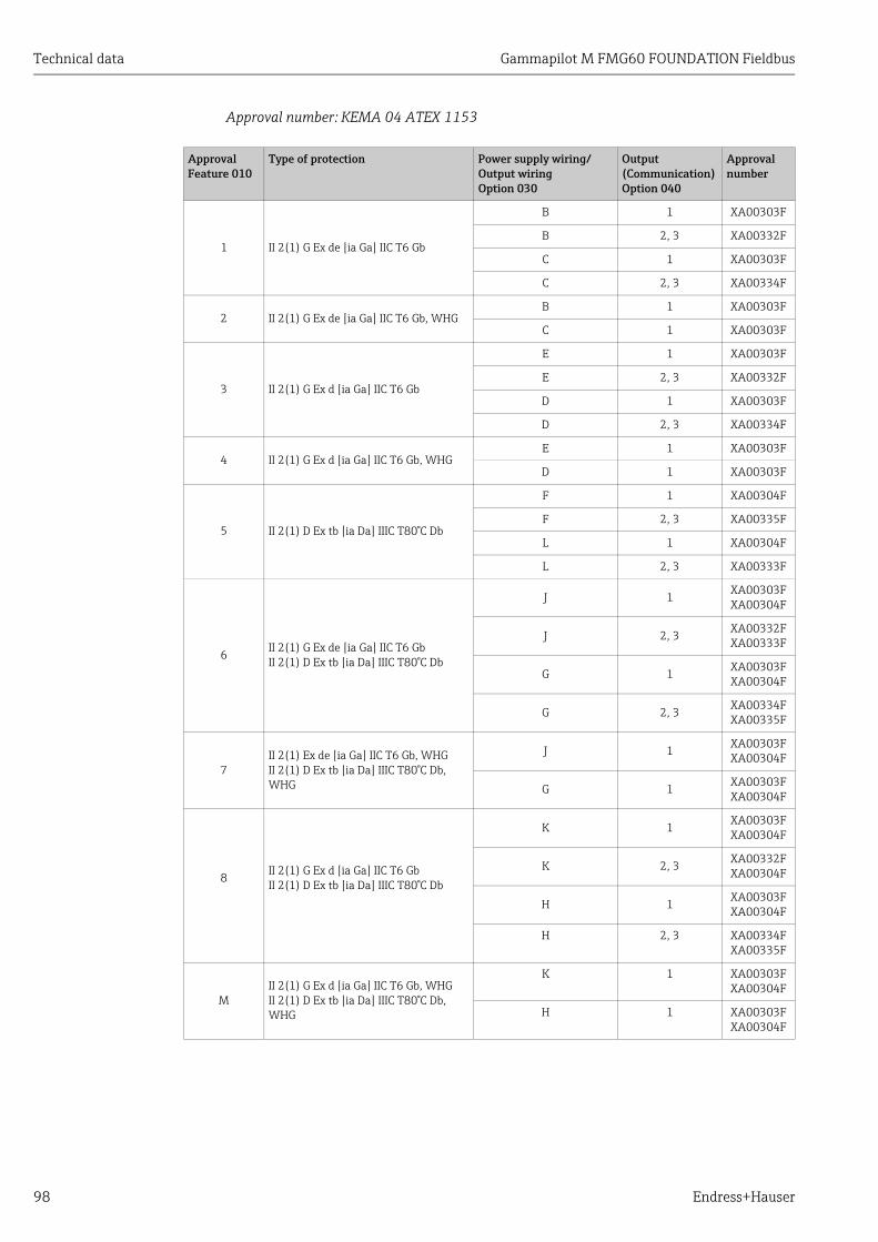
Technical data Gammapilot M FMG60 FOUNDATION Fieldbus
98 Endress+Hauser
Approval number: KEMA 04 ATEX 1153
ApprovalFeature 010
Type of protection Power supply wiring/Output wiringOption 030
Output(Communication)Option 040
Approval number
1 II 2(1) G Ex de [ia Ga] IIC T6 Gb
B 1 XA00303F
B 2, 3 XA00332F
C 1 XA00303F
C 2, 3 XA00334F
2 II 2(1) G Ex de [ia Ga] IIC T6 Gb, WHGB 1 XA00303F
C 1 XA00303F
3 II 2(1) G Ex d [ia Ga] IIC T6 Gb
E 1 XA00303F
E 2, 3 XA00332F
D 1 XA00303F
D 2, 3 XA00334F
4 II 2(1) G Ex d [ia Ga] IIC T6 Gb, WHGE 1 XA00303F
D 1 XA00303F
5 II 2(1) D Ex tb [ia Da] IIIC T80°C Db
F 1 XA00304F
F 2, 3 XA00335F
L 1 XA00304F
L 2, 3 XA00333F
6II 2(1) G Ex de [ia Ga] IIC T6 GbII 2(1) D Ex tb [ia Da] IIIC T80°C Db
J 1XA00303FXA00304F
J 2, 3 XA00332FXA00333F
G 1 XA00303FXA00304F
G 2, 3XA00334FXA00335F
7II 2(1) Ex de [ia Ga] IIC T6 Gb, WHGII 2(1) D Ex tb [ia Da] IIIC T80°C Db, WHG
J 1 XA00303FXA00304F
G 1 XA00303FXA00304F
8 II 2(1) G Ex d [ia Ga] IIC T6 GbII 2(1) D Ex tb [ia Da] IIIC T80°C Db
K 1XA00303FXA00304F
K 2, 3 XA00332FXA00304F
H 1 XA00303FXA00304F
H 2, 3 XA00334FXA00335F
MII 2(1) G Ex d [ia Ga] IIC T6 Gb, WHGII 2(1) D Ex tb [ia Da] IIIC T80°C Db, WHG
K 1 XA00303FXA00304F
H 1 XA00303FXA00304F
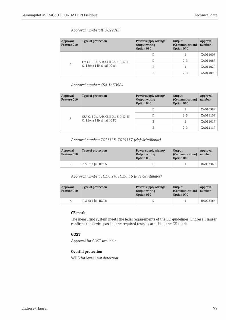
Gammapilot M FMG60 FOUNDATION Fieldbus Technical data
Endress+Hauser 99
Approval number: ID 3022785
Approval number: CSA 1653884
Approval number: TC17525, TC19557 (NaJ-Scintillator)
Approval number: TC17524, TC19556 (PVT-Scintillator)
CE mark
The measuring system meets the legal requirements of the EC-guidelines. Endress+Hauser confirms the device passing the required tests by attaching the CE-mark.
GOST
Approval for GOST available.
Overfill protection
WHG for level limit detection.
ApprovalFeature 010
Type of protection Power supply wiring/Output wiringOption 030
Output(Communication)Option 040
Approval number
S FM Cl. 1 Gp. A-D, Cl. II Gp. E-G, Cl. III, Cl. I Zone 1 Ex d [ia] IIC t6
D 1 XA01100F
D 2, 3 XA01108F
E 1 XA01102F
E 2, 3 XA01109F
ApprovalFeature 010
Type of protection Power supply wiring/Output wiringOption 030
Output(Communication)Option 040
Approval number
P CSA Cl. I Gp. A-D, Cl. II Gp. E-G, Cl. III, Cl. I Zone 1 Ex d [ia] IIC T6
D 1 XA01099F
D 2, 3 XA01110F
E 1 XA01101F
E 2, 3 XA01111F
ApprovalFeature 010
Type of protection Power supply wiring/Output wiringOption 030
Output(Communication)Option 040
Approval number
K TIIS Ex d [ia] IIC T6 D 1 BA00236F
ApprovalFeature 010
Type of protection Power supply wiring/Output wiringOption 030
Output(Communication)Option 040
Approval number
K TIIS Ex d [ia] IIC T6 D 1 BA00236F

Appendix Gammapilot M FMG60 FOUNDATION Fieldbus
100 Endress+Hauser
11 Appendix
11.1 Operating menu for level measurements
A0018681-EN
E
ESC
safety settings
basic setup
output on alarm
MAXholdMIN
todays date
dd.mm.yy hh:mm
gammagr . detect
on
off
present error
device tag
operating mode
linearisation
linearstandardclear table
language
previous error
isotope
137Cs60 Cono compens.
table no
back to home
specify timeDefault: 100 s
clear last error
keeperase
protocol + sw-no.
beam type
standard / cont.modulated
input level
reset
for reset codesee manual
Note! The Default values of the parameters are typed in bold.
no. of decimalas
xx.x
x.xxxx.xx
unlock parameter
for unlock codesee manual
DD revision
linearisation
gammagraphy
output
display
diagnostics
system parameters
L2
*0
L20
*01
L50
LA0
LC0
*04
L40
L92
LA1
*03
L41 L42
L93
LA2
LC2
*02
LA3
L95
LA4
LC4
L4
L5
L6
L9
LA
LC
define tabletable on
span time
minimal time frommin. to max. value
sensitivityL51 L52 output gammagr . L53
slaveend slavenot defined
calibration L1 backgr . calib. L10
start
stop/edit
avg. pulse rate L11 bgr . pulse rate
-1: not calibrated
L12 calibr . point
full/covered
L13
empty/free
value full L14
target value atcalibration point
hold time L54
masterstand alone meas. mode
level(see separate menusfor other selections)
*05
value empty L17
target value atcalibration point
MINMAXhold
* in preparation
device id dev . rev .LC1 LC3

Gammapilot M FMG60 FOUNDATION Fieldbus Appendix
Endress+Hauser 101
A0018683-EN
E
E
E
simulation
sim. off
sim pulseratesim. level
sep. character
. period, comma
pres. avg. pulsr .
temperature unit
simulation value
display test
offon
avg. raw pulsr .
calibration date
Ret
urn
to G
rou
p s
elec
tion
output damping
L65
L96
LA5
LC6
L66
L97
LA6
LC7
L0B
calibration L15
start
stop/edit
avg. pulse rate L11 full calibr .
-1: not calibrated
L16
calibration L15
start
stop/edit
avg. pulse rate L11 empty calibr .
-1: not calibrated
L18
next point L19
yes
no
calibration L43
start
stop/edit
avg. pulse rate L11 normalized pulser .
-1: not calibrated
L44 next point L4B
yes
no
gammagr . count L56
keeperase
gammagr . count L55
°C°F
dd.mm.yy hh:mm
1 … 999 sDefault: 6 s
decay compensatedw/o background rate
at integration timenot compensated

Appendix Gammapilot M FMG60 FOUNDATION Fieldbus
102 Endress+Hauser
11.2 Operating menu for level limit detection
A0018684-EN
E
basic setup todays date
dd.mm.yy hh:mm
gammagr . detect
on
off
present error
device tag
operating mode
language
previous error
isotope
137Cs60 Cono compens.
back to home
specify timeDefault: 100 s
clear last error
keeperase
protocol + sw-no.
beam type
standard / cont.modulated
reset
for reset codesee manual
Note! The Default values of the parameters are typed in bold.
no. of decimalas
xx.x
x.xxxx.xx
unlock parameter
for unlock codesee manual
DD revision
gammagraphy
display
diagnostics
system parameters
*0 *01
S50
SA0
SC0
*04
S92
SA1
*03
S93
SA2
SC2
*02
SA3
S95
SA4
SC4
S5
S9
SA
SC
span time
minimal time frommin. to max. value
sensitivityS51 S52 output gammagr . S53
slaveend slavenot defined
calibration S1 backgr . calib. S10
start
stop/edit
avg. pulse rate S1 1 bgr . pulse rate
-1: not calibrated
S12 calibr . point
full/covered
S13
empty/free
hold time S54
masterstand alone meas. mode
limit(see separate menusfor other selections)
*05
MINMAXhold
* in preparation
output S6
device id SC1 device revision SC3
safety settings output on alarm
MAX 110%holdMIN - 10%
user specific output on alarm
specify value
S2 S20
S21

Gammapilot M FMG60 FOUNDATION Fieldbus Appendix
Endress+Hauser 103
A0018685-EN
E
E
simulation
sim. off
sim. pulseratesim. level
sep. character
. period, comma
pres. avg. pulsr .
temperatiure unit
simulation value
display test
offon
avg. raw pulsr .
calibration date
Ret
urn
to G
rou
p s
elec
tion
output damping
S65
S96
SA5
SC6
S66
S97
SA6
SC7
S0B
calibration S15
start
stop/edit
avg. pulse rate S1 1 full calibr .
-1: not calibrated
S16
calibration S15
start
stop/edit
avg. pulse rate S1 1 empty calibr .
-1: not calibrated
S18
next point S19
yes
no
gammagr . count S56
keeperase
gammagr . count S55
°C°F
dd.mm.yy hh:mm
1 … 999 sDefault: 6 s
decay compensatedw/o background rate
at integration timenot compensated

Appendix Gammapilot M FMG60 FOUNDATION Fieldbus
104 Endress+Hauser
11.3 Operating menu for density and concentration measurements
A0018687-EN
*
E E
ESC
ESC
*53
safety settings
basic setup
output on alarm
MAXholdMIN
todays date
dd.mm.yy hh:mm
gammagr . detect
on
off
present error
device tag
operating mode
linearisation
clear table
language
previous error
isotope
137Cs60 Cono compens.
table no
back to home
specify timeDefault: 100 s
clear last error
keeperase
protocol + sw-no.
beam type
standard / cont.modulated
input density
reset
for reset codesee manual
Note! The Default values of the parameters are typed in bold.
no. of decimalas
xx.x
x.xxxx.xx
unlock parameter
for unlock codesee manual
DD revision
linearisation
gammagraphy
output
display
diagnostics
system parameters
*2
*0
*20
*01
*50
*A0
*C0
*04
*47
*92
*A1
*03
*48 *49
*93
*A2
*C2
*02
*A3
*05
*95
*A4
*C4
*4
*5
*6
*9
*A
*C
edit tabletable on
span time
minimal time frommin. to max. value
sensitivity*51 *52 output gammagr . *53
slaveend slavenot defined
calibration *1 backgr . calib. *10
start
stop/edit
avg. pulse rate *11 bgr . pulse rate
-1: not calibrated
*12 calibr . point
1 … 10
*1A calibration *15
start
stop/edit
avg. pulse rate *11
hold time *54
masterstand alone
temp. compens. select temper . temperature density linear coef f.temp. compensation *30 *31 *32 *33 *34*3
referencelowesthighest
clear
unit selection *45 customer unit *46
g/cm3g/llb/gallb/ft3
°Brix°Baume°API°Twad
meas. mode
density/concentration(see separate menusfor other selections)
not usedused
customer unit %% mass%vol
sol/volg dm/l
density unit
MINMAXhold
* in preparation
device id *A1 device revision *A3

Gammapilot M FMG60 FOUNDATION Fieldbus Appendix
Endress+Hauser 105
A0018688-EN
*
simulation
sim. off
sim. pulserate.sim. density/concentr .
sep. character
. period, comma
pres. avg. pulsr .
temperatiure unit
simulation value
display test
offon
avg. raw pulsr .
calibration date
Ret
urn
to G
rou
p s
elec
tion
pipe diam. unit
*65
*96
*A5
*C6
*66
*97
*A6
*C7
*09
density calibr .
-1: not calibrated
*1B *19
input concentr . *4A next point *4B
yes
no
gammagr . count *56
keeperase
gammagr . count *55
°C°F
dd.mm.yy hh:mm
density unit *06
g/cm3g/l…
min. density *07
density value *1C *1D *1E *1F
square coef f. next point*35 *36
yes
no
max. density *08
medium temp. *A7 density value *A8
recalibration date *C8
dd.mm.yy hh:mm
pipe diam. *0A outp. damp. *0B
1 … 999 sDefault: 60 s
decay compensatedw/o background rate
at integration timenot compensated
without temp.compensation
next point
yes
no
calibr . point
not usedusedclear
absorp. coef f ref. pulse rate

Gammapilot M FMG60 FOUNDATION Fieldbus
106 Endress+Hauser
Index
Symbols*01 - Present date . . . . . . . . . . . . . . . . . . . . . . . . . . . . . . . 60*03 - Isotope . . . . . . . . . . . . . . . . . . . . . . . . . . . . . . . . . . . 60*04 - Operating mode. . . . . . . . . . . . . . . . . . . . . . . . . . . . 61*05 - Measuring mode . . . . . . . . . . . . . . . . . . . . . . . . . . . 62*06 - Density unit . . . . . . . . . . . . . . . . . . . . . . . . . . . . . . . 63*07 - Min. density . . . . . . . . . . . . . . . . . . . . . . . . . . . . . . . 63*08 - Max. density . . . . . . . . . . . . . . . . . . . . . . . . . . . . . . 63*09 - Pipe diameter unit. . . . . . . . . . . . . . . . . . . . . . . . . . 63*0A - Pipe diameter . . . . . . . . . . . . . . . . . . . . . . . . . . . . . 64*0B - Output damping . . . . . . . . . . . . . . . . . . . . . . . . . . . 65*10 - Background calibration. . . . . . . . . . . . . . . . . . . 69, 77*11 - Average pulse rate (background) . . . . . . . . . . 70, 78*11 - Average pulse rate (density) . . . . . . . . . . . . . . . . . 80*11 - Average pulse rate (level/limit) . . . . . . . . . . . . . . 73*12 - Background pulse rate . . . . . . . . . . . . . . . . . . . 70, 78*13 - Calibration point (level/limit) . . . . . . . . . . . . . . . . 71*14 - Value full . . . . . . . . . . . . . . . . . . . . . . . . . . . . . . . . . 72*15 - Calibration . . . . . . . . . . . . . . . . . . . . . . . . . . . . . . . . 72*15 - Calibration (density) . . . . . . . . . . . . . . . . . . . . . . . . 80*16 - Full calibration. . . . . . . . . . . . . . . . . . . . . . . . . . . . . 73*17 - Value empty. . . . . . . . . . . . . . . . . . . . . . . . . . . . . . . 72*18 - Empty calibration . . . . . . . . . . . . . . . . . . . . . . . . . . 73*19 - Next point (density) . . . . . . . . . . . . . . . . . . . . . . . . 82*19 - Next point (level/limit). . . . . . . . . . . . . . . . . . . . . . 74*1A - Calibration point . . . . . . . . . . . . . . . . . . . . . . . . . . . 79*1B - Density calibration . . . . . . . . . . . . . . . . . . . . . . . . . 81*1C - Density value . . . . . . . . . . . . . . . . . . . . . . . . . . . . . . 81*1D - Calibration point . . . . . . . . . . . . . . . . . . . . . . . . . . . 81*1E - Absorption coefficient . . . . . . . . . . . . . . . . . . . . . . 82*1F - Reference pulse rate . . . . . . . . . . . . . . . . . . . . . . . . 82
AAlarm . . . . . . . . . . . . . . . . . . . . . . . . . . . . . . . . . . . . . . . . . 92Automatic calibration . . . . . . . . . . . . . . . . . . . . . . . . . 68, 76
BBackground calibration. . . . . . . . . . . . . . . . . . . . . . . . 66–67Basic setup . . . . . . . . . . . . . . . . . . . . . . . . . . . . . . . . . . . . . 60
CCable entries. . . . . . . . . . . . . . . . . . . . . . . . . . . . . . . . . . . . 20Calibration errors. . . . . . . . . . . . . . . . . . . . . . . . . . . . . . . . 95Calibration points . . . . . . . . . . . . . . . . . . . . . . . . 66–67, 75Cascading mode . . . . . . . . . . . . . . . . . . . . . . . . . . . . . . . . . 28CE mark. . . . . . . . . . . . . . . . . . . . . . . . . . . . . . . . . . . . . . . . 10Centering knob. . . . . . . . . . . . . . . . . . . . . . . . . . . . . . . . . . . . 8Clamping device for density measurements. . . . . . . 91, 96Concentration measurement . . . . . . . . . . . . 15–16, 75, 83Cooling water connections . . . . . . . . . . . . . . . . . . . . . . . . . . 8Covered calibration . . . . . . . . . . . . . . . . . . . . . . . . . . . . . . 67
DDeclaration of conformity. . . . . . . . . . . . . . . . . . . . . . . . . 10Density measurement . . . . . . . . . . . . . . . . . . 15–16, 75, 83Detector pipe . . . . . . . . . . . . . . . . . . . . . . . . . . . . . . . . . . . . . 8Dimensions. . . . . . . . . . . . . . . . . . . . . . . . . . . . . . . . . . . . . 12
Display operation . . . . . . . . . . . . . . . . . . . . . . . . . . . . 31, 34Display symbols . . . . . . . . . . . . . . . . . . . . . . . . . . . . . . . . . . 31Disposal . . . . . . . . . . . . . . . . . . . . . . . . . . . . . . . . . . . . . . . . 85Documentation . . . . . . . . . . . . . . . . . . . . . . . . . . . . . . . . . . 10
EEinpunkt-Abgleich . . . . . . . . . . . . . . . . . . . . . . . . . . . . . . . 75Empty calibration . . . . . . . . . . . . . . . . . . . . . . . . . . . . . . . . 67Error codes . . . . . . . . . . . . . . . . . . . . . . . . . . . . . . . . . . . . . . 93Error messages . . . . . . . . . . . . . . . . . . . . . . . . . . . . . . . . . . 92Exterior cleaning . . . . . . . . . . . . . . . . . . . . . . . . . . . . . . . . . 84
FFHX40. . . . . . . . . . . . . . . . . . . . . . . . . . . . . . . . . . . . . . 27, 87Fieldbus connector . . . . . . . . . . . . . . . . . . . . . . . . . . . . . . . 23Free calibration . . . . . . . . . . . . . . . . . . . . . . . . . . . . . . . . . . 67Full calibration. . . . . . . . . . . . . . . . . . . . . . . . . . . . . . . . . . . 66Function code . . . . . . . . . . . . . . . . . . . . . . . . . . . . . . . . . . . 33
HHardware security locking . . . . . . . . . . . . . . . . . . . . . . . . . 36Hazardous area . . . . . . . . . . . . . . . . . . . . . . . . . . . . . . . . . . . 4
IIncoming acceptance. . . . . . . . . . . . . . . . . . . . . . . . . . . . . . 11Installation conditions . . . . . . . . . . . . . . . . . . . . . . . . . . . . 12
KKey assignment . . . . . . . . . . . . . . . . . . . . . . . . . . . . . . . . . . 32Klemmvorrichtung für Dichtemessung . . . . . . . . . . . . . . 96
LLevel limit detection . . . . . . . . . . . . . . . . . . . . . . . . . . 14, 66Level measurement. . . . . . . . . . . . . . . . . . . . . . . . . . . 13, 66Linearization . . . . . . . . . . . . . . . . . . . . . . . . . . . . . . . . . . . . 83
MManual calibration . . . . . . . . . . . . . . . . . . . . . . . . . . . 68, 76Measurement section . . . . . . . . . . . . . . . . . . . . . . . . . 91, 96Measuring range marks . . . . . . . . . . . . . . . . . . . . . . . . . . . . 8Menu. . . . . . . . . . . . . . . . . . . . . . . . . . . . . . . . . . . . . . 33, 100Mounting collar . . . . . . . . . . . . . . . . . . . . . . . . . . . . . . . . . . . 8mounting device FHG60. . . . . . . . . . . . . . . . . . . . . . . . . . . 89Multiple-point calibration . . . . . . . . . . . . . . . . . . . . . . . . . 76
NNameplates . . . . . . . . . . . . . . . . . . . . . . . . . . . . . . . . . . . 8–9
OOne-point calibration . . . . . . . . . . . . . . . . . . . . . . . . . . . . . 75Onsite display . . . . . . . . . . . . . . . . . . . . . . . . . . . . . . . . . . . 34Operating options . . . . . . . . . . . . . . . . . . . . . . . . . . . . . . . . 30
PPML connector . . . . . . . . . . . . . . . . . . . . . . . . . . . . . . . . . . . 8Potential equalization. . . . . . . . . . . . . . . . . . . . . . . . . . . . . 24

Gammapilot M FMG60 FOUNDATION Fieldbus
Endress+Hauser 107
RRadiation protection . . . . . . . . . . . . . . . . . . . . . . . . . . . . . . . 5Recalibration . . . . . . . . . . . . . . . . . . . . . . . . . . . . . . . . . . . 76Repair . . . . . . . . . . . . . . . . . . . . . . . . . . . . . . . . . . . . . . . . . 84Replacement. . . . . . . . . . . . . . . . . . . . . . . . . . . . . . . . . . . . 84Reset . . . . . . . . . . . . . . . . . . . . . . . . . . . . . . . . . . . . . . . . . . 36Return . . . . . . . . . . . . . . . . . . . . . . . . . . . . . . . . . . . . . . . . . 85
SSafety instructions. . . . . . . . . . . . . . . . . . . . . . . . . . . . . . . . . 4Scope of delivery . . . . . . . . . . . . . . . . . . . . . . . . . . . . . . . . . . 9Security locking . . . . . . . . . . . . . . . . . . . . . . . . . . . . . . . . . 36Service interface FXA291 . . . . . . . . . . . . . . . . . . . . . . . . . 86Software history. . . . . . . . . . . . . . . . . . . . . . . . . . . . . . . . . 95Software security locking . . . . . . . . . . . . . . . . . . . . . . . . . 36Storage . . . . . . . . . . . . . . . . . . . . . . . . . . . . . . . . . . . . . . . . 11
TTerminal assignment . . . . . . . . . . . . . . . . . . . . . . . . . . . . 21Terminal compartments . . . . . . . . . . . . . . . . . . . . . . . . 8, 20Terminal head . . . . . . . . . . . . . . . . . . . . . . . . . . . . . . . . . . . . 8ToF Tool - FieldTool Package . . . . . . . . . . . . . . . . . . . . . . 35Trademarks . . . . . . . . . . . . . . . . . . . . . . . . . . . . . . . . . . . . 10Transport . . . . . . . . . . . . . . . . . . . . . . . . . . . . . . . . . . . . . . 11Types of error . . . . . . . . . . . . . . . . . . . . . . . . . . . . . . . . . . . 92
UUnlock parameter . . . . . . . . . . . . . . . . . . . . . . . . . . . . . . . 36
VVU331. . . . . . . . . . . . . . . . . . . . . . . . . . . . . . . . . . . . . . . . . 31
WWarning . . . . . . . . . . . . . . . . . . . . . . . . . . . . . . . . . . . . . . . 92Water cooling. . . . . . . . . . . . . . . . . . . . . . . . . . . . . . . . . . . 17Weight . . . . . . . . . . . . . . . . . . . . . . . . . . . . . . . . . . . . . . . . 12Wiring . . . . . . . . . . . . . . . . . . . . . . . . . . . . . . . . . . . . . . . . . 20

www.addresses.endress.com
71298585


