Operating Manual DC-1, DC-2, DC-3, DC-4 Page 1 PACKAGING When ordered as a complete apparatus four cartons will be received: a) water jacket and glass columns (DC-1 or DC-4) b) TE-10A thermoregulator unit c) filling device and all accessories (DC-2) d) column clearing device (DC-3) Remove the packing list and verify that all equipment has been received. If there are any questions about the shipment, please call TECHNE Customer Service Department at 1/800/225- 9243 or 609/589-2560. Inspect all shipping containers for signs of damage which may have been caused by rough handling in transit. If damage exists, immediately contact shipping agent. Very carefully remove all the component parts from the packing boxes, taking particular care when handling the glass column and capillary tube. Wipe all parts clean with a soft damp cloth. Retain the carton in which the bath is received until the unit is tested and found to be in good condition. ELECTRICAL Check the voltage and current rating on the serial number plates of the TE-10A Tempette and DC-2 Magnetic Stirring Platform are correct. WARRANTY Components used in this apparatus are guaranteed against all defects, including materials and workmanship, under normal use for a period of twelve months. To validate the warranty, complete and return the warranty card immediately. INTRODUCTION DC-1 is a single column and DC-4 is a double column. This manual includes operating instructions for both the single and double columns, as well as the DC-2 Filling Device (with Accessories) and the DC-3 Clearing Device.
Transcript
Operating Manual DC-1, DC-2, DC-3, DC-4
Page 1
PACKAGING When ordered as a complete apparatus four cartons will be received: a) water jacket and glass columns (DC-1 or DC-4) b) TE-10A thermoregulator unit c) filling device and all accessories (DC-2) d) column clearing device (DC-3) Remove the packing list and verify that all equipment has been received. If there are any questions about the shipment, please call TECHNE Customer Service Department at 1/800/225-9243 or 609/589-2560. Inspect all shipping containers for signs of damage which may have been caused by rough handling in transit. If damage exists, immediately contact shipping agent. Very carefully remove all the component parts from the packing boxes, taking particular care when handling the glass column and capillary tube. Wipe all parts clean with a soft damp cloth. Retain the carton in which the bath is received until the unit is tested and found to be in good condition. ELECTRICAL Check the voltage and current rating on the serial number plates of the TE-10A Tempette and DC-2 Magnetic Stirring Platform are correct. WARRANTY Components used in this apparatus are guaranteed against all defects, including materials and workmanship, under normal use for a period of twelve months. To validate the warranty, complete and return the warranty card immediately. INTRODUCTION DC-1 is a single column and DC-4 is a double column. This manual includes operating instructions for both the single and double columns, as well as the DC-2 Filling Device (with Accessories) and the DC-3 Clearing Device.
Operating Manual DC-1, DC-2, DC-3, DC-4
Page 2
Principal of Operation for the DC-1/DC-4 Density Column The density gradient technique is dependent upon the hydrostatic equilibrium between a solid specimen and a liquid of identical density. A column of liquid having an approximate linear density gradient is maintained at a constant temperature. Calibrated density standards, in the form of glass floats are introduced into the column and a graph of position against which density can be plotted. A specimen placed into the density column will descend until it reaches the level where the density of the liquid is equal to that of the specimen. From the measurement of height, the specimen density can be read off the graph. Principle of Operation of the DC-2 Filling Device The DC-2 Filling Device provides the equipment necessary for producing the linear density gradient. It consists of a platform which includes a built-in magnetic stirrer; a glass enclosed stirrer bar to ensure homogeneity of mixture before introducing into the column tube; and two flasks for holding the two column liquids prior to mixing. All necessary interconnecting taps and clips are provided. Principle of Operation of the DC-3 Clearing Device The clearing device consists of a conical plastic basket suspended by a nylon thread attached to a small reversible motor, which is mounted on the top of the plexiglass water jacket by two clamp screws. This basket is weighted to make it move axially within the graduated column tube. A layer of polyethylene webbing around the basket ensures that all specimens and floats within the column tube are collected as the basket is raised. This apparatus (DC-1 or DC-2 with TE-10A and optional accessories) meets the temperature and dimensional requirements of BS 3715 and ASTM D1505-60T. Accurately calibrated glass floats are supplied to individual specifications. It is recommended that floats are ordered in sets of eight to cover the density range of interest, although individual floats specified to a particular density no closer than two decimal points, can be supplied. All floats are approximately 6.4mm (0.25 in.) diameter and calibrated to four decimal places with an accuracy of +/-0.0002 g/ml at 23° C (73° F). Floats are available in the range of 0.8 g/ml to 1.7 g/ml.
Operating Manual DC-1, DC-2, DC-3, DC-4
Page 3
INSTALLATION/OPERATING PROCEDURE: DC-1/DC-4 AND TE-10A Remove all components from the cartons in which they were received. Confirm that the voltage listed on the rating plate of the TE-10A is appropriate. Refer to the TE-10A instruction manual as required. Connect and clear plastic tubing inside the plexiglass vessel to the removable outlet nozzle on the TE-10A. The black neoprene sleeve which fits over the plastic tubing may be trimmed if necessary when mounting on the outlet nozzle. Use needle-nosed pliers, if needed, to fit the nozzle with attached tubing to the outlet side (right-hand side) of the TE-10A's pump. Apply RTV compound around the inserted nozzle to insure a good seal. Refer to the TE-10A Operating Manual for detailed description of this unit. Mount the Tempette into the rectangular hole in the top plate of the water jacket, and lightly turn the clamping screw until it makes contact with the outside wall of the plexiglass water jacket.
DO NOT OVER TIGHTEN!!
Move the apparatus to the location where use is intended. Fill the plexiglass water jacket housing to within one inch from the top with distilled water (through the column aperture). A de-mineralized water with about 2% Ethylene Glycol (anti-freeze) is a useful alternative, as it reduces deposits and algae growth within the jacket. Once filled with water, the jacket should be moved as little as possible. When movement is necessary, care should be given to support the base of the apparatus. Insert a thermometer into the vessel through the small hole provided in the top; set the Tempette dial to approximately 23° C. Refer to the TE-10A Operating Manual for details. Allow the water to heat up. As the required temperature is approached, adjust the temperature dial on top of the Tempette until the neon indicator switches off at the exact temperature. Check the temperature after the unit has been controlling the apparatus for a short time (the temperature should be 23° C +/-0.1° C). If the ambient temperature is higher than 19° C, then cold water should be circulated through the cooling coil in order that the Tempette can operate efficiently. Insert the column tube in the water vessel. To overcome the buoyancy, clip the column tube down by stretching the rubber band over the metal tags under the top cover fixing screws. The column is now ready for the filling operation.
Operating Manual DC-1, DC-2, DC-3, DC-4
Page 4
COLUMN FILLING PROCEDURE When selecting the two liquids (a and b) the following are important considerations: • Both liquids should be readily available and they must obviously be miscible. • Choose preferably colorless, low viscosity liquids. • The liquids must span the required density gradient, and should easily wet the samples. • The liquids must not have an adverse effect on the samples to be tested. • The top two liquids can themselves be prepared solutions prior to mixing in the filling
device. With the above considerations in mind, prepare the two solutions; 'a' having a density 20% (of the whole range) below the lowest density required, and 'b', having a density 30% (of the whole range) above the highest density required (ref. BS 3715). After the outlet taps have been closed, one liter of each solution is required and should be placed in individual conical flasks. Note that if the densities of the two liquids differ by 5% or more, it is necessary to add a greater volume of solution of the lower density ('a') in the flask. The heights of the surfaces of the two solutions above the filling device platform should be proportional to their density. This will insure that when the connecting tap between the two flasks is opened, an approximate equilibrium condition will exist. It is important that the total volume of the two solutions be two liters. Note: The wider the column range required, the more difficult it becomes to obtain linearity for ranges not exceeding approximately 0.3 g/cc. With ranges exceeding this value, it may be necessary to either: Use an auxiliary stirrer through the top of the flask with the magnetic stirrer. In this instance, care must be taken not to introduce air bubbles into the liquid.
OR
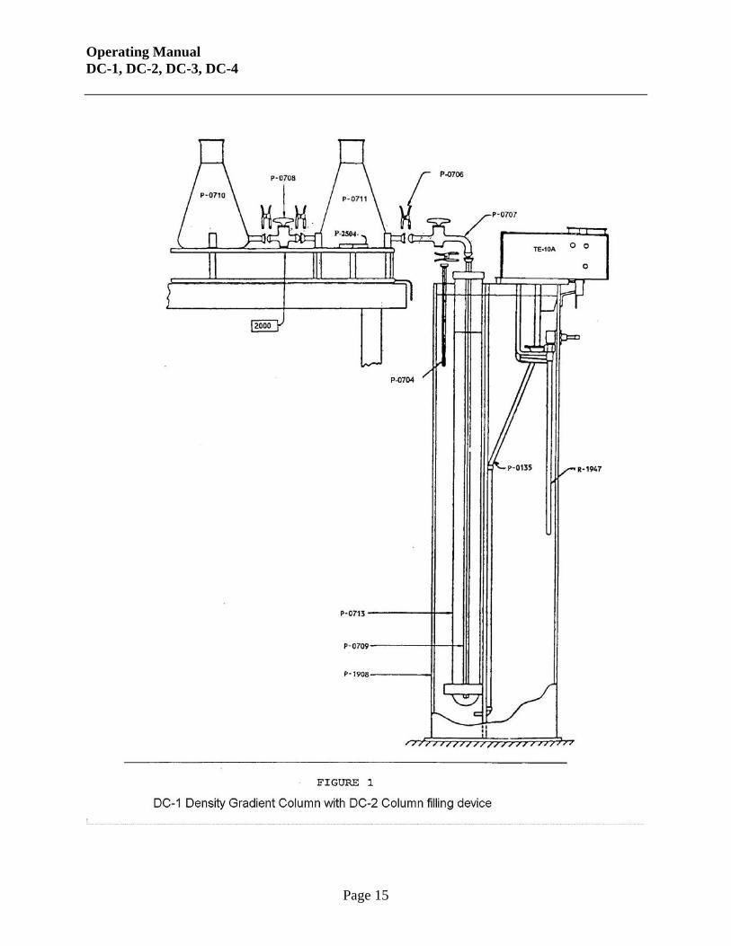
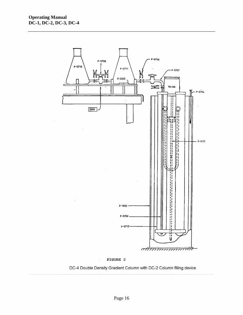
By considerably increasing the total filling time up to, say, four hours. If necessary, the solutions may be de-gassed by evacuation at a pump pressure of approximately 60 cm. A water filter pump is suitable. Insert the capillary filling tube (part number 7000135) down into the graduated column tube until the lower end rests on the bottom. Link up the rest of the apparatus as shown in Figure 3; the stirrer and the flasks can stand on a bench next to the column.
Operating Manual DC-1, DC-2, DC-3, DC-4
Page 5
Connect the magnetic stirrer to the appropriate electrical supply and switch on. Fully open the connecting tap between the two vessels. Allow time for hydrostatic equilibrium to be established between the two vessels and then open the outlet tap to the capillary tube. The column will then slowly fill, this process should take approximately 2 hours. Regulation of the filling rate is possible by adjusting the outlet tap, do not, however, make an adjustment once a filling operation has started. During the filling operation, the density of solution 'a' will increase continuously as the solution of the higher density in flask 'b' flows into it and will introduce a solution of continuously graded density into the column. When the column tube is sufficiently filled above the scale's top mark, shut off the outlet tap, switch off the magnetic stirring platform, and very slowly and carefully remove the capillary filling tube. Retain some of the denser solution for subsequent specimen wetting. Position the apparatus where it is to be used. Select eight very clean and calibrated glass density floats to cover the density range of the column. Starting with the highest value float, wet each one with some of the left over solution and place them into the column. Before actually releasing the floats, make sure there are no visible air bubbles attached. The floats will then assume their own density level in the column. Note: Since a large number of samples may eventually be placed into the column, some form of identification is necessary. This is best achieved by identifying the shape of the specimens in simple geometric forms. It is important that their center of volume be easily known, therefore, by combining geometric shapes, a large number of different specimens are easily identifiable. Always use a sharp cutting tool to avoid straining the material. After the specimens have reached equilibrium, their positions (centers of volumes) can be determined by means of the anti-parallax scale on the column tube. Density of the specimen can then be read directly from the graph. When attempting to assess density to +/- 0.0002 g/cc, the specimens should always be double checked, even by immersion in a second column. The graph should be replotted each time the column is used. If practical, it is advisable to allow at least twelve hours before taking readings of specimen density.
After removing the DC-3 from its shipping carton, check the rating plate to confirm that the voltage is appropriate. The DC-3 Clearing Device is mounted above the graduated tube, onto the plexiglass top of the water jacket. Two thumb screws are used to connect the DC-3 to the density column. When the column has been set up, the calibrated glass density floats are placed in the basket. The motor is switched to the "DOWN" position. As each float reaches its own density in the column, it remains at the level while the basket continues to descend. In order not to disturb the gradient, the basket will take approximately 40 minutes to travel the whole length of the tube. When the basket has reached the bottom of the tube, the motor has to be switched manually to the "OFF" position. Failure to switch the motor off may cause the basket to pivot, spilling the floats/specimens. CAUTION: When the column clearing device is used, we recommend that it's operation be monitored. POSSIBLE SOURCES OF ERROR If the readings obtained from several specimens of the same sample differ widely, then more specimens should be tested to see if the spread of results is real. However, errors can be due to: • The specimens may have voids within or have air bubbles attached. In such a case, the
higher density value should be accepted, especially if it is the most frequent occurrence. • There is foreign matter embedded in the specimens. In this case, cut the specimen into two
or more pieces and determine the density of these by placing them in the column. • The column may become so choked with specimens that interference between them may
prevent precise readings. It is possible to clear the column of all specimens and floats by means of a wire mesh basket which is drawn very slowly up through the column. Float/specimen removal, as described, can be accomplished with the DC-3 Clearing Device.
Operating Manual DC-1, DC-2, DC-3, DC-4
Page 7
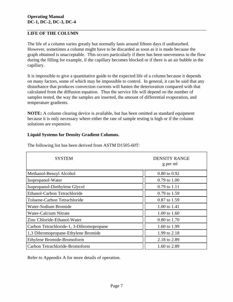
LIFE OF THE COLUMN The life of a column varies greatly but normally lasts around fifteen days if undisturbed. However, sometimes a column might have to be discarded as soon as it is made because the graph obtained is unacceptable. This occurs particularly if there has been unevenness in the flow during the filling for example, if the capillary becomes blocked or if there is an air bubble in the capillary. It is impossible to give a quantitative guide to the expected life of a column because it depends on many factors, some of which may be impossible to control. In general, it can be said that any disturbance that produces convection currents will hasten the deterioration compared with that calculated from the diffusion equation. Thus the service life will depend on the number of samples tested, the way the samples are inserted, the amount of differential evaporation, and temperature gradients. NOTE: A column clearing device is available, but has been omitted as standard equipment because it is only necessary where either the rate of sample testing is high or if the column solutions are expensive. Liquid Systems for Density Gradient Columns. The following list has been derived from ASTM D1505-60T:
SYSTEM DENSITY RANGE g per ml
Methanol-Benzyl Alcohol 0.80 to 0.92 Isopropanol-Water 0.79 to 1.00 Isopropanol-Diethylene Glycol 0.79 to 1.11 Ethanol-Carbon Tetrachloride 0.79 to 1.59 Toluene-Carbon Tetrachloride 0.87 to 1.59 Water-Sodium Bromide 1.00 to 1.41 Water-Calcium Nitrate 1.00 to 1.60 Zinc Chloride-Ethanol-Water 0.80 to 1.70 Carbon Tetrachloride-1, 3-Dibromopropane 1.60 to 1.99 1,3 Dibromopropane-Ethylene Bromide 1.99 to 2.18 Ethylene Bromide-Bromoform 2.18 to 2.89 Carbon Tetrachloride-Bromoform 1.60 to 2.89 Refer to Appendix A for more details of operation.
Operating Manual DC-1, DC-2, DC-3, DC-4
Page 8
APPENDIX A
THEORY AND OPERATION OF A DENSITY GRADIENT COLUMN
PRINCIPLE OF COLUMN OPERATION A column of liquid having a linear gradient in density is maintained at a constant temperature to prevent temperature dependent density changes, and to prevent the formation of convection currents which would destroy the gradient. The density range of the column is selected to cover the anticipated density range of the specimens. After the gradient is established, glass floats of precisely known density are released into the column. These floats will descend to a level, measured at the center of mass, where the density of the float is the same as that of the adjacent fluid in the column. The depth of each float is determined from the scale engraved on the column, and a calibration curve of density vs. column depth plotted. (Figure 3) Specimens are wet with the lower density solution and carefully introduced into the top of the column. After they have settled to their equilibration position, their depth is read from the column scale, and their density determined from the calibration curve. PRINCIPLE BEHIND ESTABLISHING THE GRADIENT A dense (D) and less dense (L) solution are connected, and are in hydrostatic equilibrium. A capillary extends from the less dense solution to the base of column (COL) (see Fig. 2). As solution leaves the flask containing L, and is deposited in the bottom of the column, an equal mass of solution D is drawn into L, and immediately mixed with a magnetic stirrer. Solution L is now more dense than before. Some of this denser L is transported to the bottom of the column, where it layers under the less dense material already in the column. This process continues until the column has been filled to the desired level, at which time the valve from solution L to the capillary is closed and the capillary tube removed from the column. SELECTING SOLUTIONS First determine an anticipated density range for the specimens, then select (or prepare) solutions D (dense) and L (less dense) so that L has a density of approximately 20 to 25% of the range below and D has a density 30 to 35% of the range above the density range desired. For example, if the desired density range of the column is 1.60 to 1.90, the range is 0.30, so solution L might have a density of 1.54 (20% of 0.3 = 0.06 less than 1.60) and solution D might have a density of 1.99 (30% of 0.3 = 0.09 above 1.90). The solutions selected must meet several criteria before they can be used.
Operating Manual DC-1, DC-2, DC-3, DC-4
Page 9
a) They must obviously span the density range of interest. b) They must be completely miscible. c) They must be capable of wetting the specimens. d) They must not react with, or degrade, the specimens. Additional desirable properties of the liquids are: e) low viscosity f) little or no color g) readily available h) relatively non-toxic
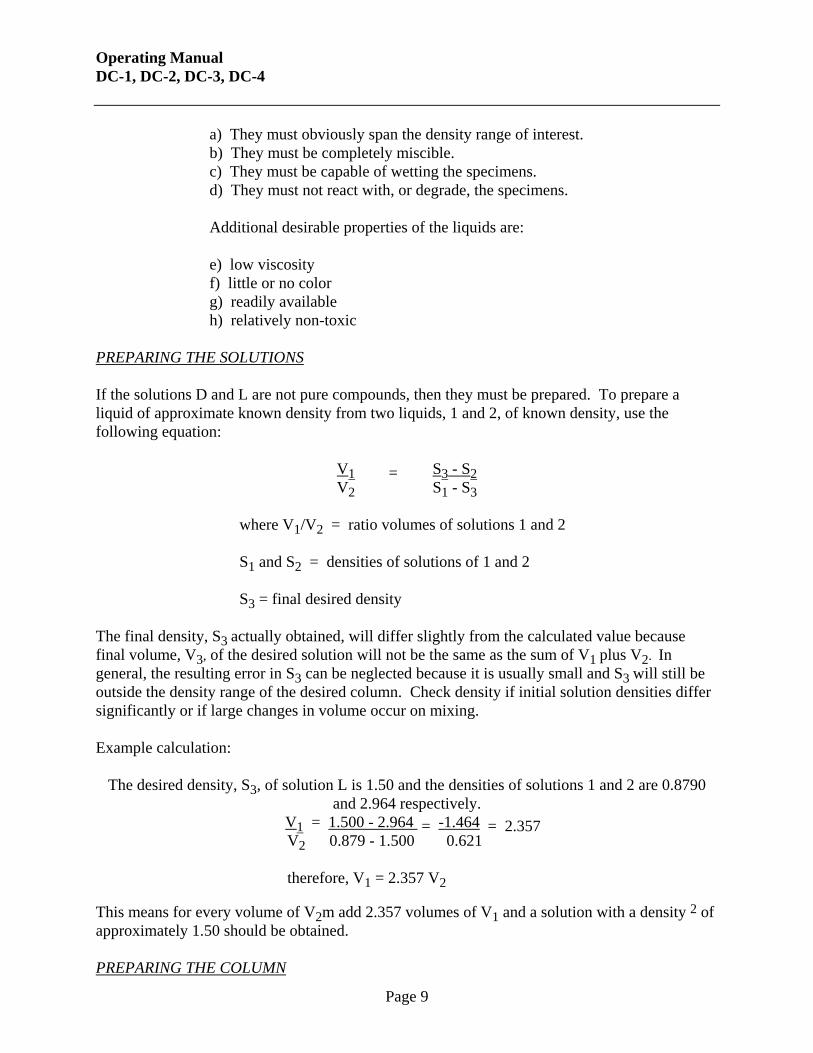
PREPARING THE SOLUTIONS If the solutions D and L are not pure compounds, then they must be prepared. To prepare a liquid of approximate known density from two liquids, 1 and 2, of known density, use the following equation:
V1 = S3 - S2 V2 S1 - S3
where V1/V2 = ratio volumes of solutions 1 and 2 S1 and S2 = densities of solutions of 1 and 2 S3 = final desired density The final density, S3 actually obtained, will differ slightly from the calculated value because final volume, V3, of the desired solution will not be the same as the sum of V1 plus V2. In general, the resulting error in S3 can be neglected because it is usually small and S3 will still be outside the density range of the desired column. Check density if initial solution densities differ significantly or if large changes in volume occur on mixing. Example calculation:
The desired density, S3, of solution L is 1.50 and the densities of solutions 1 and 2 are 0.8790
V2 0.879 - 1.500 0.621 therefore, V1 = 2.357 V2 This means for every volume of V2m add 2.357 volumes of V1 and a solution with a density 2 of approximately 1.50 should be obtained. PREPARING THE COLUMN
Operating Manual DC-1, DC-2, DC-3, DC-4
Page 10
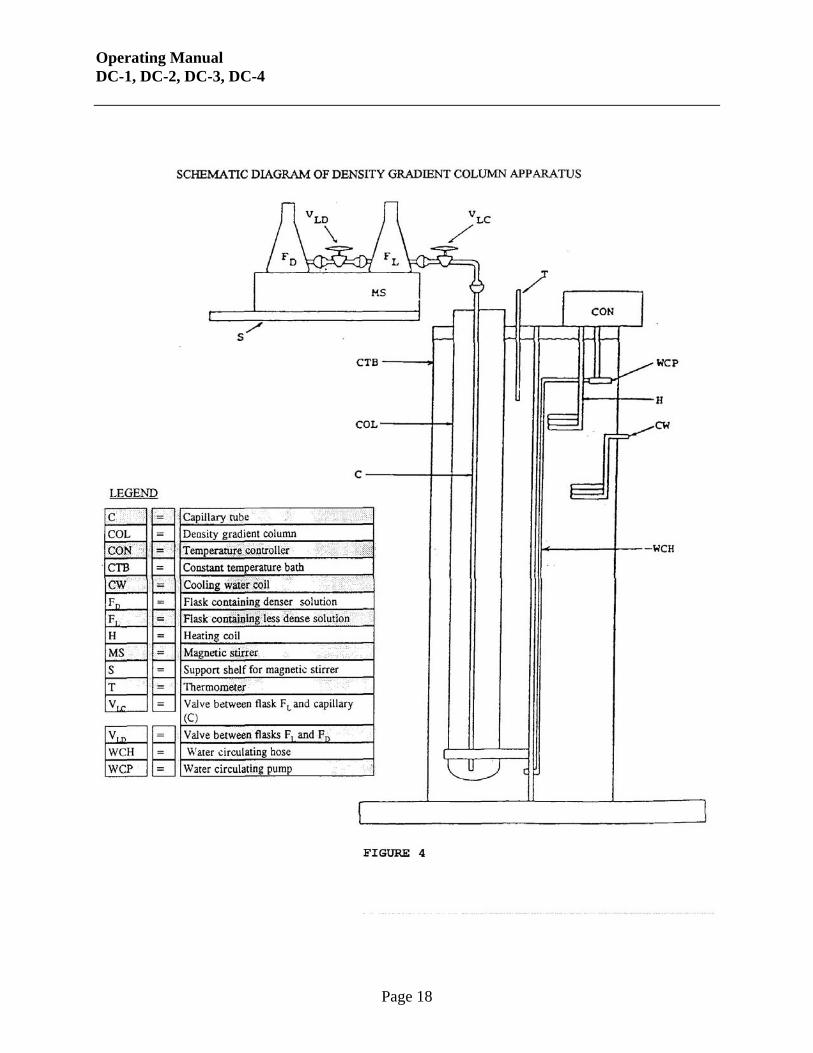
The apparatus is to be set up as per Figure 4. Add distilled or deionized water to constant temperature bath (CTB). Insert column (COL), forcing it to the support at the bottom of the bath. BAND THE COLUMN DOWN to prevent buoyancy. Finish filling CTB to within 1" of the top. Plug in the heater and set the desired temperature (e.g. 23ºC). If the ambient temperature is above 19ºC, connect the cooling water to coil (CW), and run the water at a reasonable rate. On the magnetic stirrer platform (MS), connect flasks FL and FD with Valve VLD, and attach valve VLC to FL. All joints are held together with spring-loaded joint clamps, and are lightly greased with silicone grease. With valves VLD and VLC closed, add solutions L and D to flasks FL and FD respectively. If any of the ingredients are either toxic or odiferous, both the solution preparation and the addition to the flasks should be performed in a fume hood. If the densities of L and D differ by more than 5%, then the surface heights of the two solutions should be adjusted inversely proportionate to their densities.
i.e. SL = hD SD hL where S = density h = height This can be done by using more of solution L than solution D. If in doubt, always favor the direction which will allow D to flow into L, because there is no provision for mixing in flask FD. The total volume of L plus D is about 2 liters. Put rubber stoppers in the flasks and transport them to a shelf above the apparatus. Insert capillary tube C into column (COL), then connect C to valve VLC. The capillary should extend to within 0.25cm of the bottom of the column (COL). If the solutions are toxic or odiferous, an exhaust hose must be placed near the mouths of the flasks. Once it is certain the temperature is being maintained, the gradient may be established. Remove the rubber stoppers from FL and FD, open valve VLD, and allow a few minutes for hydrostatic equilibrium to be established and for any D which flowed into L to become thoroughly mixed.
Operating Manual DC-1, DC-2, DC-3, DC-4
Page 11
Then open valve VLC to allow the fluid to flow into the column. With the valve fully open, it should take about two hours for the column to fill. If the gradient being established has a range greater than approximately 0.3 g/cm3, valve VLC should be opened slightly less than full to increase the filling time to about 4 hours. Don't worry about the initial rush of liquid when VLC is opened. The filling rate decreases rapidly as the difference in head heights becomes smaller. DO NOT adjust any of the valves after opening VLC, because this will change the flow rate and result in a non-linear gradient. After the column has filled to within 5 to 7cm ( about the 70cm mark), close valve VLC, disconnect capillary C and lift it slowly and vertically out of the gradient solution. Before releasing the calibrated floats into the column, wet them with some of solution L. The gradient should now be ready for use. After 10 minutes, plot the float density vs. column height. Discard the gradient and start over if an approximate straight line does not result. To prevent evaporation from the gradient, keep the rubber cap in place except when adding or removing materials. Remove the exhaust hose, if in use, from flasks FL and FD to the top of the column. SAMPLE IDENTIFICATION Before inserting samples into the column, a ready means of identification is needed. Labelling is not possible because this will affect the density. The easiest method for identification is to cut the specimens into different geometric shapes with an easily identifiable center of gravity. If the material of interest does not lend itself to this technique (e. g. fibers), another identification method may be used. One technique is to cut each specimen a different length. Difficulties in unambiguous identification can result because the column is essentially a hemispherical magnifier having different magnifications at the thickest portion than at the edges. Minimum length increments seem to be about 0.5cm, and even then the column must be examined from several angles to identify the specimens. The column i. d. is only 5cm so 2.5 to 3.0cm is the maximum specimen length. MEASUREMENT OF DENSITY Samples must be clean. Handle with gloves or forceps to avoid contamination problems. Skin oils can make a significant difference in the measured density. If the specimens are "compressible", care must be taken not to increase their density with excessive force on the forceps or in tying knots. Wet the specimen with solution L, either by dipping in a beaker or by immersing in the top of the gradient. Carefully immerse the sample in the top of the gradient, examine it to be certain there are no small air bubbles attached, then release it. The specimen will sink until its density is the same as that of the fluid in the gradient.
Operating Manual DC-1, DC-2, DC-3, DC-4
Page 12
There are two main reasons why this sinking may take several hours. First, as the density of the specimen approaches that of the fluid, the net force causing it to sink decreases. Second, porous specimens contain some less dense fluid in their pores, and the exchange of this material with the more dense fluid around the specimen is diffusion limited. The recommended time before determining the density is 12 hours. From the data presented in this report, it can be seen that reading the density of fibers in a column spanning a density range of 1.5 to 1.9, the density obtained at 4 hours is generally within +/- 0.01 of that obtained at more than 12 hours. Therefore, for quick results and when density is only needed to +/- 0.01, a reading at 4 hours is acceptable. For more accurate results, take a reading after letting the specimens settle for at least 12 hours. Note that only a few specimens should be inserted in the column at one time (e.g. 4/hour) to minimize the chance of their becoming entangled. Should specimens become entwined, prod them gently with a fine, straight piece of wire. To determine the density, read the column height of the specimen from the scale engraved on the column, and determine the corresponding density from the calibration curve of the density vs. column height on the calibrated glass floats. This curve should be good for a few weeks, but check it daily to be certain nothing has disturbed the gradient.
Operating Manual DC-1, DC-2, DC-3, DC-4
Page 13
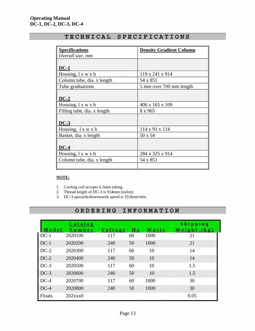
T E C H N I C A L S P E C I F I C A T I O N S
Specifications Overall size, mm
Density Gradient Column
DC-1
Housing, l x w x h 119 x 241 x 914 Column tube, dia. x length 54 x 851 Tube graduations 5 mm over 700 mm length DC-2
Housing, l x w x h 406 x 165 x 109 Filling tube, dia. x length 8 x 965 DC-3
Housing, l x w x h 114 x 91 x 114 Basket, dia. x length 50 x 54 DC-4
Housing, l x w x h 284 x 325 x 914 Column tube, dia. x length 54 x 851
NOTE:
1. Cooling coil accepts 6.3mm tubing 2. Thread length of DC-3 is 914mm (nylon) 3. DC-3 upwards/downwards speed is 19.8mm/min.