14
Operaon and Maintenance Manual for UNI-SOLAR ® PowerBond ™ ePVL

Operation and Maintenance Manual
for UNI-SOLAR® PowerBond™ ePVL

___________________________________________________________________________________________________________________________________________________________________________________________________________________________________________________________________________________________________________________________________________________________________________________________________________________________________________________________________________________________________________________________________________________________________________________________________________________________________________________________________________________________________________________________________________________________________________________________________________________________________________________________________________________
Notes
Table of Contents
United Solar Ovonic . . . . . . . . . . . . . . . . . . . . . . . . . . . . . . . . . . . . . . . . 2 Headquarters Information . . . . . . . . . . . . . . . . . . . . . . . . . . . . . . . . . . . . . . . . . . . . . . . . . . . . . . . . . 2
References . . . . . . . . . . . . . . . . . . . . . . . . . . . . . . . . . . . . . . . . . . . . . . . . . . . . . . . . . . . . . . . . . . . . . 3
Introduction . . . . . . . . . . . . . . . . . . . . . . . . . . . . . . . . . . . . . . . . . . . . . . . 4 Overview . . . . . . . . . . . . . . . . . . . . . . . . . . . . . . . . . . . . . . . . . . . . . . . . . . . . . . . . . . . . . . . . . . . . . . . 4
Tested and Certified . . . . . . . . . . . . . . . . . . . . . . . . . . . . . . . . . . . . . . . . . . . . . . . . . . . . . . . . . . . . . . 4
Disclaimer of Liability . . . . . . . . . . . . . . . . . . . . . . . . . . . . . . . . . . . . . . . . . . . . . . . . . . . . . . . . . . . . . 4
Limited Warranty . . . . . . . . . . . . . . . . . . . . . . . . . . . . . . . . . . . . . . . . . . . . . . . . . . . . . . . . . . . . . . . . . 4
Contact . . . . . . . . . . . . . . . . . . . . . . . . . . . . . . . . . . . . . . . . . . . . . . . . . . . . . . . . . . . . . . . . . . . . . . . . 4
Safety Warnings and Cautions . . . . . . . . . . . . . . . . . . . . . . . . . . . . . . . . 5 General . . . . . . . . . . . . . . . . . . . . . . . . . . . . . . . . . . . . . . . . . . . . . . . . . . . . . . . . . . . . . . . . . . . . . . . . 5
Work Site . . . . . . . . . . . . . . . . . . . . . . . . . . . . . . . . . . . . . . . . . . . . . . . . . . . . . . . . . . . . . . . . . . . . . . . 5
Additional . . . . . . . . . . . . . . . . . . . . . . . . . . . . . . . . . . . . . . . . . . . . . . . . . . . . . . . . . . . . . . . . . . . . . . . 5
How Grid Connected PV Systems Work . . . . . . . . . . . . . . . . . . . . . . . . 6
Pre-Commissioning Tests . . . . . . . . . . . . . . . . . . . . . . . . . . . . . . . . . . . . 6 Visual Audit . . . . . . . . . . . . . . . . . . . . . . . . . . . . . . . . . . . . . . . . . . . . . . . . . . . . . . . . . . . . . . . . . . . . . 6
Electrical Connections Verification . . . . . . . . . . . . . . . . . . . . . . . . . . . . . . . . . . . . . . . . . . . . . . . . . 7
System Performance Verification . . . . . . . . . . . . . . . . . . . . . . . . . . . . . . . . . . . . . . . . . . . . . . . . . . . 8
Inspection / Routine Maintenance . . . . . . . . . . . . . . . . . . . . . . . . . . . . . 8
Maintenance Verifications . . . . . . . . . . . . . . . . . . . . . . . . . . . . . . . . . . . 9 Repair of Surface Damage . . . . . . . . . . . . . . . . . . . . . . . . . . . . . . . . . . . . . . . . . . . . . . . . . . . . . . . 11
When to Clean . . . . . . . . . . . . . . . . . . . . . . . . . . . . . . . . . . . . . . . . . . . . . . . . . . . . . . . . . . . . . . . . . . 10
Cleaning Process . . . . . . . . . . . . . . . . . . . . . . . . . . . . . . . . . . . . . . . . . 10 Recommendations . . . . . . . . . . . . . . . . . . . . . . . . . . . . . . . . . . . . . . . . . . . . . . . . . . . . . . . . . . . . . . 10
Precautions for High Snow Areas . . . . . . . . . . . . . . . . . . . . . . . . . . . . . . . . . . . . . . . . . . . . . . . . . . 11
Rooftop Snow Removal . . . . . . . . . . . . . . . . . . . . . . . . . . . . . . . . . . . . . . . . . . . . . . . . . . . . . . . . . . 11
Precautions for High Temperature Areas . . . . . . . . . . . . . . . . . . . . . . . . . . . . . . . . . . . . . . . . . . . 11
1 AA6 3634-02

2 AA6 3634-02
United Solar Global Contact Information
GLOBAL HEADQUARTERS
3800 Lapeer Road
Auburn Hills, MI 48326 USA
Toll-Free Phone: 1 .800 .843 .3892 Phone: 1 .248 .475 .0100 Fax: 1 .248 .364 .0510 Email: info@uni-solar .com Web: www .uni-solar .com
EUROPEAN HEADQUARTERS
Paris, France
franceinfo@uni-solar .com
GERMAN SALES OFFICE
Mainz
europeinfo@uni-solar .com
ITALIAN SALES OFFICE
Verona
italyinfo@uni-solar .com

3 AA6 3634-02
The following references can help you determine the appropriate bonding and installation approach for your system:
References IEC 61140 Protection against electric shock, common aspects for installation and equipment
IEC 62548 Installation and safety requirements for photovoltaic (PV) generators
NFPA70 Article 690 Solar photovoltaic systems National Electric Code in the U.S.
CSA 22.1 Safety standard for electrical standards, Part 1 of the Canadian Electrical Code
This document must be read and understood before attempting to handle, install, wire, operate, and/or perform maintenance to the laminates and ePVL system. The laminates produce DC electricity when exposed to sunlight or other light sources. Contact with electrically active parts of the laminates can cause injury or death, whether they are connected to other laminates or individually. The installer assumes any risk of personal injury or property damage that might occur during the installation and handling of laminates or the ePVL system.
!∆WARNING
To avoid product damage, personal injury, or even possible death, anyone installing or handling the laminates and/or ePVL system must carefully read, understand, and follow all the installation and safety instructions in this document before attempting to install, wire, operate the array, and/or perform maintenance on the laminates.
!∆WARNING
!∆CAUTIONObserve all electrical safety precautions to prevent electrical shock while installing laminates, and while wiring, testing, and/or performing maintenance of the PV array. Use insulated tools and proper personal protective equipment to reduce the risk of electric shock.
4 AA6 3634-02
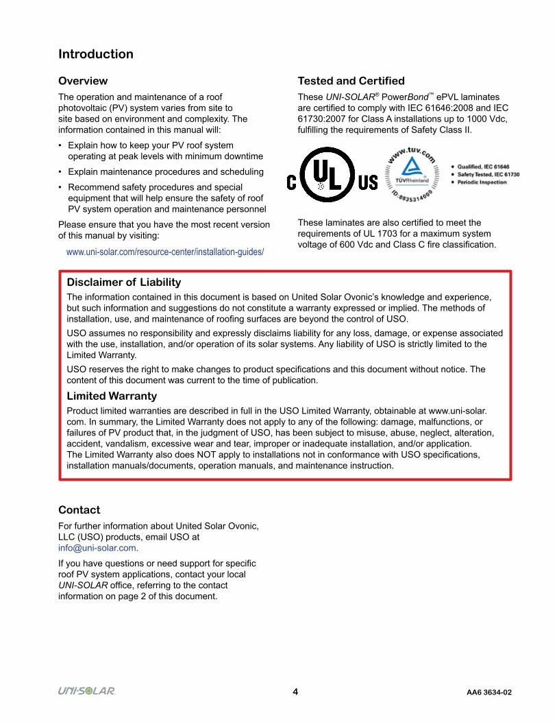
Tested and CertifiedThese UNI-SOLAR® PowerBond™ ePVL laminates are certified to comply with IEC 61646:2008 and IEC 61730:2007 for Class A installations up to 1000 Vdc, fulfilling the requirements of Safety Class II.
These laminates are also certified to meet the requirements of UL 1703 for a maximum system voltage of 600 Vdc and Class C fire classification.
Introduction
OverviewThe operation and maintenance of a roof photovoltaic (PV) system varies from site to site based on environment and complexity. The information contained in this manual will:
• Explain how to keep your PV roof system operating at peak levels with minimum downtime
• Explain maintenance procedures and scheduling
• Recommend safety procedures and special equipment that will help ensure the safety of roof PV system operation and maintenance personnel
Please ensure that you have the most recent version of this manual by visiting:
www.uni-solar.com/resource-center/installation-guides/
Disclaimer of LiabilityThe information contained in this document is based on United Solar Ovonic’s knowledge and experience, but such information and suggestions do not constitute a warranty expressed or implied. The methods of installation, use, and maintenance of roofing surfaces are beyond the control of USO.USO assumes no responsibility and expressly disclaims liability for any loss, damage, or expense associated with the use, installation, and/or operation of its solar systems. Any liability of USO is strictly limited to the Limited Warranty.USO reserves the right to make changes to product specifications and this document without notice. The content of this document was current to the time of publication.
Limited WarrantyProduct limited warranties are described in full in the USO Limited Warranty, obtainable at www.uni-solar.com. In summary, the Limited Warranty does not apply to any of the following: damage, malfunctions, or failures of PV product that, in the judgment of USO, has been subject to misuse, abuse, neglect, alteration, accident, vandalism, excessive wear and tear, improper or inadequate installation, and/or application. The Limited Warranty also does NOT apply to installations not in conformance with USO specifications, installation manuals/documents, operation manuals, and maintenance instruction.
ContactFor further information about United Solar Ovonic, LLC (USO) products, email USO at [email protected].
If you have questions or need support for specific roof PV system applications, contact your local UNI-SOLAR office, referring to the contact information on page 2 of this document.

5 AA6 3634-02
Safety Warnings and Cautions
General• Installation of UNI-SOLAR products must be
in accordance with NFPA 70, Article 650, Solar Photovoltaic Systems, of the National Electric Code of the United States, or CSA 22.1 Safety Standard for Electrical Installations, Part 1 of the Canadian Electrical Code
• Potentially lethal DC voltages can be generated whenever laminates are exposed to a light source, therefore, avoid contact with electrically active parts and be sure to isolate live circuits before attempting to make or break any connections
• Do NOT proceed if any doubt arises about the correct or safe method of performing any of the procedures found in this document
• Always wear appropriate safety and protective equipment, such as:
– Rubber soled shoes
– Cut resistant and chemical resistant gloves
– Safety glasses
– Hard hat
• When working on electrical connections, remove all metallic jewelry, and use insulated tools
• Wear cut resistant gloves whenever handling laminates
• UNI-SOLAR laminates contain electrical components enclosed and protected within. Do NOT cut or trim or alter them in any way. Do NOT drive screws into any part of the photovoltaic laminate. Altering the laminate or improper installation could cause electric shock, may result in fire, and will void the product Limited Warranty. In extreme cases where additional fixation of the laminate to the substrate is required, consult your USO representative to learn about approved options
Work Site• Follow all appropriate safety practices for the site
• Do NOT handle PV laminate assemblies in high wind conditions
• Do NOT perform maintenance on this product when laminates are wet or are in standing water
• Ensure that the work area is clear of trip hazards. Personal injury can result from tripping over power cords, tools, electrical conduit, natural gas lines, and/or installation materials
• Provide clear warning signage at each access point to the installation. This signage should clearly state the dangers associated with a high voltage solar system, the personal protection equipment that should be worn, and emergency telephone numbers for fire and emergency medical service
Additional• Scratches to the front surface of PV laminates that
may occur during transportation and installation are NOT covered by the USO Limited Warranty
• Try NOT to walk or kneel on the laminates. Wear clean (free from small stones) soft soled shoes to avoid possible scratching of the front surface of the laminates
• Avoid dropping sharp objects or placing objects on the laminates, and do NOT wheel carts or drag items across them
• PV laminates contain electrical components, and cannot be trimmed or altered in any way
• Do NOT connect or disconnect quick connect cables under load
• To reduce the risk of electric shock or arc flash, cover laminates with an opaque material before making wiring connections
• All test equipment, leads, and probes must be rated for maximum system voltage
• Observe proper polarity when connecting laminates into an electrical circuit, as reverse connections may damage the laminates and will void the product Limited Warranty
• Do NOT attempt to concentrate sunlight (via lenses, mirrors, etc.) on the laminates to increase output, as damage may occur, which will void the product Limited Warranty
• Follow all roof manufacturer and material safety data sheet (MSDS) instructions for the safe use of any chemicals
• Do NOT use any chemical agents on or around laminates that are NOT approved by USO
• Do NOT use the laminate cables to lift or maneuver the laminate
6 AA6 3634-02
With today’s technology, a photovoltaic (electric) system operates automatically and requires very little day-to-day supervision.
The solar array generates DC electricity whenever it is subjected to light. The inverter turns ON automatically whenever sufficient energy is produced to convert DC power from the solar array into grid quality AC power.
Similarly, when there is little or no DC energy coming from the solar modules (for example, at sunset), the inverter will go into a “sleep” mode until it detects that the solar array is again generating energy.
The inverter also continuously monitors the quality of the utility line and automatically switches itself OFF if it detects that utility power is outside acceptable limits. The inverter will reconnect itself when this irregular condition has been corrected.
Pre-Commissioning Tests
Prior to a full test by local electrical authorities, the installer should conduct a pre-test to verify that the system is correctly installed and suitable for connection.
This pre-test should include the following three tasks:
• A visual audit of the installation
• Verification of electrical connections
• Verification of system performance once the system has been connected
Visual AuditPerforming a visual audit of the solar array at the completion of installation is important, as this will provide a good baseline for future operation and maintenance visits.
• Ensure that appropriate safety signs are in place at each access point to the installation
• Record the serial number of each laminate, it’s location on the roof, and to which combiner box and inverter each laminate is connected
• Check that each laminate is bonded perfectly to the substrate. If any areas of the laminate are NOT perfectly bonded, mark the product with a permanent marker or crayon to flag an area to be repaired or monitored during subsequent maintenance
• Check the front surface of the laminate for any scratches or surface damage that may have occurred during installation. Contact your USO representative immediately for repair guidelines
• Clean any laminates which are particularly dirty before performing electrical checks. Excessive dirt, debris, or film on the laminates will limit performance and create false test results
• Verify that all laminates are located in areas that have minimal shading
• Verify that all laminates are located in areas which are not subject to water pooling
• Verify that the cables are appropriate for outdoor use, fit properly in a cable duct, and are NOT in standing water
• Inspect cables to verify that the connections are tight
• If the DC system is floating (not earthed or grounded), then fuses should be connected in both the positive and negative poles
• Verify that appropriate string fuses (max. 10A) are in place and that these are located in each pole of the string
• For systems that require grounding, verify that there is continuity between all metallic substrates and that the ground connection is correct
• Fill in the warranty registration form and attach a list of laminate serial numbers
• Ensure that the drainage system is unblocked
How Grid Connected PV Systems Work
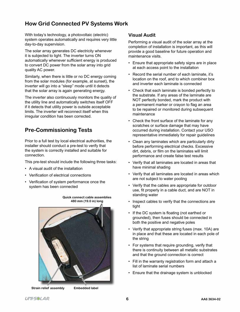
Quick connect cable assemblies 480 mm (19 .0 in) long
Embedded labelStrain relief assembly
7 AA6 3634-02
Electrical Connections VerificationThe following tests should only be performed by qualified personnel who are familiar with working on high voltage solar power systems and understand local electrical code requirements.
The best weather conditions that will provide the most accurate system verification tests are cloudless days with strong sun conditions.
Before performing any of the following tests, ensure that:
• All DC isolation switches are open (OFF)
• All string fuses have been removed
• All test equipment, leads, and probes are rated for maximum system voltage
• The inverter is switched OFF
Tag each box with a warning sign to signify that work on the PV system is in progress, locking OFF switches, if possible.
Record the total number of PowerBond ePVL laminates connected to each array combiner box, and note how the system is configured.
• Verify that the number of laminates in series does NOT exceed the maximum system voltage as dictated by local codes (NEC/IEC) or the maximum input voltage of the inverter
• Measure and record the open circuit voltage of each series string, verifying that all strings that are feeding the inverter’s mpp tracker have the same polarity and a similar open circuit voltage. It is easier to perform this test in the array combiner box or fuse box
• If the variation in string voltages is significant, or if the string delivers 0V, there is either a short or an open circuit within the string, requiring a check of each individual module
• Differences in string voltage can be due to a misconnection of the laminates. Check that the correct number of laminates is connected in series and that each laminate is providing correct voltage. To test for the latter, laminates need to be disconnected and the voltage checked directly across the module
• Verify that the polarity of each string is the same. A reversed string or module can result in damage to the product or protection circuits
– Reversed polarity on an inverter can cause damage that is NOT covered by the USO product Limited Warranty
In addition to checking voltage across the series string, it is important to verify insulation resistance (Riso) from both positive and negative poles of the string to ground. This can be accomplished with a megger meter.
• Close fuse switches in the DC disconnect switch combiner box
• Check open circuit voltage at the DC disconnect switch to ensure it is within proper limits, per the manufacturer’s installation manual
• Close each switch after each test, except for the final switch before the inverter
• Follow the proper inverter startup procedure from the inverter manufacturer’s installation manual
8 AA6 3634-02
System Performance VerificationOnce you have validated that the solar array has been correctly wired and configured, the final step is to verify that the system is performing properly.
The following tests can only be performed once the inverter has been connected into the circuit and commissioned in accordance with manufacturer instructions.
These tests, together with the majority of the checks included in the visual audit, should be performed every time there is an operation and maintenance visit.
• Measure and record the operating voltage of each series string and verify that all strings feeding the same inverter have a similar operating voltage (within ± 5V of each other). Any difference greater than 5V between strings needs to be investigated
• Measure and record the operating current of each series string and verify that all strings with the same number of laminates, have a similar operating current (within ± 1A of each other). A variation in operating current can indicate areas of the array which are shaded or need cleaning
• Check the alarm status of each inverter
• Record DC and AC power at the input and output of the inverter, and determine inverter operating efficiency
• Perform and record insulation resistance (Riso) on the input to each inverter
Inspection / Routine Maintenance
A grid connected solar system is a potentially dangerous, high voltage electrical generator. It should be inspected at least every six (6) months to ensure that all system components are working correctly.
Proper maintenance should occur at least before the onset of both summer and winter.
If your system is fitted with monitoring software, this can give you advance warning of potential problems. This can give you the opportunity to perform corrective action before a problem becomes serious.
Ground fault alarms should always be investigated.
On each operation and maintenance visit, the following should be validated:
• Ensure that appropriate safety signs are in place at each access point to the installation
• Check that each laminate is bonded perfectly to the substrate. If any areas of the laminate are NOT perfectly bonded, mark the product with a permanent marker or crayon. If this de-bonding gets worse over subsequent maintenance visits, then contact your USO representative for repair advice
• Check the top surface of each laminate for any scratches or surface damage. Patch any surface damage in accordance with USO repair guidelines (contact your USO representative) without delay
9 AA6 3634-02
• Inspect cables, verifying that adequate strain relief is provided and the connections are tight
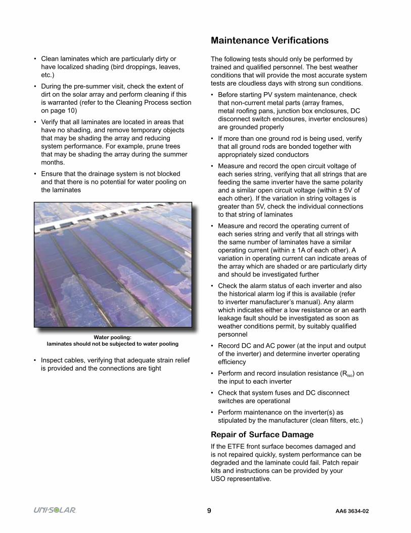
Water pooling: laminates should not be subjected to water pooling
• Clean laminates which are particularly dirty or have localized shading (bird droppings, leaves, etc.)
• During the pre-summer visit, check the extent of dirt on the solar array and perform cleaning if this is warranted (refer to the Cleaning Process section on page 10)
• Verify that all laminates are located in areas that have no shading, and remove temporary objects that may be shading the array and reducing system performance. For example, prune trees that may be shading the array during the summer months.
• Ensure that the drainage system is not blocked and that there is no potential for water pooling on the laminates
Maintenance Verifications
The following tests should only be performed by trained and qualified personnel. The best weather conditions that will provide the most accurate system tests are cloudless days with strong sun conditions.
• Before starting PV system maintenance, check that non-current metal parts (array frames, metal roofing pans, junction box enclosures, DC disconnect switch enclosures, inverter enclosures) are grounded properly
• If more than one ground rod is being used, verify that all ground rods are bonded together with appropriately sized conductors
• Measure and record the open circuit voltage of each series string, verifying that all strings that are feeding the same inverter have the same polarity and a similar open circuit voltage (within ± 5V of each other). If the variation in string voltages is greater than 5V, check the individual connections to that string of laminates
• Measure and record the operating current of each series string and verify that all strings with the same number of laminates have a similar operating current (within ± 1A of each other). A variation in operating current can indicate areas of the array which are shaded or are particularly dirty and should be investigated further
• Check the alarm status of each inverter and also the historical alarm log if this is available (refer to inverter manufacturer’s manual). Any alarm which indicates either a low resistance or an earth leakage fault should be investigated as soon as weather conditions permit, by suitably qualified personnel
• Record DC and AC power (at the input and output of the inverter) and determine inverter operating efficiency
• Perform and record insulation resistance (Riso) on the input to each inverter
• Check that system fuses and DC disconnect switches are operational
• Perform maintenance on the inverter(s) as stipulated by the manufacturer (clean filters, etc.)
Repair of Surface DamageIf the ETFE front surface becomes damaged and is not repaired quickly, system performance can be degraded and the laminate could fail. Patch repair kits and instructions can be provided by your USO representative.

10 AA6 3634-02
Cleaning Process
Recommendations• Wear rubber soled boots and cut resistant gloves
when cleaning laminates
• Survey the roof for any loose wires, damaged modules, and tough stains that will require special attention
• While surveying, remove all larger debris from the roof surface
• Use a leaf blower to remove all smaller size debris from the roof surface
• Use a garden hose to get the entire PV laminate wet, making sure not to spray water on electrical wires
When to CleanThe amount of electricity generated by a solar cell is proportional to the amount of light falling on it. A shaded cell will produce less energy.
The non-stick ETFE front surface of UNI-SOLAR PowerBond ePVL products promotes automatic self-cleaning. It is normally NOT necessary to perform an all encompassing cleaning of dirt from the solar array, provided that the array is installed on more than a 5% slope.
Punctual cleaning should be performed on any panels that are excessively affected by a collection of bird droppings, dirt, or miscellaneous debris, such as fallen leaves. This punctual cleaning should be performed at each maintenance visit.
The monetary value of cleaning dirt and debris from the array is a trade-off between the cost of the cleaning, increased energy production as a result of the cleaning, and the inevitable re-soiling of the laminates over time once they have been cleaned.
To help determine the performance benefit of cleaning, perform the following steps to measure the short circuit current of individual laminates before and after cleaning:
Measure and record the operating voltage of each series string and verify that all strings feeding the same inverter have a similar operating voltage (within ± 5V of each other). Any difference greater than 5V between strings needs to be investigated.
• Isolate a single string, making sure all the DC isolation switches are open (OFF) and all the string fuses have been removed
• Disconnect the laminates that will be used for the test by opening connections via an MC4 disconnect tool
• Verify that the current sunlight is effectively constant (clear sky, strong sunshine, no clouds)
• Connect a DC multimeter across the terminals (10A or greater) to measure and record short circuit current
• Clean the laminate as described on page 10
• Measure and record the current and verify the percent difference between the two readings. This percent difference is the potential gain that will be derived from cleaning the product
• Pressurized power washers should NOT be used directly on the laminates. If these devices are being used to clean the roof around a solar array, ensure that the nozzle of the power washer remains at least two feet away from the surface of the laminates at all times while cleaning
• When spraying a module, do NOT spray water directly on the electrical connections
11 AA6 3634-02
Precautions for High Snow AreasIf the product is installed in areas classed as high snow risk, and the roof slope is greater than 60°(x%), then additional edge protection should be fitted to the upper edge of all laminates. This added protection serves to protect the bond between the substrate and laminate from sliding snow and ice, helping to ensure long-term reliability.
Edge protection kits are available from your USO representative.
Rooftop Snow RemovalPotentially lethal voltages are present in a grid-connected solar system. If the concentration of snow on the solar installation needs to be removed, special care needs to be taken to protect the front surface of the laminates and connections from damage.
Snow removal precautions:
• Clearly mark skylights and any other hazardous areas with snow poles
• Identify the location of trip hazards, such as combiner boxes and cable trays, with snow poles
• Ensure that all drains, gutters, and downspouts are clear and operating properly
• Do NOT use tools or snow removal equipment with sharp edges or surfaces that could scratch the laminate surface
• Use a snow pole, marked at 15 cm (6 in) from the base, as a guide to determine the depth of the snow
• Remove the snow down to but NOT below the 15 cm (6 in) mark. Removing snow below this height could potentially damage the laminates and/or system components
Precautions for High Temperature AreasIn areas where high temperatures are common and/or can exceed 85°C (185°F), and the roof slope is greater than 20°, additional bonding solutions may be required. During maintenance, check for de-bonding or slippage of laminates, contacting your USO representative for further assistance, if needed.
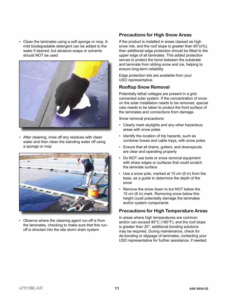
• Clean the laminates using a soft sponge or mop. A mild biodegradable detergent can be added to the water if desired, but abrasive soaps or solvents should NOT be used
• After cleaning, rinse off any residues with clean water and then clean the standing water off using a sponge or mop
• Observe where the cleaning agent run-off is from the laminates, checking to make sure that this run-off is directed into the site storm drain system