106
Operation Maintenance and Installation Manual © 2016 Mercury Marine 9.9/15/18 (2-Stroke) 8M0118482 416 eng

OperationMaintenance
andInstallation
Manual
© 2
016
Mer
cury
Mar
ine
9.9/
15/1
8 (2
-Stro
ke)
8M01
1848
2
416
eng

eng

WelcomeYou have selected one of the finest marine power packages available. Itincorporates numerous design features to ensure operating ease and durability.With proper care and maintenance, you will enjoy using this product for manyboating seasons. To ensure maximum performance and carefree use, we askthat you thoroughly read this manual.The Operation and Maintenance Manual contains specific instructions for usingand maintaining your product. We suggest that this manual remain with theproduct for ready reference whenever you are on the water.Thank you for purchasing one of our products. We sincerely hope your boatingwill be pleasant!Mercury Marine, Fond du Lac, Wisconsin, U.S.A.
Name / function:John Pfeifer, President,Mercury Marine
Read This Manual ThoroughlyIMPORTANT: If you do not understand any portion of this manual, contact yourdealer. Your dealer can also provide a demonstration of actual starting andoperating procedures.
NoticeThroughout this publication, and on your power package, warnings, cautions,
and notices, accompanied by the International Hazard Symbol ! , may beused to alert the installer and user to special instructions concerning aparticular service or operation that may be hazardous if performed incorrectlyor carelessly. Observe them carefully.These safety alerts alone cannot eliminate the hazards that they signal. Strictcompliance with these special instructions while performing the service, pluscommon sense operation, are major accident prevention measures.
! WARNINGIndicates a hazardous situation which, if not avoided, could result in death orserious injury.
! CAUTIONIndicates a hazardous situation which, if not avoided, could result in minor ormoderate injury.
eng i

NOTICEIndicates a situation which, if not avoided, could result in engine or majorcomponent failure.
IMPORTANT: Identifies information essential to the successful completion ofthe task.NOTE: Indicates information that helps in the understanding of a particular stepor action.IMPORTANT: The operator (driver) is responsible for the correct and safeoperation of the boat, the equipment aboard, and the safety of all occupantsaboard. We strongly recommend that the operator read this Operation andMaintenance Manual and thoroughly understand the operational instructions forthe power package and all related accessories before the boat is used.
! WARNINGThe engine exhaust from this product contains chemicals known to the stateof California to cause cancer, birth defects or other reproductive harm.
The serial numbers are the manufacturer’s keys to numerous engineeringdetails that apply to your Mercury Marine power package. When contactingMercury Marine about service, always specify model and serial numbers.Descriptions and specifications contained herein were in effect at the time thiswas approved for printing. Mercury Marine, whose policies are based oncontinuous improvement, reserves the right to discontinue models at any timeor to change specifications or designs without notice and without incurringobligation.
Warranty MessageThe product you have purchased comes with a limited warranty from MercuryMarine; the terms of the warranty are set forth in the Warranty Manual includedwith the product. The Warranty Manual contains a description of what iscovered, what is not covered, the duration of coverage, how to best obtainwarranty coverage, important disclaimers and limitations of damages, andother related information. Please review this important information.
Copyright and Trademark Information© MERCURY MARINE. All rights reserved. Reproduction in whole or inpart without permission is prohibited.Alpha, Axius, Bravo One, Bravo Two, Bravo Three, Circle M with Waves Logo,K‑planes, Mariner, MerCathode, MerCruiser, Mercury, Mercury with WavesLogo, Mercury Marine, Mercury Precision Parts, Mercury Propellers, MercuryRacing, MotorGuide, OptiMax, Quicksilver, SeaCore, Skyhook, SmartCraft,Sport‑Jet, Verado, VesselView, Zero Effort, Zeus, #1 On the Water and We'reDriven to Win are registered trademarks of Brunswick Corporation. Pro XS is atrademark of Brunswick Corporation. Mercury Product Protection is a registeredservice mark of Brunswick Corporation.
ii eng

Identification RecordsPlease record the following applicable information:
OutboardEngine Model and HorsepowerEngine Serial NumberGear RatioPropeller Number Pitch Diameter Hull Identification Number (HIN) Purchase Date Boat Manufacturer Boat Model Length Exhaust Gas Emissions Certification Number (Europe Only)
eng iii

eng iv

General Information
Boater's Responsibilities..................................................................................... 1Before Operating Your Outboard........................................................................ 1Boat Horsepower Capacity................................................................................. 1Outboard Remote Control Models ..................................................................... 2Remote Steering Notice......................................................................................2Lanyard Stop Switch........................................................................................... 3Protecting People in the Water........................................................................... 6Passenger Safety Message ‑ Pontoon Boats and Deck Boats...........................6Wave and Wake Jumping................................................................................... 8Impact with Underwater Hazards........................................................................9Safety Instructions for Hand‑Tilled Outboards.................................................. 10Exhaust Emissions........................................................................................... 10Selecting Accessories for Your Outboard......................................................... 12Safe Boating Recommendations...................................................................... 12Recording Serial Number................................................................................. 14Specifications....................................................................................................16Component Identification.................................................................................. 20Associated Parts............................................................................................... 25
Transporting
Removing the Motor......................................................................................... 26Carrying the Motor............................................................................................ 26Storing the Motor.............................................................................................. 26Trailering Boat/Outboard.................................................................................. 27Transporting Portable Fuel Tanks.................................................................... 28
Fuel and Oil
Fuel Requirements........................................................................................... 29Oil Recommendation........................................................................................ 30Mixing Fuel and Oil........................................................................................... 30Engine Break‑In................................................................................................ 31Filling Fuel Tank............................................................................................... 31
eng v

Features and Controls
Remote Control Features................................................................................. 32Tilt Up and Tilt Down........................................................................................ 32Shallow Water Operation.................................................................................. 34Trim Angle Adjustment..................................................................................... 35Steering Friction Adjustment.............................................................................36Throttle Grip Turning Friction Adjustment......................................................... 37Trim Tab Adjustment........................................................................................ 37
Operation
Prestarting Check List.......................................................................................40Operating in Freezing Temperatures................................................................ 40Operating in Saltwater or Polluted Water......................................................... 40Operating at High Elevations............................................................................ 41Operating Outboard as an Auxiliary Engine..................................................... 41Prestarting Instructions..................................................................................... 41Engine Break‑In Procedure.............................................................................. 42Warming Up the Engine....................................................................................43Starting the Engine........................................................................................... 44Gear Shifting..................................................................................................... 47Stopping the Engine......................................................................................... 49Emergency Starting.......................................................................................... 51
Maintenance
Outboard Care.................................................................................................. 53Inspection and Maintenance Schedule............................................................. 53Flushing the Cooling System............................................................................ 54Top Cowl Removal and Installation.................................................................. 56Battery Inspection ............................................................................................ 56Fuel System...................................................................................................... 57Exterior Care.....................................................................................................58Fuse Replacement ‑ Electric Start Remote Control Models............................. 58Replacing the Anodes.......................................................................................59Propeller Replacement..................................................................................... 60Spark Plug Inspection and Replacement..........................................................63Lubrication Points............................................................................................. 64Changing Gear Oil............................................................................................ 64Submerged Outboard....................................................................................... 65
vi eng

Storage
Preseason Check............................................................................................. 66Storage Preparation..........................................................................................66Protecting External Outboard Components...................................................... 67Protecting Internal Engine Components........................................................... 67Gearcase.......................................................................................................... 67Positioning Outboard for Storage..................................................................... 67Battery Storage................................................................................................. 68
Troubleshooting
Starter Motor Will Not Crank the Engine (Electric Start Models)...................... 69Engine Will Not Start.........................................................................................69Engine Runs Erratically.................................................................................... 69Performance Loss.............................................................................................70Battery Will Not Hold Charge............................................................................ 70
Owner Service Assistance
Service Assistance........................................................................................... 71Ordering Literature............................................................................................73
Installation
Mercury Marine Validated Engine Mounting Hardware.................................... 75Installing Outboard............................................................................................75Installing the Remote Control Devices..............................................................77Wire Color Code Abbreviations........................................................................ 82Battery Installation............................................................................................ 83Propeller Selection............................................................................................84
Accessories
Propeller Table................................................................................................. 85Accessories...................................................................................................... 86
eng vii

Wiring Diagrams
MH Models........................................................................................................88EH Models........................................................................................................ 90E Models........................................................................................................... 92Single Remote Control Box.............................................................................. 94
Maintenance Log
Maintenance Log.............................................................................................. 96
viii eng

Boater's ResponsibilitiesThe operator (driver) is responsible for the correct and safe operation of theboat and the safety of its occupants and general public. It is stronglyrecommended that each operator read and understand this entire manualbefore operating the outboard.Be sure that at least one additional person onboard is instructed in the basicsof starting and operating the outboard and boat handling in case the driver isunable to operate the boat.
Before Operating Your OutboardRead this manual carefully. Learn how to operate your outboard properly. If youhave any questions, contact your dealer.Safety and operating information that is practiced, along with using goodcommon sense, can help prevent personal injury and product damage.This manual as well as safety labels posted on the outboard use the followingsafety alerts to draw your attention to special safety instructions that should befollowed.
! WARNINGIndicates a hazardous situation which, if not avoided, could result in death orserious injury.
! CAUTIONIndicates a hazardous situation which, if not avoided, could result in minor ormoderate injury.
NOTICEIndicates a situation which, if not avoided, could result in engine or majorcomponent failure.
Boat Horsepower Capacity
! WARNINGExceeding the boat's maximum horsepower rating can cause serious injuryor death. Overpowering the boat can affect boat control and flotationcharacteristics or break the transom. Do not install an engine that exceedsthe boat's maximum power rating.
GENERAL INFORMATION
eng 1

Do not overpower or overload your boat. Most boats will carry a requiredcapacity plate indicating the maximum acceptable power and load asdetermined by the manufacturer following certain federal guidelines. If in doubt,contact your dealer or the boat manufacturer.
U.S. COAST GUARD CAPACITYMAXIMUM HORSEPOWER XXXMAXIMUM PERSON CAPACITY (POUNDS) XXXMAXIMUM WEIGHT CAPACITY XXX
26777
Outboard Remote Control ModelsThe remote control connected to your outboard must be equipped with a startin neutral only protection device. This prevents the engine from starting whenthe shift is actuated in any position other than neutral.
! WARNINGStarting the engine with the drive in gear can cause serious injury or death.Never operate a boat that does not have a neutral‑safety‑protection device.
N
26838
Remote Steering Notice
! WARNINGImproper fasteners or improper installation procedures can result inloosening or disengagement of the steering link rod. This can cause asudden, unexpected loss of boat control, resulting in serious injury or deathdue to occupants being thrown within or out of the boat. Always use requiredcomponents and follow instructions and torque procedures.
GENERAL INFORMATION
2 eng

The steering link rod that connects the steering cable to the engine must befastened utilizing self‑locking nuts. These self‑locking nuts must never bereplaced with common nuts (non‑locking) as they will work loose and vibrateoff, freeing the link rod to disengage.
a - Self‑locking nuts
Lanyard Stop SwitchThe purpose of a lanyard stop switch is to turn off the engine when the operatormoves far enough away from the operator's position (as in accidental ejectionfrom the operator's position) to activate the switch. Tiller handle outboards andsome remote control units are equipped with a lanyard stop switch. A lanyardstop switch can be installed as an accessory ‑ generally on the dashboard orside adjacent to the operator's position.A decal near the lanyard stop switch is a visual reminder for the operator toattach the lanyard to their personal flotation device (PFD) or wrist.
a 3018
GENERAL INFORMATION
eng 3

The lanyard cord is usually 122–152 cm (4–5 feet) in length when stretched out,with an element on one end made to be inserted into the switch and a clip onthe other end for attaching to the operator's PFD or wrist. The lanyard is coiledto make its at‑rest condition as short as possible to minimize the likelihood oflanyard entanglement with nearby objects. Its stretched‑out length is made tominimize the likelihood of accidental activation should the operator choose tomove around in an area close to the normal operator's position. If it is desiredto have a shorter lanyard, wrap the lanyard around the operator's wrist or leg,or tie a knot in the lanyard.
a - Lanyard cord clipb - Lanyard decalc - Lanyard stop switch
Read the following Safety Information before proceeding.Important Safety Information: The purpose of a lanyard stop switch is to stopthe engine when the operator moves far enough away from the operator'sposition to activate the switch. This would occur if the operator accidentally fallsoverboard or moves within the boat a sufficient distance from the operator'sposition. Falling overboard and accidental ejections are more likely to occur incertain types of boats such as low sided inflatables, bass boats, highperformance boats, and light, sensitive handling fishing boats operated by ahand tiller. Falling overboard and accidental ejections are also likely to occur asa result of poor operating practices such as sitting on the back of the seat orgunwale at planing speeds, standing at planing speeds, sitting on elevatedfishing boat decks, operating at planing speeds in shallow or obstacle infestedwaters, releasing your grip on a steering wheel or tiller handle that is pulling inone direction, drinking alcohol or consuming drugs, or daring high speed boatmaneuvers.
ca
b
53910
OFF
RUN
ATTACH LANYARD
GENERAL INFORMATION
4 eng

While activation of the lanyard stop switch will stop the engine immediately, aboat will continue to coast for some distance depending upon the velocity anddegree of any turn at shut down. However, the boat will not complete a fullcircle. While the boat is coasting, it can cause injury to anyone in the boat'spath as seriously as the boat would when under power.We strongly recommend that other occupants be instructed on proper startingand operating procedures should they be required to operate the engine in anemergency (if the operator is accidentally ejected).
! WARNINGIf the operator falls out of the boat, stop the engine immediately to reduce thepossibility of serious injury or death from being struck by the boat. Alwaysproperly connect the operator to the stop switch using a lanyard.
! WARNINGAvoid serious injury or death from deceleration forces resulting fromaccidental or unintended stop switch activation. The boat operator shouldnever leave the operator's station without first disconnecting the stop switchlanyard from the operator.
Accidental or unintended activation of the switch during normal operation isalso a possibility. This could cause any, or all, of the following potentiallyhazardous situations:• Occupants could be thrown forward due to unexpected loss of forward
motion ‑ a particular concern for passengers in the front of the boat whocould be ejected over the bow and possibly struck by the gearcase orpropeller.
• Loss of power and directional control in heavy seas, strong current, orhigh winds.
• Loss of control when docking.
KEEP THE LANYARD STOP SWITCH AND LANYARD CORD IN GOODOPERATING CONDITIONBefore each use, check to ensure the lanyard stop switch works properly. Startthe engine and stop it by pulling the lanyard cord. If the engine does not stop,have the switch repaired before operating the boat.Before each use, visually inspect the lanyard cord to ensure it is in goodworking condition and that there are no breaks, cuts, or wear to the cord.Check that the clips on the ends of the cord are in good condition. Replace anydamaged or worn lanyard cords.
GENERAL INFORMATION
eng 5

Protecting People in the WaterWHILE YOU ARE CRUISINGIt is very difficult for a person standing or floating in the water to take quickaction to avoid a boat heading in his/her direction, even at slow speed.
21604
Always slow down and exercise extreme caution any time you are boating in anarea where there might be people in the water.Whenever a boat is moving (coasting) and the outboard gear shift is in neutralposition, there is sufficient force by the water on the propeller to cause thepropeller to rotate. This neutral propeller rotation can cause serious injury.
WHILE THE BOAT IS STATIONARY
! WARNINGA spinning propeller, a moving boat, or any solid device attached to the boatcan cause serious injury or death to swimmers. Stop the engine immediatelywhenever anyone in the water is near your boat.
Shift the outboard into neutral and shut off the engine before allowing people toswim or be in the water near your boat.
Passenger Safety Message ‑ Pontoon Boats and Deck BoatsWhenever the boat is in motion, observe the location of all passengers. Do notallow any passengers to stand or use seats other than those designated fortraveling faster than idle speed. A sudden reduction in boat speed, such asplunging into a large wave or wake, a sudden throttle reduction, or a sharpchange of boat direction, could throw them over the front of the boat. Fallingover the front of the boat between the two pontoons will position them to be runover by the outboard.
BOATS HAVING AN OPEN FRONT DECKNo one should ever be on the deck in front of the fence while the boat is inmotion. Keep all passengers behind the front fence or enclosure.
GENERAL INFORMATION
6 eng

Persons on the front deck could easily be thrown overboard or personsdangling their feet over the front edge could get their legs caught by a waveand pulled into the water.
26782
! WARNINGSitting or standing in an area of the boat not designed for passengers atspeeds above idle can cause serious injury or death. Stay back from the frontend of deck boats or raised platforms and remain seated while the boat is inmotion.
BOATS WITH FRONT MOUNTED, RAISED PEDESTAL FISHING SEATSElevated fishing seats are not intended for use when the boat is traveling fasterthan idle or trolling speed. Sit only in seats designated for traveling at fasterspeeds.Any unexpected, sudden reduction in boat speed could result in the elevatedpassenger falling over the front of the boat.
26783
GENERAL INFORMATION
eng 7

Wave and Wake JumpingOperating recreational boats over waves and wake is a natural part of boating.However, when this activity is done with sufficient speed to force the boat hullpartially or completely out of the water, certain hazards arise, particularly whenthe boat enters the water.
26784
The primary concern is the boat changing direction while in the midst of thejump. In such case, the landing may cause the boat to veer violently in a newdirection. Such a sharp change in direction can cause occupants to be thrownout of their seats, or out of the boat.
! WARNINGWave or wake jumping can cause serious injury or death from occupantsbeing thrown within or out of the boat. Avoid wave or wake jumping wheneverpossible.
There is another less common hazardous result from allowing your boat tolaunch off a wave or wake. If the bow of your boat pitches down far enoughwhile airborne, upon water contact it may penetrate under the water surfaceand submarine for an instant. This will bring the boat to a nearly instantaneousstop and can send the occupants flying forward. The boat may also steersharply to one side.
GENERAL INFORMATION
8 eng

Impact with Underwater HazardsReduce speed and proceed with caution whenever you drive a boat in shallowwater areas, or in areas where you suspect underwater obstacles may existwhich could be struck by the outboard or the boat bottom. The most importantthing you can do to help reduce injury or impact damage from striking afloating or underwater object is to control the boat speed. Under theseconditions, boat speed should be kept to a minimum planing speed of24 to 40 km/h (15 to 25 mph).
26785
Striking a floating or underwater object could result in an infinite number ofsituations. Some of these situations could result in the following:• Part of the outboard or the entire outboard could break loose and fly into
the boat.• The boat could move suddenly in a new direction. Such a sharp change in
direction can cause occupants to be thrown out of their seats or out of theboat.
• A rapid reduction in speed. This will cause occupants to be thrownforward, or even out of the boat.
• Impact damage to the outboard and/or boat.Keep in mind, the most important thing you can do to help reduce injury orimpact damage during an impact is control the boat speed. Boat speed shouldbe kept to a minimum planing speed when driving in waters known to haveunderwater obstacles.After striking a submerged object, stop the engine as soon as possible andinspect it for any broken or loose parts. If damage is present or suspected, theoutboard should be taken to an authorized dealer for a thorough inspection andnecessary repair.The boat should also be checked for any hull fractures, transom fractures, orwater leaks.Operating a damaged outboard could cause additional damage to other partsof the outboard, or could affect control of the boat. If continued running isnecessary, do so at greatly reduced speeds.
GENERAL INFORMATION
eng 9

! WARNINGOperating a boat or engine with impact damage can result in productdamage, serious injury, or death. If the vessel experiences any form ofimpact, have an authorized Mercury Marine dealer inspect and repair thevessel or power package.
Safety Instructions for Hand‑Tilled OutboardsNo person or cargo should occupy the area directly in front of the outboardwhile the boat is in motion. If an underwater obstacle is struck, the outboard willtilt up and could seriously injure anyone occupying this area.
MODELS WITH CLAMP SCREWS:Some outboards come with transom bracket clamp screws. The use of clampbracket screws alone, is insufficient to properly and safely secure the outboardto the transom. Proper installation of the outboard includes bolting the engine tothe boat through the transom. Refer to Installation ‑ Installing Outboard formore complete installation information.
! WARNINGFailure to correctly fasten the outboard could result in the outboard propellingoff the boat transom resulting in property damage, serious injury, or death.Before operation, the outboard must be correctly installed with the requiredmounting hardware.
If an obstacle is struck at planing speed and the outboard is not securelyfastened to the transom, it is possible the outboard could lift off the transomand land in the boat.
Exhaust EmissionsBE ALERT TO CARBON MONOXIDE POISONINGCarbon monoxide is present in the exhaust fumes of all internal combustionengines. This includes the outboards, sterndrives, and inboard engines thatpropel boats, as well as the generators that power various boat accessories.Carbon monoxide is a deadly gas that is odorless, colorless, and tasteless.Early symptoms of carbon monoxide poisoning which should not be confusedwith seasickness or intoxication, include headache, dizziness, drowsiness, andnausea.
! WARNINGCarbon monoxide poisoning can lead to unconsciousness, brain damage, ordeath. Keep the boat well ventilated while at rest or underway and avoidprolonged exposure to carbon monoxide.
GENERAL INFORMATION
10 eng

GOOD VENTILATIONVentilate passenger area, open side curtains or forward hatches to removefumes.
21622
Example of desired air flow through the boat
POOR VENTILATIONUnder certain running and/or wind conditions, permanently enclosed or canvasenclosed cabins or cockpits with insufficient ventilation may draw in carbonmonoxide. Install one or more carbon monoxide detectors in your boat.Although the occurrence is rare, on a very calm day, swimmers andpassengers in an enclosed area of a stationary boat that contains or is near arunning engine may be exposed to a hazardous level of carbon monoxide.
WHILE BOAT IS STATIONARY
a - Running the engine when the boat is moored in a confined spaceb - Mooring close to another boat that has its engine running
21626
ab
GENERAL INFORMATION
eng 11

WHILE BOAT IS MOVING
a - Running the boat with the trim angle of the bow too highb - Running the boat with no forward hatches open
Selecting Accessories for Your OutboardGenuine Mercury Precision or Quicksilver Accessories have been specificallydesigned and tested for your outboard. These accessories are available fromMercury Marine dealers.IMPORTANT: Check with your dealer before installing accessories. The misuseof approved accessories or the use of nonapproved accessories can damagethe product.Some accessories not manufactured or sold by Mercury Marine are notdesigned to be safely used with your outboard or outboard operating system.Acquire and read the installation, operation and maintenance manuals for allyour selected accessories.
Safe Boating RecommendationsTo safely enjoy the waterways, familiarize yourself with local and all othergovernmental boating regulations and restrictions and consider the followingsuggestions.Know and obey all nautical rules and laws of the waterways.• We recommend that all powerboat operators complete a boating safety
course. In the U.S., the U.S. Coast Guard Auxiliary, the Power Squadron,the Red Cross, and your state or provincial boating law enforcementagency provide courses. For more information in the U.S., call the BoatU.S. Foundation at 1‑800‑336‑BOAT (2628).
Perform safety checks and required maintenance.• Follow a regular schedule and ensure that all repairs are properly made.Check safety equipment onboard.• Here are some suggestions of the types of safety equipment to carry
when boating:Approved fire extinguishers
Signal devices: flashlight, rockets or flares, flag, and whistle or horn
Tools necessary for minor repairs
a b
21628
GENERAL INFORMATION
12 eng

Anchor and extra anchor line
Manual bilge pump and extra drain plugs
Drinking water
Radio
Paddle or oar
Spare propeller, thrust hubs, and an appropriate wrench
First aid kit and instructions
Waterproof storage containers
Spare operating equipment, batteries, bulbs, and fuses
Compass and map or chart of the area
Personal flotation device (one per person onboard)
Watch for signs of weather change and avoid foul weather and rough‑seaboating.Tell someone where you are going and when you expect to return.Passenger boarding.• Stop the engine whenever passengers are boarding, unloading, or are
near the back (stern) of the boat. Shifting the drive unit into neutral is notsufficient.
Use personal flotation devices.• Federal law requires that there be a U.S. Coast Guard‑approved life
jacket (personal flotation device), correctly sized and readily accessiblefor every person onboard, plus a throwable cushion or ring. We stronglyadvise that everyone wear a life jacket at all times while in the boat.
Prepare other boat operators.• Instruct at least one person onboard in the basics of starting and
operating the engine and boat handling in case the driver becomesdisabled or falls overboard.
Do not overload your boat.• Most boats are rated and certified for maximum load (weight) capacities
(refer to your boat's capacity plate). Know your boat's operating andloading limitations. Know if your boat will float if it is full of water. When indoubt, contact your authorized Mercury Marine dealer or the boatmanufacturer.
Ensure that everyone in the boat is properly seated.
GENERAL INFORMATION
eng 13

• Do not allow anyone to sit or ride on any part of the boat that was notintended for such use. This includes the backs of seats, gunwales,transom, bow, decks, raised fishing seats, and any rotating fishing seat.Passengers should not sit or ride anywhere that sudden unexpectedacceleration, sudden stopping, unexpected loss of boat control, or suddenboat movement could cause a person to be thrown overboard or into theboat. Ensure that all passengers have a proper seat and are in it beforeany boat movement.
Never operate a boat while under the influence of alcohol or drugs. It isthe law.• Alcohol or drugs can impair your judgment and greatly reduce your ability
to react quickly.Know your boating area and avoid hazardous locations.Be alert.• The operator of the boat is responsible by law to maintain a proper
lookout by sight and hearing. The operator must have an unobstructedview particularly to the front. No passengers, load, or fishing seats shouldblock the operator's view when the boat is above idle or planing transitionspeed. Watch out for others, the water, and your wake.
Never drive your boat directly behind a water skier.• Your boat traveling at 40 km/h (25 mph) will overtake a fallen skier who is
61 m (200 ft) in front of you in five seconds.Watch fallen skiers.• When using your boat for waterskiing or similar activities, always keep a
fallen or down skier on the operator's side of the boat while returning toattend to the skier. The operator should always have the down skier insight and never back up to the skier or anyone in the water.
Report accidents.• Boat operators are required by law to file a boating accident report with
their state boating law enforcement agency when their boat is involved incertain boating accidents. A boating accident must be reported if 1) thereis loss of life or probable loss of life, 2) there is personal injury requiringmedical treatment beyond first aid, 3) there is damage to boats or otherproperty where the damage value exceeds $500.00, or 4) there iscomplete loss of the boat. Seek further assistance from local lawenforcement.
Recording Serial NumberIt is important to record the serial number and other important information forfuture reference.Please record the serial number of the engine as indicated (on the lower enginecover and the cylinder block) in the space below. This number will come inhandy in the event of theft and it can help you to quickly identify the producttype.
GENERAL INFORMATION
14 eng

Serial number:Model year:Model designation:Year manufactured:Certified Europe Insignia (as applicable):
GENERAL INFORMATION
eng 15

Specifications
MODEL 9.9 MH 9.9 EHOverall length 869 mm (34.2 in.)Overall width 345 mm (13.6 in.)
Overall heightS = 1067 mm (42.0 in.)L = 1194 mm (47.0 in.)
XL = 1321 mm (52.0 in.)
Transom heightS = 435 mm (17.1 in.)L = 562 mm (22.1 in.)
XL = 689 mm (27.1 in.)
WeightS 41.0 kg (90.3 lb) 44.0 kg (97.0 lb)L 42.0 kg (92.6 lb) 45.0 kg (99.2 lb)XL 43.0 kg (94.8 lb) 46.0 kg (101.4 lb)
Output 7.3 kWMaximum operatingrange 4500–5300 RPM
Number of cylinders 2Displacement 247 ccBore x stroke 55 x 52 mm (2.1 x 2.0 in.)Exhaust system Through‑the‑hub exhaustLubrication system Engine oil mixed gasolineCooling system Thermostat controlledStarting system Manual Electric with manual backupIgnition Flywheel magneto CDI
Spark plugsNGK B7HS‑10/BR7HS‑10 or Champion L82C/
RL82Cgap 1.0 mm (0.039 in.)
Trim system Manual, 6 positions
Engine oil mixing ratioMercury/Quicksilver 2‑Stroke engine oil: Unleaded
gasoline1:50
Gear oil Mercury/Quicksilver gear oil API GL5, SAE #80–90approximately 370 mL (12.5 oz)
Fuel tank capacity 25 Liter (6.6 US gal)Gear reduction ratio 13:24 (1.84:1)
GENERAL INFORMATION
16 eng

MODEL 15 MH 15 EHOverall length 869 mm (34.2 in.)Overall width 345 mm (13.6 in.)
Overall heightS = 1067 mm (42.0 in.)L = 1194 mm (47.0 in.)
XL = 1321 mm (52.0 in.)
Transom heightS = 435 mm (17.1 in.)L = 562 mm (22.1 in.)
XL = 689 mm (27.1 in.)
WeightS 41.0 kg (90.3 lb) 44.0 kg (97.0 lb)L 42.0 kg (92.6 lb) 45.0 kg (99.2 lb)XL 43.0 kg (94.8 lb) 46.0 kg (101.4 lb)
Output 7.3 kWMaximum operatingrange 5200–5800 RPM
Number of cylinders 2Displacement 294 ccBore x stroke 55 x 52 mm (2.1 x 2.0 in.)Exhaust system Through‑the‑hub exhaustLubrication system Engine oil mixed gasolineCooling system Thermostat controlledStarting system Manual Electric with manual backupIgnition Flywheel magneto CDI
Spark plugsNGK B7HS‑10/BR7HS‑10 or Champion L82C/
RL82Cgap 1.0 mm (0.039 in.)
Trim system Manual, 6 positions
Engine oil mixing ratioMercury/Quicksilver 2‑Stroke engine oil: Unleaded
gasoline1:50
Gear oil Mercury/Quicksilver gear oil API GL5, SAE #80–90approximately 370 mL (12.5 oz)
Fuel tank capacity 25 Liter (6.6 US gal)Gear reduction ratio 13:24 (1.84:1)
GENERAL INFORMATION
eng 17

MODEL 18 MHOverall length 869 mm (34.2 in.)Overall width 345 mm (13.6 in.)
Overall heightS = 1067 mm (42.0 in.)L = 1194 mm (47.0 in.)
XL = 1321 mm (52.0 in.)
Transom heightS = 435 mm (17.1 in.)L = 562 mm (22.1 in.)
XL = 689 mm (27.1 in.)
WeightS 41.0 kg (90.3 lb)L 42.0 kg (92.6 lb)XL 43.0 kg (94.8 lb)
Output 13.2 kWMax operating range 5200–5800 RPMNumber of cylinders 2Displacement 294 ccBore x stroke 60 x 52 mm (2.3 x 2.0 in.)Exhaust system Through‑the‑hub exhaustLubrication system Engine oil mixed gasolineCooling system Thermostat controlledStarting system ManualIgnition Flywheel magneto CDI
Spark plugs NGK B7HS‑10/BR7HS‑10 or Champion L82C/RL82Cgap 1.0 mm (0.039 in.)
Trim system Manual, 6 positions
Engine oil mixingratio
Mercury/Quicksilver 2‑Stroke engine oil: Unleadedgasoline
1:50
Gear oil Mercury/Quicksilver gear oil API GL5, SAE #80–90approximately 370 mL (12.5 oz)
Fuel tank capacity 25 Liter (6.6 US gal)Gear reduction ratio 13:24 (1.84:1)
GENERAL INFORMATION
18 eng

GENERAL INFORMATIONNotes:
eng 19

Component Identification
40465
1
2
3
4
5
6
8
9
10
11
15
16
17
18
19
21
22
23
24
12
13
14
25 27 28 2926
30
20
7
GENERAL INFORMATION
20 eng

MH Models1 - Tilt handle2 - Top cowl3 - Bottom cowl4 - Reverse lock lever5 - Water pump indicator hole6 - Driveshaft housing7 - Water strainer8 - Anti‑ventilation plate9 - Anode/trim tab10 - Secondary water intake11 - Propeller12 - Oil drain plug (upper)13 - Water plug14 - Oil drain plug (lower)15 - Starter handle16 - Shift lever17 - Stop switch18 - Starter switch button19 - Choke knob20 - Fuel hose connector21 - Throttle grip22 - Clamp screws23 - Transom brackets24 - Thrust rod25 - Primer bulb26 - Fuel pickup elbow27 - Fuel connector28 - Fuel tank cap29 - Air vent screw30 - Fuel tank
GENERAL INFORMATION
eng 21
40466
1
2
3
4
5
6
8
9
10
11
15
16
17
18
19
21
22
23
24
12
13
14
26 28 29 3027
31
20
7
25
GENERAL INFORMATION
22 eng

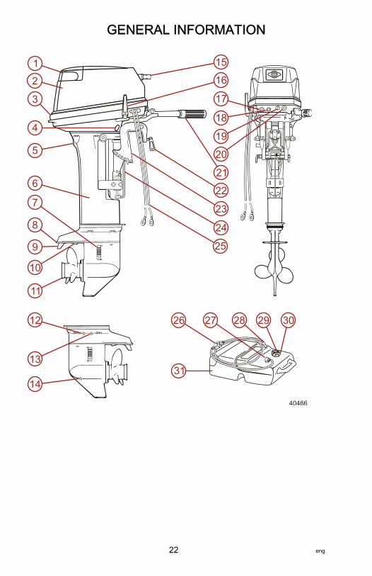
EH Models1 - Tilt handle2 - Top cowl3 - Bottom cowl4 - Reverse lock lever5 - Water pump indicator hole6 - Driveshaft housing7 - Water strainer8 - Anti‑ventilation plate9 - Anode/trim tab10 - Secondary water intake11 - Propeller12 - Oil drain plug (upper)13 - Water plug14 - Oil drain plug (lower)15 - Starter handle16 - Shift lever17 - Stop switch18 - Starter switch button19 - Choke knob20 - Fuel hose connector21 - Throttle grip22 - Clamp screws23 - Transom brackets24 - Thrust rod25 - Battery cables26 - Primer bulb27 - Fuel pickup elbow28 - Fuel connector29 - Fuel tank cap30 - Air vent screw31 - Fuel tank
GENERAL INFORMATION
eng 23
40467
1
2
3
4
5
6
8
9
10
11
15
16
17
18
19
21
22
23
24
12
13
14
26 28 29 3027
31
20
7
25
32
33
34
35
GENERAL INFORMATION
24 eng

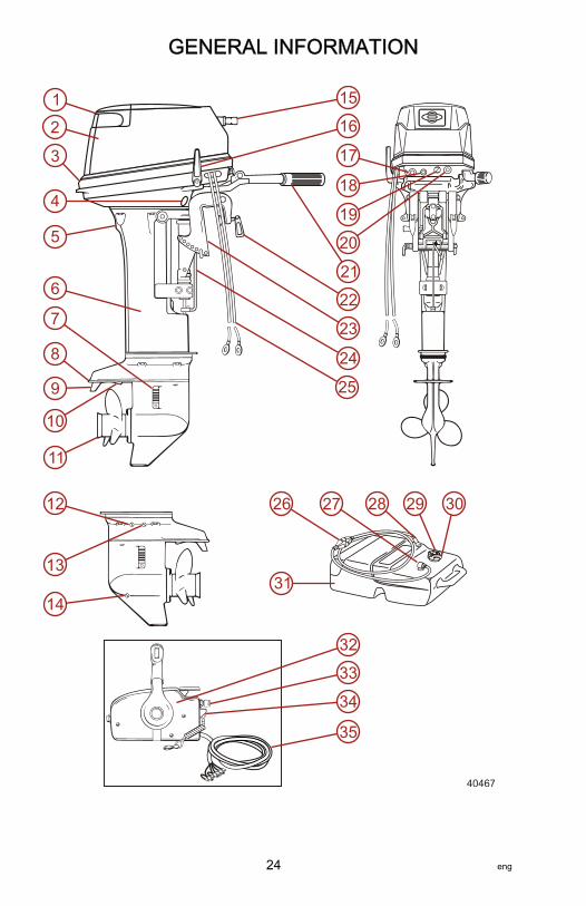
E Models1 - Tilt handle2 - Top cowl3 - Bottom cowl4 - Reverse lock lever5 - Water pump indicator hole6 - Driveshaft housing7 - Water strainer8 - Anti‑ventilation plate9 - Anode/trim tab10 - Secondary water intake11 - Propeller12 - Oil drain plug (upper)13 - Water plug14 - Oil drain plug (lower)15 - Starter handle16 - Shift lever17 - Stop switch (optional)
18 - Starter switch button19 - Choke knob20 - Fuel hose connector21 - Throttle grip22 - Clamp screws23 - Transom brackets24 - Thrust rod25 - Battery cables26 - Primer bulb27 - Fuel pickup elbow28 - Fuel connector29 - Fuel tank cap30 - Air vent screw31 - Fuel tank32 - Remote control box33 - Main switch34 - Lanyard stop switch35 - Harness assembly
Associated Parts
Name Qty. Dimensions
Service tools
Tool bag 1Pliers 1Socket wrench 1 10 x 13 mmSocket wrench 1 21 mmSocket wrenchhandle 1
Screwdriver 1Screwdriver handle 1
Spare parts
Starter rope 1 1000 mm
Spark plug 1NGK B7HS‑10 orChampion L82C(gap: 1.0 mm)
Cotter pin 1
Other*
Fuel tank 1Primer bulb 1 setRemote control box 1 set E Models onlyRemote controlattachment 1 set E Models only
* Not included as standard accessories in some markets.
GENERAL INFORMATION
eng 25

Removing the Motor1. Stop the engine.2. Disconnect the fuel connector, the remote control cable, the battery
cables, bracket fixing bolts and nuts, etc. from the motor.3. Remove the motor from the hull and completely drain the water from the
gear housing. Be sure to keep the engine higher than the propellerwhenever you carry the motor.
Carrying the MotorBe sure to keep the motor in a vertical position whenever you carry the motor.
39485
NOTE: If you carry the motor in a horizontal position, keep the powerheadhigher than the propeller.IMPORTANT: Beware of explosion danger. Spilled and vapored gasoline mayeasily catch fire and explode. Be sure to fully discharge gasoline from thecarburetors when transporting the engine. Wipe off spilled gasoline with a rag.
Storing the MotorKeep the motor in a vertical position whenever you store the motor.NOTE: If you store the motor in a horizontal position, lay the motor down on theground with the handles facing upward.
40803
TRANSPORTING
26 eng

Trailering Boat/OutboardThe boat should be trailered with the outboard tilted down in a vertical (normalrunning) position, fully down.NOTE: Trailering in the tilted position may cause damage to the motor, boat,etc. If trailering with the motor fully down is not available (the gearcase skeg istoo close to the road in a vertical position), secure the motor using a device likea transom saver bar in the tilted position.
39486
Shift the outboard to the forward gear. This prevents the propeller fromspinning freely.If additional ground clearance is required, the outboard should be tilted upusing an accessory outboard support device. Refer to your local dealer forrecommendations. Additional clearance may be required for railroad crossings,driveways, and trailer bouncing.IMPORTANT: The tilt lock and shallow water drive feature (tiller handle models)on the outboard are not intended to support the outboard in the tilted positionwhen trailering.
TRANSPORTING
eng 27

Transporting Portable Fuel Tanks
! WARNINGAvoid serious injury or death from a gasoline fire or explosion. Follow thetransporting instructions supplied with the portable fuel tank. Transport thefuel tank in a well ventilated area away from open flame or sparks.
MANUAL VENTING TYPE FUEL TANKClose the fuel tank air vent when transporting tank. This will prevent escape offuel or vapors from tank.
26793
AUTO-VENTING TYPE FUEL TANK1. Disconnect the remote fuel line from tank. This will close the air vent and
prevent escape of fuel or vapors from tank.2. Install tether cap over the fuel line connector stem. This will protect the
connector stem from being accidentally pushed‑in, allowing fuel or vaporto escape.
a - Connector stemb - Tether cap
F
a
b 26794
TRANSPORTING
28 eng

Fuel RequirementsIMPORTANT: Use of improper gasoline can damage your engine. Enginedamage resulting from the use of improper gasoline is considered misuseof the engine and will not be covered under the limited warranty.
FUEL RATINGSMercury outboard engines will operate satisfactorily with any major brand ofunleaded gasoline that meets the following specifications:USA and Canada ‑ A posted pump octane rating of 87 (R+M)/2, minimum, formost models. Premium gasoline 91 (R+M)/2 octane is also acceptable for mostmodels. Do not use leaded gasoline.Outside USA and Canada ‑ A posted pump octane rating of 91 RON,minimum, for most models. Premium gasoline (95 RON) is also acceptable forall models. Do not use leaded gasoline.
USING REFORMULATED (OXYGENATED) GASOLINE (USA ONLY)Reformulated gasoline is required in certain areas of the USA and isacceptable for use in your Mercury Marine engine. The only oxygenatecurrently in use in the USA is alcohol (ethanol, methanol, or butanol).
GASOLINE CONTAINING ALCOHOL
Bu16 Butanol Fuel BlendsFuel blends of up to 16.1% butanol (Bu16) that meet the published MercuryMarine fuel rating requirements are an acceptable substitute for unleadedgasoline. Contact your boat manufacturer for specific recommendations onyour boat's fuel system components (fuel tanks, fuel lines, and fittings).
Methanol and Ethanol Fuel BlendsIMPORTANT: The fuel system components on your Mercury Marine engine willwithstand up to 10% alcohol (methanol or ethanol) content in the gasoline. Yourboat's fuel system may not be capable of withstanding the same percentage ofalcohol. Contact your boat manufacturer for specific recommendations on yourboat's fuel system components (fuel tanks, fuel lines, and fittings).Be aware that gasoline containing methanol or ethanol may cause increased:• Corrosion of metal parts• Deterioration of rubber or plastic parts• Fuel permeation through the rubber fuel lines• Likelihood of phase separation (water and alcohol separating from the
gasoline in the fuel tank)
FUEL AND OIL
eng 29

! WARNINGFuel leakage is a fire or explosion hazard, which can cause serious injury ordeath. Periodically inspect all fuel system components for leaks, softening,hardening, swelling, or corrosion, particularly after storage. Any sign ofleakage or deterioration requires replacement before further engineoperation.
IMPORTANT: If you use gasoline that contains or might contain methanol orethanol, you must increase the frequency of inspection for leaks andabnormalities.IMPORTANT: When operating a Mercury Marine engine on gasoline containingmethanol or ethanol, do not store the gasoline in the fuel tank for long periods.Cars normally consume these blended fuels before they can absorb enoughmoisture to cause trouble; boats often sit idle long enough for phase separationto take place. Internal corrosion may occur during storage if alcohol haswashed protective oil films from internal components.
Oil Recommendation
Recommended Oil Mercury or Quicksilver Premium 2‑Cycle TC‑W3Outboard Oil
IMPORTANT: Oil must be NMMA certified TC‑W3 2‑Cycle oil.Mercury or Quicksilver Premium TC‑W3 2‑Cycle oil is recommended for thisengine. For added protection and lubrication, Mercury or Quicksilver PremiumPlus TC‑W3 2‑Cycle oil is recommended. If Mercury or Quicksilver outboard oilis not available, substitute another brand of 2‑cycle outboard oil that is NMMACertified TC‑W3. Severe engine damage may result from use of an inferior oil.
Mixing Fuel and OilUse a 1:25 oil/gasoline mixture in the first tank of fuel.After the break‑in fuel mixture is used up, use a 1:50 oil/gasoline mixture. Referto the table (following) for mixing ratios.
OIL/GASOLINE MIXING RATIO CHART
GASOLINE/OIL MIXING RATIO CHART
Oil/Gas Ratio 3.8 liters(1 US gal) gas
11.5 liters(3 US gal) gas
23 liters(6 US gal) gas
1:25 148 ml (5 fl oz) oil 473 ml (16 fl oz)oil
946 ml (32 fl oz)oil
1:50 89 ml (3 fl oz) oil 237 ml (8 fl oz) oil 473 ml (16 fl oz)oil
FUEL AND OIL
30 eng

MIXING PROCEDUREPour the full amount of oil, along with one gallon of gasoline, into an approvedcontainer. Shake the two together until they are thoroughly mixed. Add theremainder of gasoline and shake container to ensure mixing.
Engine Break‑InENGINE BREAK-IN FUEL MIXTUREUse a 1:25 oil/gasoline mixture in the first tank of fuel.
ENGINE BREAK-IN PROCEDURERefer to Operation ‑ Engine Break‑In Procedure for correct break‑inprocedure.
Filling Fuel Tank
! WARNINGAvoid serious injury or death from a gasoline fire or explosion. Use cautionwhen filling fuel tanks. Always stop the engine and do not smoke or allowopen flames or sparks in the area while filling fuel tanks.
Fill fuel tanks outdoors away from heat, sparks, and open flames.Always stop engine before refilling tanks.Do not completely fill the fuel tanks. Leave approximately 10% of the tankvolume unfilled. Fuel will expand in volume as its temperature rises and canleak under pressure if the tank is completely filled.
FILLING FUEL TANKS PERMANENTLY INSTALLEDSlowly pour the correct amount of oil along with gasoline as the tank is beingfilled.
FILLING PORTABLE FUEL TANKSRemove the portable fuel tanks from the boat to refill them.Pour the full amount of oil, along with one gallon of gasoline, into the fuel tank.Mix thoroughly, then pour the remainder of gasoline into the tank.
PORTABLE FUEL TANK PLACEMENT IN THE BOATPlace the fuel tank in the boat so the vent is higher than the fuel level undernormal boat operating conditions.
FUEL AND OIL
eng 31

Remote Control FeaturesYour boat may be equipped with the remote control shown. If not, consult yourdealer for a description of the functions and operations of the remote control.
a - Remote control handleb - Throttle only leverc - Ignition key switchd - Lanyard stop switch
Tilt Up and Tilt DownBASIC TILTING OPERATIONThe tilt feature allows the operator to tilt the outboard to a higher tilt angle foroperation in shallow water, or tilt the outboard to the full up position.When running the outboard, keep the tilt lever in the release position. Thisallows the outboard to return to the running position if the outboard should hitan underwater obstacle and be lifted up.Moving the tilt lever to the tilt position will allow the outboard to lock into theshallow water drive position or the full up position.IMPORTANT: When tilting up or down, be careful not to place your handbetween the swivel bracket and the stern bracket. Be sure to tilt the outboarddown slowly.NOTE: Stop the engine before tilting up.1. Stop the engine.
37982
a
b
c
d
FEATURES AND CONTROLS
32 eng

2. With the shift lever in Neutral (N) or Forward (F), fully tilt the motor uptoward by holding the tilt handle provided at the rear of the upper motorcover.
27023
3. Tilt up: Push the reverse lock lever down until it stops. This is the tilt upposition.
4. Tilt the engine all the way up until it locks in place.
a - Reverse lock lever
5. Tilt down: Pull the reverse lock lever upward until it stops. This is the tiltdown position.
6. Lift the engine up slightly, and then allow gravity to lower it for you.
a - Tilt down positionb - Tilt up positionc - Reverse lock lever
37535
a
39484
a
b
c
FEATURES AND CONTROLS
eng 33

Shallow Water OperationIMPORTANT: When in shallow water operation, be careful not to place yourhand between the swivel bracket and the stern bracket. Be sure to tilt theoutboard down slowly.NOTE: Slow down to trolling speed, and shift to Neutral (N) before operating inshallow water.1. Stop the engine.2. Tilt up: Put the reverse lock lever in the tilt up position, and tilt up the
engine to put the engine in the shallow water running position.
a - Reverse lock lever
3. Tilt down: Pull the reverse lock lever in the tilt down position, slightly liftup the engine, then put it down.
a - Tilt down positionb - Tilt up positionc - Reverse lock lever
37535
a
39484
a
b
c
FEATURES AND CONTROLS
34 eng

NOTE: Please follow the instructions below:• Ensure that the water inlet is submerged at all times and that water is
continuously running out of the cooling water check port.• Be sure to run the engine slowly when using the shallow water drive.
Running at higher speed will result in lack of control and may damage theengine.
• Ensure the motor does not strike the bottom, especially when running inreverse. If the motor does strike the bottom while in reverse, the impact istransmitted to the transom, which could damage both the motor and theboat.
Trim Angle AdjustmentThe vertical operating angle of your outboard is adjusted by changing theposition of the tilt pin in the adjustment holes provided. Proper adjustmentallows the boat to achieve optimum performance, stability, and minimizesteering effort.The following instructions explain how to set the best angle of the boat.The tilt pin should be adjusted so the outboard is positioned to runperpendicular to the water when the boat is running at full speed. This allowsthe boat to be driven parallel to the water.Arrange passengers and load in the boat so the weight is distributed evenly.The trim angle is adjusted by setting the trim position pin in the correct trimposition.
TRIM POSITION ADJUSTMENTS• Correct trim: The trim angle is optimum when the boat is parallel to the
water surface while running.• Trim down: If the trim angle is excessive, the bow will rise out of the
water and the speed will decrease. Furthermore, the bow may sway or thebottom may slam the water while cruising. In this case, decrease the trimangle by setting the trim position pin in a lower position.
FEATURES AND CONTROLS
eng 35

• Trim up: If the trim angle is too small, the bow will enter the water, thespeed will decrease, and water may enter the boat. In this case, the trimangle should be increased by setting the trim position pin in a higherposition.
a - Correct trimb - Trim downc - Trim upd - Move pin to raise bow upe - Move pin to lower bow downf - Trim position pin
Steering Friction AdjustmentSteering friction can be adjusted according to your preference with the steeringco‑pilot.
! WARNINGInsufficient friction adjustment can cause serious injury or death due to lossof boat control. When setting the friction adjustment, maintain sufficientsteering friction to prevent the outboard from steering into a full turn if thetiller handle or steering wheel is released.
Adjust the steering co‑pilot to achieve desired steering friction.• Turn clockwise for more friction.
41064
f
b
c
a
d e
FEATURES AND CONTROLS
36 eng

• Turn counterclockwise for less friction.
a - Steering co‑pilot
NOTE: The steering adjustment bolt is used to adjust the sliding friction of thesteering, but not to correct the steering. If excess tightening is given to the bolt,it may cause damage to the swivel bracket.
Throttle Grip Turning Friction AdjustmentTurn the friction adjustment screw to set and maintain the throttle at desiredspeed. Turn screw clockwise to tighten friction and turn screw counterclockwiseto loosen friction.
a - Tighten frictionb - Loosen frictionc - Throttle adjustment screw
Trim Tab AdjustmentPropeller steering torque will cause the boat to pull in one direction. Thissteering torque is a normal result from the outboard not trimmed with thepropeller shaft parallel to the water surface. The trim tab can help compensatefor this steering torque in many cases and can be adjusted within limits toreduce any unequal steering effort.• Operate the boat at normal cruising speed with the outboard set at the
desired operating angle position. Turn the boat left and right and note thedirection the boat turns more easily.
40867
a
41034
cb
a
FEATURES AND CONTROLS
eng 37

• If adjustment is necessary, loosen the trim tab bolt and make smalladjustments at a time.
• After the adjustment, securely tighten the trim tab bolt.NOTE: Check for looseness of the bolt and the trim tab at regular intervals. Dueto corrosion, the trim tab will wear down over time.The trim tab is located under the anti‑ventilation plate.• If the boat steers toward the left, set the trim tab in the direction of B.• If the boat steers toward the right, set the trim tab in the direction of C.
a - Trim tabb - Steers toward the left, set the trim tab in the direction of Bc - Steers toward the right, set the trim tab in the direction of Cd - Turning lefte - Turning right
IMPORTANT: The trim tab also acts as an anode to prevent galvanic corrosion.Do not apply any paint, grease, or other material to the surface of the trim tab.NOTE: Trim tab adjustment will have little effect reducing steering torque if theoutboard is installed with the anti‑ventilation plate approximately 50 mm (2 in.)or more above the boat bottom.
37494
a
b
c
d e
FEATURES AND CONTROLS
38 eng

REMOTE CONTROL LEVER FRICTION (THROTTLE FRICTIONADJUSTMENT SCREW)To adjust the friction of the remote control lever, turn the throttle frictionadjustment screw on the front of the remote control box. Turn clockwise toincrease the friction and counterclockwise to decrease it.
a - Turn counterclockwise todecrease the friction
b - Turn clockwise to increase thefriction
c - Throttle friction adjustmentscrew38385
ab
c
FEATURES AND CONTROLS
eng 39

Prestarting Check List• Operator knows safe navigation, boating, and operating procedures.• An approved personal flotation device of suitable size for each person
aboard and readily accessible (it is the law).• A ring type life buoy or buoyant cushion designed to be thrown to a
person in the water.• Know your boats' maximum load capacity. Look at the boat capacity plate.• Fuel supply OK.• Arrange passengers and load in the boat so the weight is distributed
evenly and everyone is seated in a proper seat.• Tell someone where you are going and when you expect to return.• It is illegal to operate a boat while under the influence of alcohol or drugs.• Know the waters and area you will be boating; tides, currents, sand bars,
rocks, and other hazards.• Make inspection checks listed in Maintenance ‑ Inspection and
Maintenance Schedule.
Operating in Freezing TemperaturesWhen using your outboard or having your outboard moored in freezing or nearfreezing temperatures, keep the outboard tilted down at all times so thegearcase is submerged. This prevents the trapped water in the gearcase fromfreezing and causing possible damage to the water pump and othercomponents.If there is a chance of ice forming on the water, the outboard should beremoved and drained completely of water. If ice should form at the water levelinside the outboard driveshaft housing, it will block water flow to the enginecausing possible damage.
Operating in Saltwater or Polluted WaterWe recommend that you flush the internal water passages of your outboardwith fresh water after each use in salt or polluted water. This will prevent abuildup of deposits from clogging the water passages. Refer to Maintenance ‑Flushing the Cooling System.If you keep your boat moored in the water, always tilt the outboard so thegearcase is completely out of water (except in freezing temperatures) when notin use.Wash the outboard exterior and flush out the exhaust outlet of the propeller andgearcase with fresh water after each use. Each month, spray Mercury Precisionor Quicksilver Corrosion Guard on external metal surfaces. Do not spray oncorrosion control anodes as this will reduce the effectiveness of the anodes.
OPERATION
40 eng

Operating at High ElevationsIMPORTANT: To prevent serious damage to the engine caused by a lean fuelmixture, do not operate your outboard (if the jets were changed for highelevation) at a lower elevation unless the jets are changed again to correspondto the new elevation.Operating your outboard at an elevation higher than 750 m (2500 ft.) above sealevel may require a carburetor jet change and/or different pitch propeller.Consult your dealer. This will reduce the normal performance loss experiencedas a result of reduced oxygen in the air causing an overly rich fuel mixture.
Operating Outboard as an Auxiliary EngineIf the outboard is used as an auxiliary engine, stop the engine and tilt theoutboard out of the water when using the main power source.IMPORTANT: The outboard must be restrained from bouncing while operatingthe boat using the main power source. Bouncing can damage the outboard andboat transom.
Prestarting Instructions1. Attach the fuel connector to the engine connector. The arrow‑mark on the
primer bulb should be facing the engine.
41508
NOTICEWithout sufficient cooling water, the engine, the water pump, and othercomponents will overheat and suffer damage. Provide a sufficient supply ofwater to the water inlets during operation.
OPERATION
eng 41

2. Loosen the air vent screw on the tank cap.
37518
3. Feed fuel to the carburetor by squeezing the primer bulb until it is firm.
a - To fuel tankb - To enginec - Fuel flow direction
4. Make sure the cooling water intake is submerged.
43116
Engine Break‑In ProcedureIMPORTANT: Failure to follow the engine break‑in procedures can result inpoor performance throughout the life of the engine and can cause enginedamage. Always follow break‑in procedures.
ENGINE OILUse Mercury or Quicksilver engine oil or the other recommended oil (TC‑W3).
37714
a
c
b
OPERATION
42 eng

NOTE: Do not mix different brands of oil. The mixing of different brands, ordifferent kinds even if the same brand, may cause gelling, resulting in blockageof filter screens. This may lead to serious engine damage due to the lack oflubrication.Mixing ratio (1:50): Mercury or Quicksilver engine oil or recommended engineoil (TC‑W3), 1:Unleaded gasoline 50.
ENGINE BREAK-IN FUEL MIXTUREUse a 1:25 oil/gasoline mixture in the first tank of fuel. Use Mercury orQuicksilver engine oil or the recommended oil (TC‑W3).
BREAK-INBreak‑in period for 10 hoursVary the throttle setting during the first hour of operation.During the first hour of operation, avoid remaining at a constant speed for morethan two minutes and avoid sustained wide‑open throttle.
Time 0–9 min. 10–59min.
1:00–1:59hrs.
2:00–9:59hrs. 10 hrs.
Method ofoperation
Idling ortrolling
Throttleopenless than½ of theway(about3000RPM)
Throttle openless than 3/4of the way(about 4000RPM)
Throttle open3/4 of theway (about4000 RPM)
Normaloperating
Conditions
Cruising atno morethanminimumspeed
A full‑throttlerun is allowedfor 1 min.every 10 min.
A full‑throttlerun isallowed for 2min. every 10min.
Warming Up the EngineWarm the engine at low engine speeds for about three minutes. This allows thelubrication oil to circulate to all parts of the engine. Operating the enginewithout allowing it to warm up, shortens the engine life. Be sure to check thatwater is coming out of the water pump indicator when warming up the engine.
OPERATION
eng 43

NOTE: If the engine is operated continuously without water discharging fromthe water pump indicator or idle hole, the engine may overheat.
a - Water pump indicatorb - Idle hole
Engine speeds: Idling speed after warming up.
In gear In Neutral800 RPM 950 RPM
Starting the EngineBefore starting, read the Pre‑Starting Check List, special operatinginstructions, and Engine Break‑in Procedure in the Operation section.Electric starting outboard models must not be started manually using thestarter rope, or run, without having the battery leads connected to abattery. Damage to the charging system could result.IMPORTANT: If no water is coming out of the water pump indicator hole, stopengine and check cooling water intake for obstruction. No obstruction mayindicate a water pump failure or blockage in the cooling system. Theseconditions will cause the engine to overheat. Have the outboard checked byyour dealer. Operating the engine while overheated will cause serious enginedamage.1. MH and EH Models: Place the shift lever in the Neutral (N) position.
38347
NOTE: Be sure that the shift lever is in Neutral (N) when starting the engine.This model is provided with a function that prevents starting in gear.
40472
a
b
OPERATION
44 eng

IMPORTANT: If the motor somehow does start in gear, do not use it. Contactyour authorized dealer.2. Turn the throttle grip until the mark on the grip faces the triangular mark
on the steering handle.
28847
3. Pull the choke knob out all the way. The choke operation is not necessarywhen the engine is warm.
38349
4. MH models: Pull the starter handle slowly until you feel resistance. Thenpull it quickly.
a - Pull slowlyb - Pull quickly
37523
a b
OPERATION
eng 45

5. EH Models: Push the starter switch button.
a - Starter switch button
6. Release the button when the engine has started.IMPORTANT: If the choke knob was used for the engine start, push it backwhen the engine has started.7. E Models: Insert the main switch key.8. Set the control lever in the Neutral (N) position. Raise the Neutral (N)
warm‑up lever.
a - Fully openedb - Fully closedc - Neutral warm‑up leverd - Ignition keye - Lanyard stop switch
9. Turn the main switch key to the start position. Then, continuously pushthe key to operate the choke.
39481
a
37715
N
c
de
a
b
OPERATION
46 eng

NOTE: Choke operation is not necessary if the engine is warm.
a - Offb - Onc - Push to operate choke
10. Stop pushing the key when the engine has started. The key returns to theoriginal position automatically.
NOTE: The neutral warm‑up lever cannot be raised when the control levershift is in Forward (F) or Reverse (R).NOTE: E and EH Models:• Continuous operation of the starter motor can shorten the life of the
battery and the starter motor. Operate the starter motor for a maximum ofthree seconds. If the engine does not start, wait five seconds beforeengaging the starter motor again.
• Do not engage the starter motor after the engine has started.
Gear ShiftingIMPORTANT: Observe the following:• Never shift the outboard into gear unless the engine speed is at idle.
Do not shift the outboard into reverse when the engine is notrunning.
MH and EH Models1. Forward: Turn the throttle grip to reduce the engine speed. When the
engine reaches trolling speed, quickly pull the shift lever to the Forward(F) position.
37466
ab
c
OPERATION
eng 47

2. Reverse: As when shifting to Forward (F), reduce the engine speed,when the engine reaches trolling speed, quickly push the shift lever toReverse (R) position.
a - Reverse (R)b - Forward (F)
E Models1. Forward: Quickly push the control lever to the Forward (F) position at
32°, where the gear is connected, while lifting up on the lock buttonlocated at the bottom of the control lever grip. Further shifting will openthe throttle.
2. Reverse: Quickly pull the control lever to the Reverse (R) position at 32°,where the gear is connected, while lifting up on the lock button located atthe bottom of the control lever grip. Further shifting will open the throttle.
NOTE: The control lever is inoperative unless the neutral warm‑up lever is inthe fully closed position.
37713
a b
OPERATION
48 eng

NOTE: Do not increase the engine speed unnecessarily when operating theneutral warm‑up lever.
a - Fully openb - Throttlec - Forward (F)d - Shifte - Neutral (N)f - Reverse (R)g - Fully closedh - Neutral warm‑up leveri - Lock button
Stopping the EngineMH and EH Models1. Turn the throttle grip to the low speed position.2. Put the shift lever into the Neutral (N) position. Run the engine for 2–3
minutes at idling speed if it has been running at full speed.
39483
a
bg
d d
g
fc
ah
i
e
OPERATION
eng 49

3. Push the stop switch to stop the engine.
37877
E Models1. Put the shift lever into the Neutral (N) position and run the engine for 2–3
minutes at idling speed.
37882
N
OPERATION
50 eng
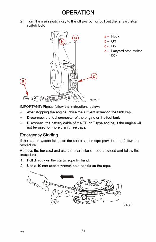
2. Turn the main switch key to the off position or pull out the lanyard stopswitch lock.
a - Hookb - Offc - Ond - Lanyard stop switch
lock
IMPORTANT: Please follow the instructions below:• After stopping the engine, close the air vent screw on the tank cap.• Disconnect the fuel connector of the engine or the fuel tank.• Disconnect the battery cable of the EH or E type engine, if the engine will
not be used for more than three days.
Emergency StartingIf the starter system fails, use the spare starter rope provided and follow theprocedure.Remove the top cowl and use the spare starter rope provided and follow theprocedure.1. Pull directly on the starter rope by hand.2. Use a 10 mm socket wrench as a handle on the rope.
38361
37716
a
bc
d
OPERATION
eng 51

! WARNINGHigh voltage is present any time the key is turned on, especially whenstarting or operating the engine. Do not touch ignition components or metaltest probes and stay clear of spark plug leads when performing live tests.
! WARNINGThe exposed moving flywheel can cause serious injury. Keep your hands,hair, clothing, tools, and other objects away from engine when starting orrunning the engine. Do not attempt to reinstall the flywheel cover or topcowl when engine is running.
OPERATION
52 eng
Outboard CareTo keep your outboard in the best operating condition, it is important that youroutboard receive the periodic inspections and maintenance listed in theInspection and Maintenance Schedule. We urge you to keep it maintainedproperly to ensure the safety of you and your passengers, and retain itsdependability.Record maintenance performed in the Maintenance Log at the back of thisbook. Save all maintenance work orders and receipts.
SELECTING REPLACEMENT PARTS FOR YOUR OUTBOARDWe recommend using original Mercury Precision or Quicksilver replacementparts and Genuine Lubricants.
Inspection and Maintenance ScheduleDAILY CHECKS• Check the engine oil level• Check the lanyard stop switch• Inspect the fuel system for leaks• Inspect the engine tightness on the transom• Check the steering system for binding• Check the propeller for damage• Inspect the hydraulic steering fittings and hoses for leaks or signs of
damage, if equipped• Check the hydraulic steering fluid level, if equipped
AFTER EACH USE• Wash the power package exterior with fresh water• Flush the outboard cooling system, saltwater or brackish water only
ANNUALLY OR 100 HOURS• Grease the engine, if applicable• Change the engine oil and filter, if equipped• Inspect the thermostat, saltwater or brackish water only• Add Quickleen to the fuel tank, once per year, per engine• Apply anti‑seize to the spark plug threads• Replace the gear lubricant• Inspect the corrosion control anodes• Replace all filters on the suction side of the fuel system—dealer item• Lubricate the driveshaft splines—dealer item• Lubricate the propeller shaft splines—dealer item• Check the tightness on all the fasteners—dealer item
MAINTENANCE
eng 53

• Check the torque of the outboard mounting hardware—dealer item• Check the battery condition and tightness of the battery cable connection
—dealer item
THREE YEARS OR 300 HOURS• Replace the spark plugs• Replace the water pump impeller—dealer item• Inspect the carbon fiber reeds—dealer item• Inspect the wire harness connectors—dealer item• Check the remote control cable adjustment, if applicable—dealer item• Replace the high‑pressure fuel filter—dealer item• Replace the accessory drive belt—dealer item• Check the power trim fluid level—dealer item• Inspect the engine motor mounts—dealer item
Flushing the Cooling SystemFlush the internal water passages of the outboard with fresh water after eachuse in salt, polluted, or muddy water. This will help prevent a buildup ofdeposits from clogging the internal water passages.Use a Mercury Precision or Quicksilver accessory (or equivalent) flushingattachment.IMPORTANT: The engine must be run during flushing in order to open thethermostat and circulate water through the water passages.
! WARNINGRotating propellers can cause serious injury or death. Never operate the boatout of the water with a propeller installed. Before installing or removing apropeller, place the drive unit in neutral and engage the lanyard stop switchto prevent the engine from starting. Place a block of wood between thepropeller blade and the anti‑ventilation plate.
1. Remove the propeller. Refer to Propeller Replacement. Install theflushing attachment so the rubber cups fit tightly over the cooling waterintake.
27256
MAINTENANCE
54 eng
Flushing Device 91‑44357Q 2
9192
Attaches to the water intakes; providesa fresh water connection when flushingthe cooling system or operating theengine.
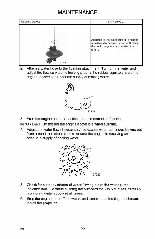
2. Attach a water hose to the flushing attachment. Turn on the water andadjust the flow so water is leaking around the rubber cups to ensure theengine receives an adequate supply of cooling water.
27259
3. Start the engine and run it at idle speed in neutral shift position.IMPORTANT: Do not run the engine above idle when flushing.4. Adjust the water flow (if necessary) so excess water continues leaking out
from around the rubber cups to ensure the engine is receiving anadequate supply of cooling water.
27260
5. Check for a steady stream of water flowing out of the water pumpindicator hole. Continue flushing the outboard for 3 to 5 minutes, carefullymonitoring water supply at all times.
6. Stop the engine, turn off the water, and remove the flushing attachment.Install the propeller.
MAINTENANCE
eng 55

Top Cowl Removal and InstallationREMOVAL1. Unlock the rear latch by pushing lever down.
29054
2. Lift rear of cowl and disengage front hook.
26851
INSTALLATION1. Engage the front hook and push cowl back over the cowl seal.2. Push cowl down and move the rear latch lever up to lock.
Battery InspectionThe battery should be inspected at periodic intervals to ensure proper enginestarting capability.IMPORTANT: Read the safety and maintenance instructions which accompanyyour battery.1. Turn off the engine before servicing the battery.2. Ensure the battery is secure against movement.3. Battery cable terminals should be clean, tight, and correctly installed.
Positive to positive and negative to negative.4. Ensure the battery is equipped with a nonconductive shield to prevent
accidental shorting of battery terminals.
MAINTENANCE
56 eng

Fuel System
! WARNINGFuel is flammable and explosive. Ensure that the key switch is off and thelanyard is positioned so that the engine cannot start. Do not smoke or allowsources of spark or open flame in the area while servicing. Keep the workarea well ventilated and avoid prolonged exposure to vapors. Always checkfor leaks before attempting to start the engine, and wipe up any spilled fuelimmediately.
Before servicing any part of the fuel system, stop the engine and disconnectthe battery. Drain the fuel system completely. Use an approved container tocollect and store fuel. Wipe up any spillage immediately. Material used tocontain spillage must be disposed of in an approved receptacle. Any fuelsystem service must be performed in a well‑ventilated area. Inspect anycompleted service work for sign of fuel leakage.
FUEL LINE INSPECTIONVisually inspect the fuel line and primer bulb for cracks, swelling, leaks,hardness, or other signs of deterioration or damage. If any of these conditionsare found, the fuel line or primer bulb must be replaced.
ENGINE FUEL FILTERInspect the sight bowl for water accumulation and inspect the filter element forsediment. Clean the filter as follows.
Cleaning the fuel filters and the fuel tankFuel filters are provided inside the fuel tank and engine.1. Fuel tank filter: Loosen the fuel pickup elbow shown, remove it and clean
the fuel filter.
a - Filterb - Fuel pickup elbow
37711
b
a
MAINTENANCE
eng 57

2. Engine filter: Remove cap, then clean the fuel filter in the engine.
a - Carburetorb - Fuel filter
3. Fuel tank: Water or dirt in the fuel tank may cause engine trouble. Cleanthe tank at specified times or after the motor has been stored for a longperiod (over three months).
IMPORTANT: Visually inspect for fuel leakage from the filter by squeezing theprimer bulb until firm, forcing fuel into the filter.
Exterior CareYour outboard is protected with a durable baked enamel finish. Clean and waxoften using marine cleaners and waxes.
Fuse Replacement ‑ Electric Start Remote Control ModelsIMPORTANT: Always carry spare SFE 20 amp fuses.
40475
a b
MAINTENANCE
58 eng

The electric starting circuit is protected from overload by an SFE 20 amp fuse.If the fuse is blown, the electric starter motor will not operate. Try to locate andcorrect the cause of the overload. If the cause is not found, the fuse may blowagain. Replace fuse with a fuse of the same rating.
3036
Replacing the AnodesThe outboard has a corrosion control anode installed on the gearcase. Ananode helps protect the outboard against galvanic corrosion by sacrificing itsmetal to be slowly eroded instead of the outboard metals.Two anodes are fitted at the gearcase and the mount bracket. When theanodes has been eroded more than 2/3, replace it immediately.
a - Anode/trim tab
IMPORTANT: Please follow the instructions below:1. Never grease or paint the anode.2. At each inspection, retighten the anode attaching bolt, as it is likely to be
subjected to electrolytic corrosion.
37879
a
MAINTENANCE
eng 59

Propeller Replacement
! WARNINGRotating propellers can cause serious injury or death. Never operate the boatout of the water with a propeller installed. Before installing or removing apropeller, place the drive unit in neutral and engage the lanyard stop switchto prevent the engine from starting. Place a block of wood between thepropeller blade and the anti‑ventilation plate.
1. Shift outboard to Neutral (N) position.
38347
2. Remove the spark plug leads to prevent the engine from starting.
26899
3. Place a block of wood between the gearcase and the propeller to hold thepropeller and remove the propeller nut.
27296
MAINTENANCE
60 eng

4. Remove the propeller from the shaft. If the propeller is seized to the shaftand cannot be removed, have the propeller removed by an authorizeddealer.
a - Cotter pinb - Nutc - Washerd - Propellere - Thrust hub
5. Coat the propeller shaft with Mercury Extreme Grease or 2‑4‑C withPTFE.
27305
Tube RefNo. Description Where Used Part No.
Extreme Grease Propeller shaft 8M0071842
95 2-4-C with PTFE Propeller shaft 92-802859A 1
IMPORTANT: To prevent the propeller hub from corroding and seizing to thepropeller shaft (especially in saltwater), always apply a coat of therecommended lubricant to the entire propeller shaft at the recommendedmaintenance intervals, and also each time the propeller is removed.
38055
a c
d e
b
MAINTENANCE
eng 61

6. Install forward thrust hub, propeller, washer, nut, and cotter pin onto thepropeller shaft.
a - Cotter pinb - Nutc - Washerd - Propellere - Forward thrust hubf - Propeller shaft
7. Place a block of wood between the gearcase and propeller and tightenthe propeller nut.
27341
8. Install the spark plug leads.
37520
a b c d e f
MAINTENANCE
62 eng

Spark Plug Inspection and Replacement
! WARNINGDamaged spark plug boots may emit sparks that can ignite fuel vapors underthe engine cowl, resulting in serious injury or death from a fire or explosion.To avoid damaging the spark plug boots, do not use any sharp object ormetal tool to remove the spark plug boots.
1. Remove the spark plug leads. Twist the rubber boots slightly and pull off.
26899
2. Remove the spark plugs to inspect. Replace the spark plug if theelectrode is worn or the insulator is rough, cracked, broken, blistered, orfouled.
26946
3. Set the spark plug gap (0.9–1.0 mm).
26947
Spark PlugNGK B7HS‑10 or BPR7HS‑10 or recommended ones (Champion L82 or RL82C with 1.0 mm gap)
4. Before installing spark plugs, clean off any dirt on the spark plug seats.Install plugs finger‑tight, then tighten 1/4 turn or torque to specifications.
MAINTENANCE
eng 63

Description Nm lb‑in. lb‑ftSpark plug 27 20
Lubrication PointsOnly let an authorized Mercury dealer perform service or maintenance on thisproduct. Be sure to use genuine parts, genuine lubricants, or recommendedlubricants.
Changing Gear Oil1. Place the outboard in a vertical operating position.2. Place a drain pan below the outboard.3. Remove the oil plugs (upper and lower) and drain the gear oil completely.
a - Upper oil drain plugb - Lower oil drain plugc - Water strainer
4. Insert the oil tube nozzle into the lower oil drain plug hole and fill with gearoil by squeezing the oil tube until oil flows out of the upper plug hole.
a - Upper oil drain plugb - Lower oil drain plugc - Water strainer
5. Install the upper oil drain plug, then remove the oil tube nozzle and installthe lower oil drain plug.
40473
b
a
c
40474
b
a
c
MAINTENANCE
64 eng

IMPORTANT: Use Mercury/Quicksilver gear oil or the recommended one (APLGL‑5: SAE #80–#90). Required volume: 370 ml (0.10 US gal).
Submerged OutboardA submerged outboard will require service within a few hours by an authorizeddealer once the outboard is recovered from the water. This immediate attentionby a servicing dealer is necessary once the engine is exposed to theatmosphere to minimize internal corrosion damage to the engine.
MAINTENANCE
eng 65

Preseason Check1. Check the electrolyte level, and measure the voltage and specific gravity
of the battery.
Specific Gravity at 20 °C Terminal Voltage (V) Charge Condition1.120 10.5 Fully discharged1.160 11.1 1/4 charged1.210 11.7 1/2 charged1.250 12.0 3/4 charged1.280 13.2 Fully charged
2. Check that the battery is secure and the battery cables are properlyinstalled.
3. Check that the shift and throttle function properly. Be sure to turn thepropeller shaft when checking the shift function or else the shift linkagemay be damaged.
Storage PreparationThe major consideration in preparing your outboard for storage is to protect itfrom rust, corrosion, and damage caused by freezing of trapped water.The following storage procedures should be followed to prepare your outboardfor out of season storage or prolonged storage (two months or longer).
NOTICEWithout sufficient cooling water, the engine, the water pump, and othercomponents will overheat and suffer damage. Provide a sufficient supply ofwater to the water inlets during operation.
FUEL SYSTEMIMPORTANT: Gasoline containing alcohol (ethanol or methanol) can cause aformation of acid during storage and can damage the fuel system. If thegasoline being used contains alcohol, it is advisable to drain as much of theremaining gasoline as possible from the fuel tank, remote fuel line, and enginefuel system.Fill the fuel tank and engine fuel system with treated (stabilized) fuel to helpprevent formation of varnish and gum. Proceed with the following instructions.• Portable fuel tank ‑ Pour the required amount of gasoline stabilizer (follow
instructions on container) into the fuel tank. Tip fuel tank back and forth tomix stabilizer with the fuel.
• Permanently installed fuel tank ‑ Pour the required amount of gasolinestabilizer (follow instructions on container) into a separate container andmix with approximately 1 liter (1 U.S. qt) of gasoline. Pour this mixture intothe fuel tank.
STORAGE
66 eng

• Place the outboard in water or connect flushing attachment for circulatingcooling water. Run the engine at idle RPM for ten minutes to fill theengine fuel system with stabilized fuel.
Protecting External Outboard Components• Lubricate all outboard components listed in Maintenance ‑ Inspection
and Maintenance Schedule.• Touch up any paint nicks. See your dealer for touch‑up paint.• Spray Quicksilver or Mercury Precision Lubricants Corrosion Guard on
external metal surfaces (except corrosion control anodes).
Tube RefNo. Description Where Used Part No.
120 Corrosion Guard External metal surfaces 92-802878 55
Protecting Internal Engine ComponentsNOTE: Make sure the fuel system has been prepared for storage. Refer to FuelSystem, preceding.IMPORTANT: Refer to Maintenance ‑ Spark Plug Inspection and Replacementfor correct procedure for removing spark plug boots.• Place the outboard in water or connect flushing attachment for circulating
cooling water. Start the engine and let it run in neutral to warm up.• With engine running at fast idle, stop the fuel flow by disconnecting the
remote fuel line. When engine begins to stall, quickly spray Quicksilver orMercury Precision Lubricants Storage Seal into carburetor until enginestops from lack of fuel.
• Remove the spark plugs and inject a five second spray of storage sealaround the inside of the cylinder.
• Rotate the flywheel manually several times to distribute the storage sealin the cylinder. Reinstall spark plug.
Gearcase• Drain and refill the gearcase lubricant. Refer to Changing Gear Oil.
Positioning Outboard for StorageStore outboard in an upright (vertical) position to allow water to drain out of theoutboard.
NOTICEStoring the outboard in a tilted position can damage the outboard. Watertrapped in the cooling passages or rain water collected in the propellerexhaust outlet in the gearcase can freeze. Store the outboard in the full downposition.
STORAGE
eng 67

Battery Storage• Follow the battery manufacturer's instructions for storage and charging.• Remove the battery from the boat and check water level. Charge if
necessary.• Store the battery in a cool, dry place.• Periodically check the water level and charge the battery during storage.
STORAGE
68 eng

Starter Motor Will Not Crank the Engine (Electric Start Models)POSSIBLE CAUSES• Remote control models ‑ Blown 20 amp fuse in the starting circuit. Refer
to Maintenance section.• Outboard is not shifted to neutral position.• Weak battery or battery connections are loose or corroded.• Ignition key switch failure.• Wiring or electrical connection faulty.• Starter motor or starter solenoid failure.
Engine Will Not StartPOSSIBLE CAUSES• Lanyard stop switch not in "RUN" position.• Incorrect starting procedure. Refer to Operation section.• Old or contaminated gasoline.• Engine flooded. Refer to Operation section.• Fuel is not reaching the engine.
a. Fuel tank is empty.b. Fuel tank vent not open or restricted.c. Fuel line is disconnected or kinked.d. Primer bulb not squeezed.e. Primer bulb check valve is faulty.f. Fuel filter is obstructed. Refer to Maintenance section.g. Fuel pump failure.h. Fuel tank filter obstructed.
• Ignition system component failure.• Spark plugs fouled or defective. Refer to Maintenance section.
Engine Runs ErraticallyPOSSIBLE CAUSES• Spark plugs fouled or defective. Refer to Maintenance section.• Incorrect setup and adjustments.• Fuel is being restricted to the engine.
• Engine fuel filter is obstructed. Refer to Maintenance section.• Fuel tank filter obstructed.• Stuck anti‑siphon valve on built in fuel tank.• Fuel line is kinked or pinched.
• Fuel pump failure.
TROUBLESHOOTING
eng 69

• Ignition system component failure.
Performance LossPOSSIBLE CAUSES• Throttle not fully open.• Damaged or improper size propeller.• Incorrect engine timing, adjustments, or setup.• Boat overloaded or load improperly distributed.• Excessive water in bilge.• Boat bottom is dirty or damaged.
Battery Will Not Hold ChargePOSSIBLE CAUSES• Battery connections are loose or corroded.• Low electrolyte level in battery.• Worn out or inefficient battery.• Excessive use of electrical accessories.• Defective rectifier, alternator, or voltage regulator.
TROUBLESHOOTING
70 eng

Service AssistanceLOCAL REPAIR SERVICEIf you need service for your Mercury‑outboard‑powered boat, take it to yourauthorized dealer. Only authorized dealers specialize in Mercury products andhave factory‑trained mechanics, special tools and equipment, and genuineQuicksilver parts and accessories to properly service your engine.NOTE: Quicksilver parts and accessories are engineered and built by MercuryMarine specifically for your power package.
SERVICE AWAY FROM HOMEIf you are away from your local dealer and the need arises for service, contactthe nearest authorized dealer. If, for any reason, you cannot obtain service,contact the nearest Regional Service Center. Outside the United States andCanada, contact the nearest Marine Power International Service Center.
STOLEN POWER PACKAGEIf your power package is stolen, immediately advise the local authorities andMercury Marine of the model and serial numbers and to whom the recovery isto be reported. This information is maintained in a database at Mercury Marineto aid authorities and dealers in the recovery of stolen power packages.
ATTENTION REQUIRED AFTER SUBMERSION1. Before recovery, contact an authorized Mercury dealer.2. After recovery, immediate service by an authorized Mercury dealer is
required to reduce the possibility of serious engine damage.
REPLACEMENT SERVICE PARTS
! WARNINGAvoid fire or explosion hazard. Electrical, ignition, and fuel systemcomponents on Mercury Marine products comply with federal andinternational standards to minimize risk of fire or explosion. Do not usereplacement electrical or fuel system components that do not comply withthese standards. When servicing the electrical and fuel systems, properlyinstall and tighten all components.
Marine engines are expected to operate at or near full throttle for most of theirlives. They are also expected to operate in both fresh and saltwaterenvironments. These conditions require numerous special parts.
OWNER SERVICE ASSISTANCE
eng 71

PARTS AND ACCESSORIES INQUIRIESDirect any inquiries concerning Quicksilver replacement parts and accessoriesto your local authorized dealer. The dealer has the necessary information toorder parts and accessories for you if they are not in stock. Only authorizeddealers can purchase genuine Quicksilver parts and accessories from thefactory. Mercury Marine does not sell to unauthorized dealers or retailcustomers. When inquiring about parts and accessories, the dealer requires theengine model and serial numbers to order the correct parts.
RESOLVING A PROBLEMSatisfaction with your Mercury product is important to your dealer and to us. Ifyou ever have a problem, question or concern about your power package,contact your dealer or any authorized Mercury dealership. If you needadditional assistance:1. Talk with the dealership's sales manager or service manager. Contact the
owner of the dealership if the sales manager and service manager havebeen unable to resolve the problem.
2. If your question, concern, or problem cannot be resolved by yourdealership, please contact the Mercury Marine Service Office forassistance. Mercury Marine will work with you and your dealership toresolve all problems.
The following information will be needed by the Customer Service:• Your name and address• Your daytime telephone number• The model and serial numbers of your power package• The name and address of your dealership• The nature of the problem
CONTACT INFORMATION FOR MERCURY MARINE CUSTOMERSERVICEFor assistance, call, fax, or write to the geographic office in your area. Pleaseinclude your daytime telephone number with mail and fax correspondence.
United States, Canada
Telephone English +1 920 929 5040Français +1 905 636 4751
Mercury MarineW6250 Pioneer RoadP.O. Box 1939Fond du Lac, WI 54936-1939Fax English +1 920 929 5893
Français +1 905 636 1704Website www.mercurymarine.com
OWNER SERVICE ASSISTANCE
72 eng

Australia, PacificTelephone +61 3 9791 5822 Brunswick Asia Pacific Group
41–71 Bessemer DriveDandenong South, Victoria 3175Australia
Fax +61 3 9706 7228
Europe, Middle East, AfricaTelephone +32 87 32 32 11 Brunswick Marine Europe
Parc Industriel de Petit-RechainB-4800 Verviers,Belgium
Fax +32 87 31 19 65
Mexico, Central America, South America, CaribbeanTelephone +1 954 744 3500 Mercury Marine
11650 Interchange Circle NorthMiramar, FL 33025U.S.A.
Fax +1 954 744 3535
JapanTelephone +072 233 8888 Kisaka Co., Ltd.
4‑130 Kannabecho, Sakai‑kuSakai‑shi, Osaka 590‑0984, JapanFax +072 233 8833
Asia, SingaporeTelephone +65 65466160 Brunswick Asia Pacific Group
T/A Mercury Marine Singapore Pte Ltd29 Loyang DriveSingapore, 508944
Fax +65 65467789
Ordering LiteratureBefore ordering literature, have the following information about your powerpackage available:
Model Serial NumberHorsepower Year
UNITED STATES AND CANADAFor additional literature for your Mercury Marine power package, contact yournearest Mercury Marine dealer or contact:
OWNER SERVICE ASSISTANCE
eng 73

Mercury MarineTelephone Fax Mail
(920) 929‑5110(USA only)
(920) 929‑4894(USA only)
Mercury MarineAttn: Publications Department
P.O. Box 1939Fond du Lac, WI 54936-1939
OUTSIDE THE UNITED STATES AND CANADAContact your nearest Mercury Marine authorized service center to orderadditional literature that is available for your particular power package.
Submit the followingorder form with paymentto:
Mercury MarineAttn: Publications DepartmentW6250 Pioneer RoadP.O. Box 1939Fond du Lac, WI 54936-1939
Ship To: (Copy this form and print or type–This is your shipping label)NameAddressCity, State, ProvinceZIP or postal codeCountry
Quantity Item Stock Number Price Total. .. .. .. .. .
Total Due .
OWNER SERVICE ASSISTANCE
74 eng

Mercury Marine Validated Engine Mounting HardwareIMPORTANT: Mercury Marine provides validated fasteners and installationinstructions, including torque specifications, with all of our outboards so theycan be properly secured to boat transoms. Improper installation of the outboardcan cause performance and reliability issues that can lead to safety concerns.Follow all of the instructions relating to the outboard installation. DO NOTmount any other accessory onto the boat with the fasteners provided with theoutboard. For example, do not mount tow sport bars or boarding ladders ontothe boat using the mounting hardware included with the outboard. Installingother products onto the boat that utilize the outboard mounting hardware willcompromise the ability of that hardware to properly and safely secure theoutboard to the transom.Outboards that require validated mounting hardware will have the followingdecal on the transom clamp.
51965
Installing OutboardNOTE: If outboard is a remote control electric start model, follow instructions inthe outboard installation manual (provided with the outboard) for installingremote steering shift and throttle cables and remote wiring harness.
INSTALLING OUTBOARD ON TRANSOMIMPORTANT: Most boats are rated and certified in terms of their maximumhorsepower, and this is shown on the boat's certification plate. Do not equipyour boat with an outboard that exceeds this limit. If in doubt, contact yourdealer. Do not operate the engine unit until it has been securely mounted onthe boat in accordance with the instructions below.
INSTALLATION
eng 75

1. Single engine: Position the outboard motor at the center of the transom.Mount it using a cushioning pad or plate.
a - Boat transom
2. Twin engine: Position the outboard engines approximately 580 mm (22.8in.) apart, measured from the centerline of each engine, and equaldistance (a) from the center of the transom.
a - Equal distance from thecenter
3. Transom matching: Be sure that the anti‑ventilation plate of the outboardis below the water surface when running with the throttle wide open. If theabove condition cannot be met due to the shape of the bottom of the boat,please consult the dealer.
IMPORTANT: If the anti‑ventilation plate is at a level higher than the bottom ofthe boat, overheating may occur as a lack of cooling water flow in the coolingsystems.
37508
a
580 mm
37509
aa
INSTALLATION
76 eng

4. Clearance between the anti‑ventilation plate of the motor and the bottomof the boat must be 30–50 mm (1.2–2 in.). If the height difference exceeds50 mm (2 in.), engine power performance is likely to be reduced as aresult of increased water resistance to the gearcase assembly.
a - Bottom of hullb - Anti‑ventilation plate
5. Fasten the outboard by drilling two 7.9 mm (5/16 in.) holes through thetransom using transom clamp holes as a template. Fasten with two bolts,flat washers, and locknuts. The use of clamp bracket screws alone isinsufficient to properly and safely secure the outboard to the transom. Usea marine waterproofing sealer in holes and around bolts to make theinstallation water tight.
a - Clamp bracket screw
! WARNINGFailure to correctly fasten the outboard could result in the outboard propellingoff the boat transom resulting in property damage, serious injury, or death.Before operation, the outboard must be correctly installed with the requiredmounting hardware.
Installing the Remote Control DevicesIt is recommended to consult with your dealer for installation and adjustment ofthe remote control device.1. Installation of the remote control cables (box side): Follow the
instruction sheet provided with the remote control box.
30–50 mm (1.2” 2”)–
37510
a
b
42041a
INSTALLATION
eng 77

2. Installation of the remote control box: Follow the instruction sheetprovided with the remote control box.
37529
3. Installing of the remote control cable (engine side) and the harnessassembly (wiring harness).a. Fitting of throttle cable and shift cable guide:
• Throttle side: Attach the throttle cable adapter to the end of thecable and secure it with the nut.
a - Cable outer grooveb - Throttle cablec - Nutd - Springe - Throttle cable adapterf - Ball holder
40468
a b c d e f
INSTALLATION
78 eng

• Shift side: Attach the shift cable adapter to the end of the cableand secure it with the nut.
a - Cable outer grooveb - Shift cablec - Nutd - Shift cable adaptere - Lock pinf - Springg - Spring pin
b. Fitting of remote control cable to the engine:• Throttle side: Set the throttle cable to the cable clip and
connect the throttle cable adapter to the ball joint of theadvancer arm.
40469
a b c d efg
INSTALLATION
eng 79

• Shift side: Set the shift cable to the cable clip and insert thelock pin at the shift lever fitting hole and turn it 90° to lock it.
a - Cable of the shift sideb - Lock pinc - Springd - Shift cable adaptere - Spring pinf - Shift leverg - CDUh - Advancer armi - Ball jointj - Ball holderk - Throttle cable adapterl - Springm - Washern - Grommet is installed on the lower cowlo - Cable of the throttle sidep - Cable outer groove
40470
a
bc
de
fg
h
i
jkl
m
n
op
q
rs
t
u
INSTALLATION
80 eng

q - Cable clipr - Lower cowls - Clampt - Steering hook plateu - Shift cable clip
NOTE: Put the control lever in the Neutral (N) position and the neutralwarm‑up lever in the fully closed position.NOTE: Confirm whether the engine side shift is in gear when shifting thecontrol lever of the remote control box to its first position in Forward (F) orReverse (R), about 32°, and whether the throttle of the carburetor is fully openwhen shifting the lever further. Confirm whether the carburetor's throttle is fullyclosed when the control lever is shifted to the Neutral (N) position. If it is not,adjust the position of the ball holder.
c. Connecting Electrical Harnesses• Pass the cable assembly from the remote control box through
the hole in the lower cowl and connect the electric terminals.
INSTALLATION
eng 81

• Secure the cable assembly with the clamp according to thedrawing below.
a - Clampb - Starter solenoidc - Fuse wired - Choke solenoide - Rectifierf - From the remote control boxg - Battery cableh - Cable assembly
Wire Color Code Abbreviations
Wire Color AbbreviationsBLK Black
BLU BlueBRN Brown GRY GrayGRN Green ORN or ORG OrangePNK Pink PPL or PUR PurpleRED Red TAN TanWHT White YEL YellowLT or LIT Light DK or DRK Dark
40471
ab c
a
d
e
f
gha
INSTALLATION
82 eng

Battery InstallationMOUNTING BATTERYFollow the battery manufacturer's instructions carefully. Mount battery securelyto the hull in a place free from splashing water.NOTE: Electric starting outboards must have the battery cables connected to abattery whenever the engine is running, even if started manually, as damage tothe charging system could result.
BATTERY CONNECTIONSConnect a red cable to the positive (+) terminal first and a black cable to thenegative (–) terminal of the battery. Put a red cap on the positive terminal.When disconnecting battery cables, be sure to disconnect the black cable first,and then the red cable.Required battery rating: 12 V battery with a recommended capacity of 40 AH ormore.• Battery cables must be long enough to allow free steering.• Battery cables must be arranged and protected from damage during
steering.• With poor cable connections, the starter will fail to start.• Battery cable terminals should be clean, tight, and correctly installed.
Positive to positive and negative to negative.• Battery must be fully charged before running the motor.
a - Red cable (+)b - Black cable (–)
IMPORTANT: Please follow the instructions below:• Hydrogen gas is generated when charging a battery. Keep the battery in a
well‑ventilated area during charging. Remove the battery from the boat;this will protect your hull and interior from damage. Electric sparks,cigarette smoking, and other sources of fire must be avoided in thecharging area to prevent explosion of the battery.
• The battery fluid (electrolyte) contains sulfuric acid. If electrolyte is spilledon the skin or clothes, wash with plenty of water and consult a medicaldoctor. Always use safety glasses and rubber gloves when handling thebattery.
37712
a b
INSTALLATION
eng 83

Propeller SelectionThe propeller supplied with your outboard provides the best overallperformance under average operating conditions.A propeller must be selected so that the engine RPM when cruising with awide‑open throttle, is within the recommended range.
Model Wide‑open throttle RPM range9.9 4500–5300 RPM
15/18 5200–5800 RPM
If changing conditions cause the RPM to drop below the recommended range,such as warmer, more humid weather, operation at higher elevations,increased boat load, or a dirty boat bottom/gearcase, a propeller change orcleaning may be required to maintain performance and ensure the outboard'sdurability.Check full‑throttle RPM, using an accurate tachometer, with the engine trimmedout to a balanced‑steering condition (steering effort equal in both directions)without causing the propeller to break loose.
PROPELLER TABLEA propeller must be selected so that the engine RPM measured at wide‑openthrottle while cruising is within the recommended range. Refer to Accessories‑ Propeller Table of this manual.
INSTALLATION
84 eng

Propeller TableUse a Mercury/Quicksilver propeller.A propeller must be selected so that the engine RPM measured at wide‑openthrottle while cruising is within the recommended range: 9.9 HP = 4500–5300RPM; 15/18 HP = 5200–5800 RPM.Transom height: S = short, L = long, XL = extra long
Propeller Chart (Standard Equipment)Propeller size 235 x 203 mm (9.2 x 8 in.) 235 x 229 mm (9.2 x 9 in.)9.9 HP L, XL S15 HP L, XL S18 HP XL S, L
Propeller Chart
Propeller size 234 x 155 mm(9.2 x 6 in.)
234 x 254 mm(9.2 x 10 in.)
234 x 292 mm(9.2 x 11.5 in.)
9.9 HP Optional Optional Optional15 HP Optional Optional Optional18 HP Optional Optional Optional
ACCESSORIES
eng 85

AccessoriesOPTIONAL ACCESSORIES
40476
a b
cd
e
gh
f
ACCESSORIES
86 eng

a - Tachometer unit kitb - Tachometerc - Mercury/Quicksilver grease (250 g)d - Mercury/Quicksilver gear oil (500 ml)e - Touch‑up paintf - Mercury/Quicksilver engine oil (0.4 L, 1 L, 4 L, 20 L)g - Flushing attachmenth - Extension cord for light (lights are available on the market)
ACCESSORIES
eng 87

MH Models
39493
a b
c
d
e
f
g
hi
j
k
l
m
o
p
q
r
n
WIRING DIAGRAMS
88 eng

a - Remote control box (optional)b - Batteryc - Extension cord (optional)d - Fusee - Rectifierf - Extension cord for light (optional)g - Receptacle plug (optional)h - Lamp (12V 80W) [AC] (sold separately)i - Tachometer (optional)j - Tachometer, lead wire (optional)k - Separate cord, yellow (optional)l - Separate cord, white (optional)m - Flywheel magneton - Spark plugo - Ignition coilp - CD unitq - Lanyard stop switchr - Stop cord (optional)
WIRING DIAGRAMS
eng 89

EH Models
39494
a
bc
de
f
g
h
i
j
k
l
m
n
o
p q
WIRING DIAGRAMS
90 eng

a - Main switchb - Neutral switchc - Starter motord - Starter corde - Starter solenoidf - Fuseg - Rectifierh - Tachometeri - Tachometer lead wire (optional)j - Separate cord, yellow (optional)k - Separate cord, white (optional)l - Flywheel magnetom - Spark plugsn - Ignition coilo - CDUp - Lanyard stop switchq - 12V 40AH or 12V 70AH (sold separately)
WIRING DIAGRAMS
eng 91

E Models
39495
a
b
c
d
e
k
j
i
qh
g
f
l
m
n
o
p
tr
s
WIRING DIAGRAMS
92 eng

a - Harness assemblyb - 12V 40AH or 12V 70AH battery (sold separately)c - Tachometerd - Battery cable (+)e - Tachometer lead wire (optional)f - Fuse 15Ag - Starter solenoidh - Rectifieri - Flywheel magnetoj - Separate cord, white (optional)k - Separate cord, yellow (optional)l - Spark plugsm - Ignition coiln - CD unito - Lead wire, blackp - Lead wire, brownq - Starter motorr - Choke solenoids - Battery cablest - Lanyard stop switch (optional)
WIRING DIAGRAMS
eng 93

Single Remote Control Box
39496
a
b
cd
WIRING DIAGRAMS
94 eng

a - Neutral switchb - Main switchc - Stop switchd - Cord assembly
WIRING DIAGRAMS
eng 95

Maintenance LogRecord all maintenance performed on your outboard here. Be sure to save allwork orders and receipts.
Date Maintenance Performed Engine Hours
MAINTENANCE LOG
96 eng


