To the users Thank you for purchasing SMC’s Thermo chiller (hereinafter referred to as the “product”). For safety and long life of the product, be sure to read this operation manual (hereinafter referred to as the “manual”) and clearly understand the contents.
Be sure to read and follow all instructions noted with “Warning” or “Caution” in this manual. This manual is intended to explain the installation and operation of the product. Only people who
understand the basic operation of the product through this manual or who performs installation and operation of or have basic knowledge about industrial machines are allowed to work on the product.
This manual and other documents attached to the product do not constitute a contract, and will not affect
any existing agreements or commitments. It is strictly prohibited to copy this manual entirely or partially for the use by the third party without prior
permission from SMC.
Note: This manual is subject to possible change without prior notice.
HRX-OM-Q033 Contents
HRSH Series
Contents Chapter 1 Read before using............................................................. 1-1
1.1 Communication mode and operation method ........................................................1-2 1.2 Communication port..................................................................................................1-3 1.3 Key operations ...........................................................................................................1-4 1.4 Parameters .................................................................................................................1-6
Chapter 2 Contact input/output communication ............................. 2-1 2.1 Precautions for communication ...............................................................................2-1
2.1.1 Precautions wiring communication..................................................................................... 2-1 2.1.2 Precautions after wiring and before communication .......................................................... 2-1
2.2 Communication specification...................................................................................2-2 2.3 Terminal block explanation.......................................................................................2-2 2.4 Setting and checking.................................................................................................2-4
2.4.1 Setting and checking .......................................................................................................... 2-4 2.4.2 Setting and checking .......................................................................................................... 2-5
2.5 Contact input signal.................................................................................................2-16 2.5.1 Run/stop signal input・Remote signal input ...................................................................... 2-16 2.5.2 External switch signal input .............................................................................................. 2-18
2.6 Contact output signal ..............................................................................................2-19 Chapter 3 Serial communication....................................................... 3-1
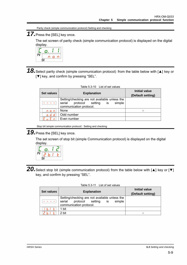
3.1 Precautions wiring communication .........................................................................3-1 3.2 Communication specification...................................................................................3-1 3.3 Connected explanation .............................................................................................3-2
Chapter 4 MODBUS communication function.................................. 4-1 4.1 Precautions for communication ...............................................................................4-1
4.1.1 Precautions after wiring and before communication .......................................................... 4-1 4.1.2 Precautions for communicating .......................................................................................... 4-2
4.2 Communication specification...................................................................................4-2 4.3 Setting and checking.................................................................................................4-3
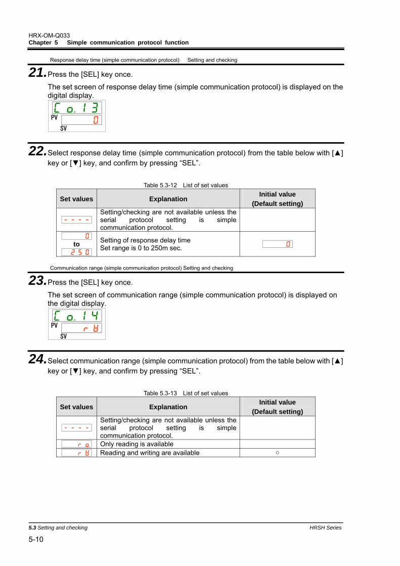
4.3.1 Setting and checking items................................................................................................. 4-3 4.3.2 Setting and checking .......................................................................................................... 4-4
4.4 Communication sequence ........................................................................................4-7 4.5 Message configuration..............................................................................................4-8
4.5.1 Message format.................................................................................................................. 4-8 4.5.2 Message example .............................................................................................................. 4-9
4.6 Function codes ........................................................................................................4-10 4.7 LRC............................................................................................................................4-10 4.8 Explanation of function codes................................................................................4-11
4.8.1 Function code:03 Reading multiple registers..................................................................4-11 4.8.2 Function code:06 Writing registers ................................................................................ 4-12
HRX-OM-Q033 Contents
HRSH Series
4.8.3 Function code:16 Writing multiple registers ...................................................................4-13 4.8.4 Function code:23 Reading/writing multiple registers .....................................................4-14
4.10.1 Circulating fluid discharge temperature ............................................................................4-17 4.10.2 Circulating fluid discharge pressure..................................................................................4-17 4.10.3 Circulating fluid discharge pressure..................................................................................4-17 4.10.4 Circulating fluid electric conductivity .................................................................................4-17 4.10.5 Status flag .........................................................................................................................4-18 4.10.6 Alarm flag ..........................................................................................................................4-19 4.10.7 Circulating fluid set temperature .......................................................................................4-21 4.10.8 Operation Start Command ................................................................................................4-21
Chapter 5 Simple communication protocol function ...................... 5-1 5.1 Precautions for communication ...............................................................................5-1
5.1.1 Precautions after wiring and before communication...........................................................5-1 5.1.2 Precautions for communicating...........................................................................................5-2 5.1.3 Precautions after the completion of the communication.....................................................5-2
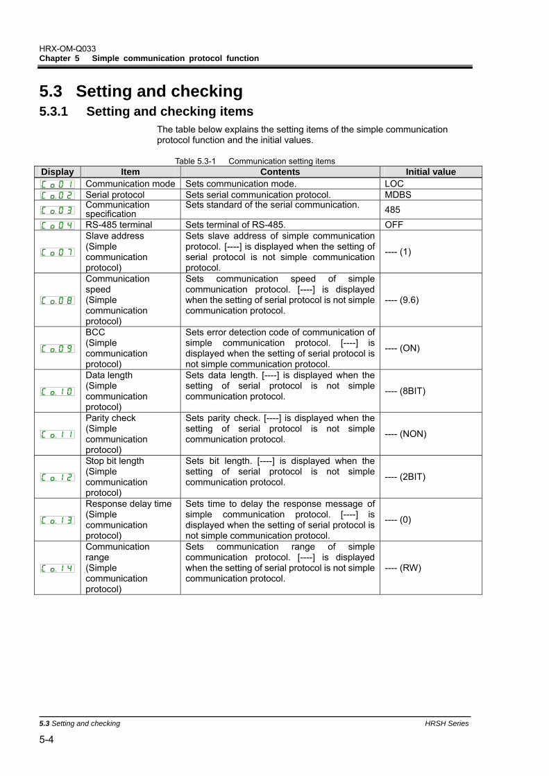
5.2 Communication specification...................................................................................5-3 5.3 Setting and checking.................................................................................................5-4
5.3.1 Setting and checking items.................................................................................................5-4 5.3.2 Setting and checking...........................................................................................................5-5
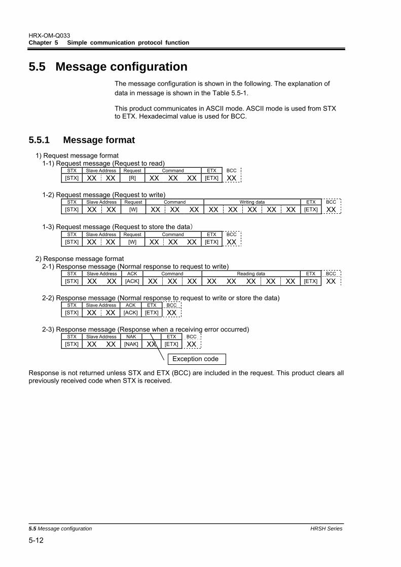
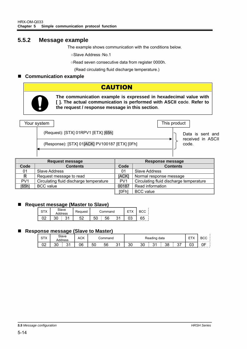
5.4 Communication sequence ...................................................................................... 5-11 5.5 Message configuration............................................................................................5-12
5.5.1 Message format ................................................................................................................5-12 5.5.2 Message example.............................................................................................................5-14
5.8.1 Command:PV1 Circulating fluid discharge temperature...................................................5-16 5.8.2 Command:SV1 Circulating fluid set temperature (R)........................................................5-17 5.8.3 Command:SV1 Circulating fluid set temperature (W).......................................................5-18 5.8.4 Command:LOC Key-lock setting (R) ................................................................................5-19 5.8.5 Command:LOC Key-lock setting (W)................................................................................5-20 5.8.6 Command:STR Saves data (W) .......................................................................................5-21
5.9 Negative response...................................................................................................5-22 Chapter 6 Communication alarm function ....................................... 6-1
6.1 Communication alarm occurs ..................................................................................6-1 6.2 Communication alarm reset......................................................................................6-2 6.3 Setting and checking.................................................................................................6-2
6.3.1 Setting and checking items.................................................................................................6-2
HRX-OM-Q033 Contents
HRSH Series
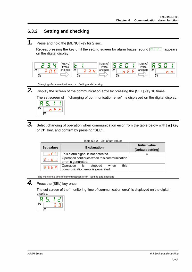
6.3.2 Setting and checking .......................................................................................................... 6-3
HRX-OM-Q033 Chapter 1 Read before using
HRSH Series 1.1 Communication mode and operation method 1-1
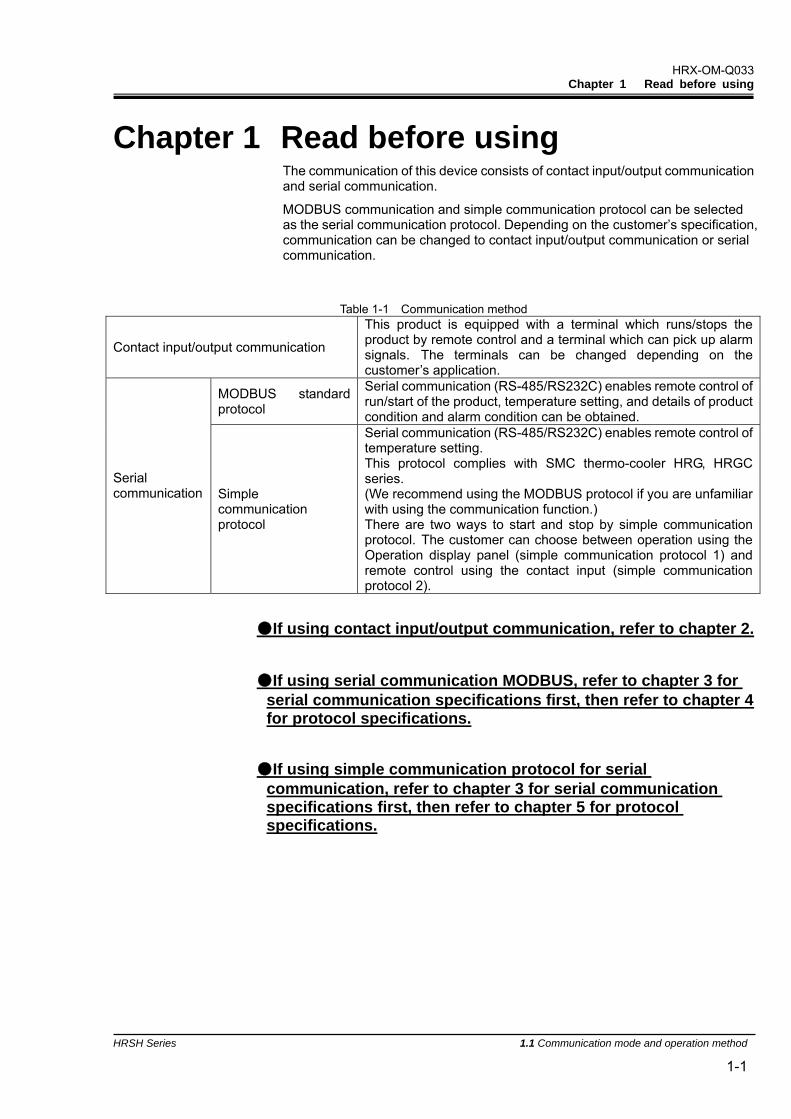
Chapter 1 Read before using The communication of this device consists of contact input/output communication and serial communication.
MODBUS communication and simple communication protocol can be selected as the serial communication protocol. Depending on the customer’s specification, communication can be changed to contact input/output communication or serial communication.
Table 1-1 Communication method
Contact input/output communication
This product is equipped with a terminal which runs/stops the product by remote control and a terminal which can pick up alarm signals. The terminals can be changed depending on the customer’s application.
MODBUS standard protocol
Serial communication (RS-485/RS232C) enables remote control of run/start of the product, temperature setting, and details of product condition and alarm condition can be obtained.
Serial communication Simple
communication protocol
Serial communication (RS-485/RS232C) enables remote control of temperature setting. This protocol complies with SMC thermo-cooler HRG, HRGC series. (We recommend using the MODBUS protocol if you are unfamiliar with using the communication function.) There are two ways to start and stop by simple communication protocol. The customer can choose between operation using the Operation display panel (simple communication protocol 1) and remote control using the contact input (simple communication protocol 2).
If using contact input/output communication, refer to chapter 2.
If using serial communication MODBUS, refer to chapter 3 for serial communication specifications first, then refer to chapter 4 for protocol specifications.
If using simple communication protocol for serial communication, refer to chapter 3 for serial communication specifications first, then refer to chapter 5 for protocol specifications.
HRX-OM-Q033 Chapter 1 Read before using
1.1 Communication mode and operation method HRSH Series
1-2
1.1 Communication mode and operation method LOCAL, DIO and SERIAL are available as the communication modes. Table 1.1-1 explains the communication modes. The default setting is LOCAL.
The operation method depends on the communication mode. Table 1.1-2 shows how the communication mode and method of operation are related.
The operation of the product functions depends on the communication mode. Table 1.1-3 shows how the communication mode and functions of this product are related.
Table 1.1-1 Communication modes
Communication mode Explanation LOCAL Mode allowing the product to be operated by the operation panel.
Mode allowing the product to be operated by the contact input/output communication. When the communication mode is “DIO”, operation mode automatically becomes “DIO REMOTE”. "DIO REMOTE” and “DIO LOCAL” can be selected by DIO communication signal.
DIO REMOTE: Contact input/output communication takes control of the operation of the product. The [REMOTE] lamp on the operation panel turns on.
DIO
DIO LOCAL: Operation control of the product is the same as that of LOCAL. The [REMOTE] lamp on the operation panel turns off.
SERIAL Mode allowing the product to be operated by serial communication. MODBUS/ simple communication protocol can be selected.
Table 1.1-2 Communication mode and operation
DIO SERIAL Simple
communication protocol pattern
LOCAL DIO LOCAL
DIO REMOTE MODBUS
1 2 Run/Stop control with operation display panel x x x Circulating fluid discharge temperature setting control with operation display panel x x Except above with operation display panel Condition reading with operation display panel Run/Stop operation by contact input/output communication x x x x Condition reading by contact input/output communication Reading of the external switch *1 *1 *1 Run/Stop operation by serial communication. x x x x Circulating fluid discharge temperature setting control by serial communication. x x x Condition reading by serial communication. ∗1: Only one external switch can be installed.
Table 1.1-3 Communication mode and product functions DIO SERIAL
Simple communication protocol pattern
LOCAL DIO LOCAL
DIO REMOTE MODBUS
1 2
Run timer x x x Stop timer x x x Recovery from power cut x x x Anti-freezing Pump accumulated operating time reset x x x Warming up function
Snow coverage protect function*2
∗2: This function cannot be set on the products of the cooling method ‘-W’.
HRX-OM-Q033 Chapter 1 Read before using
HRSH Series 1.2 Communication port 1-3
1.2 Communication port The communication port at the back of the product is used for communication. Fig 1.2-1 Communication port shows the location of the communication port.
Fig 1.2-1 Communication port
Contact input/output(DIO) Connector for communication Used for DIO communication.
Serial communication Connector Used for RS-485/RS-232C.
Connector for option Not used for communication.
HRX-OM-Q033 Chapter 1 Read before using
1.3 Key operations HRSH Series
1-4
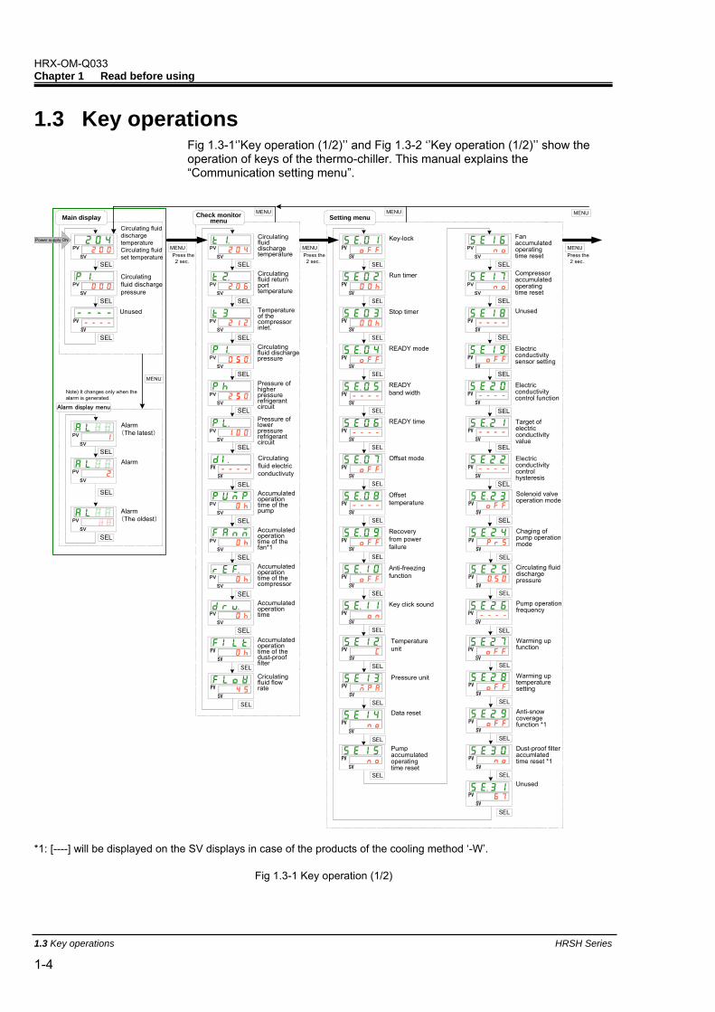
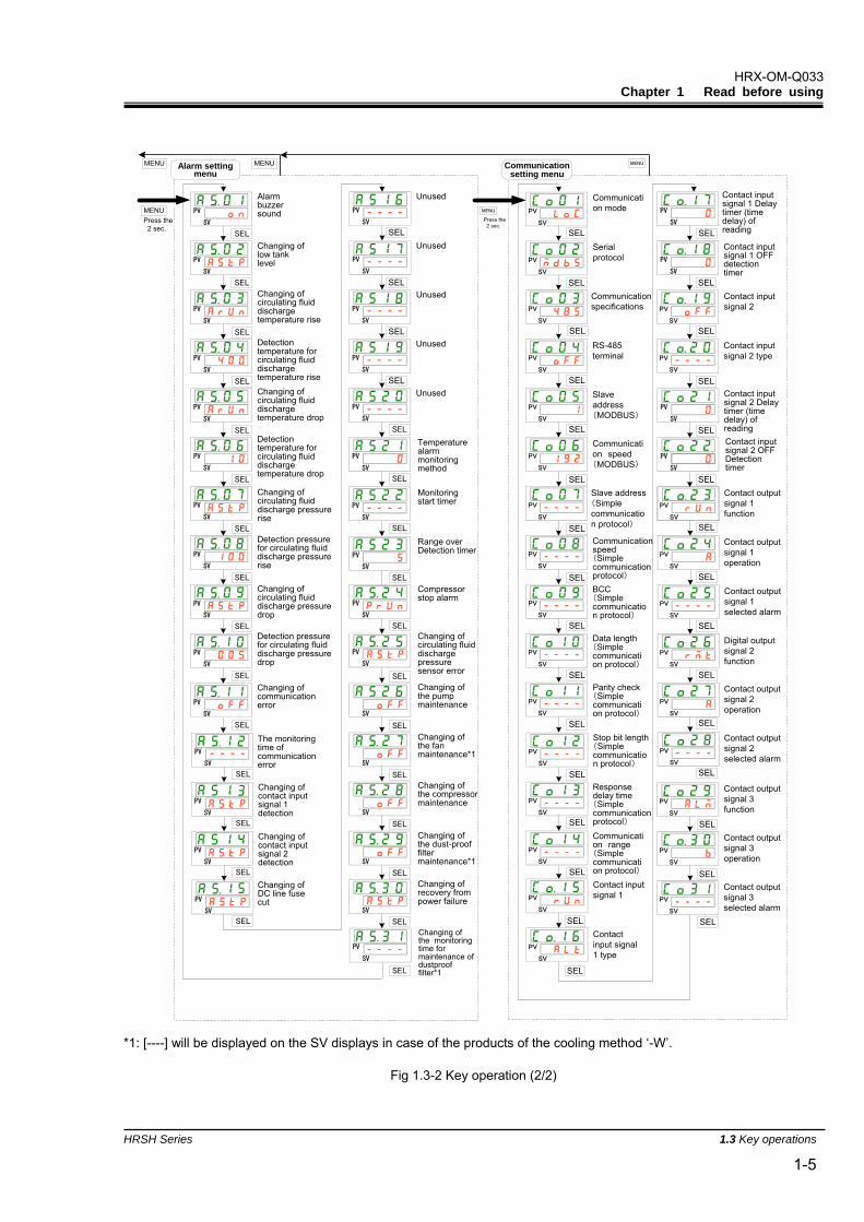
1.3 Key operations Fig 1.3-1‘’Key operation (1/2)’’ and Fig 1.3-2 ‘’Key operation (1/2)’’ show the operation of keys of the thermo-chiller. This manual explains the “Communication setting menu”.
PV
SV
Circulating fluiddischargetemperatureCirculating fluidset temperature
Circulatingfluid dischargepressure
Main display
Circulatingfluiddischargetemperature
Circulatingfluid returnporttemperature
Check monitormenu
Temperatureof thecompressorinlet.
PV
SV
PV
SV
PV
SV
PV
SV
Circulatingfluid dischargepressure
PV
SV
Pressure ofhigherpressurerefrigerantcircuit
PV
SV
Pressure oflowerpressurerefrigerantcircuit
Accumulatedoperationtime of thepump
Accumulatedoperationtime of thefan*1
Accumulatedoperationtime of thecompressor
Accumulatedoperationtime
PV
SV
PV
SV
PV
SV
PV
SV
Key-lock
Run timer
Setting menu
Stop timer
READY mode
READYband width
READY time
Offset mode
Offsettemperature
Recoveryfrom powerfailure
Anti-freezingfunction
Data reset
Pumpaccumulatedoperatingtime reset
Fanaccumulatedoperatingtime reset
Compressoraccumulatedoperatingtime reset
Key click sound
Temperatureunit
Pressure unit
Alarm(The latest)
Alarm
Alarm display menu
Alarm(The oldest)
PV
SV
PV
SV
PV
SV
Note) It changes only when thealarm is generated.
PV
SV
PV
SV
Power supply ON
PV
SV
Press the 2 sec.
PV
SV
Circulatingfluid electricconductivuty
PV
SV
SEL
UnusedPV
SV
PV
SV
Unused
Electricconductivitysensor setting
SEL
Electricconductivitycontrol function
PV
SV
Target ofelectricconductivityvalue
Electricconductivitycontrolhysteresis
PV
SV
PV
SV
SEL
SEL
SEL
SEL
SEL
SEL
SEL
SEL
SEL
SEL
SEL
SEL
SEL
SEL
SEL
SEL
SEL
SEL
SEL
SEL
SEL
SEL
SEL
MENU
MENUPress the 2 sec.
MENU
MENUMENU
Solenoid valveoperation mode
PV
SV
SEL
PV
SV
SEL
Accumulatedoperationtime of thedust-prooffilter
PV
SV
PV
SV
PV
SV
PV
SV
PV
SV
PV
SV
PV
SV
PV
SV
PV
SV
PV
SV
PV
SV
PV
SV
PV
SV
PV
SV
PV
SV
SEL
SEL
SEL
SEL
SEL
SEL
SEL
SEL
SEL
SEL
SEL
SEL
SEL
SEL
SEL
PV
SV
PV
SV
SEL
SEL
PV
SV
PV
SV
PV
SV
SEL
SEL
SEL
PV
SV
SEL
SEL
PV
SV
Chaging ofpump operationmode
Circulating fluiddischargepressure
Pump operationfrequency
Warming upfunction
Warming uptemperaturesetting
Anti-snowcoveragefunction *1
Dust-proof filteraccumlatedtime reset *1
MENUPress the 2 sec.
MENU
SEL
Criculatingfluid flowratePV
SV
SEL
PV
SV
Unused
*1: [----] will be displayed on the SV displays in case of the products of the cooling method ‘-W’.
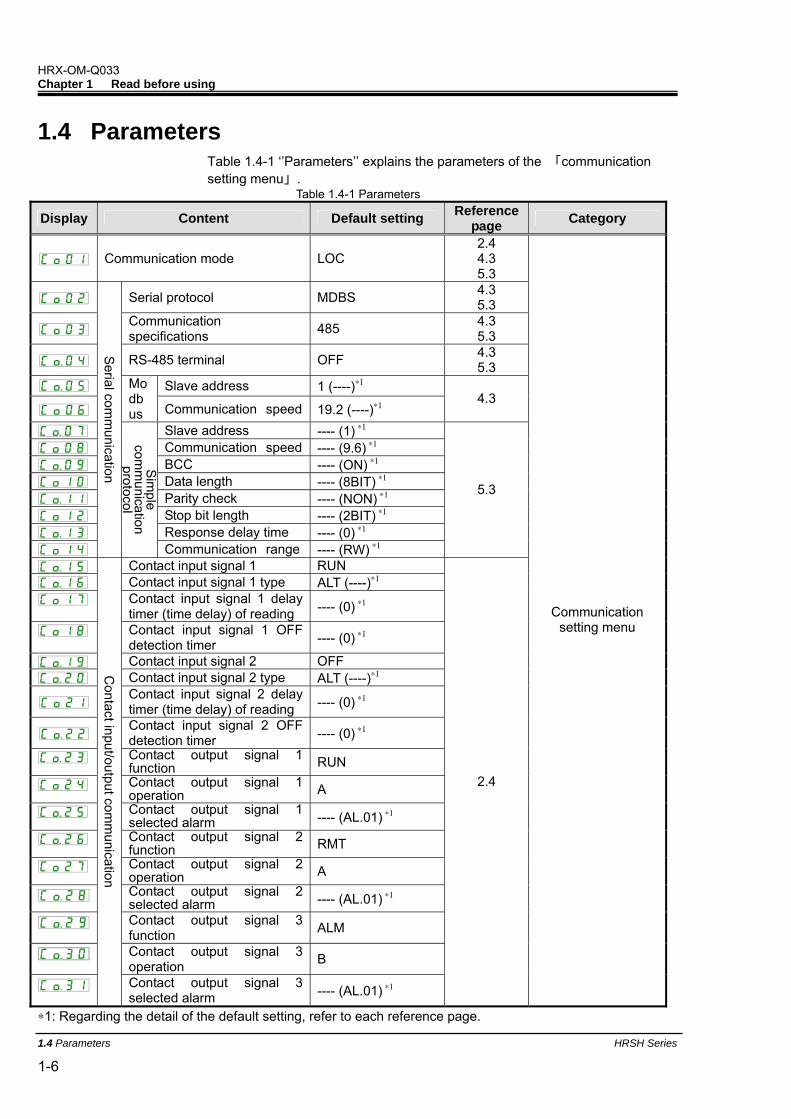
Slave address ---- (1) ∗1 Communication speed ---- (9.6) ∗1 BCC ---- (ON) ∗1 Data length ---- (8BIT) ∗1 Parity check ---- (NON) ∗1 Stop bit length ---- (2BIT) ∗1 Response delay time ---- (0) ∗1
Serial com
munication
Sim
ple com
munication
protocol
Communication range ---- (RW) ∗1
5.3
Contact input signal 1 RUN Contact input signal 1 type ALT (----)∗1 Contact input signal 1 delay
timer (time delay) of reading ---- (0) ∗1
Contact input signal 1 OFF detection timer ---- (0) ∗1
Contact input signal 2 OFF Contact input signal 2 type ALT (----)∗1
Contact input signal 2 delay timer (time delay) of reading ---- (0) ∗1
Contact input signal 2 OFF detection timer ---- (0) ∗1
Contact output signal 1 function RUN
Contact output signal 1 operation A
Contact output signal 1 selected alarm ---- (AL.01) ∗1
Contact output signal 2 function RMT
Contact output signal 2 operation A
Contact output signal 2 selected alarm ---- (AL.01) ∗1
Contact output signal 3 function ALM
Contact output signal 3 operation B
Contact input/output com
munication
Contact output signal 3 selected alarm ---- (AL.01) ∗1
2.4
Communication setting menu
∗1: Regarding the detail of the default setting, refer to each reference page.
HRX-OM-Q033 Chapter 2 Contact input/output communication
HRSH Series 2.1 Precautions for communication 2-1
Chapter 2 Contact input/output communication The device is equipped with a terminal which runs/stops the product. It is also equipped with a terminal which picks up operation signals, alarm signals and setting condition.
The device starts contact input/output communication according to the setting of the operation display panel. Contact input/output communication can be customized by changing the settings. Table 2-1 ‘’Customizable content’’ shows the contents which can be changed by the operation display panel.
Table 2-1 Customizable content
Signal Can be changed Contact input signal(2pcs.) Signal configuration(Alternate/Momentary)
Contact output signal(3pcs.) Type of signal, signal operation(N.O type / N.C type)
2.1 Precautions for communication 2.1.1 Precautions wiring communication
Communication wiring
A communication cable that connects the product and customer system is not included with the product. Please prepare a cable, referring to 2.3 ‘’Terminal block explanation. In order to avoid malfunction, do not connect to any place other than those shown in 2.3 ‘’Terminal block explanation.
Power supply
To use the power of the product, the total load current must be 500mA or less.
If the load is 500mA or more, the internal fuse is cut to protect the product and the alarm [AL21 DC line fuse cut] is generated. Refer to the “Installation / Operation” of the operation manual for alarms.
2.1.2 Precautions after wiring and before communication Check or set the communication mode by the operation display panel.
・ Communication mode shall be DIO.
Other modes can perform reading, but only DIO mode can perform writing.
HRX-OM-Q033 Chapter 2 Contact input/output communication
2.2 Communication specification HRSH Series
2-2
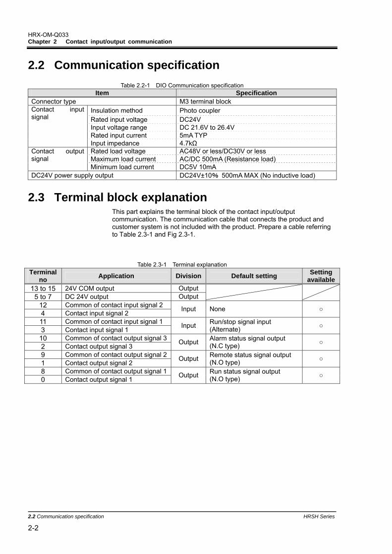
2.2 Communication specification
Table 2.2-1 DIO Communication specification Item Specification
Connector type M3 terminal block Insulation method Photo coupler Rated input voltage DC24V Input voltage range DC 21.6V to 26.4V Rated input current 5mA TYP
Contact input signal
Input impedance 4.7kΩ Rated load voltage AC48V or less/DC30V or less Maximum load current AC/DC 500mA (Resistance load)
Contact output signal
Minimum load current DC5V 10mA DC24V power supply output DC24V±10% 500mA MAX (No inductive load)
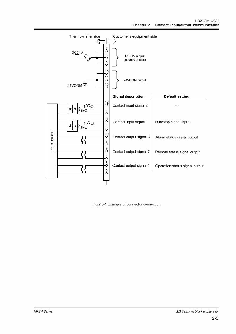
2.3 Terminal block explanation This part explains the terminal block of the contact input/output communication. The communication cable that connects the product and customer system is not included with the product. Prepare a cable referring to Table 2.3-1 and Fig 2.3-1.
Table 2.3-1 Terminal explanation
Terminal no Application Division Default setting Setting
available13 to 15 24V COM output Output 5 to 7 DC 24V output Output
12 Common of contact input signal 2 4 Contact input signal 2 Input None
11 Common of contact input signal 1 3 Contact input signal 1 Input Run/stop signal input
(Alternate)
10 Common of contact output signal 32 Contact output signal 3 Output Alarm status signal output
(N.C type)
9 Common of contact output signal 21 Contact output signal 2 Output Remote status signal output
(N.O type)
8 Common of contact output signal 10 Contact output signal 1 Output Run status signal output
(N.O type)
HRX-OM-Q033 Chapter 2 Contact input/output communication
HRSH Series 2.3 Terminal block explanation 2-3
4.7kΩ
Internal circuit
DC24V
24VCOM
1kΩ
4.7kΩ1kΩ
---
0
8
1
9
2
10
3
11
4
12
13
14
15
7
5
6 DC24V output(500mA or less)
24VCOM output
Contact output signal 3
Contact input signal 1
Contact output signal 1
Contact output signal 2
Contact input signal 2
Alarm status signal output
Run/stop signal input
Operation status signal output
Remote status signal output
Thermo-chiller side Cuctomer's equipment side
Signal description Default setting
Fig 2.3-1 Example of connector connection
HRX-OM-Q033 Chapter 2 Contact input/output communication
2.4 Setting and checking HRSH Series
2-4
2.4 Setting and checking 2.4.1 Setting and checking
The table below explains the setting items of the contact input/output signal and the initial values.
Table 2.4-1 List of set communication items Display Item Contents Default setting
Communication mode Sets communication mode of this product. LOC Contact input signal 1 Sets the function of contact input signal 1. RUN
Contact input signal 1 type Sets input type of contact input signal 1. [----] is displayed when the setting of contact input signal 1 is OFF.
ALT (----)
Contact input signal 1 delay timer of reading
Sets the delay timer of reading of contact input signal 1. Used when the setting of the contact input signal 1 is SW_A or SW_B. [----] is displayed when the setting of the contact input signal 1 is not SW_A or SW_B.
---- (0)
Contact input signal 1 OFF Detection timer
Sets the OFF detection timer of contact input signal 1. Used when the setting of the contact input signal 1 is SW_A or SW_B. [----] is displayed when the setting of the contact input signal 1 is not SW_A or SW_B.
---- (0)
Contact input signal 2 Sets the function of contact input signal 2. OFF
Contact input signal 2 type Sets input type of contact input signal 2. [----] is displayed when the setting of contact input signal 2 is OFF.
ALT (----)
Contact input signal 2 delay timer of reading
Sets the delay timer of reading of contact input signal 2. Used when the setting of the contact input signal 2 is SW_A or SW_B [----] is displayed when the setting of the contact input signal 2 is not SW_A or SW_B.
---- (0)
Contact input signal 2 OFF Detection timer
Sets the OFF detection timer of contact input signal 2. Used when the setting of the contact input signal 2 is SW_A or SW_B. [----] is displayed when the setting of the contact input signal 2 is not SW_A or SW_B.
---- (0)
Contact output signal 1 function Sets output signal function of contact output 1. RUN
Contact output signal 1 operation Sets output signal operation of contact output 1. A
Contact output signal 1 selected alarm
Sets alarm which is selected for contact output 1. [----] is displayed when the setting of the output signal of contact output1 is not selected alarm signal.
---- (AL.01)
Contact output signal 2 function Sets output signal function of contact output 2. RMT
Contact output signal 2 operation Sets output signal operation of contact output 2. A
Contact output signal 2 selected alarm
Sets alarm which is selected for contact output 2. [----] is displayed when the setting of the output signal of contact output2 is not selected alarm signal.
---- (AL.01)
Contact output signal 3 function Sets output signal function of contact output 3. ALM
Contact output signal 3 operation Sets output signal operation of contact output 3. B
Contact output signal 3 selected alarm
Sets alarm which is selected for contact output 3. [----] is displayed when the setting of the output signal of contact output3 is not selected alarm signal.
---- (AL.01)
HRX-OM-Q033 Chapter 2 Contact input/output communication
HRSH Series 2.4 Setting and checking 2-5
If the communication mode is set to [DIO] first while the operating signal is input, the product will start and feed the circulating fluid before the details are set. For safety, set the communication mode to [DIO] after carrying out the setting below.
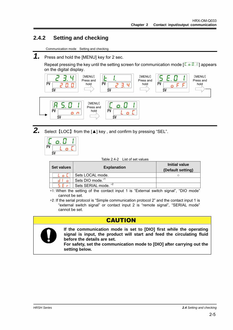
2.4.2 Setting and checking
Communication mode Setting and checking
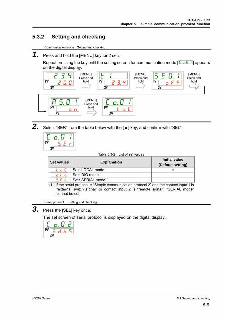
1. Press and hold the [MENU] key for 2 sec.
Repeat pressing the key until the setting screen for communication mode [ ] appears on the digital display.
PV
SV
PV
SV
PV
SV
PV
SV
PV
SV
2. Select【LOC】from the [] key , and confirm by pressing “SEL”.
PV
SV Table 2.4-2 List of set values
Set values Explanation Initial value
(Default setting) Sets LOCAL mode. Sets DIO mode.∗1 Sets SERIAL mode. ∗2
∗1:When the setting of the contact input 1 is “External switch signal”, “DIO mode” cannot be set.
∗2:If the serial protocol is “Simple communication protocol 2” and the contact input 1 is “external switch signal” or contact input 2 is “remote signal”, “SERIAL mode” cannot be set.
[MENU] Press and
hold
[MENU] Press and
hold
[MENU] Press and
hold
[MENU] Press and
hold
HRX-OM-Q033 Chapter 2 Contact input/output communication
2.4 Setting and checking HRSH Series
2-6
Contact input signal1 Setting and checking
3. Display the screen of contact input signal 1 by pressing the [SEL] key several times.
The set screen of contact input signal 1 is displayed on the digital display.
PV
SV
4. Select contact input signal 1 from the table below with [] key or [] key, and confirm by pressing “SEL”.
Table 2.4-3 List of set values
Set values Explanation Initial value
(Default setting) Without signal input Run/stop signal input
External switch signal input (N.O. type)∗1,∗2
External switch signal input (N.C. type) ∗1,∗2
∗1:When the setting of the communication mode is “DIO mode”, “External switch signal input” cannot be set.
∗2:When the setting of the communication mode is “SEIRAL mode” and the protocol setting is “Simplified communication protocol 2”, “External switch signal input” cannot be set.
Contact input signal 1 type Setting and checking
5. Press the [SEL] key once.
The set screen of contact input signal 1 type is displayed on the digital display.
PV
SV
6. Select contact input signal 1 type from the table below with [] key or [] key, and confirm by pressing “SEL”.
Table 2.4-4 List of set values
Set values Explanation Initial value
(Default setting)
Setting/checking are not available if the setting of contact input signal 1 is OFF.
Alternate signal Momentary signal∗1
∗1:Used when the setting of the contact input 1 is “Operation stop signal input”.
HRX-OM-Q033 Chapter 2 Contact input/output communication
HRSH Series 2.4 Setting and checking 2-7
Contact input signal 1 delay timer of reading Setting and checking
7. Press the [SEL] key once.
The set screen of the contact input signal 1 delay timer of reading is displayed on the digital display.
PV
SV
8. Select contact input signal 1 delay timer of reading from the table below with [] key or [] key, and confirm by pressing “SEL”.
Table 2.4-5 List of set value
Set value Explanation Initial value (Default setting)
Setting and checking are not available unless contact input signal 1 is external switch signal input (N.O. type or N.C. type).
to Setting of contact input signal 1 delay timer of reading. Set range is 0 to 300 sec.
Contact input signal 1 OFF detection timer Setting and checking
9. Press the [SEL] key once.
The set screen of the contact input signal 1 OFF detection timer is displayed on the digital display.
PV
SV
10. Select contact input signal 1 OFF detection timer from the table below with [] key or [] key, and confirm by pressing “SEL”.
Table 2.4-6 List of set value
Set value Explanation Initial value (Default setting)
Setting and checking are not available unless contact input signal 1 is external switch signal input (N.O. type or N.C. type).
to Setting of contact input signal 1 OFF detection timer Set range is 0 to 10sec.
HRX-OM-Q033 Chapter 2 Contact input/output communication
2.4 Setting and checking HRSH Series
2-8
Contact input signal 1 Setting and checking
11. Press the [SEL] key once.
The set screen of contact input signal 2 is displayed on the digital display.
PV
SV
12. Select contact input signal 2 from the table below with [] key or [] key, and confirm by pressing “SEL”.
Table 2.4-7 List of set values
Set values Explanation Initial value
(Default setting) Without signal input Run/stop signal input
External switch signal input (N.O. type)
External switch signal input (N.C. type)
Remote signal input∗1 ∗1:When the setting of the serial protocol is “Simplified communication protocol 2”,
“Remote signal input” cannot be set.
Contact input signal 2 type Setting and checking
13. Press the [SEL] key once.
The set screen of contact input signal 2 type is displayed on the digital display.
PV
SV
14. Select contact input signal 2 type from the table below with [] key or [] key, and confirm by pressing “SEL”.
Table 2.4-8 List of set values
Set values Explanation Initial value
(Default setting)
Setting/checking are not available if the setting of contact input signal 2 is OFF.
Alternate signal Momentary signal∗1
∗1:Can be set when the setting of contact input signal 2 is "Run/Stop signal input" or "Remote signal"
HRX-OM-Q033 Chapter 2 Contact input/output communication
HRSH Series 2.4 Setting and checking 2-9
Contact input signal 2 delay timer of reading Setting and checking
15. Press the [SEL] key once.
The set screen of contact input signal 2 delay timer of reading is displayed on the digital display.
PV
SV
16. Select contact input signal 2 delay timer of reading from the table below with [] key or [] key, and confirm by pressing “SEL”.
Table 2.4-9 List of set values
Set values Explanation Initial value
(Default setting) Setting and checking are not available unless contact input signal 2 is external switch signal input (N.O. type or N.C. type).
to Setting of contact input signal 2 delay timer of reading. Set range is 0 to 300 sec.
Contact input signal 2 OFF detection timer Setting and checking
17. Press the [SEL] key once.
The set screen of contact input signal 2 OFF detection timer is displayed on the digital display.
PV
SV
18. Select contact input signal 2 OFF detection timer from the table below with [] key or [] key, and confirm by pressing “SEL”.
Table 2.4-10 List of set values
Set values Explanation Initial value
(Default setting) Setting and checking are not available unless contact input singal 2 is external switch signal input(N.O. type or N.C. type).
to Setting of contact input signal 2 OFF detection timer. Set range is 0 to 10 sec.
HRX-OM-Q033 Chapter 2 Contact input/output communication
2.4 Setting and checking HRSH Series
2-10
Contact output signal 1 function Setting and checking
19. Press the [SEL] key once.
The set screen of contact output signal 1 function is displayed on the digital display.
PV
SV
20. Select contact output signal 1 function from the table below with [] key or [] key, and confirm by pressing “SEL”.
Table 2.4-11 List of set values
Set values Explanation Initial value
(Default setting) Without signal output Operation status signal output Remote status signal output Ready completion (TEMP READY) signal output Operation stop alarm signal output Operation continuation alarm signal output Alarm status signal output Selected alarm status signal output Operation start timer setting status signal output Operation stop timer setting status signal output Recovery from power failure setting status signal output Anti-freezing setting status signal output Contact input signal 1 pass through signal output Contact input signal 2 pass through signal output
Warming up function setting status output
Anti-snow coverage function setting status output∗1 ∗1: Anti-snow coverage function cannot be set on the products of the cooling method ‘-W’.
Contact output signal 1 operation Setting and checking
21. Press the [SEL] key once.
The set screen of contact output signal 1 operation is displayed on the digital display.
PV
SV
HRX-OM-Q033 Chapter 2 Contact input/output communication
HRSH Series 2.4 Setting and checking 2-11
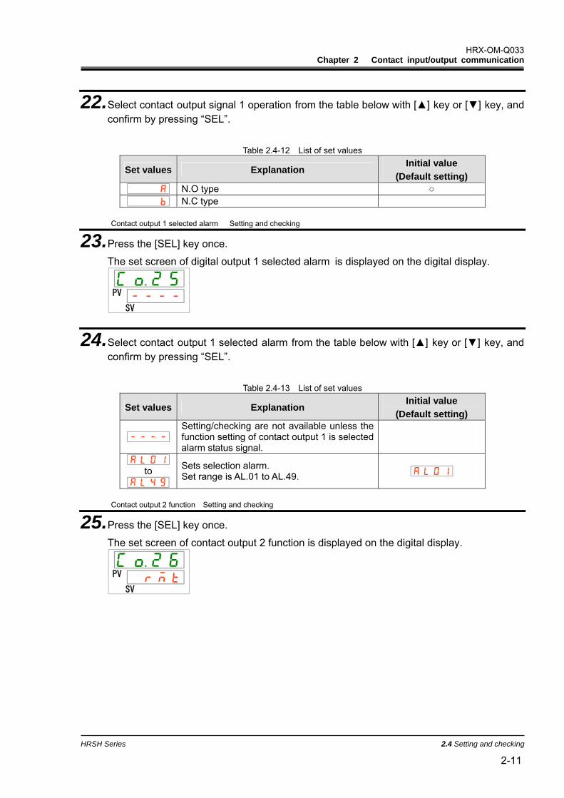
22. Select contact output signal 1 operation from the table below with [] key or [] key, and confirm by pressing “SEL”.
Table 2.4-12 List of set values
Set values Explanation Initial value
(Default setting) N.O type N.C type
Contact output 1 selected alarm Setting and checking
23. Press the [SEL] key once.
The set screen of digital output 1 selected alarm is displayed on the digital display.
PV
SV
24. Select contact output 1 selected alarm from the table below with [] key or [] key, and confirm by pressing “SEL”.
Table 2.4-13 List of set values
Set values Explanation Initial value
(Default setting) Setting/checking are not available unless the function setting of contact output 1 is selected alarm status signal.
to Sets selection alarm. Set range is AL.01 to AL.49.
Contact output 2 function Setting and checking
25. Press the [SEL] key once.
The set screen of contact output 2 function is displayed on the digital display.
PV
SV
HRX-OM-Q033 Chapter 2 Contact input/output communication
2.4 Setting and checking HRSH Series
2-12
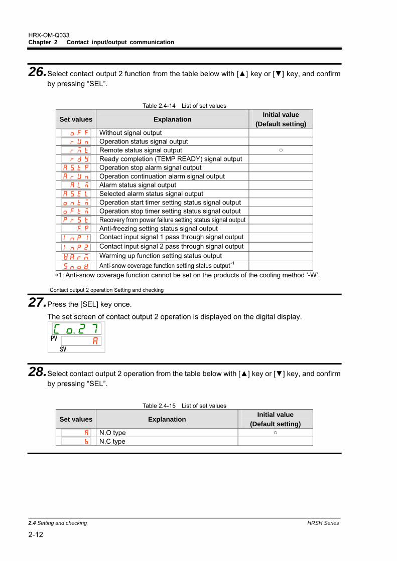
26. Select contact output 2 function from the table below with [] key or [] key, and confirm by pressing “SEL”.
Table 2.4-14 List of set values
Set values Explanation Initial value
(Default setting) Without signal output Operation status signal output Remote status signal output Ready completion (TEMP READY) signal output Operation stop alarm signal output Operation continuation alarm signal output Alarm status signal output Selected alarm status signal output Operation start timer setting status signal output Operation stop timer setting status signal output Recovery from power failure setting status signal output Anti-freezing setting status signal output
Contact input signal 1 pass through signal output
Contact input signal 2 pass through signal output
Warming up function setting status output
Anti-snow coverage function setting status output∗1 ∗1: Anti-snow coverage function cannot be set on the products of the cooling method ‘-W’.
Contact output 2 operation Setting and checking
27. Press the [SEL] key once.
The set screen of contact output 2 operation is displayed on the digital display.
PV
SV
28. Select contact output 2 operation from the table below with [] key or [] key, and confirm by pressing “SEL”.
Table 2.4-15 List of set values
Set values Explanation Initial value
(Default setting) N.O type N.C type
HRX-OM-Q033 Chapter 2 Contact input/output communication
HRSH Series 2.4 Setting and checking 2-13
Contact output 2 selected alarm Setting and checking
29. Press the [SEL] key once.
The set screen of contact output 2 selected alarm is displayed on the digital display.
PV
SV
30. Select contact output 2 selected alarm from the table below with [] key or [] key, and confirm by pressing “SEL”.
Table 2.4-16 List of set values
Set values Explanation Initial value
(Default setting) Setting/checking are not available unless the function setting of contact output 2 is selected alarm status signal.
to Sets selection alarm. Set range is AL.01 to AL.49.
Contact output 3 function Setting and checking
31. Press the [SEL] key once.
The set screen of contact output 3 function is displayed on the digital display.
PV
SV
HRX-OM-Q033 Chapter 2 Contact input/output communication
2.4 Setting and checking HRSH Series
2-14
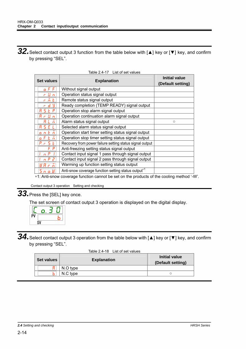
32. Select contact output 3 function from the table below with [] key or [] key, and confirm by pressing “SEL”.
Table 2.4-17 List of set values
Set values Explanation Initial value
(Default setting) Without signal output Operation status signal output Remote status signal output Ready completion (TEMP READY) signal output Operation stop alarm signal output Operation continuation alarm signal output Alarm status signal output Selected alarm status signal output Operation start timer setting status signal output Operation stop timer setting status signal output Recovery from power failure setting status signal output Anti-freezing setting status signal output Contact input signal 1 pass through signal output Contact input signal 2 pass through signal output
Warming up function setting status output
Anti-snow coverage function setting status output∗1 ∗1: Anti-snow coverage function cannot be set on the products of the cooling method ‘-W’.
Contact output 3 operation Setting and checking
33. Press the [SEL] key once.
The set screen of contact output 3 operation is displayed on the digital display.
PV
SV
34. Select contact output 3 operation from the table below with [] key or [] key, and confirm by pressing “SEL”.
Table 2.4-18 List of set values
Set values Explanation Initial value
(Default setting) N.O type N.C type
HRX-OM-Q033 Chapter 2 Contact input/output communication
HRSH Series 2.4 Setting and checking 2-15
Contact output 3 selected alarm Setting and checking
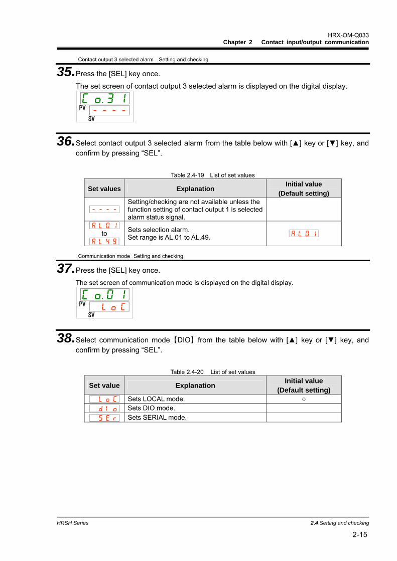
35. Press the [SEL] key once.
The set screen of contact output 3 selected alarm is displayed on the digital display.
PV
SV
36. Select contact output 3 selected alarm from the table below with [] key or [] key, and confirm by pressing “SEL”.
Table 2.4-19 List of set values
Set values Explanation Initial value
(Default setting) Setting/checking are not available unless the function setting of contact output 1 is selected alarm status signal.
to Sets selection alarm. Set range is AL.01 to AL.49.
Communication mode Setting and checking
37. Press the [SEL] key once. The set screen of communication mode is displayed on the digital display.
PV
SV
38. Select communication mode【DIO】from the table below with [] key or [] key, and confirm by pressing “SEL”.
Table 2.4-20 List of set values
Set value Explanation Initial value (Default setting)
Sets LOCAL mode. Sets DIO mode.
Sets SERIAL mode.
HRX-OM-Q033 Chapter 2 Contact input/output communication
2.5 Contact input signal HRSH Series
2-16
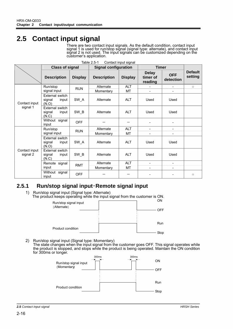
2.5 Contact input signal There are two contact input signals. As the default condition, contact input signal 1 is used for run/stop signal (signal type: alternate), and contact input signal 2 is not used. The input signals can be customized depending on the customer’s application.
Table 2.5-1 Contact input signal Class of signal Signal configuration Timer
Description Display Description DisplayDelay
timer of reading
OFF detection
Default setting
Alternate ALT - - Run/stop signal input RUN
Momentary MT - -
External switch signal input (N.O)
SW_A Alternate ALT Used Used
External switch signal input (N.C)
SW_B Alternate ALT Used Used
Contact input signal 1
Without signal input OFF - - - -
Alternate ALT - - Run/stop signal input RUN
Momentary MT - -
External switch signal input (N.O)
SW_A Alternate ALT Used Used
External switch signal input (N.C)
SW_B Alternate ALT Used Used
Alternate ALT - - Remote signal input RMT
Momentary MT - -
Contact input signal 2
Without signal input OFF - - - -
2.5.1 Run/stop signal input・Remote signal input 1) Run/stop signal input (Signal type: Alternate)
The product keeps operating while the input signal from the customer is ON.
2) Run/stop signal input (Signal type: Momentary)
The state changes when the input signal from the customer goes OFF. This signal operates while the product is stopped, and stops while the product is being operated. Maintain the ON condition for 300ms or longer.
OFF
ON
Run
StopProduct condition
Run/stop signal input ( Momentary )
300ms 300ms
OFF
ON
Run
StopProduct condition
Run/stop signal input ( Alternate )
HRX-OM-Q033 Chapter 2 Contact input/output communication
HRSH Series 2.5 Contact input signal 2-17
3) Remote signal input (Signal type: Alternate) The product becomes DIO REMOTE while the input signal from the customer is ON.
4) Remote signal input (Signal type: Momentary)
The state changes when the input signal from the customer goes OFF. If DIO LOCAL is set, it is switched to DIO REMOTE. If DIO REMOTE, it is switched to DIO LOCAL. Maintain the ON condition for 300ms or longer.
5) Contact input signal 1 is for Run/stop signal input (Signal type: Alternate), Contact input signal 2 is for external switch signal input (N.O. type) Refer to Chapter 2.5.2 for details of the external switch signal input.
① The product starts operation when the Run/stop signal from the user is turned on. ② It reads the signal of the external switch signal (N.O type) after the time which has been set for
the delay timer of reading. The factory default setting of the delay timer of reading is 0sec. Refer to 2.4.2 for setting. .
③ When the external switch signal (N.O. type) has been turned off for the time set for OFF detection timer, it is recognized as OFF. The factory default setting of the OFF detection timer is 0sec. Refer to 1.4.2 for setting.
④ AL32 contact input 2 signal detection alarm is generated. The operation of the product stops. "Operation stop" is the default setting for AL32. The product can be set to continue operation or not to detect the alarm. Refer to the “Installation / Operation” manual for details.
∗ The product stops operation when the Run/stop signal is turned off during operation. Afterwards, the alarm is not generated even if the external switch signal (N.O type) is turned off.
6) Input signal is not connected to either contact input signal 1 or contact input signal 2. This product cannot be controlled by the contact input.
7) Remote signal is connected to either contact input signal 1 or contact input signal 2. This product cannot be controlled by the contact input.
O FF
ON
Run
Stop Product condition
Run/Stop signal input
O FF
ON External switch signal input
Delay timer of reading
OFF Detection timer ③
④ ①
②
O FF
ON
DIO REMOTE
DIO LOCAL Product condition
Run/stop signal input ( Momentary )
300ms 300ms
O FF
ON
DIO REMOTE
DIO LOCAL Product condition
Remote signal input ( Alternate)
HRX-OM-Q033 Chapter 2 Contact input/output communication
2.5 Contact input signal HRSH Series
2-18
2.5.2 External switch signal input This product can be monitored during operation by reading the signal of the external switch prepared by the customer. The product stops monitoring when it stops operation. This product generates an alarm and stops operating when a problem is detected from the external switch. Select the external switch 1 or 2 or both depending on the customer’s system. Refer to 2.4.2 for setting. The number of monitored external switches depends on the communication mode. Refer to Table 2.5-2 In the communication mode in which the external switches 1 and 2 are available, two products can be monitored simultaneously. If a problem is detected by one or both external switches, an alarm is generated and the operation stops. You can set the product to continue operation or not to detect the alarm. Refer to the “Installation / Operation” manual for details
Table 2.5-2 Cross reference of communication modes and external switch monitoring
DIO SERIAL Simple
communication protocol pattern
LOCAL DIO LOCAL DIO REMOTE MODBUS1 2
External switch signal input 1 X X X External switch signal input 2
Run status of this product
Run
Stop
External switchsignal input
CLOSE
OPEN
Operation start
Signal readingstart
Delay timer of reading OFF detection timer
Alarmgeneration
Operationstops due tothe alarm.
Fig 2.5-1 Timing chart of external switch monitoring
Delay timer of reading If the signal of the external switch prepared by the customer is not closed instantly when the
product is operated, set the delay timer for reading. By setting this timer, the external switch monitoring starts after the time set by the delay time of reading since the operation start.
“0" is the default setting. Set a time which is suitable for your environment. Example When using a flow switch
When operation is started, it takes time for the fluid to reach the piping and the flow switch to detect the flow. Set the time for the flow switch to start.
OFF detection timer If you do not want the alarm to be generated instantly when the external switch prepared by the
customer is in open status, but instead want the alarm to be generated after the switch has been open for a specific time (continuous open status), set the OFF detection timer.
This timer enables the alarm to be generated when the time set for OFF detection time passes after the switch is in OPEN status.
The default setting is 0 sec. Set a time which is suitable for your application. Contact input
N.O type or N.C. type can be selected for the external switch. Set the signal which is suitable for the external switch prepared by the customer.
HRX-OM-Q033 Chapter 2 Contact input/output communication
HRSH Series 2.6 Contact output signal 2-19
2.6 Contact output signal There are three contact output signals. As the default setting, contact output signal 1 is for operating condition (N.O type), contact output signal 2 is for remote signal (N.O type), and contact output signal 3 is for alarm signal (N.C type). Refer to Table 2-6-1. .Depending on the product condition, contact output signal is turned on (closed) or turned off (open).
The signals can be customized depending on the customer’s application. The Table 2.6-2 shows operation of contact output signal.
【Tips】
All contact output signals are turned off (open) when the power is not supplied.
Table2.6-1 Contact output signal (Default setting) Class of signal Signal configuration Description Display Description Display Remarks
Contact output signal 1 Run status signal output RUN N.O type A
Contact output signal 2 Remote status signal output RMT N.O type A
Contact output signal 3 Alarm status signal output ALM N.C type B
Non generation (not set)
Generation set
ON
OFF
Contact output signal (N.O type)
Product condition(Set condition)
ON
OFF
Contact output signal (N.C type)
HRX-OM-Q033 Chapter 2 Contact input/output communication
2.6 Contact output signal HRSH Series
2-20
Table 2.6-2 Operation of contact output signal
Class of signal
Display Function Operation
Operation of contact output signal
N.O type Normally, output signal is OFF (open)
OFF Without signal output N.C
type Normally, output signal is ON (close) N.O type When the product operates, signal turns ON.
RUN Operation status signal output N.C
type When the product operates, signal turns OFF. N.O type When the product becomes DIO REMOTE, signal turns ON.
RMT Remote status signal output N.C
type When the product becomes DIO REMOTE, signal turns OFF.N.O type
When the product becomes the status of ready completion (TEMP READY), signal turns ON. RDY
Ready completion (TEMP READY) signal output
N.C type
When the product becomes the status of ready completion (TEMP READY), signal turns OFF.
N.O type When operation stop alarm occurs, signal turns ON.
A.STP Operation stop alarm signal output N.C
type When operation stop alarm occurs, signal turns OFF. N.O type When operation continuation alarm occurs, signal turns ON.
A.RUN Operation continuation alarm signal output
N.C type When operation continuation alarm occurs, signal turns OFF.N.O type When alarm occurs, signal turns ON.
ALM Alarm status signal output N.C
type When alarm occurs, signal turns OFF. N.O type When selected alarm occurs, signal turns ON.
A.SEL Selected alarm status signal output N.C
type When selected alarm occurs, signal urns ON. N.O type When run timer is set, signal turns ON.
ON.TM Operation start timer setting status signal output
N.C type When run timer is set, signal turns OFF. N.O type When stop timer is set, signal turns ON.
OF.TM Operation stop timer setting status signal output
N.C type When stop timer is set, signal turns OFF. N.O type When recovery from power failure is set, signal turns ON.
P.RST Recovery from power failure setting status signal output
N.C type When recovery from power failure is set, signal turns OFF.
N.O type When anti-freezing function is set, signal turns ON.
F.P. Anti-freezing setting status signal output N.C
type When anti-freezing function is set, signal turns OFF. N.O type
Outputs the same signal as input one to the contact input signal 1. Input signal is ON Output signal is ON INP1. ∗1
Contact input signal 1 pass through signal output N.C
type Outputs the opposite signal of input one to the contact input signal 1. Input signal is OFF Output signal is ON
N.O type
Outputs the same signal as input one to the contact input signal 2. Input signal is ON Output signal is ON INP2∗1
Contact input signal 2 pass through signal output N.C
type Outputs the opposite signal of input one to the contact input signal 2. Input signal is OFF Output signal is ON
N.O type When warming up function is set, signal turns ON.
WARM Warming up function setting status output
N.C type When warming up function is set, signal turns OFF. N.O type When anti-snow coverage function is set, signal turns ON.
SNOW∗2 Anti-snow coverage function setting status output
N.C type When anti-snow coverage function is set, signal turns OFF.
∗1: The signal can not output normally when selected momentary. ∗2: Anti-snow coverage function cannot be set on the products of the cooling method ‘-W’.
HRX-OM-Q033 Chapter 3 Serial communication
HRSH Series 3.1 Precautions wiring communication 3-1
Chapter 3 Serial communication Serial communication (RS-485/RS232C) enables the remote control of run/start of the product, temperature setting and details of product condition, and alarm condition can be obtained.
The operating state of the product (run/stop) and the temperature setting can be monitored by sending a request message made by the program of the host computer (e.g. PC).
MODBUS communication and simple communication protocol can be selected as the serial communication protocol. This chapter illustrates the common specifications of serial communication. Chapter 4 and 5 illustrate each protocol.
3.1 Precautions wiring communication Communication wiring A communication cable that connects the product and customer system is not included with the product. Please prepare a cable, referring to 3.3 ‘’Connected explanation’’ In order to avoid malfunction, do not connect to any place other than those shown in 3.3 ‘’Connected explanation’’.
3.2 Communication specification
Table 3.2-1 Serial communication specification Item Specification
Connector type (for the product) D-sub9P type Female connector Standard Select from EIA RS-485/RS-232C Circuit type Half duplex Half duplex Transmission type Start-stop Protocol MODBUS terminal∗1 /Simple communication protocol
Terminal resistance Select from with terminal resistance(120Ω)/Without terminal resistance
:Default setting ∗1:Refer to Modicon Co. protocol specifications "PI-MBUS-300 Rev.J".
HRX-OM-Q033 Chapter 3 Serial communication
3.3 Connected explanation HRSH Series
3-2
3.3 Connected explanation Fig 3.3-1 shows the wiring when RS-485 is selected as the communication standard. Fig shows the wiring when RS-232C is selected. A communication cable that connects the product and customer system is not included with the product. Prepare a cable, referring to Fig 3.3-1 or Fig.
1SD+
5SG
9SD-SD+ SD- SG
Terminalresistance
Master This product(first slave)
1SD+
5SG
9SD-
This product(second slave)
1SD+
5SG
9SD-
This product(31st slaves)
Terminalresistance120Ω
Fig 3.3-1 RS-485 connector connection
【Tips】
・1 master : 1 product, or 1 master: N products.
In the latter case, up to 31 products can be connected.
・Both ends of the communication connection (the end nodes) need to be connected to the higher level computer.
・The terminal resistance of this product can be set by the operation display panel. Refer to ‘’4.3.2 Setting and checking’’,’’5.3.2 Setting and checking’’.
2
3
5
R D
S D
S G
2
3
5
R D
S D
S G
Master This product Fig 3.3-2 RS-232C connector connection
HRX-OM-Q033 Chapter 4 MODBUS communication function
HRSH Series 4.1 Precautions for communication 4-1
Chapter 4 MODBUS communication function MODBUS protocol is a communication protocol developed by Modicon. It is used to communicate with a PC or PLC.
Register content is read and written by this communication protocol.
This communication has the following features.
・Controls run/stop.
・Sets and reads the circulating fluid set temperature.
・Reads the circulating fluid discharge temperature.
・Reads the condition of the product.
・Reads the alarm generating condition of the product.
Refer to “4.10 Register Map” for the register of the product.
4.1 Precautions for communication
4.1.1 Precautions after wiring and before communication Check or set the each communication setting by the operation display
panel.
・The communication specification shall be the customer’s communication standard.
・The serial protocol shall be the MODBUS.
・The communication mode shall be the SERIAL mode.
Other modes can perform reading, but only SERIAL mode can perform writing.
Check or set the communication parameters using the operation display panel.
Check or set the communication speed so that the product synchronizes with the host computer (master) prepared by the customer.
Check the slave address by the operation display panel.
No response is returned when a request message is sent from a slave address other than those set in the product.
HRX-OM-Q033 Chapter 4 MODBUS communication function
4.2 Communication specification HRSH Series
4-2
4.1.2 Precautions for communicating Allow a suitable interval between requests.
To send request messages in series, wait for 100 msec. or longer after receiving a response message from the product before sending the next message.
Retry (resend request message).
The response may not be returned due to noise. If no message is returned 1sec. after sending a request message, resend the request message.
If necessary send a read request message to check if it was written correctly.
Message to notify the completion of the process is returned when the action for the written request message is completed.
Send a read request message to confirm if the setting was written as requested.
Setting limit of circulating fluid temperature
When the circulating fluid set temperature is written by communication, the data is stored in FRAM. When the product restarts, it restarts with the value which was set before the restart. The number of times it is possible to overwrite FRAM is limited. Data is only stored in FRAM when it receives a circulating fluid set temperature which is different from the previous temperatures. Please check how many times it is possible to overwrite FRAM, and avoid unnecessary changes of the circulating fluid set temperature during communication
4.2 Communication specification
Table 4.2-1 Communication specification of MODBUS communication function Item Specification
Standard Select from EIA RS-485/RS-232C Communication speed Select from 9600bps/19200bps Data・bit length 7bit Stop・bit length 1bit Data transfer direction LSB Parity Even parity Letter code ASCII mode Slave address set range Select from 1 to 99 address Error check LRC method :Default setting
HRX-OM-Q033 Chapter 4 MODBUS communication function
HRSH Series 4.3 Setting and checking 4-3
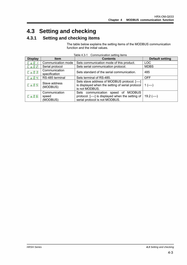
4.3 Setting and checking 4.3.1 Setting and checking items
The table below explains the setting items of the MODBUS communication function and the initial values.
Table 4.3-1 Communication setting items
Display Item Contents Default setting Communication mode Sets communication mode of this product. LOC Serial protocol Sets serial communication protocol. MDBS
Communication specification Sets standard of the serial communication. 485
RS-485 terminal Sets terminal of RS-485. OFF
Slave address (MODBUS)
Sets slave address of MODBUS protocol. [----] is displayed when the setting of serial protocol is not MODBUS.
1 (----)
Communication speed (MODBUS)
Sets communication speed of MODBUS protocol. [----] is displayed when the setting of serial protocol is not MODBUS.
19.2 (----)
HRX-OM-Q033 Chapter 4 MODBUS communication function
4.3 Setting and checking HRSH Series
4-4
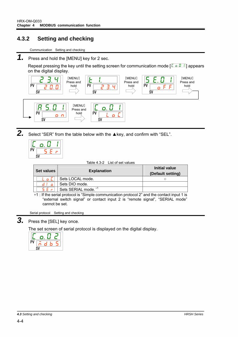
4.3.2 Setting and checking
Communication Setting and checking
1. Press and hold the [MENU] key for 2 sec.
Repeat pressing the key until the setting screen for communication mode [ ] appears on the digital display.
PV
SV
PV
SV
PV
SV
PV
SV
PV
SV
2. Select “SER” from the table below with the key, and confirm with “SEL”.
PV
SV Table 4.3-2 List of set values
Set values Explanation Initial value
(Default setting) Sets LOCAL mode. Sets DIO mode. Sets SERIAL mode. ∗1
∗1 : If the serial protocol is “Simple communication protocol 2” and the contact input 1 is “external switch signal” or contact input 2 is “remote signal”, “SERIAL mode” cannot be set.
Serial protocol Setting and checking
3. Press the [SEL] key once.
The set screen of serial protocol is displayed on the digital display.
PV
SV
[MENU] Press and
hold
[MENU] Press and
hold
[MENU] Press and
hold
[MENU] Press and
hold
HRX-OM-Q033 Chapter 4 MODBUS communication function
HRSH Series 4.3 Setting and checking 4-5
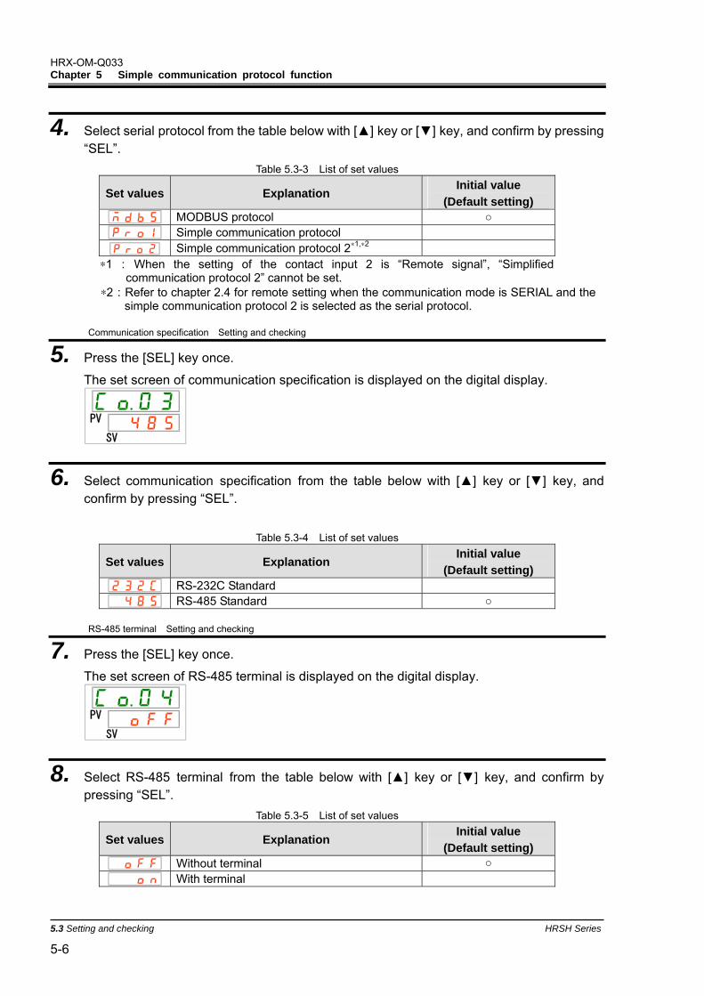
4. Select serial protocol from the table below with [] key or [] key, and confirm by pressing “SEL”.
Table 4.3-3 List of set values
Set values Explanation Initial value
(Default setting) MODBUS protocol Simple communication protocol 1 Simple communication protocol 2∗1
∗1: When the setting of the contact input 2 is “Remote signal”, “Simplified communication protocol 2” cannot be set.
Communication specification Setting and checking
5. Press the [SEL] key once.
The set screen of communication specification is displayed on the digital display.
PV
SV
6. Select communication specification from the table below with [] key or [] key, and confirm by pressing “SEL”.
Table 4.3-4 List of set values
Set values Explanation Initial value
(Default setting) RS-232C standard RS-485 standard
RS-485 terminal Setting and checking
7. Press the [SEL] key once.
The set screen of RS-485 terminal is displayed on the digital display.
PV
SV
8. Select RS-485 terminal from the table below with [] key or [] key, and confirm by pressing “SEL”.
Table 4.3-5 List of set values
Set values Explanation Initial value
(Default setting) Without terminal With terminal
HRX-OM-Q033 Chapter 4 MODBUS communication function
4.3 Setting and checking HRSH Series
4-6
Slave addresses(MODBUS)Setting and checking
9. Press the [SEL] key once.
The set screen of slave address (MODBUS) is displayed on the digital display.
PV
SV
10. Select slave address (MODBUS) from the table below with [] key or [] key, and confirm by pressing “SEL”.
Table 4.3-6 List of set values
Set values Explanation Initial value
(Default setting)
Setting/checking are not available unless the serial protocol setting is MODBUS.
to
Setting of slave address for MODBUS. Set range is 1 to 99.
Communication speed(MODBUS)Setting and checking
11. Press the [SEL] key once.
The set screen of communication speed (MODBUS) is displayed on the digital display.
PV
SV
12. Select communication speed (MODBUS) from the table below with [] key or [] key, and confirm by pressing “SEL”.
Table 4.3-7 List of set values
Set values Explanation Initial value
(Default setting)
Setting/checking are not available unless the serial protocol setting is MODBUS.
9600bps 19200bps
HRX-OM-Q033 Chapter 4 MODBUS communication function
HRSH Series 4.4 Communication sequence 4-7
4.4 Communication sequence Starts with a request message from the customer’s system (host), and
finishes with a response message from the product (slave). This product
operates as a slave. It does not send any requests.
Positive response Based on the request message, reads
register/writes register and returns a positive
response. Negative response Returns a negative message when the received
request message is not normal. Refer to ‘’4.9
Negative response’’. No response No response is returned when there is an error in
“slave address specification” or ”LRC”.
Customer's system(host)
This product(slave)
Request message
Positive response
Request message
Negative response
Request message
No response
10~200ms(Response message)
(Response message)
HRX-OM-Q033 Chapter 4 MODBUS communication function
4.5 Message configuration HRSH Series
4-8
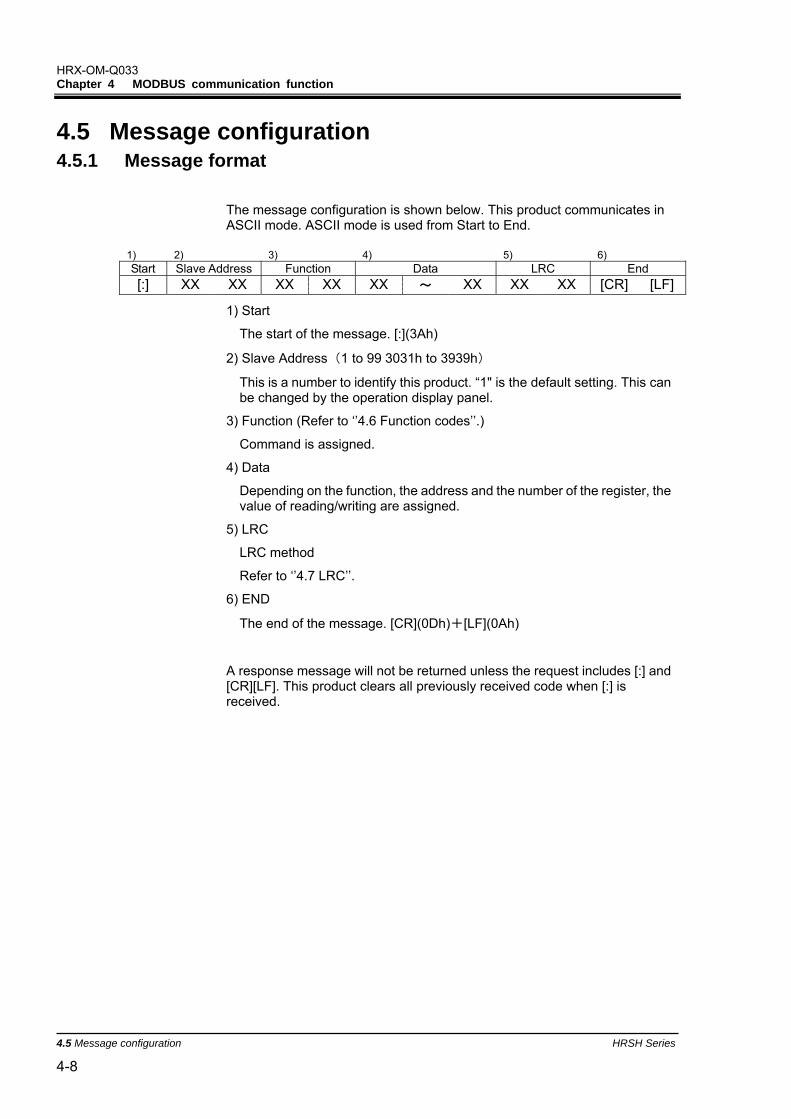
4.5 Message configuration 4.5.1 Message format
The message configuration is shown below. This product communicates in ASCII mode. ASCII mode is used from Start to End.
1) 2) 3) 4) 5) 6) Start Slave Address Function Data LRC End [:] XX XX XX XX XX ~ XX XX XX [CR] [LF]
1) Start
The start of the message. [:](3Ah)
2) Slave Address(1 to 99 3031h to 3939h)
This is a number to identify this product. “1" is the default setting. This can be changed by the operation display panel.
3) Function (Refer to ‘’4.6 Function codes’’.)
Command is assigned.
4) Data
Depending on the function, the address and the number of the register, the value of reading/writing are assigned.
5) LRC
LRC method
Refer to ‘’4.7 LRC’’.
6) END
The end of the message. [CR](0Dh)+[LF](0Ah)
A response message will not be returned unless the request includes [:] and [CR][LF]. This product clears all previously received code when [:] is received.
HRX-OM-Q033 Chapter 4 MODBUS communication function
HRSH Series 4.5 Message configuration 4-9
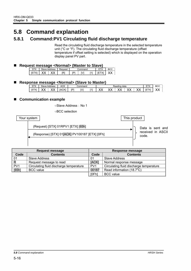
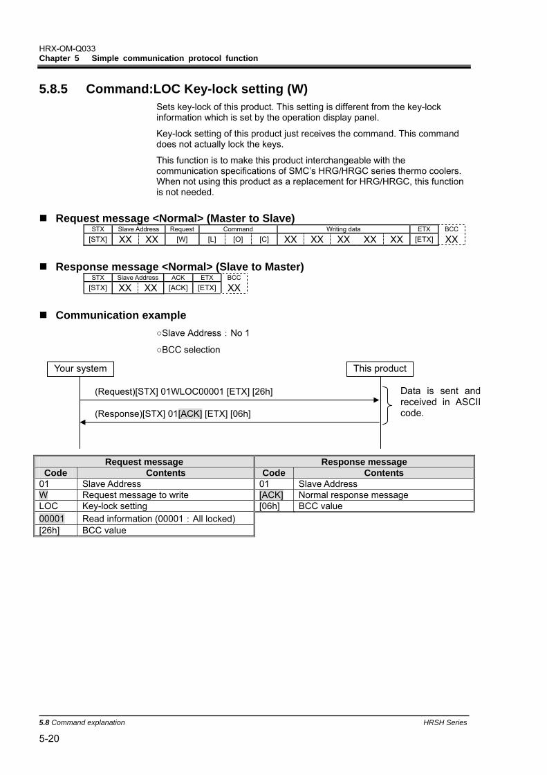
The communication example is expressed in hexadecimal value with [ ]. The actual communication is performed in ASCII code. Refer to the request / response message in this section.
4.5.2 Message example The example shows communication with the conditions below.
01 Slave Address 01 Slave Address 03 Function 03 Function 0000 Head address of specified register 02 Quantity of bytes to read 0001 Quantity of register to read 00EE Information of 0000h (circulating fluid
discharge temperature: 23.8 oC) FB LRC 0C LRC
Request message (Master to Slave) Start Slave Address Function Data LRC End 3A 30 31 30 33 46 42 0D 0A
Read Address Quantity to Read
Hi Lo Hi Lo 30 30 30 30 30 30 30 31
Response message (Slave to Master) Start Slave Address Function Data LRC End 3A 30 31 30 33 30 43 0D 0A
Read Data1 Byte Count
Hi Lo 30 32 30 30 45 45
This product
(Request): 010300000001FB [CR][LF]
(Response): 01030200EE0C [CR][LF]
Your system
Data is sent and received in ASCII code.
HRX-OM-Q033 Chapter 4 MODBUS communication function
4.6 Function codes HRSH Series
4-10
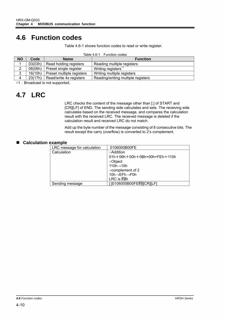
4.6 Function codes Table 4.6-1 shows function codes to read or write register.
Table 4.6-1 Function codes
NO Code Name Function 1 03(03h) Read holding registers Reading multiple registers 2 06(06h) Preset single register Writing registers∗1 3 16(10h) Preset multiple registers Writing multiple registers 4 23(17h) Read/write 4x registers Reading/writing multiple registers
∗1:Broadcast is not supported.
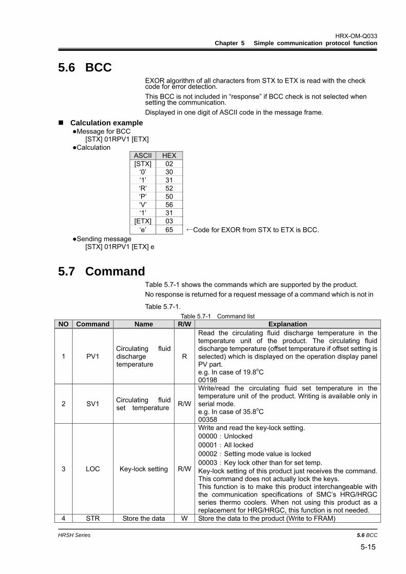
4.7 LRC LRC checks the content of the message other than [:] of START and [CR][LF] of END. The sending side calculates and sets. The receiving side calculates based on the received message, and compares the calculation result with the received LRC. The received message is deleted if the calculation result and received LRC do not match.
Add up the byte number of the message consisting of 8 consecutive bits. The result except the carry (overflow) is converted to 2’s complement.
Calculation example
LRC message for calculation ]0106000B00FE Calculation Addition
01h+06h+00h+0Bh+00h+FEh=110h Object 110h→10h complement of 2 10h→EFh→F0h LRC is F0h
Sending message [:]0106000B00FEF0[CR][LF]
HRX-OM-Q033 Chapter 4 MODBUS communication function
HRSH Series 4.8 Explanation of function codes 4-11
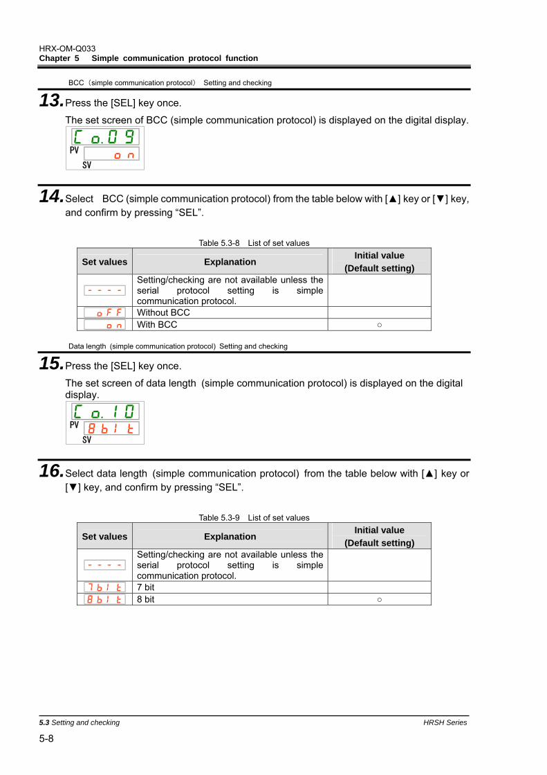
4.8 Explanation of function codes 4.8.1 Function code:03 Reading multiple registers
Register data of assigned points from assigned address is read.
Request message <Normal> (Master to Slave) Start Slave Address Function Data LRC End [:] XX XX [0] [3] XX XX [CR] [LF]
Read Address Quantity to Read
Hi Lo Hi Lo XX XX XX XX XX XX XX XX
Response message<Normal> (Slave to Master)
Start Slave Address Function Data LRC End [:] XX XX [0] [3] XX XX [CR] [LF]
01 Slave Address 01 Slave Address 03 Function 03 Function 0000 Head address of specified register 0E Quantity of bytes to read
0007 Quantity of register to read 00D4 Information of 0000h (circulating fluid discharge temperature)
F5 LRC 0000 Information of 0001h (Reserved)
000D Information of 0002h (circulating fluid discharge pressure)
0000 Information of 0003h (Reserved) 0201 Information of 0004h (Status flag) 0000 Information of 0005h (Alarm flag 1) 0000 Information of 0006h (Alarm flag 2) 0A LRC
01 Slave Address 01 Slave Address 06 Function 06 Function 000C Address of specified register 000C Address of register to write 0001 Information written to 000Ch (Stop flag) 0001 Information of register to write EC LRC EC LRC
This product
(Request):0106000C0001EC [CR][LF]
(Response):0106000C0001EC [CR][LF]
Your system
Data is sent and received in ASCII code.
HRX-OM-Q033 Chapter 4 MODBUS communication function
HRSH Series 4.8 Explanation of function codes 4-13
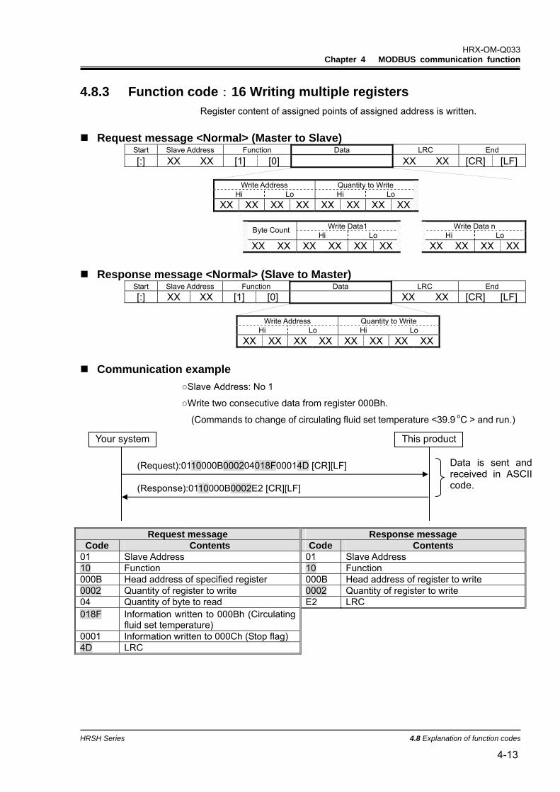
4.8.3 Function code:16 Writing multiple registers Register content of assigned points of assigned address is written.
Request message <Normal> (Master to Slave)
Start Slave Address Function Data LRC End [:] XX XX [1] [0] XX XX [CR] [LF]
Write Address Quantity to Write
Hi Lo Hi Lo XX XX XX XX XX XX XX XX
Write Data1 Write Data n Byte Count
Hi Lo Hi Lo XX XX XX XX XX XX XX XX XX XX
Response message <Normal> (Slave to Master)
Start Slave Address Function Data LRC End [:] XX XX [1] [0] XX XX [CR] [LF]
Write Address Quantity to Write
Hi Lo Hi Lo XX XX XX XX XX XX XX XX
Communication example
Slave Address: No 1
Write two consecutive data from register 000Bh.
(Commands to change of circulating fluid set temperature <39.9 oC > and run.)
01 Slave Address 01 Slave Address 10 Function 10 Function 000B Head address of specified register 000B Head address of register to write 0002 Quantity of register to write 0002 Quantity of register to write 04 Quantity of byte to read E2 LRC 018F Information written to 000Bh (Circulating
fluid set temperature)
0001 Information written to 000Ch (Stop flag) 4D LRC
(Request):0110000B000204018F00014D [CR][LF]
(Response):0110000B0002E2 [CR][LF]
Your system This product
Data is sent and received in ASCII code.
HRX-OM-Q033 Chapter 4 MODBUS communication function
4.8 Explanation of function codes HRSH Series
4-14
4.8.4 Function code:23 Reading/writing multiple registers Register content of assigned points of assigned address is read. Write the register data from the specified address with specified points simultaneously.
Request message <Normal> (Master to Slave)
Start Slave Address Function Data LRC End [:] XX XX [1] [7] XX XX [CR] [LF]
Read Address Quantity to Read Write Address Quantity to Write
Hi Lo Hi Lo Hi Lo Hi Lo XX XX XX XX XX XX XX XX XX XX XX XX XX XX XX XX
Write Data1 Write Data n Byte Count
Hi Lo Hi Lo XX XX XX XX XX XX XX XX XX XX
Response message <Normal> (Slave to Master)
Start Slave Address Function Data LRC End [:] XX XX [1] [7] XX XX [CR] [LF]
Read Data1 Read Data n Byte Count
Hi Lo Hi Lo XX XX XX XX XX XX XX XX XX XX
HRX-OM-Q033 Chapter 4 MODBUS communication function
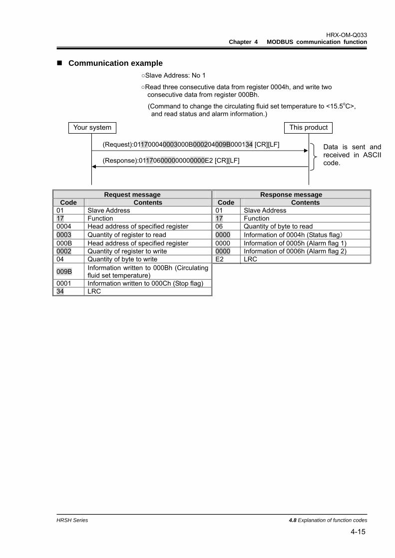
HRSH Series 4.8 Explanation of function codes 4-15
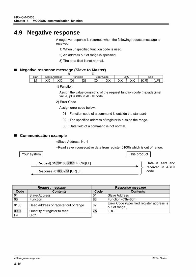
Communication example Slave Address: No 1
Read three consecutive data from register 0004h, and write two consecutive data from register 000Bh.
(Command to change the circulating fluid set temperature to <15.5oC>, and read status and alarm information.)
01 Slave Address 01 Slave Address 17 Function 17 Function 0004 Head address of specified register 06 Quantity of byte to read 0003 Quantity of register to read 0000 Information of 0004h (Status flag) 000B Head address of specified register 0000 Information of 0005h (Alarm flag 1) 0002 Quantity of register to write 0000 Information of 0006h (Alarm flag 2) 04 Quantity of byte to write E2 LRC
009B Information written to 000Bh (Circulating fluid set temperature)
0001 Information written to 000Ch (Stop flag) 34 LRC
01 Slave Address 01 Slave Address 03 Function 83 Function (03h+80h)
0100 Head address of register out of range 02 Error Code (Specified register address is out of range.)
0007 Quantity of register to read 7A LRC F4 LRC
This product
(Request):010301000007F4 [CR][LF]
(Response):0183027A [CR][LF]
Your system
Data is sent and received in ASCII code.
HRX-OM-Q033 Chapter 4 MODBUS communication function
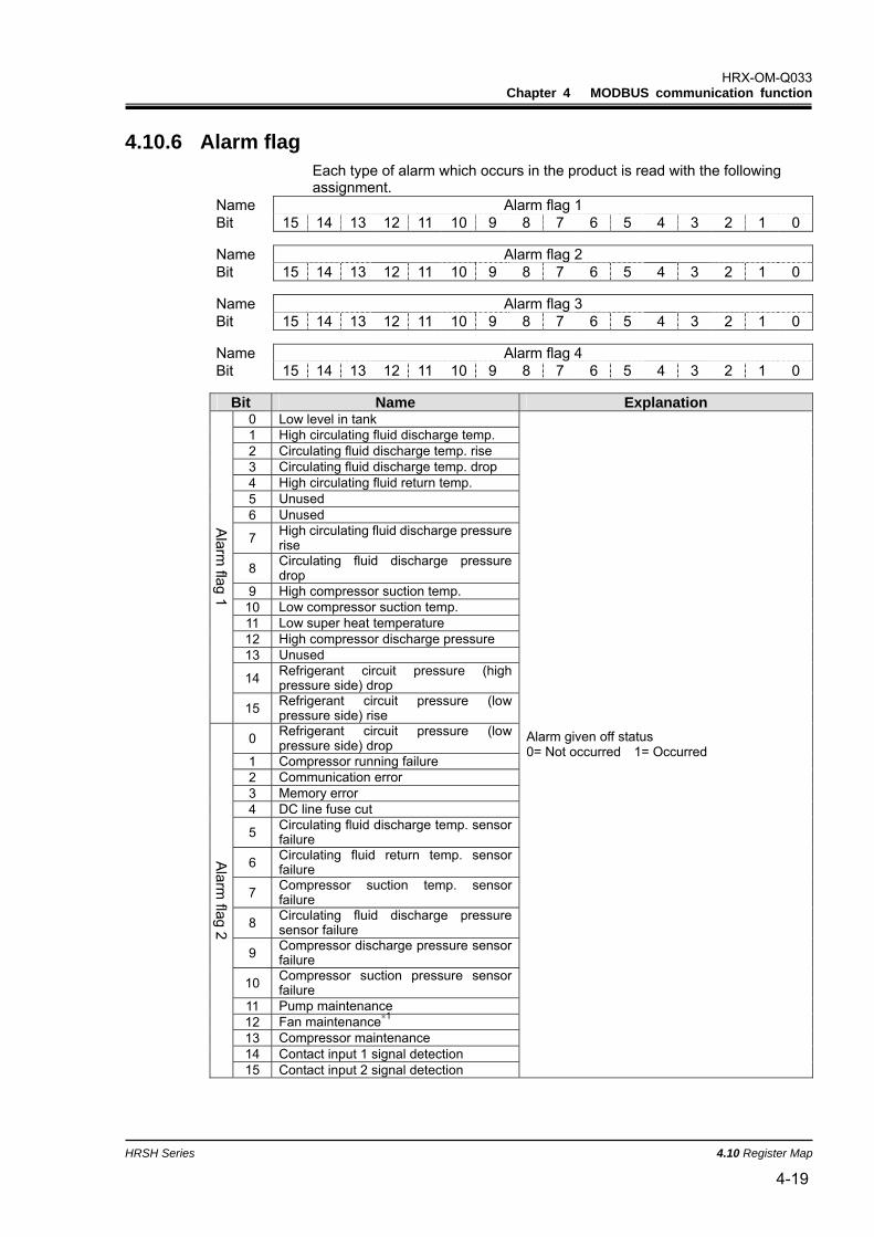
HRSH Series 4.10 Register Map 4-17
4.10 Register Map
Bit Format Address
15 14 13 12 11 10 9 8 7 6 5 4 3 2 1 0R/W
-110.0 to 150.0oC = FBB4h to 5DCh (0.1 oC /dig)0000h Circulating fluid discharge temperature -166.0 to 302.0 oF = F984h to BCCh (0.1 oF /dig)
0001h Circulating fluid flow rate 0.0 to 195.0L/min = 0h to 79Eh (0.1L/min/dig)
0.00 to 3.00MPa = 0h to 12Ch (0.01MPa/dig) 0002h Circulating fluid discharge pressure 0 to 435PSI = 0h to 1B3h (1PSI/dig)
0003h Circulating fluid electric conductivity 2.0 to 48.0 microS/cm = 14h to 1E0 (0.1microS/cm/dig)
0004h Status flag
0005h Alarm flag 1
0006h Alarm flag 2
0007h Alarm flag 3
0008h Alarm flag 4
0009h Reserved
000Ah Reserved
R
5.0 to 35.0 oC = 32h to 15Eh (0.1 oC /dig) 000Bh Circulating fluid set temperature 41.0 to 95.0 oF = 3B6h to 410h (0.1 oF /dig)
000Ch Reserved ∗1
000Dh Reserved
000Eh Reserved
000Fh Reserved
R/W
∗1:Commands to run
4.10.1 Circulating fluid discharge temperature Read the circulating fluid discharge temperature in the selected temperature unit (°C or °F). Read the circulating fluid discharge temperature which is displayed on the operation display panel PV. (Offset temperature is displayed if offset function is set).
4.10.3 Circulating fluid discharge pressure Read the circulating fluid discharge pressure in the selected pressure unit (MPa or PSI).
4.10.4 Circulating fluid electric conductivity Read the circulating fluid electric conductivity. In case of [SE.19 Electric conductivity sensor setting] is off, value is 0 [microS/cm].
HRX-OM-Q033 Chapter 4 MODBUS communication function
4.10 Register Map HRSH Series
4-18
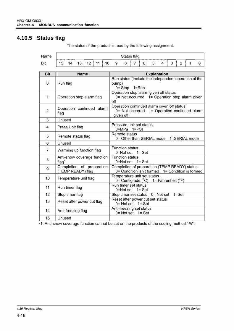
4.10.5 Status flag The status of the product is read by the following assignment.
Name Status flag
Bit 15 14 13 12 11 10 9 8 7 6 5 4 3 2 1 0
Bit Name Explanation
0 Run flag Run status (Include the independent operation of the pump) 0= Stop 1=Run
1 Operation stop alarm flag Operation stop alarm given off status 0= Not occurred 1= Operation stop alarm given off
2 Operation continued alarm flag
Operation continued alarm given off status 0= Not occurred 1= Operation continued alarm given off
3 Unused
4 Press Unit flag Pressure unit set status 0=MPa 1=PSI
5 Remote status flag Remote status 0= Other than SERIAL mode 1=SERIAL mode
6 Unused
7 Warming up function flag Function status 0=Not set 1= Set
8 Anti-snow coverage function flag∗1
Function status 0=Not set 1= Set
9 Completion of preparation (TEMP READY) flag
Completion of preparation (TEMP READY) status 0= Condition isn’t formed 1= Condition is formed
10 Temperature unit flag Temperature unit set status 0= Centigrade (oC) 1= Fahrenheit (oF)
11 Run timer flag Run timer set status 0=Not set 1= Set
12 Stop timer flag Stop timer set status 0= Not set 1=Set
13 Reset after power cut flag Reset after power cut set status 0= Not set 1= Set
14 Anti-freezing flag Anti-freezing set status 0= Not set 1= Set
15 Unused
∗1: Anti-snow coverage function cannot be set on the products of the cooling method ‘-W’.
HRX-OM-Q033 Chapter 4 MODBUS communication function
HRSH Series 4.10 Register Map 4-19
4.10.6 Alarm flag Each type of alarm which occurs in the product is read with the following assignment.
Name Alarm flag 1 Bit 15 14 13 12 11 10 9 8 7 6 5 4 3 2 1 0
Name Alarm flag 2 Bit 15 14 13 12 11 10 9 8 7 6 5 4 3 2 1 0
Name Alarm flag 3 Bit 15 14 13 12 11 10 9 8 7 6 5 4 3 2 1 0
Name Alarm flag 4 Bit 15 14 13 12 11 10 9 8 7 6 5 4 3 2 1 0
Bit Name Explanation
0 Low level in tank 1 High circulating fluid discharge temp. 2 Circulating fluid discharge temp. rise 3 Circulating fluid discharge temp. drop 4 High circulating fluid return temp. 5 Unused 6 Unused
7 High circulating fluid discharge pressurerise
8 Circulating fluid discharge pressure drop
9 High compressor suction temp. 10 Low compressor suction temp. 11 Low super heat temperature 12 High compressor discharge pressure 13 Unused
14 Refrigerant circuit pressure (high pressure side) drop
Alarm given off status 0= Not occurred 1= Occurred
∗1: These alarms do not occur on the product of the cooling method ‘-W’. ∗2: These alarms do not occur on the product of the power specification '-20'. ∗3: These alarms do not occur on the product of the cooling method ‘-A’.
・The current alarm flag bit assignment will be changed in the future due to the addition of optional functions.
・Unused bit is fixed to 0.
HRX-OM-Q033 Chapter 4 MODBUS communication function
HRSH Series 4.10 Register Map 4-21
4.10.7 Circulating fluid set temperature The circulating fluid set temperature can be set by specifying the circulating fluid set temperature with the selected temperature unit (°C or °F) during SERIAL mode.
If the temperature exceeds the upper limit of the circulating fluid set temperature range, the circulating fluid set temperature is changed to the upper limit value. If it is lower than the lower limit, the circulating fluid set temperature is changed to the lower limit value.
4.10.8 Operation Start Command The operation can be controlled by sending the operation start command during SERIAL mode.
0=Run stop 1=Run start
HRX-OM-Q033 Chapter 4 MODBUS communication function
4.10 Register Map HRSH Series
4-22
HRX-OM-Q033 Chapter 5 Simple communication protocol function
HRSH Series 5.1 Precautions for communication 5-1
Chapter 5 Simple communication protocol function Data can be read / written by this communication protocol. This protocol complies with SMC thermo-cooler HRG, HRGC series.
This communication has the following features.
・Sets and reads the circulating fluid set temperature.
・Reads the circulating fluid discharge temperature.
5.1 Precautions for communication 5.1.1 Precautions after wiring and before communication
Check or set each communication setting by the operation display panel.
・The communication specification shall be the customer’s communication standard.
・The serial protocol shall be the simple communication protocol 1 or 2.
Simple communication protocol 1:Operation display panel controls the start and stop of the product.
Simple communication protocol 2:Controls the start and stop of the product remotely.
Refer to chapter 2.4 for remote setting when this protocol is selected.
・The communication mode shall be the SERIAL mode.
Other modes can perform reading, but only SERIAL mode can perform writing of values.
Check or set the communication parameters using the operation display panel.
Check or set the communication speed, the presence of BCC, data length, parity check, stop bit length, response delay time, and communication range (RO or RW) to synchronize the product with the host computer (master) prepared by the customer.
Check the slave address of this product.
No response is returned when a request message is sent from a slave address other than those set in the product.
HRX-OM-Q033 Chapter 5 Simple communication protocol function
5.1 Precautions for communication HRSH Series
5-2
5.1.2 Precautions for communicating Check the data digit number and the decimal point location when requesting to write the set value.
Allow a suitable interval between requests.
To send request messages in series, wait for 100msec. or longer after receiving a response message from the product before sending the next message.
No response is returned for a request message of a command which is not supported by the product.
Retry (resend request message).
The response may not be returned due to noise. If no message is returned after 1sec. of sending a request message, resend the request message.
If necessary send a read request message to check if it was written correctly.
Message to notify the completion of the process is returned when the action for the written request message is completed.
5.1.3 Precautions after the completion of the communication Send the data storage request (STR) if necessary.
Data which is set by communication is stored in RAM. Set values stored in RAM are deleted when the power supplied to the product is cut. When the power is supplied again, operation starts with the values set before communication (values stored in FRAM of the product).
Store the values set by communication in FRAM (rewrite FRAM) by sending a data storage request message (STR) before cutting the power supply to the product.
Please check how many times it is possible to write to FRAM, and avoid unnecessary rewriting of the data during communication
HRX-OM-Q033 Chapter 5 Simple communication protocol function
HRSH Series 5.2 Communication specification 5-3
5.2 Communication specification
Table 5.2-1 Communication specification of simple communication protocol Item Specification
Standard Select from EIA RS-485/RS-232C Communication speed Select from 1200bps/2400bps/4800bps/9600bps/19200bps Data・bit length Select from 7bit/8bit Stop・bit length Select from 1bit、2bit Parity Select from without parity ,odd number ,even number Letter code ASCII mode Slave address set range Select from 1 to 99 Response delay time setting Select from 0 to 250[msec]
Communication range RO(Can read data only), Select from RW(can read and write data)
BCC Select from with BCC , without BCC
Error check EXOR algorithm of all data from STX to ETX is read only when BCC is selected.
:Default setting
HRX-OM-Q033 Chapter 5 Simple communication protocol function
5.3 Setting and checking HRSH Series
5-4
5.3 Setting and checking 5.3.1 Setting and checking items
The table below explains the setting items of the simple communication protocol function and the initial values.
Table 5.3-1 Communication setting items
Display Item Contents Initial value Communication mode Sets communication mode. LOC Serial protocol Sets serial communication protocol. MDBS
Communication specification
Sets standard of the serial communication. 485
RS-485 terminal Sets terminal of RS-485. OFF
Slave address (Simple communication protocol)
Sets slave address of simple communication protocol. [----] is displayed when the setting of serial protocol is not simple communication protocol.
---- (1)
Communication speed (Simple communication protocol)
Sets communication speed of simple communication protocol. [----] is displayed when the setting of serial protocol is not simple communication protocol.
---- (9.6)
BCC (Simple communication protocol)
Sets error detection code of communication of simple communication protocol. [----] is displayed when the setting of serial protocol is not simple communication protocol.
---- (ON)
Data length (Simple communication protocol)
Sets data length. [----] is displayed when the setting of serial protocol is not simple communication protocol. ---- (8BIT)
Parity check (Simple communication protocol)
Sets parity check. [----] is displayed when the setting of serial protocol is not simple communication protocol. ---- (NON)
Stop bit length (Simple communication protocol)
Sets bit length. [----] is displayed when the setting of serial protocol is not simple communication protocol. ---- (2BIT)
Response delay time (Simple communication protocol)
Sets time to delay the response message of simple communication protocol. [----] is displayed when the setting of serial protocol is not simple communication protocol.
---- (0)
Communication range (Simple communication protocol)
Sets communication range of simple communication protocol. [----] is displayed when the setting of serial protocol is not simple communication protocol.
---- (RW)
HRX-OM-Q033 Chapter 5 Simple communication protocol function
HRSH Series 5.3 Setting and checking 5-5
5.3.2 Setting and checking
Communication mode Setting and checking
1. Press and hold the [MENU] key for 2 sec.
Repeat pressing the key until the setting screen for communication mode [ ] appears on the digital display.
PV
SV
PV
SV
PV
SV
PV
SV
PV
SV
2. Select “SER” from the table below with the [] key, and confirm with “SEL”.
PV
SV Table 5.3-2 List of set values
Set values Explanation Initial value
(Default setting) Sets LOCAL mode Sets DIO mode Sets SERIAL mode∗1
∗1 : If the serial protocol is “Simple communication protocol 2” and the contact input 1 is “external switch signal” or contact input 2 is “remote signal”, “SERIAL mode” cannot be set.
Serial protocol Setting and checking
3. Press the [SEL] key once.
The set screen of serial protocol is displayed on the digital display.
PV
SV
[MENU] Press and
hold
[MENU] Press and
hold
[MENU] Press and
hold
[MENU] Press and
hold
HRX-OM-Q033 Chapter 5 Simple communication protocol function
5.3 Setting and checking HRSH Series
5-6
4. Select serial protocol from the table below with [] key or [] key, and confirm by pressing “SEL”.
Table 5.3-3 List of set values
Set values Explanation Initial value
(Default setting) MODBUS protocol Simple communication protocol
Simple communication protocol 2∗1,∗2
∗1 : When the setting of the contact input 2 is “Remote signal”, “Simplified communication protocol 2” cannot be set.
∗2 : Refer to chapter 2.4 for remote setting when the communication mode is SERIAL and the simple communication protocol 2 is selected as the serial protocol.
Communication specification Setting and checking
5. Press the [SEL] key once.
The set screen of communication specification is displayed on the digital display.
PV
SV
6. Select communication specification from the table below with [] key or [] key, and confirm by pressing “SEL”.
Table 5.3-4 List of set values
Set values Explanation Initial value
(Default setting) RS-232C Standard RS-485 Standard
RS-485 terminal Setting and checking
7. Press the [SEL] key once.
The set screen of RS-485 terminal is displayed on the digital display.
PV
SV
8. Select RS-485 terminal from the table below with [] key or [] key, and confirm by pressing “SEL”.
Table 5.3-5 List of set values
Set values Explanation Initial value
(Default setting) Without terminal With terminal
HRX-OM-Q033 Chapter 5 Simple communication protocol function
HRSH Series 5.3 Setting and checking 5-7
Slave addresses(simple communication protocol) Setting and checking
9. Press the [SEL] key 3 times.
The set screen of slave address (simple communication protocol) is displayed on the digital display.
PV
SV
10. Select slave address (simple communication protocol) from the table below with [] key or [] key, and confirm by pressing “SEL”.
Table 5.3-6 List of set values
Set values Explanation Initial value
(Default setting) Setting/checking are not available unless the serial protocol setting is simple communication protocol.
to Setting of slave address for simple communication protocol. Set range is 1 to 99.
Communication speed (simple communication protocol) Setting and checking
11. Press the [SEL] key once.
The set screen of communication speed (simple communication protocol) is displayed on the digital display.
PV
SV
12. Select communication speed (simple communication protocol) from the table below with [] key or [] key, and confirm by pressing “SEL”.
Table 5.3-7 List of set values
Set values Explanation Initial value
(Default setting) Setting/checking are not available unless the serial protocol setting is simple communication protocol.
1200bps 2400bps 4800bps 9600bps
19200bps
HRX-OM-Q033 Chapter 5 Simple communication protocol function
5.3 Setting and checking HRSH Series
5-8
BCC(simple communication protocol) Setting and checking
13. Press the [SEL] key once.
The set screen of BCC (simple communication protocol) is displayed on the digital display.
PV
SV
14. Select BCC (simple communication protocol) from the table below with [] key or [] key, and confirm by pressing “SEL”.
Table 5.3-8 List of set values
Set values Explanation Initial value
(Default setting)
Setting/checking are not available unless the serial protocol setting is simple communication protocol.
Without BCC With BCC
Data length (simple communication protocol) Setting and checking
15. Press the [SEL] key once.
The set screen of data length (simple communication protocol) is displayed on the digital display.
PV
SV
16. Select data length (simple communication protocol) from the table below with [] key or [] key, and confirm by pressing “SEL”.
Table 5.3-9 List of set values
Set values Explanation Initial value
(Default setting)
Setting/checking are not available unless the serial protocol setting is simple communication protocol.
7 bit 8 bit
HRX-OM-Q033 Chapter 5 Simple communication protocol function
HRSH Series 5.3 Setting and checking 5-9
Parity check (simple communication protocol) Setting and checking
17. Press the [SEL] key once.
The set screen of parity check (simple communication protocol) is displayed on the digital display.
PV
SV
18. Select parity check (simple communication protocol) from the table below with [] key or [] key, and confirm by pressing “SEL”.
Table 5.3-10 List of set values
Set values Explanation Initial value
(Default setting) Setting/checking are not available unless the serial protocol setting is simple communication protocol.
None Odd number Even number
Stop bit(simple communication protocol) Setting and checking
19. Press the [SEL] key once.
The set screen of stop bit (simple Communication protocol) is displayed on the digital display.
PV
SV
20. Select stop bit (simple communication protocol) from the table below with [] key or [] key, and confirm by pressing “SEL”.
Table 5.3-11 List of set values
Set values Explanation Initial value
(Default setting) Setting/checking are not available unless the serial protocol setting is simple communication protocol.
1 bit 2 bit
HRX-OM-Q033 Chapter 5 Simple communication protocol function
5.3 Setting and checking HRSH Series
5-10
Response delay time (simple communication protocol) Setting and checking
21. Press the [SEL] key once.
The set screen of response delay time (simple communication protocol) is displayed on the digital display.
PV
SV
22. Select response delay time (simple communication protocol) from the table below with [] key or [] key, and confirm by pressing “SEL”.
Table 5.3-12 List of set values
Set values Explanation Initial value
(Default setting)
Setting/checking are not available unless the serial protocol setting is simple communication protocol.
to
Setting of response delay time Set range is 0 to 250m sec.
Communication range (simple communication protocol) Setting and checking
23. Press the [SEL] key once.
The set screen of communication range (simple communication protocol) is displayed on the digital display.
PV
SV
24. Select communication range (simple communication protocol) from the table below with [] key or [] key, and confirm by pressing “SEL”.
Table 5.3-13 List of set values
Set values Explanation Initial value
(Default setting)
Setting/checking are not available unless the serial protocol setting is simple communication protocol.
Only reading is available Reading and writing are available
HRX-OM-Q033 Chapter 5 Simple communication protocol function
HRSH Series 5.4 Communication sequence 5-11
5.4 Communication sequence Starts with a request message from the customer’s system (host), and finishes with a response message from the product (slave). This product operates as a slave. It does not send any requests.
Positive response Based on the request message, reads/writes return a positive response. . Negative response Returns a negative message when the
received request message is not normal.
Refer to “5.9 Negative response’’. No response No response is returned when the slave address is specified or a command which is not supported is received.
Customer's equipment side(Master)
Thermo-chiller side(Slave)
Request message
Positive response
Request message
Negative response
Request message
No response
0 to 250ms(Responsedelay time)
(Negative message)
(Negative message)
10 to 200ms
HRX-OM-Q033 Chapter 5 Simple communication protocol function
5.5 Message configuration HRSH Series
5-12
5.5 Message configuration The message configuration is shown in the following. The explanation of data in message is shown in the Table 5.5-1. This product communicates in ASCII mode. ASCII mode is used from STX to ETX. Hexadecimal value is used for BCC.
5.5.1 Message format
1) Request message format 1-1) Request message (Request to read)
STX Slave Address Request Command ETX BCC[STX] XX XX [R] XX XX XX [ETX] XX
1-2) Request message (Request to write)
STX Slave Address Request Command Writing data ETX BCC[STX] XX XX [W] XX XX XX XX XX XX XX XX [ETX] XX
1-3) Request message (Request to store the data)
STX Slave Address Request Command ETX BCC[STX] XX XX [W] XX XX XX [ETX] XX
2) Response message format
2-1) Response message (Normal response to request to write) STX Slave Address ACK Command Reading data ETX BCC
[STX] XX XX [ACK] XX XX XX XX XX XX XX XX [ETX] XX
2-2) Response message (Normal response to request to write or store the data) STX Slave Address ACK ETX BCC
[STX] XX XX [ACK] [ETX] XX
2-3) Response message (Response when a receiving error occurred) STX Slave Address NAK ETX BCC
[STX] XX XX [NAK] XX [ETX] XX Response is not returned unless STX and ETX (BCC) are included in the request. This product clears all previously received code when STX is received.
Exception code
HRX-OM-Q033 Chapter 5 Simple communication protocol function
HRSH Series 5.5 Message configuration 5-13
Table 5.5-1 Format data NO Item Explanation
1 STX(02h) Start text The code to specify the head of the message. Added to the head of the characters to be sent.
2 ETX(03h) End text The code to specify the end of the message. Added to the end of the characters to be sent. Other than BCC.
3 Slave Address
Slave address which is set to each product. Can be changed by setting. The address to identify the device.
4 Request Request identifier. R (reading) or W (writing) 5 Command Command to reading or writing.
6 Writing Reading
To request writing, write the data in this area to the object data. To request reading, set the object data in this area.
7 BCC
EXOR algorithm of all characters from STX to ETX is read with the check code for error detection. This code (BCC) is not included in “response” if BCC check is not selected when setting the communication.
8 ACK(06h) Acknowledge code. This is included in the response from the product when there is no error in the received request.
9 NAK(15h) Negative acknowledge code. This is included in the response from the product when there is an error in the received request.
10 Exception code
Error content is included in the response when there is an error in the received request. Refer to the table below for exception codes.
Exception code Exception
0 Equipment malfunction Memory error
1 Out of set range Value data is out of “set range specified independently by set parameter”
2
Setting not allowed. Changing of requested communication parameter is prohibited. Or communication parameter to read does not exist. Writing of the communication mode is requested while the communication mode change is set to RO (read only) Writing to PV (measured value) is requested.
3
Abnormal code ASCII code other than numerical data is requested (specified) to the location for numerical data. ASCII code other than “0” or”-” is requested (specified) to the location for symbol.
∗1 : Exception code “0” is included in the response regardless of the presence of the request error because memory error is present.
∗2 : The exception with the highest number is included in the response when two or more errors have occurred.
HRX-OM-Q033 Chapter 5 Simple communication protocol function
5.5 Message configuration HRSH Series
5-14
The communication example is expressed in hexadecimal value with [ ]. The actual communication is performed with ASCII code. Refer to the request / response message in this section.
5.5.2 Message example The example shows communication with the conditions below.
01 Slave Address 01 Slave Address R Request message to read [ACK] Normal response message
PV1 Circulating fluid discharge temperature PV1 Circulating fluid discharge temperature [65h] BCC value 00187 Read information
[0Fh] BCC value
Request message (Master to Slave) STX Slave
Address Request Command ETX BCC
02 30 31 52 50 56 31 03 65
Response message (Slave to Master) STX Slave
Address ACK Command Reading data ETX BCC
02 30 31 06 50 56 31 30 30 31 38 37 03 0F
This product
(Request): [STX] 01RPV1 [ETX] [65h]
(Response): [STX] 01[ACK] PV100187 [ETX] [0Fh]
Your system
Data is sent and received in ASCII code.
HRX-OM-Q033 Chapter 5 Simple communication protocol function
HRSH Series 5.6 BCC 5-15
5.6 BCC EXOR algorithm of all characters from STX to ETX is read with the check code for error detection. This BCC is not included in “response” if BCC check is not selected when setting the communication. Displayed in one digit of ASCII code in the message frame.
Calculation example Message for BCC
[STX] 01RPV1 [ETX] Calculation
ASCII HEX [STX] 02
‘0’ 30 ‘1’ 31 ‘R’ 52 ‘P’ 50 ‘V’ 56 ‘1’ 31
[ETX] 03 ‘e’ 65 ←Code for EXOR from STX to ETX is BCC.
Sending message [STX] 01RPV1 [ETX] e
5.7 Command
Table 5.7-1 shows the commands which are supported by the product. No response is returned for a request message of a command which is not in
Table 5.7-1. Table 5.7-1 Command list
NO Command Name R/W Explanation
1 PV1 Circulating fluiddischarge temperature
R
Read the circulating fluid discharge temperature in the temperature unit of the product. The circulating fluid discharge temperature (offset temperature if offset setting is selected) which is displayed on the operation display panel PV part. e.g. In case of 19.8oC 00198
2 SV1 Circulating fluidset temperature R/W
Write/read the circulating fluid set temperature in the temperature unit of the product. Writing is available only in serial mode. e.g. In case of 35.8oC 00358
3 LOC Key-lock setting R/W
Write and read the key-lock setting. 00000:Unlocked 00001:All locked 00002:Setting mode value is locked 00003:Key lock other than for set temp. Key-lock setting of this product just receives the command. This command does not actually lock the keys. This function is to make this product interchangeable with the communication specifications of SMC’s HRG/HRGC series thermo coolers. When not using this product as a replacement for HRG/HRGC, this function is not needed.
4 STR Store the data W Store the data to the product (Write to FRAM)
HRX-OM-Q033 Chapter 5 Simple communication protocol function
5.8 Command explanation HRSH Series
5-16
5.8 Command explanation 5.8.1 Command:PV1 Circulating fluid discharge temperature
Read the circulating fluid discharge temperature in the selected temperature unit (°C or °F). The circulating fluid discharge temperature (offset temperature if offset setting is selected) which is displayed on the operation display panel PV part.
Request message <Normal> (Master to Slave)
STX Slave Address Request Command ETX BCC[STX] XX XX [R] [P] [V] [1] [ETX] XX
Response message <Normal> (Slave to Master)
STX Slave Address ACK Command Reading data ETX BCC[STX] XX XX [ACK] [P] [V] [1] XX XX XX XX XX [ETX] XX
01 Slave Address 01 Slave Address R Request message to read [ACK] Normal response message PV1 Circulating fluid discharge temperature PV1 Circulating fluid discharge temperature [65h] BCC value 00187 Read information (18.7oC) [0Fh] BCC value
This product
(Request) [STX] 01RPV1 [ETX] [65h]
(Response) [STX] 01[ACK] PV100187 [ETX] [0Fh]
Your system
Data is sent and received in ASCII code.
HRX-OM-Q033 Chapter 5 Simple communication protocol function
HRSH Series 5.8 Command explanation 5-17
5.8.2 Command:SV1 Circulating fluid set temperature (R) Read the circulating fluid set temperature in the selected temperature unit (°C or °F).
Request message <Normal> (Master to Slave)
STX Slave Address Request Command ETX BCC[STX] XX XX [R] [S] [V] [1] [ETX] XX
Response message <Normal> (Slave to Master)
STX Slave Address ACK Command Reading data ETX BCC[STX] XX XX [ACK] [S] [V] [1] XX XX XX XX XX [ETX] XX
01 Slave Address 01 Slave Address R Request message to read [ACK] Normal response message SV1 Circulating fluid set temperature SV1 Circulating fluid set temperature [66h] BCC value 00258 Read information (25.8oC) [0Dh] BCC value
Your system This product
(Request) [STX] 01RSV1 [ETX] [66h]
(Response) [STX] 01[ACK] SV100258 [ETX] [0Dh]
Data is sent and received in ASCII code.
HRX-OM-Q033 Chapter 5 Simple communication protocol function
5.8 Command explanation HRSH Series
5-18
5.8.3 Command:SV1 Circulating fluid set temperature (W) Read the circulating fluid set temperature in the selected temperature unit (°C or °F).
Request message <Normal> (Master to Slave)
STX Slave Address Request Command Writing data ETX BCC[STX] XX XX [W] [S] [V] [1] XX XX XX XX XX [ETX] XX
Response message <Normal> (Slave to Master)
STX Slave Address ACK ETX BCC[STX] XX XX [ACK] [ETX] XX
01 Slave Address 01 Slave Address W Request message to write [ACK] Normal response message SV1 Circulating fluid set temperature [06h] BCC value 00258 Write information (25.8 oC) [5Ch] BCC value
Your system This product
(Request)[STX] 01WSV100258 [ETX] [5Ch]
(Response)[STX] 01[ACK] [ETX] [06h]
Data is sent and received in ASCII code.
HRX-OM-Q033 Chapter 5 Simple communication protocol function
HRSH Series 5.8 Command explanation 5-19
5.8.4 Command:LOC Key-lock setting (R) Read the key-lock condition set in 5.8.5 ‘’Command: LOC’’.
It is different from the key-lock information which is set by the operation display panel.
Request message <Normal> (Master to Slave)
STX Slave Address Request Command ETX BCC[STX] XX XX [R] [L] [O] [C] [ETX] XX
Response message <Normal> (Slave to Master)
STX Slave Address ACK Command Reading data ETX BCC[STX] XX XX [ACK] [L] [O] [C] XX XX XX XX XX [ETX] XX
01 Slave Address 01 Slave Address R Request message to read [ACK] Normal response message LOC Key-lock setting LOC Key-lock setting [12h] BCC value 00001 Read information(00001:All locked) [77h] BCC value
This product
(Request)[STX]01RLOC[ETX][12h]
(Response)[STX]01[ACK]LOC00001[ETX][77h]
Your system
Data is sent and received in ASCII code.
HRX-OM-Q033 Chapter 5 Simple communication protocol function
5.8 Command explanation HRSH Series
5-20
5.8.5 Command:LOC Key-lock setting (W) Sets key-lock of this product. This setting is different from the key-lock information which is set by the operation display panel.
Key-lock setting of this product just receives the command. This command does not actually lock the keys.
This function is to make this product interchangeable with the communication specifications of SMC’s HRG/HRGC series thermo coolers. When not using this product as a replacement for HRG/HRGC, this function is not needed.
Request message <Normal> (Master to Slave)
STX Slave Address Request Command Writing data ETX BCC[STX] XX XX [W] [L] [O] [C] XX XX XX XX XX [ETX] XX
Response message <Normal> (Slave to Master)
STX Slave Address ACK ETX BCC[STX] XX XX [ACK] [ETX] XX
01 Slave Address 01 Slave Address W Request message to write [ACK] Normal response message LOC Key-lock setting [06h] BCC value 00001 Read information (00001:All locked) [26h] BCC value
Your system This product
(Request)[STX] 01WLOC00001 [ETX] [26h]
(Response)[STX] 01[ACK] [ETX] [06h]
Data is sent and received in ASCII code.
HRX-OM-Q033 Chapter 5 Simple communication protocol function
HRSH Series 5.8 Command explanation 5-21
5.8.6 Command:STR Saves data (W) Store the circulating fluid set temperature set in 5.8.3 ‘’Command:SV1 Circulating fluid set temperature’’. Key-lock set data which is set in 5.8.5 ‘’Command:LOC Key-lock setting (W)’’ is not the object to store.
Request message <Normal> (Master to Slave)
STX Slave Address Request Command ETX BCC[STX] XX XX [W] [S] [T] [R] [ETX] XX
Response message <Normal> (Slave to Master)
STX Slave Address ACK ETX BCC[STX] XX XX [ACK] [ETX] XX
01 Slave Address 01 Slave Address W Request message to write [ACK] Normal response message STR Saves data [06h] BCC value [02h] BCC value
Your system This product
(Response)[STX]01[ACK][ETX][06h]
(Request)[STX]01WSTR[ETX][02h] Data is sent and received in ASCII code.
HRX-OM-Q033 Chapter 5 Simple communication protocol function
5.9 Negative response HRSH Series
5-22
5.9 Negative response If the request is not normal when receiving the request, or the request cannot be received due to the state of the product, a negative response is returned. Refer to the exception codes in Table 5.5-1 for exceptions.
Response message <Normal> (Slave to Master)
STX Slave Address NAK ETX BCC[STX] XX XX [NAK] XX [ETX] XX
Communication example Slave Address:No 1
Writing of the circulating fluid set temperature when the communication range setting is RO (read only).
01 Slave Address 01 Slave Address W Request message to write [NAK] Negative response message SV1 Circulating fluid set temperature 2 Exception code for setting is prohibited 00258 Write information (15.1 oC) [39h] BCC value [5Ch] BCC value
Exception code
Your system This product
(Request)[STX]01WSV100258[ETX][5Ch]
(Response)[STX]01[NAK]2[ETX][39h]
Data is sent and received in ASCII code.
HRX-OM-Q033 Chapter 6 Communication alarm function
HRSH Series 6.1 Communication alarm occurs 6-1
Chapter 6 Communication alarm function Monitors whether the serial communication is sent/received properly between the product and the customer’s device. This feature is only valid when the communication mode is set to SERIAL mode.
Abnormal signals or disconnection of the communication cable can be notified immediately by setting the alarm function to match the interval at which messages are sent from the customer device. When the communication is restored, the alarm is automatically reset.
Do not use this function when the customer device does not send messages regularly.
The default setting of this function is “off”.
6.1 Communication alarm occurs
Fig 6.1-1 shows when an alarm occurs. Refer to 6.3 ‘’Setting and checking’’ for the setting method.
Changing of communication error
Operation continues when an alarm occurs.
Time for monitoring the communication error
180 sec
When the customer's device is sending messages every 60sec, if the communication cable is disconnected and no message is received for 180sec, the product generates AL19 communication error alarm to notify the error.
This productYour system
Write or read
Write or read60 sec.
60 sec.
60 sec.
60 sec.
Brokenwireo r
comingoff
Passage of180 sec.
Excess at nocommunication monitoring
time.
AL19 Communicationerror is generated.
Operation continues
Monitoringtime
Monitoringtime
Fig 6.1-1 Communication alarm example
HRX-OM-Q033 Chapter 6 Communication alarm function
6.2 Communication alarm reset HRSH Series
6-2
6.2 Communication alarm reset When AL19 communication error has been generated, the alarm is automatically reset when the disconnection of the communication cable is fixed, and the message from the customer is received. If operation is set to stop when a communication alarm occurs, restart the operation if necessary.
This productYour system
Write or read
Write or read60 sec.
60 sec.
60 sec.
Brokenwireo r
comingoff
AL19 Communicationerror is generated.
Monitoringtime
Monitoringtime
Normalconnection
Communication errorautomatic restoration
Write or read60 sec.
::
Fig 6.2-1 Communication alarm restoration example
6.3 Setting and checking 6.3.1 Setting and checking items
The table below explains the setting items of the communication alarm function and default values.
Table 6.3-1 Communication setting item
Display Item Contents Default setting
Changing of communication error
Set the operation when the alarm No. AL19 “Communication error” is generated. OFF
The monitoring time of communication error
Set the alarm monitoring time when the alarm No. AL19 “Communication error” is generated. Alarm signal is generated when the monitoring time is exceeded. Setting unit is 1 sec. [----] is displayed when the communication error setting is OFF.
---- (30)
HRX-OM-Q033 Chapter 6 Communication alarm function
HRSH Series 6.3 Setting and checking 6-3
6.3.2 Setting and checking
1. Press and hold the [MENU] key for 2 sec.
Repeat pressing the key until the setting screen for alarm buzzer sound [ ] appears on the digital display.
PV
SV
PV
SV
PV
SV
PV
SV
Changing of communication error Setting and checking
2. Display the screen of the communication error by pressing the [SEL] key 10 times.
The set screen of “changing of communication error” is displayed on the digital display.
PV
SV
3. Select changing of operation when communication error from the table below with [] key or [] key, and confirm by pressing “SEL”.
Table 6.3-2 List of set values
Set values Explanation Initial value
(Default setting) This alarm signal is not detected. Operation continues when this communication error is generated.
Operation is stopped when this communication error is generated.
The monitoring time of communication error Setting and checking
4. Press the [SEL] key once.
The set screen of the “monitoring time of communication error” is displayed on the digital display.
PV
SV
[MENU] Press
and hold
[MENU]Press
and hold
[MENU] Press
and hold
HRX-OM-Q033 Chapter 6 Communication alarm function
6.3 Setting and checking HRSH Series
6-4
5. Select the monitoring time of communication error from the table below with [] key or [] key, and confirm by pressing “SEL”.
Table 6.3-3 List of set values
Set values Explanation Initial value
(Default setting)
Setting/checking are not available if the setting of the changing of communication error is OFF.
to
Sets monitoring time of communication error Setting range is 30 to 600 sec.