OPERATION MANUAL GEBRAUCHSANLEITUNG MANUEL D’UTILISATION MANUALE D’USO РУКОВОДСТВО ПО ЭКСПЛУАТАЦИИ MANUAL DE FUNCIONAMIENTO Elinchrom LTD – BRX 250/500 – 3.2012 – (73115) El-Skyport Receiver RX built-in with full support for: • EL-Skyport Transmitter Speed functions • EL-Skyport Computer Remote Control • EL-Skyport WiFi Remote Control for Apple TM Mobile devices BRX 250/500
El-Skyport Receiver RX built-in with full support for:• EL-Skyport Transmitter Speed functions• EL-Skyport Computer Remote Control• EL-Skyport WiFi Remote Control for AppleTM Mobile devices
BRX 250/500
2
P.S: Technical data subject to change.The listed values are guide values which may vary due to tolerances in components used.
Introduction 3
Declaration of conformity, disposal and recycling, CE marking 4
Safety notice and precaution 5
Basic features & advanced programmable features 6
Before you start / On-Off switch and fuse 7
Control panel 8
Reset the unit 9
Modelling lamp features & setup 9
Digital power display 10
Photocell / Eye-Cell / Automatic Mode 11
Photocell / Eye-Cell / Manual Mode 12
Charge Ready Beep Features & Setup 13
EL-Skyport Transceiver Features & Setup 14
Flash Power & Modelling Lamp Steps Per Touch 14
Flashtube Replacement / Error Management 15
Technical Data 16
EL-Skyport Transmitter Speed Instruction for user 17-22
Guarantee 128-130
Table of contents English
3
The quality of light and exceptional performance is the result of long research, application of demanding principles, the long experience of ELINCHROM in lighting products for the studio and the utilisation of the latest technology in this area.Totally integrated to the range of ELINCHROM flashes, the BRX 250 - BRX 500 units maintain the tra-ditional look and function that is ELINCHROM. The controls provide continuously variable adjustment of the modelling lamp and the flash power with precision over 5 f-stop, from full power 1/1 to 1/16 th.
BRX 250 / BRX 500 Compact Flash
Dear Photographer,Thank you for buying your BRX compact flash unit.All Elinchrom products are manufactured using the most advanced technology. Carefully selected com-ponents are used to ensure the highest quality and the equipment is submitted to many controls both during and after manufacture. We trust that it will give you many years of reliable service.All BRX flash units are manufactured for the studio and location use of professional photographers. Only by observance of the information given, can you secure your warranty, prevent possible damage and increase the life of this equipment.
This equipement has been tested and found to comply with the limits for a class B digital device, pursuant to Part 15 of the FCC Rules and meets all requirements of the Canadian Interference-Causing Equipement Regulations. These limits are designed to provide reasonable protection against harmful interference in a residential installation. This equipement generates, uses, and can radiate radio frequency energy and, if not installed and used in accordance with the instruction manual, may cause harmful interference to radio communications. However, there is no guarantee that interference will not occur in a particular installation. If this equipement does not cause harmful interferences to radio or television reception, which can be determined by turning the equipement off and on, the user is encouraged to correct the interferences by one or more of the following measures: - Reorient or relocate the receiving antenna.- Increase the separation between the equipement and receiver.- Connect the equipement into an outlet on a circuit different from that to which the receiver is connected.- Consult the dealer or an experienced radio/TV technician for help.ELINCHROM S.A. LTD. is not responsible for any radio or television interference caused by unauthorised modifications of this equipement or the substitution or attachment of connecting cables and equipement other than those specified by ELINCHROM S.A. LTD. The correction of interference caused by such unauthorised modification, substitution or attachment will be the responsibility of the user.
FCC Class B Compliance Statement
Introduction English
4
!
Notational Conventions The meaning of the symbols and fonts used in this manual are as follows:
Pay particular attention to text marked with this symbol. Failure to observe this warning endangers your life, destroys the device, or may damage other equipement.
This device complies with Part 15 of the FCC Rules. Operation is subject to the following two conditions:1. This device may not cause harmful interference.2. This device must accept any interference received, including interference that may cause undesired operation.
Product name: BRX 250 / BRX 500
Trade name: ELINCHROM
Model number(s): 20440.1 / 20441.1
Name of responsible party: Elinchrom LTDAv. De Longemalle 111020 Renens / Switzerland
Phone : +41 21 637 26 77
Fax: +41 21 637 26 81
ELINCHROM S.A. LTD. declares that the equipement bearing the trade name and model number specified above was tested conforming to the applicable FCC rules, and that all the necessary steps have been taken and are in force to assure that the production units of the same equipe-ment will continue to comply with the Comissions requirements.
Declaration of conformity English
CE Statements for EL-SkyportThis device has been tested and found to comply with the requirements set up in the council directive on the approximation of the law of member states relating to EMC Directive 89/336/EEC, low Voltage Directive 73/23/EEC and R&TTE Directive 99/5/EC.
CE marking The shipped version of this device complies with the requirements of ECC directives 89/336/ECC «Electromagnetic compatibility» and 73/23/ECC «Low voltage directive».
Disposal and recycling This device has been manufactured to the highest possible degree from materials which can be recycled or disposed of in a manner that is not enviromentally damaging. The device may be taken back after use to be recycled, provided that is returned in a condition that is the result of normal use. Any components not reclaimed will be disposed of in an environmentally acceptable manner.If you have any questions on disposal, please contact your local supplier or your local ELIN-CHROM agent (check our website for a list of all ELINCHROM agents world wide).
5
!
• Transport the flash unit with care, either in its original packaging or other corresponding packaging fit to protect it against knocks and jolts. • Transport only in complete discharged conditions. Wait a minimum 30 minutes after disconnecting from the mains supply before packaging and transportation.• Never drop the flash unit (danger of flashtube breakage)
Power cableTo guarantee safe operation, use the cable supplied.• The cable has to be HAR-certified or VDE-certified. The mark HAR or VDE will appear on the outer sheath.• The cable set must be selected according to the rated current for your flash unit.• Do not use a multiple adapter to connect one or more flash units per single mains socket.
• Flash systems store electrical energy in capacitors by applying high voltage.• For your safety, never open or disassemble your flashes.• Only an authorised service engineer should open or attempt to repair the units.• Internal defect charge capacitors may explode whilst the unit is in use, never switch on a working flash unit, once it has been found to be faulty.• Do not switch on the flash unit without mounted modelling lamp or flash tube due to high voltage at the contacts! Life Danger!
According to safety regulations, we draw your attention to the fact that these electronic flash units are not designed for use outdoors, in damp or dusty conditions and should not be used after being exposed to sudden temperature changes causing condensation. They must always be connected to an earthed (grounded) mains supply.On no account should any object be inserted into the ventilation holes.The units may retain an internal charge for a considerable time even though disconnected from the power supply.• Do not use without permission in restricted areas (like hospitals, etc.).• Do not use in explosive environnements.
• Flash tubes and modelling lamps in use are very hot!• Never touch a flash tube or lamp before the unit has cooled down and is disconnected from the mains (min 30mn).• Do not fire flashes from short distance (less than 1m) directed at a person and avoid looking directly into the flashlight!• Keep a min. 1m distance from any flammable materials.• Keep generally distance to other operating units.
Safety Note English
Transport
Flash tubes and modelling lamps
6
Included basic features English
Additional advanced programmable features
The following basic features are easy to access and they are similar to previous Elinchrom compact flashes.
All the new features and functions can be customised. Please read carefully how to configure the new features.
The VFC mode switches off the modelling lamp whilst the flash unit recharges after a flash has been released. This function gives a visual check that all the studio flash units have fired.The VFC mode can be activated together with the Ready Charge beep for maximum control.
Visual-Flash-Control (VFC)
When using compact flashes of different powers, (e.g. 250 & 500 ws) the modelling lamp can be reduced to -1 f-stop for better visual proportionality.
Proportional modelling lamp setup (PMS)
Some cameras may release before the main-flash, several pre-flashes to avoid the red eye effect. In this case a normal photocell would respond and release a flash with the first pre-flash of the camera. To avoid incorrect synchronisation the intelligent Elinchrom Eye-Cell detects camera pre-flashes. The Eye-Cell function can be activated in “Automatic Mode” or in “Manual Mode”, even configure-ing LED pre-flashes. (Only for advanced users, read carefully the instructions before changing any parameters).
“Eye-Cell” automatic & manual mode
The user can customise the Charge Ready Beep from short to long Beep signals.The acoustical signal length can be set from 70 to 490 m/seconds.
Charge ready beep setup
To use the wireless triggering and changing flash power settings, or to switch on/off the modelling lamp, requires the optional EL-Skyport Transmitter. “Group” and “ Channel Frequency” settings can be customised on each BRX unit.
EL-Skyport wireless triggering & remote control
Normally flash / modelling lamp power adjustments are in 1/10th steps per touch. These steps can be changed from 1/10th to 7/10th or to 1 f-stop.
Power and modelling lamp steps setup
The cooling fan switches ON automatically if the unit temperature increases. The microprocessor controls the unit temperature and the fan. If the ventilation is blocked or the fan does not work, the display shows E8.
Temperature controlled FAN management
• Flash power up and down buttons• Modelling lamp power up and down buttons• Modelling lamp prop / free / off button• Photocell on / off button• Ready charge beep on / off button• Test-flash button• 3.5 mm synchronisation socket• NEW EL-Skyport Wireless Triggering & Remote. Note: To function the integrated Transceiver requires the optional EL-Skyport Transmitter.
7
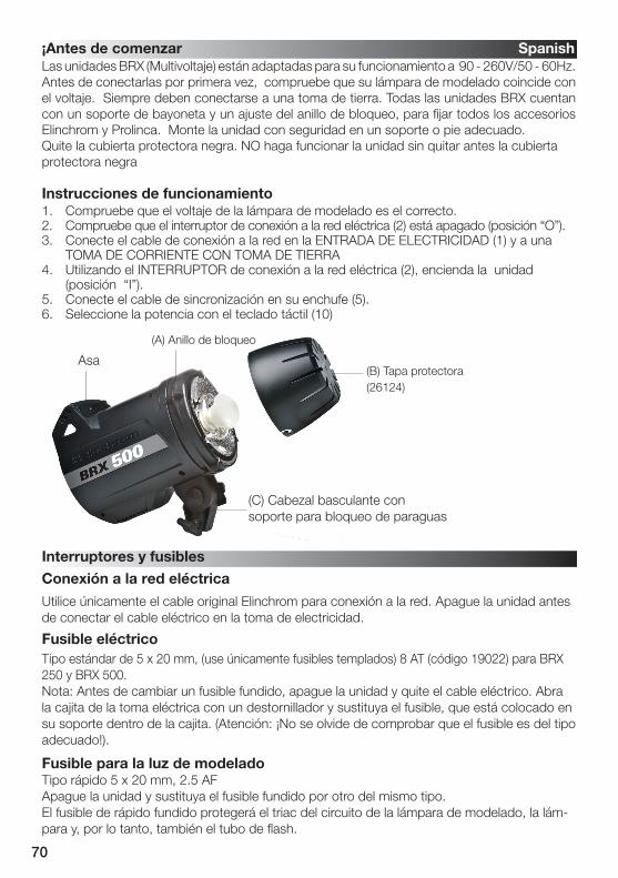
The BRX (Multivoltage) units are adapted for operation on 90 - 260V/50 - 60Hz. Before connecting for the first time, check to make sure that your Modelling Lamp coincides with the voltage. They must always be connected to an earthed ( grounded) mains supply. All BRX units have a bayonet mount and locking ring fitting, for fixing all Elinchrom and Prolinca accessories. Mount the unit securely to a suitable stand or support.Remove the black protective cover. DO NOT operate the unit without first removing the black protective cover.
1.Check that the modelling lamp voltage is correct. 2.Check that the mains switch (2) is in the OFF ("O" position).3.Insert the mains cable into the MAINS INLET (1) and connect this to a FULLY EARTHED OUTLET4.Using the mains SWITCH (2), switch the unit ON ("I" position).5.Connect the synchro cord using the socket (5).6.Select the power with the touch pad (10)
Operating instructions
(A) Locking ring
Handle
(C) Tilthead with locking umbrella holder
(B) Protective cover(26124)
Before you start ! English
Switch and fuse
Mains supply
Mains fuse
Fuse for modelling light
Use only the Elinchrom mains cord. Switch off the unit before the mains cord is connected to the mains plug.
Standard type 5 x 20 mm, use only tempered fuse 8 AT (code 19022) for BRX.Note: Before exchanging a blown fuse, switch off the unit and remove the mains cable. Open the little drawer in the mains plug with a screwdriver and replace the fuse with the spare fuse, which is placed in its support in this drawer. (N.B. Please don’t forget to check the correct rating of the fuse!).
Fast type 5 x 20mm, 2.5 AF Switch off the unit and replace the blown fuse with a new one of the correct rating.The fastblow fuse will protect the triac of the modelling lamp circuit, the lamp and therefore the flash tube.
8
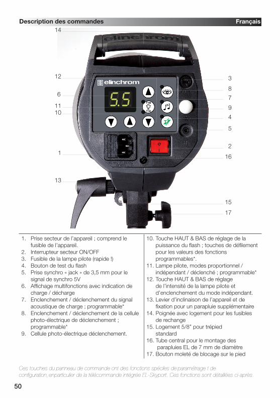
Overview of controls
1. Mains inlet socket includes the mains fuse (slow blow)2. Mains on/off switch3. Modelling lamp fuse4. Open flash / Test button5. Synch socket / 3.5 mm jack / low 5V sync voltage6. Digital multi display and charge / discharge indicator* 7. Charge Ready Beep on/off – programmable*8. Eye-Cell on/off – programmable* 9. Eye-Cell receptor10. Power up & down buttons and scroll /pro gram buttons for advanced features setup*
11. Modelling lamp on/off-free-prop – programmable*12. Modelling lamp up & down buttons and scroll /program buttons for advanced features setup*13. Tilt head with extra umbrella fitting14. Handle with support for spare fuses 15. Standard stand socket 5/8 inch16. Centred umbrella tube for EL Umbrellas – 7 mm diameter17. Knurled clamp screw
Control panel English
*The touches on this display are multifunctional to program / scroll the advanced features and to setup the integrated EL-Skyport Transceiver. For programming please read carefully the following pages!
1
13
9
2
16
15
17
4
7
8
5
3
6
11
12
14
10
9
Modelling lamps and fuses for 110 V & 230 VUnit Modelling lamp 110V Modelling lamp 230V Socket Fuse
How to „Reset“ the BRXIn case you need to „RESET“ the BRX to the manufacturer settings please follow the steps below:1. Switch the unit “off“2. Press both flash power up / down buttons (10) at the same time and switch the unit on3. The Digital LED multi display (6) flashes in fast mode4. Do not continue to press the touches, the resetting procedure is completed
Modelling lamp modes> Setting: • Press “Free/Prop” button to set Modelling lamp ON to proportional mode or OFF • Press “Modelling” up or down button to set Modelling lamp to free mode, press “Free/Prop” to switch Modelling lamp OFF.> LED Indication: • Prop-LED is ON: proportional Modelling lamp setting. • Free-LED is ON: free Modelling lamp setting. • Prop and Free-LED’s are OFF: Modelling lamp is inactive.
Setup Visual-Flash-Control (VFC) mode
Proportional modelling lamp setup (PMS)
> Enter VFC setup :1. Press “Free/Prop” push button for more than 2 seconds, until the display shows “F.X” (“X” is 0 or 1) to enter into the Modelling lamp setup menu. 2. Use the “Flash-Power” up and down button to change setting: - “F.0”: Visual-Flash-Control = OFF. Modelling lamp remains ON after flash.- “F.1”: Visual-Flash-Control = ON. Modelling lamp switches off during recharging.3. The display switches back to normal mode after approx. 4 seconds if no button is pressed. The settings are automatically stored.4. Standard setting is “F.0”, VFC = OFF
> Enter PMS setup:1. Press “Free/Prop” button for more than 2 seconds to enter into the Modelling lamp setup menu. The display shows “F.X”, then press the “Free/Prop” button once more to the PMS menu, the display shows “-.X” 2. Use the “Flash-Power” up and down button to change the settings:• “-.0”: PMS = OFF, Modelling lamp is set to maximum.• “-.1”: PMS = -1 f-Stop, Modelling lamp is reduced by 1 f-stop.
(When using heads of different maximum power)
10
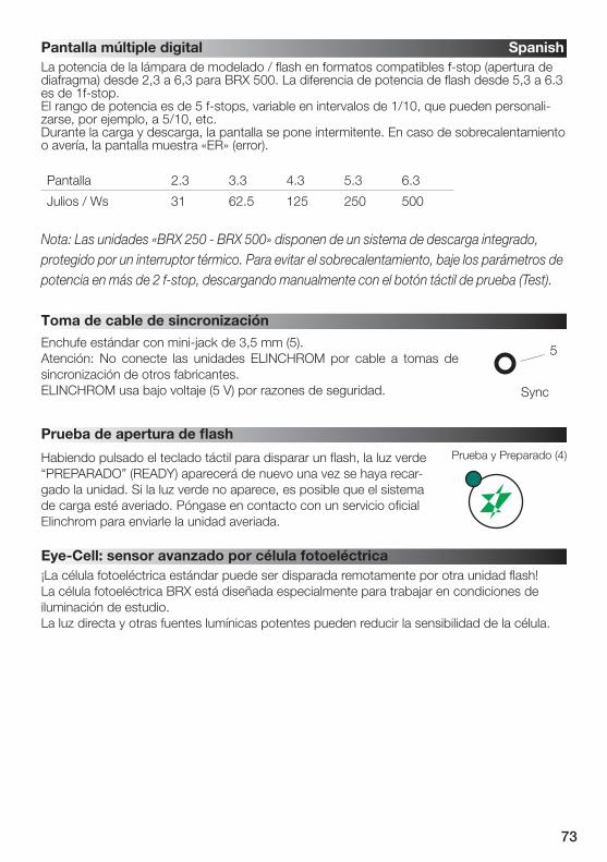
The flash / modelling lamp power is displayed in f-stop compatible formats from 2.3 – 6.3 for BRX 500. The flash power difference from (e.g.) 5.3 – 6.3 is 1f-stop. The power range is 5 f-stops variable in 1/10th intervals which can be customised to (e.g.) 5/10th etc.. During charging or discharging, the display «flashes». In case of overheating or malfunction, the display shows «ER» for error.
Display 2.3 3.3 4.3 5.3 6.3
Joules / Ws 31 62.5 125 250 500
Note: The «BRX 250 - BRX 500» units have an integrated discharge system, protected by a thermalswitch. To avoid overheating, lower power settings of more than 2 f-stops by discharging manually with the «Test» touch button.
Digital multi-display English
Sychronisation socket
Open flash «test»
The standard photocell can be remotely triggered by another flash unit!The BRX photocell is specially designed to work in studio light conditionsDirect light or other strong light sources may reduce the sensitivity of the cell.
Eye-Cell – advanced photocell sensor
Having pressed the touch pad to release a flash, the green «READY» light will appear again once the unit is recharged. If the green light does not appear the charge system could be defective. Please contact and send to an authorized Elinchrom service centre.
Test and Ready (4)
5
Sync
Standard socket with 3.5 mm mini-jack (5).N.B. Do not link ELINCHROM units by cable to other manufacturers sync. outlets. ELINCHROM uses the low voltage (5 V) for security reasons.
11
Intelligent Photocell-Sensor
Push “Cell” button, for less than 0.5 seconds to switch on/off the standard Photocell sensor. LED Indication: Cell LED is ON: Active photocell. Cell LED is OFF: Inactive photocell.In “on” mode, the Photocell sensor will trigger the flash unit with any recognized flash impulse.
The Eye-Cell offers new features and can detect camera pre-flashes (anti red eye effect).To customise the pre-flash settings, please follow the instructions at paragraph 3.
(This is only activation, not the setup. To Setup, follow step 3)Press the Cell button for approx. 1 second; the status LED starts flashing.LED Indication:Cell LED flashes in slow intervals; the Eye-Cell pre-flash mode is activated.Cell LED is OFF; the Eye-Cell pre-flash mode is inactive.Function:In active mode the unit ignores up to 6 anti-red-eye flashes and synchronizes / triggers only with the last main flash. This is useful where the anti-red eye pre-flashes can’t be switched off.
Eye-CELL Setup English
Press the Cell button for 4 seconds until display shows “c.X” for automatic setup. (“X” is the number of pre-flashes including main flash from 1 up to 7)Scroll with the “Flash-Power” up and down button to “c.0”Now use the camera-on flash and release a test exposure. The camera will release several anti-red eye flashes (if activated). The BRX Eye-Cell detects the number of flashes the camera released and stores the value automatically, and switches back to Eye-Cell Pre-flash mode. Ready to use.
If the cell button was pressed down for 6 seconds the “Setup Pre-Flash Timeframe” is activated and the display shows t.4 or b.1 (standard settings). Do not change these values; this would deactivate the “Automatic Eye-Cell Mode”! Wait a few seconds, the unit switches back to the standard mode and the display shows the flash power settings. Should the t.4 or b.1 values have been changed, please set the “Setup Pre-Flash Timeframe” back to standard settings as descript at paragraph 4.
Eye-Cell Functions1. Standard Photocell mode 2. Eye-Cell pre-flash mode3. Setup number of pre-flashes manually or set to automatic detection4. Setup pre-flash timings! Only for advanced users!
3. Automatic Eye-Cell Pre-Flash Setup “c.0”
1. Using the Standard Photocell Mode
2. Eye-Cell Pre-Flash Mode
!
12
Value t 1 2 3 4 5 6 7 8
Time /seconds 1 2 3 4 5 6 7 8
Change manufacturer settings only in case of problems with the auto-detection of your camera pre-flashes.> Setting:• Press Cell button for more than 6 seconds until display shows “t.X” (“X” is the value from 1 to 8)• Use the Cell button to toggle between “t.X” and “b.X” settings.• Use the “Flash-Power” up and down buttons to change the values.• The display switches back to normal mode after approx. 4 seconds if no button is pressed.
The settings are automatically stored. • Standard settings are:---> t.4 (t. is the time window of all released anti red-eye flashes incl. the main flash).---> b.1 (b. is the minimum time delay between two anti red-eye flashes incl. the main flash).
t. is the time window of all released anti red-eye flashes incl. the mainflash. Change setting only when the pre-flash procedure is longer than the manufacturer settings.Set the value t. between 1 and 8 to ensure that all pre-flashes including the main flash are inside the time frame.
Pre-Flash Block Time Setting “b.X”: (Only For LED Anti Red-Eye Cameras)Pre-Flash Block -Time: set the minimum delay between each pre-flash.Chose values between 0 and 7.
A. Press Cell button approx. 4 seconds until display shows “c.X”. (“X” is the number of settable pre-flashes plus the main flash from 1 up to 7)
B. With “Flash-Power” up and down button, set the number of pre-flashes incl. mainflash.C. The display switches back to normal mode after approx. 4 seconds if no button is pressed.
The settings are automatically stored. D. Cell LED flashes in fast intervals if the Eye-Cell pre-flash mode is active.
> Recall The Eye-Cell Settings:If you want to recall and control the actual Eye-Cell pre-flash setting, repeat the steps A to D.
Value b 0 1 2 3 4 5 6 7
Time: m/seconds 0 2 4 6 8 10 12 14
5. Setup Pre-Flash Timeframe (only for advanced users)
4. Manual Eye-Cell Pre-Flash Setup
Pre-Flash Timeframe Setting “t.X
!
13
Value A 1 2 3 4 5 6 7
Beep-On-Time in m/seconds 70 140 210 280 350 420 490
Charge Ready Beep Setup• Setting - Press “Audio” button, less than 0.5 seconds to switch the Charge Ready Beep (ON / OFF)• LED Indication - Charge Ready Beep LED is on: Audio is active - Charge Ready Beep LED is off: Audio is inactive (Mute)• Changing Charge Ready Beep -On-Time Setting - Press Audio button for more than 2 seconds until the display shows “A.X” (“X” is the value from 1 up to 7) - Use the Flash-Power” up and down button to change the value settings - The display switches back to normal mode after approx. 4 seconds if no button was pressed. The settings are automatically stored. - Standard setting is: “A.3”
This feature creates a melody if settings are different between each unit to improve the acous-tical recognition that all the flashes have fired and recycled.
Charge Ready Beep Features English
14
EL- Skyport Transceiver For Wireless Triggering – Setup English
Group Settings
Frequency Channel Settings
Power Steps Per Push
EL-Skyport on / off
The EL-Skyport on / off, Group, Frequency Channel and the Power Steps Per Push can becustomised.
Press the flash power up-down buttons together to enter into the “Advanced Feature Setup” Display shows Change settings with the flash power up-down buttonsr.0 EL-Skyport offr.1 EL- Skyport onr.2 EL-Skyport speed mode (only available with EL-Skyport Speed)After 3 to 4 seconds the settings are saved automatically and the display shows the flash power setting.
Press the flash power up-down buttons together to enter into the “Advanced Feature Setup”.Then, scroll to G.1 using the Prop/Free button.Display shows Select Group with the flash power up-down buttonsG.1 Group 1 (standard setting)G.2 Group 2G.3 Group 3G.4 Group 4After 3 to 4 seconds the settings are saved automatically and the display shows the flash power setting.
Press the flash power up-down buttons together to enter into the “Advanced Feature Setup”.Then, scroll to F.1 using the Prop/Free button (only use in cases of interference with other systems).Display shows Change the Channel with the flash power up-down buttonsF.1 to F.8 Select Frequency Channel from 1 – 8. Note: The transmitter must have the same Frequency Channel setting. Standard setting is Frequency Channel 1.After 3 to 4 seconds the settings are saved automatically and the display shows the flash power setting.
Press the flash power up-down buttons together to enter into the “Advanced Feature Setup”Then, scroll to i.1 using the Prop/Free button.Display shows Select values with the flash power up-down buttonsi.0 +/- 1f-stopi.1 +/- 1/10 (standard setting)i.2 +/- 2/10i.3 +/- 3/10i.4 +/- 4/10i.5 +/- 5/10
After 3 to 4 seconds the settings are saved automatically and the display shows the flash power setting.
15
To replace the flash tube:1. Switch off the mains switch2. Remove the mains cable3. Take the unit from its stand or lay it horizontally on a rigid surface. It will need to be held firmly whilst removing and replacing the tube.4. Allow the flash tube and modelling lamp to cool for several minutes. They may be very hot.5. Carefully remove and store the modelling lamp. 6. Use a protective glove to remove the flashtube:
A – Pull the flash tube firmly out of the terminalsB – If the tube is broken, use security gloves. Avoid cutting yourself!C - If the tube is broken, never touch the metal electrodes and ensure that the unit is disconnected from the mains and discharged, wait min. 30 minutes! Use an insulated tool to pull out the electrodes.
7. Take the new flash tube. A glove or "plastic protection" MUST BE USED. Contact with your fingers on the glas, will cause dark markings on the tube when it is used.8. Check that the tube is correctly aligned (central) and that the trigger contact is gripping the tube.9. Re-connect and test the unit as usual.
Flashtube replacement English
Error Management
E1Overvoltage detected
Switch unit OFF, wait 2 minutes and switch unit ON again. If the error shows up again the unit requires a check up at the Elinchrom service centre
E2 OverheatingWait until the unit has cooled down. The unit will switch back to normal opera-tion as soon as temperature decreases to normal working level.
E3Auto dump function fault
The Unit has detected a time out in the ADF mode. Switch the unit OFF, wait 2 minutes and switch the unit ON again; use the Test release button for power reduction. If the error shows up again the unit requires a check up at the Elin-chrom service centre.
E4 Charge faultUnit has detected a time out during recharging. Switch unit OFF, wait 2 minutes and switch unit ON again. If the error shows up again the unit requires a check up at the Elinchrom service centre.
E5Mains supply fault
Unit has detected a mains supply fault. Check your mains cord and mains installation sockets. Switch unit OFF, wait 2 minutes and switch unit ON again. If the error shows up again the unit requires a check up at the Elinchrom service centre.
E8Fan manage-ment fault
Unit has detected a FAN management problem due to overheating. Wait until the unit has cooled down. Check if the FAN is blocked. If the error shows up again the unit requires a check up at the Elinchrom service centre.
Error Fault Description
If the unit does not flash but the ON/OFF switch indicates that there is power, it could be that the flash tube needs replacing. Flash tubes have a long life with average use, but multiflashing in long sequences can cause overheating of the electrodes leading to premature ageing, or perhaps the flastube is broken or cracked
16
Flash power J(Ws) 250 500
Power supply V 90/260 90/260
F-stop, 1m, 100 ISO, with reflector 48° 64 90
Power range J(Ws) 16-250 31-500
Variable flash power f-stops 5 f-stops 1/16 - 1/1
Recycling time, min. / max. (230 V) s 0.29 / 0.73 0.36 / 1.13
Recycling time, min. / max. (115 V) s 0.27 / 1.02 0.34 / 1.45
Colour temperature max. power °K 5360 5410
Flash duration (t 0,5) 1/1 s 1/2762 1/1558
Flash duration (t 0,5) 1/2 s 1/2165 1/1395
Voltage stabilisation ± 0.5 % Maximum stability for digital imaging
Sync voltage V 5 V, maximum compatibility with digital cameras
Radio interference suppressiv CE-IEC 491 EN 60 555 - EN 61 000 - 4 - 2/3/4/5
Tolerances and specifications conforming to IEC and CE standards. Technical data subject to change without notice.
Technical data BRX 250 BRX 500
17
C o n t e n t s :
Features 18
Battery Installation 18
Hot-shoe connector 18
Operating Instructions 18
Frequency Channel 19
Trigger Modes 19
Integrated SYNC Socket 20
Elinchrom RX Features 20
EL-Skyport Modules 21
Troubleshooting 21
CE Statements 22
FCC Compliance and Advisory Statement 22
Disposal and recycling 22
User Manual
Transmitter Speed1 9 3 5 0
English
18
• SLR Camera Sync speeds: SPEED mode up to 1/250 s, STANDARD mode 1/160 - 1/200 s.
• 5 selectable trigger modes, (4 Groups + All)• 8 frequency channels.• 40 Bit security encryption.• Up to 60 m range indoors for standard mode and
up to 40 m in speed mode.• Up to 120 m range outdoors for standard mode
and up to 60 m in speed mode.• Battery life up to 6 Months - over 30’000 flashes.• RX-feature buttons (Remote Control).• Test trigger button and feature button.• Integrated Hot-shoe (middle contact) improved.• SYNC-socket for direct connection improved.• Two flash modes, standard and speed.• The “Standard” mode is fully compatible with
previous EL-Skyport versions.• The SPEED function is available for Ranger Quadra AS, BXRi 250 / 500 und D-Lite it and all other units, when used with the Universal Speed.
Hot-shoe with screw lock and SYNC socket
Battery drawer
Battery (19372) Minus pole on top Flexible swivel
Antenna 360 ̊Fig. 1
Battery Installation1. Pull the battery drawer out carefully.2. Place the Lithium battery, see Fig. 1 for correct polarity.3. Close the battery drawer.
! CAUTION:• Ensure correct polarity / minus pole on top.• Use only the Lithium Battery CR2430 3.0 V 19372.• Remove battery if the EL-Skyport Transmitter is not used for some time.• Never short-circuit battery poles.• Avoid direct sunlight or temperatures above 45°C. The battery may explode!
Hot-Shoe Connector with Screw-LockThe new Hot-shoe connector with screw-lock and middle contact synchronisation is designed to fit digi-tal and analogue cameras with maximum sync output of 3 V (the middle contact is the positive pole).
Operating Instructions
• Status LED for EL-Skyport mode and battery status.• Improved housing, battery drawer and
switches.• New Hot-shoe with screw-lock.• New extra features; configure EL-Skyport with
the new EL-Skyport PC / MAC software 3.0.
You will appreciate the convenience of this professional and powerful wireless device.
Note: Shutter speed and distance range are influenced by interference from other 2.4 GHz electronic equipment and reflections of ceilings, walls, floors, furniture, metall, trees and humidiy in woods etc. For better performance the Transmitter and Receiver antenna should have direct sight, without any walls or objects in - between.
Frequency ChannelNote:Transmitter and the corresponding Transceiver RX, the Universal Receiver or the EL units with integrated EL-Skyport Receiver must have the same frequency channel settings!
FrequencyChannel
Slide Button configuration Frequency/ Mhz1 2 3
1 (default) Off Off Off 24562 On Off Off 24583 Off On Off 24604 On On Off 24625 Off Off On 24696 On Off On 24717 Off On On 24738 On On On 2475
EL-Skyport Sync Speed & Standard ModeThe SPEED function is available for Ranger Quadra AS, BXRi 250 / 500 und D-Lite it and all other units, when used with the EL-Skyport Universal Speed.
Select “Speed” sync modeSynchronises SLR cameras up to 1/250 s, or compact digital cameras up to 1/2850 s- Select “Group” or “All” mode.- Press test push button for minimum 5 seconds until the STATUS LED flashes two times.- Release test push button.- Now the EL-Skyport Transmitter Speed works in “SPEED” mode (r.2 mode).
Select “Standard” triggering modeSynchronises SLR cameras up to 1/200 s, or compact digital cameras up to 1/1600 s- Select “Group” or “All” mode.- Press test push button for minimum 5 seconds until the STATUS LED flashes one time.- Release test push button.- Now the EL-Skyport Transmitter Speed works in “STANDARD” mode.
EL-Skyport Module Configuration:Only possible with EL-Skyport PC / MAC software v 3.0 and higher.- Power-Save Timer, individual programmable or disabled.- Trigger delay is programmable from 250 ms up to 15 s.- Download the FREE EL-Skyport Software from www.elinchrom.com
English
20
SET Config Mode: (to configure included features)- Switch module OFF.- Hold test push button and switch TX ON.- Keep test push button pressed until STATUS LED is ON. Check also EL-Skyport PC / MAC software 3.0 for changing Transmitter Speed setting.
The EL-Skyport Transmitter triggers the EL-Skyport Receiver modules in the following modes:1. Off Unit is OFF, no function.2. Select Group - Group (1 to 4). Set switch to Group. and select Group 1 to 4. All corresponding EL-Skyport Receivers with the same selected Group (1 to 4) are triggered.3. ALL Mode switch is set to ALL. All corresponding EL-Skyport Receivers are triggered regardless of which Group is selected.
Integrated Hot-Shoe SYNC 2.5 mm SocketUse the included Sync cable to connect the integrated 2.5 mm Mono Jack socket with the camera or lens PC socket directly.
EL-Skyport Transmitter SPEED RX FeaturesCompatible with Ranger RX, Style RX, Digital RX, BXRi 250 / 500, Ranger Quadra AS!If the EL-Skyport Transmitter SPEED is used with the EL-Skyport Transceiver RX, BXRi 250 / 500 or the Ranger Quadra AS, the following EXTRA features are available:Depending upon which Group is selected, the following RX-unit settings can be modified:1. Flash power increase in 1/10 f-stops. press push button + to increase the power of selected Group of (or ALL) RX-units in 1/10 f-stops.
2. Flash power decrease in 1/10 f-stops. press push button - to reduce the power of selected Group of (or ALL) RX-units in 1/10 f-stops.
3. Modelling lamp toggle. press and hold the push button +, 2 seconds or longer before releasing, to toggle modelling lamp of the selected Group of (or ALL) RX-units.
Power save mode timer:- After not using the Transmitter for 30 minutes the Power Save mode is active. To reactivate the Transmitter, press the TEST push button.- The Power Save mode timer can be configured with the EL-Skyport PC / MAC software v 3.0 and higher.
Status LED:- LED flashes every 4 seconds one time in “Standard” mode and two times in “Speed” mode.- LED intensity correspond to the battery status - if off or very low => exchange the battery.- LED is OFF if the Transmitter is switched OFF or in Power Save mode..Reset to manufacturer default setting:- Switch ON.- Press test button for min 10 seconds.
English
21
EL-Skyport Modules
EL-Skyport Universal SPEED (NEW) / Universal (previous version) • Universal Receiver for all makes of Flash with a SYNC socket, conforming to Sync norms!
EL-Skyport Transceiver RX • This Transceiver is only for Elinchrom RX units. The module operates all RX features with the EL-Skyport software and triggers the flash.
EL-Skyport USB RX SPEED (NEW) / USB RX (previous version) • To operate RX flash units via computer the USB module should be used in conjunction with the EL-Skyport Transceiver RX and the EL-Skyport software.
TroubleshootingShould an error occur, first check the following points:
Having this problem? Check the following points:
No flash unit can be triggered with the TransmitterMode “All” is selected
Check if the Transmitter is switched ON. Check battery polarity. Check if the Receiver module is connected correctly to the unit. Check if the frequency selector switch is set to the same channel. Check if Transmitter is in the same trigger mode Speed or Standard.
Some units do not fire when triggered with the TransmitterMode “Grp” is selected
Check if the Channel selector switch is set to the same Group. Reduce distance to any “not working” unit. Check if Transmitter is in the same trigger mode Speed / Standard.
TEST flash works, but the camera will not trigger flash unit
Check hot-shoe fitting. Connect the 2.5 mm to PC SYNC cable instead of hot-shoe connection.
Limited Distance range Reposition the units. Increase the distance to walls and ceilings. Position the antenna of Transmitter and Receiver. Use an RX extension cable to reduce the distance between the modules.
English
Universal Speed& Universal
Transceiver RX19353
USB RX Speed& USB RX
22
CE Statements
This device has been tested and found to comply with the requirements setup in the council directive on the approximation of the law of member states relating to EMC Directive 89/336/EEC, Low Voltage Directive 73/23/EEC and R&TTE Directive 99/5/EC
FCC Compliance and Advisory StatementThis device complies with Part 15 of the FCC rules. Operation is subject of the following two condi-tions: 1. this device may not cause harmful interference, and 2. this device must accept any interfer-ence received, including interferences that may cause undesired operation.
The equipment has been certified to comply with the limits for a Class B computing device pursuant to Part 15 of the FCC Rules. These limits are designed to provide reasonable protection against harm-ful interference in a residential installation. This equipment generates, uses, and can radiate radio frequency energy and, if not installed or used in accordance with the instructions, may cause harmful interference to radio communications. However, there is no guarantee that interference will not occur in a particular installation. If this equipment does cause harmful interference to radio or television re-ception, which can be determined by switching the equipment off and on. The user can try to correct the interference by the following measures:1. Reorient or relocate the receiving antenna2. Increase the separation between the equipment and receiver3. Connect the equipment to an outlet on a circuit different from that to which the receiver is con-nected.4. Consult the dealer or an experienced radio/TV technician for help, changes or modification not expressly approved by the party responsible for compliance could avoid the user’s authority to operate the equipment.
Disposal and recycling This device has been manufactured to the highest possible degree from materials which
can be recycled or disposed of in a manner that is not environmentally damaging. The device may be taken back after use to be recycled, provided that it is returned in a condi-tion that is the result of normal use. Any components not reclaimed will be disposed of in an environmentally acceptable manner.
If you have any question on disposal, please contact your local office or your local ELINCHROM agent (check our website for a list of all ELINCRHOM agents worldwide).
English
23
VERMERK: Toleranzen der technischen Daten für Bauelemente und Messwerte entsprechenden IEC und EC Normen. Technische Änderungen vorbehalten. Die Werte können durchBauelementetoleranzen schwanken und sind als Richtwerte zu verstehen und nicht im rechtlichen Sinne als zugesicherte Eigenschaften. Keine Haftung für Druckfehler.
BRX Kompaktblitzanlagen wurden von Elinchrom S.A. LTD. / Schweiz entwickelt.ELINCHROM verwendet für seine Produkte nur hochwertige und geprüfte Baukomponenten.Die Endkontrolle sichert die Einhaltung des Qualitätsstandards und garantiert eine einwandfreieFunktion. Wir hoffen, dass Sie mit diesem Gerät vollkommen zufrieden sind. Um einwandfreie Ergebnisse zu bekommen und die zuverlässige Funktion für lange Zeit zu sichern, sind nachstehendeGebrauchsanweisungen und Vorsichtsmassnahmen zu befolgen.
BRX 250 / BRX 500 Compact Flash
Die hervorragende Lichtqualität und die technische Leistung der BRX Kompaktblitzanlagenberuhen auf einer 45 jährigen Erfahrung auf dem Gebiet der Blitzelektronik und derHerstellung von Blitzanlagen. Elinchrom Blitzlichtprodukte entsprechen den gültigen elektrischenNormen.
This equipement has been tested and found to comply with the limits for a class B digital device, pursuant to Part 15 of the FCC Rules and meets all requirements of the Canadian Interference-Causing Equipement Regulations. These limits are designed to provide reasonable protection against harmful interference in a residential installation. This equipement generates, uses, and can radiate radio frequency energy and, if not installed and used in accordance with the instruction manual, may cause harmful interference to radio communications. However, there is no guarantee that interference will not occur in a particular installation. If this equipement does not cause harmful interferences to radio or television reception, which can be determined by turning the equipement off and on, the user is encouraged to correct the interferences by one or more of the following measures: • Reorient or relocate the receiving antenna.• Increase the separation between the equipement and receiver.• Connect the equipement into an outlet on a circuit different from that to which the receiver is connected.• Consult the dealer or an experienced radio/TV technician for help.ELINCHROM S.A. LTD. is not responsible for any radio or television interference caused by unauthorised modifications of this equipement or the substitution or attachment of connecting cables and equipement other than those specified by ELINCHROM S.A. LTD. The correction of interference caused by such unauthorised modification, substitution or attachment will be the responsibility of the user.
FCC Class B Compliance Statement / USA
Einführung Deutsch
25
ZeichenerklärungIn diesem Handbuch werden folgende Darstellungsmittel verwendet.
Kennzeichnet Hinweise, bei deren Nichtbeachtung Ihre Gesundheit, die Funk-tions fähigkeit Ihres Gerätes oder die Sicherheit Ihrer Daten gefährdet sind. Kennzeichnet zusätzliche Informationen bzw. Tipps. “Anführungszeichen” kennzeichnen Kapitelnamen und Begriffe, die hervorgehoben werden sollen. Kursive Schrift kennzeichnet Bedienelemente, Baugruppen oder Menüpunkte.
Dieses Gerät entspricht Paragraph 15 der FCC Normen, die folgende Punkte beinhalten:1. Dieses Gerät verursacht keine Interferenzen die nicht den Normen entsprechen.2. Dieses Gerät akzeptiert jegliche Interferenzen, auch die, die eventuell Störungen verursachen können.
Produktbeschreibung; BRX 250 / BRX 500
Marktname: ELINCHROM
Modelle: 20440.1 / 20441.1
Verantwortliche Firma: Elinchrom LTDAv. De Longemalle 111020 Renens / Switzerland
Phone : +41 21 637 26 77
Fax: +41 21 637 26 81
ELINCHROM S.A. LTD., erklärt mit ihrem Marktnamen, dass die Geräte mit den genanntenModellnamen nach den einschlägigen EWG, DIN, IEC und FCC Normen geprüft und getestetwurden und allen Vorschriften entsprechen. Alle notwendigen Prüfungen wurden durchgeführt um die Einhaltung und Sicherheit auch während der Serienproduktion
Konformitätserklärung Deutsch
CE Kennzeichnung für EL-SkyportDieses Gerät erfüllt in der ausgelieferten Ausführung die Anforderungen der EG Richtlinie 89/336/EWG „Elektromagnetische Verträglichkeit“ und 73/23/EWG “Niederspannungsrichtli-nie” und die Richtlinie nach R&TTE 99/5/EC.
Entsorgung and Recycling Dieses Gerät wurde weitestgehend aus Materialien hergestellt, die umweltschonend
entsorgt und einem fachgerechten Recycling zugeführt werden können. Nach seinem Gebrauch wird das Gerät zurückgenommen, um es einer Wiederverwendung bzw. werkstofflichen Verwertung zuzuführen, soweit es in einem Zustand zurückgegeben
wird, der dem bestimmungsgemäßen Gebrauch entspricht. Nicht verwertbare Geräteteile werden sachgemäß entsorgt. Bei Fragen zur Entsorgung wenden Sie sich bitte and Ihre Verkaufsstelle. Eine Liste aller Verkaufsstellen in Ihrer Nähe finden Sie auf unserer Homepage www.elinchrom.com.
CE Zertifizierung Dieses Studioblitzgerät entspricht den Anforderungen der EWG Richtlinie 89/336/ EWG Elektromagnetische Verträglichkeit” und 73/23/EWG “ Niederspannungsrichtlinie”.
!
26
!
• Transportieren Sie Ihre Blitzgeräte vorsichtig und nur in der Originalverpackung oder einer anderen geeigneten Verpackung, die Schutz gegen Stoß und Schlag gewährt.• Vermeiden Sie Kondensationsprobleme durch starke Temperaturschwankungen.• Der Transport darf nur im völlig entladenen Zustand erfolgen. Warten Sie vor dem Transport des Gerätes mindestens 30 Minuten nach der Trennung der Versorgungsspannung.• Lassen Sie niemals Ihr Gerät fallen (Das Blitzröhrenglas kann brechen).
NetzleitungUm die Betriebssicherheit des Gerätes zu gewährleisten, benutzen Sie nur originale Netzkabel.• Die Netzleitung muss HAR- oder VDE- Zertifizierung aufweisen. Die Markierung HAR oder VDE ist am Gerätestecker bzw. – Buchse aufgedruckt.• Die Strombelastbarkeit muss dem Gerät entsprechen.• Verwenden Sie keine Mehrfachsteckdosen um mehr als ein Gerät zu betreiben.
• Blitzgeräte speichern elektrische Energie in Kondensatoren mit hoher Spannung.• Kondensatoren können explodieren während das Gerät benutzt wird.• Niemals defekte Blitzgeräte einschalten.• Das öffnen, modifizieren und reparieren der Blitzanlagen ist verboten.• Nur von Elinchrom autorisierte Werkstätten dürfen Reparaturen vornehmen.• Schalten Sie wegen der hohen elektrischen Spannung an den Kontaktendas Blitzgerät nicht ein, ohne dass Kameraleuchte oder Blitzröhre angebrachtsind! Lebensgefahr!
Dieses elektronische Blitzgerät sollte nicht im Freien, bei unzureichender Stromzuführung, auch nichtin einem feuchten oder staubigen Umfeld eingesetzt werden; achten Sie ebenfalls darauf, dassdie Luft nicht mit Fremdgasen angereichert ist. Die elektrische Steckdose muss den Normenentsprechen und geerdet sein.• Blitzanlagen nur mit Genehmigung der Zuständigen, in Krankenhäusern, Museen, Fabriken, Wissenschaftlichen Instituten , etc. verwenden.• Dieses Gerät nicht in verbotenen oder explosiven Bereichen verwenden.• Lassen Sie niemals Kinder unbeaufsichtigt mit Blitzanlagen allein!!• Nur originales Elinchrom Zubehör verwenden.
• Blitzröhren und Pilotlicht werden bei Gebrauch sehr heiß.• Sie dürfen nicht in der Nähe von brenn- und entflammbarem Material benutzt oder unmittelbar nach der Benutzung dort aufbewahrt werden.• Schauen Sie niemals direkt in das Blitzlicht!• Das Blitzgerät muss vom Stromnetz getrennt werden, abkühlen, bevor eine Sicherung / Halogenlampe / Blitzröhre gewechselt wird.• Die Wartezeit beträgt mindestens 30 Minuten.• Niemals Blitze aus geringem Abstand auf Personen auslösen. Der Mindestabstand sollte 1 - 2 m betragen, abhängig von der eingestellten Blitzleistung.• Grundsätzlich Abstand zu anderen elektronischen Geräten halten die in Funktion sind.
Sicherheitsvorschriften Deutsch
Transport
Blitzröhren und Pilotlicht
27
Grundfunktionen Deutsch
Zusätzliche programmierbare Sonderfunktionen
Die Grundfunktionen sind einfach zu bedienen und sind ähnlich zu vorherigen Elinchrom Blitzgeräten.
Alle neuen Funktionen können individuell programmiert werden.Lesen Sie dazu aufmerksam wie die Funktionen konfiguriert werden!
Als zusätzliche oder alternative Abblitzkontrolle schaltet sich das Einstelllicht während der Wiederaufladung ab, wenn diese Funktion aktiviert wurde.
Wenn z.B. BRX Blitzgeräte mit 250 und 500 J / Ws eingesetzt werden kann das Einstell-licht beim BRX 250 um 1 Blende herabgesetzt werden um eine bessere visuelle Kontrolle zu ermöglichen.
Proportionale Einstelllichtanpassung
Einige Kameras mit integriertem Blitz lösen Vorblitze aus um rote Augen zu vermeiden. Nor-malerweise lösen BRX Studioblitzgeräte bereits beim ersten Blitzimpuls aus was in diesem Fall eine Fehlsynchronisierung verursacht. Die Eye-Cell Photozelle kann so programmiert werden das, dass Gerät erst nach dem letzten Hauptblitz synchronisiert (bis max. 6 Vorblitze)
Eye-Cell automatische & manuelle Einstellung zur Erkennung von Vorblitzen
Die Tonlänge des Bereitschaftssignals kann individuell angepasst werden zur besseren Identifizierung der auslösenden Blitzgeräte.
Akustisches Bereitschaftssignal / Anpassung der Tonlänge
Der integrierte El-Skyport Empfänger kann zur Blitzsynchronisierung mit Gruppen- & Kanal-wahl, Einstellung der Blitzleistung oder zum Abschalten des Einstelllichtes verwendet werden. Dazu wird der optionale El-Skyport Transmitter / Sender benötigt.
EL-Skyport Blitzauslösung & Fernbedienung
Normalerweise wird die Blitz- und Einstelllichtleistung schrittweise mit dem Leistungstaster in 1/10 Blendenstufen eingestellt. Diese Stufen können von 1/10 – 7/10 oder auf eine Blende umprogrammiert werden.
Blitz- und Einstelllicht / Individuelle Anpassung der Leistungseinstellung
Der interne Mikroprozessor kontrolliert die Gerätetemperatur. Wird es zu warm schaltet sich das Kühlgebläse automatisch ein, bis die korrekte Betriebstemperatur erreicht wurde. Ist das Kühlgebläse blockiert oder defekt erscheint die Fehlermeldung E8 auf dem Display.
Temperaturgesteuertes Kühlgebläse
• Blitzleistungseinstellung mit „auf & ab“ Pfeiltasten• Einstelllichtleistungseinstellung mit „auf & ab“ Pfeiltasten• Einstelllichtfunktionen: proportional / frei / aus• Photozelle ein / aus• Akustische Ladebereitschaft ein / aus• Testblitz• Synchronisierungsbuchse für 3.5 mm • Integrierter EL-Skyport Empfänger zur Blitzlichtauslösung und Fernbedienung
28
Das BRX Blitzgerät ist mit einer Multivoltage-Technologie ausgestattet und kann mit 90V -260V /50-60 Hz Stromnetzen verwendet werden. Lediglich der Einstelllampenwert muss dem jeweiligen Stromnetz entspre-chen. Das Stromnetz muss geerdet sein. Dieses Gerät ist mit einem speziellen verschließbaren Bajonettring ausgestattet - wie alle anderen Kompaktgeräte und Blitzköpfe des Systems. Das Reflektorenprogramm ist voll kompatibel. Setzen Sie das Kompaktgerät auf ein Lampenstativ. Entfernen Sie die Schutzkappe, indem Sie den Verriegelungsring (A) nach links drehen, die Schutzkappe ebenfalls nach links drehen (B) und nach vorn entnehmen. Reflektoren werden in umgekehrter Reihenfolge adaptiert.Achtung: Wechselbare Blitzröhren müssen korrekt und fest in der Steckhalterung sitzen bevor das Blitzgerät eingeschaltet wird. Die Blitzröhre nur mit Schutzhandschuhen berühren, bzw. wechseln! Die Halogenlampe darf beim Einsetzen nicht mit den Fingern berührt werden (Plastikschutzhülle dazu benutzen).
1. Überprüfen Sie, dass die Netzanschluss-Steckdose geerdet ist und die Stromspannungmit der des Blitzgerätes / Einstelllampe übereinstimmt.2. Der Netzschalter muss auf AUS stehen.3. Netzkabel am Gerät einstecken und dann erst mit dem Stromnetz verbinden.4. Das Gerät mit dem Kippschalter / Netzschalter einschalten.5. Synchronkabel an die Synchronbuchse anschließen.6. Blitzleistung mit den Leistungstasten wählen.
Inbetriebnahme
Bajonettverriegelungsring (A)
Haltegriff
Zentrierte Schirmhalterung (C)
Schutzkappe (B)
Vor dem Start Deutsch
Netzanschluss & Sicherungen
Netzanschluss
Netzsicherung
Einstelllichtsicherung
Nur das originale Elinchrom Netzkabel verwenden. Der Kompaktblitz wird mit Strom versorgt, wenn der Netzschalter eingeschaltet ist. Diesen Schalter immer erst ausschalten, bevor das Netzkabel gezogen wird.
Nur Sicherungen des Typs 5 x 20 mm 8 AT (träge) verwenden.Bevor eine defekte Sicherung gewechselt wird, das Gerät abschalten und das Netzkabel entfernen. Öffnen Sie die kleine Sicherungsschublade am Netzeingangschalter mit einem Schraubendreher und wechseln Sie die Sicherung mit der in der Schublade befindlichen Reservesicherung aus.
Nur Sicherungen des Typs 5 x 20 mm 2.5 AF (flink) verwenden.Bevor eine defekte Sicherung gewechselt wird, das Gerät abschalten und das Netzkabel entfernen. Die flinke Sicherung schützt die Einstelllichtelektronik und die Halogenlampe vor Explosionen und damit auch die Blitzröhre vor Beschädigungen.
29
Kontrollelemente
1. Netzeingang mit Sicherungsschublade2. Hauptschalter ein / aus 3. Einstelllichtsicherung (flinke Sicherung)4. Testblitz 5. Synchroneingang 5V (für 3,5 mm Klinkenstecker)6. Digitale Multianzeige für Blitzleistung & andere Funktionen* 7. Bereitschaftssignal, programmierbar*8. Photozelle / Eye-Cell, programmierbar*9. Empfangselement Fotozelle10. Leistungseinstellung Blitz / Einstelllicht & Programmiertasten*
11. Einstelllicht, individuell – proportional - aus, programmierbar*12. Einstelllicht, Leistungsverstellung & Programmiertasten*13. Feststellgriff für Neigefunktion und zusätzliche Schirmhalterung14. Haltegriff mit Ersatzsicherungshalter15. Standard 5/8“ Stativhülse16. Selbstklemmende, zentrierte Schirmhalterung Ø 7 mm17. Stativ-Feststellschraube
Bedienteil Deutsch
*Diese Taster sind multifunktional zum programmieren und aufrufen der Menüfunktionen und zum einstellen der EL-Skyport Funktionen. Lesen Sie aufmerksam auf den nächsten Seiten, wie die Zusatzfunktionen programmiert werden können.
Zusätzliche programmierbare Sonderfunktionen - Reset DeutschDas BRX auf Herstellerkonfiguration zurücksetztenFalls das Gerät auf die Herstellerwerte zurückgesetzt werden soll bitte folgende Schritte aus-führen:1. Gerät abschalten2. Die Blitzleistungseinstellungstaster (10) gleichzeitig drücken und das Gerät einschalten3. Die LED Anzeige blinkt im schnellen Modus4. Die Taster nicht mehr drücken, das BRX wurde zurückgesetzt
Einstelllicht Setup
Einstellung Visual-Flash-Control (VFC) Optische Abblitzkontrolle(Das Einstelllicht erlischt nach dem abblitzen und schaltet sich nach dem Ladevorgang ein)
Proportionale Einstelllichtanpassung (PMS)
1. Den “Free / Prop“ Taster min. 2 Sekunden drücken bis im Display F.X anzeigt wird.2. Mit dem “Blitzleistung Auf /Ab“ Taster die Funktion VFC ein- / ausschalten. 3. “F.0“ VFC ist deaktiviert. Das Einstelllicht schaltet sich nach dem blitzen nicht ab.4. “F.1“VFC ist aktiviert. Das Einstelllicht schaltet sich während der Wiederaufladung ab!Wird kein Taster gedrückt, zeigt das Display nach 4 Sekunden wieder die eingestellte Blitzleis-tung an. Die gewählte Einstellung wird automatisch gespeichert. Bei der Werkseinstellung ist die VFC Funktion deaktiviert.
Einstellung Free / Prop / Aus1. Mit dem „Free / Prop“ Taster die Funktionen Einstelllicht Ein / Proportional / Aus auswählen.2. Mit dem „Einstelllicht Auf /Ab“ Taster die Funktion „Free“ aktivieren und die Leistung einstellen. 3. Mit dem „Free / Prop“ Taster dass Einstelllicht ausschalten.4. Die aufleuchtende LED zeigt die jeweilige Funktion an.
1. Den “Free / Prop“ Taster min. 2 Sekunden drücken bis im Display F.X anzeigt wird.2. Sofort den “Free / Prop“ Taster nochmals kurz drücken, das Display zeigt “-.X“ an.3. “-.0“ PMS ist deaktiviert.4. “-.1“ Das Einstelllicht wird um eine Blende reduziert (Das entspricht dem Leistungsunter-schied zwischen 250 J und 500 J Blitzgeräten)
(Bei Verwendung von Blitzgeräten mit unterschiedlicher Blitzleistung, 250 J und 500 J)
31
Die Blitz- und Einstelllichtwerte werden in einem Blendenkompatiblen Format von 2.3 – 6.3 für das BRX 500 angezeigt. Der Unterschied zwischen z.B. 5.3 – 6.3 ist eine Blende Lichtle-istung. 5 Blendenwerte sind einstellbar, variabel in 1/10 Blendenschritten. Diese Schritte kön-nen individuell, z.B. in 5/10 Stufen oder anderen Werten angepasst werden.
Während das Blitzgerät lädt oder entlädt blinkt das Display. Bei Überhitzung oder Elektronikfe-hlern zeigt das Display >E.X< Fehler, wobei X für die Fehlernummer steht. Das Display dient auch zum programmieren der Gerätefunktionen.
Displayanzeige BRX 500 2.3 3.3 4.3 5.3 6.3
Joules / Ws 31 62.5 125 250 500
Bemerkung: BRX 250 und 500 Blitzgeräte werden bei Leistungsreduzierung automatisch entladen. Ständiges entladen über mehr als 2 Blendenwerte kann zu Überhitzungen führen. In diesem Fall kann die überschüssige Blitzenergie auch manuell über den Test Taster abgeblitzt werden. Als Schutz vor Überhitzungen verfügen BRX Blitzgeräte über Thermofühler die entweder das Kühlgebläse automatisch einschalten oder das Gerät abschalten bis es die Betriebstemperatur erreicht.
Digitales Multi Display Deutsch
Synchronisierungsbuchse
Test Taster
Die eingebaute Photozelle lässt das Gerät bei Blitzimpulsen automatisch synchron auslösen. Die BRX Photozelle ist für den Studioeinsatz optimiert worden. Direktes und starkes einfallen-des Halogenlicht reduziert die Empfindlichkeit der Photozelle. Kompakt Kameras mit integriertem Blitz und der Anti Red-Eye Funktion konnten bisher mit herkömmlichen Studioblatzanlagen nicht verwendet werden, da die Photozelle schon mit dem ersten Vorblitz synchronisieren würde. Die Eye-Cell kann automatisch oder manuell so programmiert werden das sie Vorblitze ignoriert und erst mit dem Hauptblitz synchronisiert.
Über den Test Taster kann ein Blitz manuell ausgelöst werden. Wenn das Gerät wieder Blitzbereit ist leuchtet die LED Anzeige grün auf. Falls die LED nicht leuchtet, kann der Ladekreis defekt sein. In diesem Fall muss das Gerät zu einem qualifizierten EL-Service gebracht werden.
Test & Blitzbereitschaft (4)
5
Sync
BRX ist mit einer 3.5 mm Buchse ausgestattet. Nur Elinchrom Synchronkabel verwenden. Niemals EL- Blitzgeräte mit anderen Blitzanlagen über Synchronka-bel vernetzen. Elinchrom verwendet eine niedrige 5V Synchronspannung um angeschlossene Kameras zu schützen.
32
Den “Cell“ Taster max. ½ Sekunde drücken um die Photozelle ein- /aus zuschalten.Die aktive Photozelle wird mit einer leuchtenden LED angezeigt.Die eingeschaltete Photozelle reagiert auf jeden erkennbaren Blitzimpulse und löst das Blitzgerät synchron aus.
(Nur Aktivierung, die Konfiguration wird ab Schritt 3 beschrieben) Den „Cell“ Taster ca. 2 Sekunden drücken, die Photozellen LED blinkt.LED Indikation:LED blinkt in langsamen Intervallen; der Eye-Cell Vorblitzmodus ist aktiviert.LED ist aus; der Eye-Cell Vorblitzmodus ist ausgeschaltet.
Im Vorblitzmodus ignoriert die Eye-Cell bis zu 6 Vorblitze (Anzahl je nach Kameratyp) und synchronisiert erst mit dem letzten Hauptblitz. Kameras die mit der Anti Red-Eye Funktion ausgestattet sind können mit BRX Blitzanlagen korrekt synchronisiert werden.
Eye-Cell Funktionen Deutsch
Den “Cell“ Taster ca. 4 Sekunden drücken bis das Display “c.X“ (Automatische Vorblitzerken-nung) anzeigt. (“X“ entspricht der Anzahl der Vorblitze inklusive des Hauptblitzes von 1 – 7.)Mit den Blitzleistungstasten “auf – ab“ das Display auf “c.0“ einstellen.Stellen Sie die Kamera mit dem integriertem Blitz auf Red-Eye Funktion und lösen die Kamera in Richtung der Photozelle des BRX Blitzes aus. Die BRX Eye-Cell erkennt nun die Anzahl der Vorblitze inklusive des Hauptblitzes und speichert diesen Wert automatisch. Das BRX ist für die korrekte Synchronisierung einsatzbereit.
Falls der “Cell“ Taster länger als 6 Sekunden gedrückt wurde, befindet sich dass Gerät im Einstellungsmenu der Zeitintervalle des Vorblitzmodus. Das Display zeigt t.4 oder b.1 als Standardeinstellung an. Diese Werte bitte nicht verstellen, es deaktiviert die automatischeEye-Cell Vorblitzerkennung. Bitte einige Sekunden warten, das Gerät schaltet sich in den Aus-gangspunkt zurück und das Display zeigt die Blitzleistung an. Falls die Zeitintervalle verstellt wurden, muss auf die Standardwerte (t.4 / b.1) zurückgesetzt werden.
1. Standard Photozellenmodus2. Eye-Cell Vorblitzprogrammierung bei Anti- Red-Eye Masterblitzen3. Automatische Erkennung der Vorblitze zur korrekten Synchronisierung4. Manuelle Einstellung der Vorblitze zur korrekten Synchronisierung5. Einstellung der Zeitintervalle von Vorblitzen in speziellen Fällen! Nur für erfahrene Anwender!!
3. Eye-Cell automatische Vorblitzerkennung «c.0»
1. Verwendung der Standard Photozelle
2. Eye-Cell Vorblitzfunktion
!
33
Wert t 1 2 3 4 5 6 7 8
Zeit / Sekunden 1 2 3 4 5 6 7 8
Nur ändern falls die Automatische Vorblitzerkennung nicht funktioniert wie z.B bei sehr kurzen Vorblitzintervallen oder LED Vorblitzen!
> Einstellungen AktivierungA. Den „Cell“ Taster länger als 6 Sekunden gedrückt halten. Das Display zeigt t.X („X“ entspricht den einstellbaren Werten von 1 - 8.)B. Durch erneutes drücken auf den „Cell“ Taster kann man zwischen t.X und b.X Einstellungen wählenC. Mit den Blitzleistungstasten „auf – ab“ die neuen Werte einstellen.D. Das Display schaltet sich nach 4 Sekunden zurück, wenn kein anderer Taster gedrückt wurde. Eingestellte Werte werden automatisch gespeichert.Standardwerte & Erklärung:---> t.4 ( t. entspricht dem Zeitfenster aller Vorblitze inkl. dem Hauptblitz)---> b.1 ( b. ist die minimale Verzögerung / Abstand zwischen zwei Vorblitzen)
t. entspricht dem Zeitfenster aller Vorblitze inkl. dem Hauptblitz. Nur ändern falls die Vorblitz-prozedur länger ist als BRX Voreinstellung! Die Werte können von 1 – 8 gewählt werden um alle Vorblitze inkl. dem Hauptblitz in diese Zeitfenster hineinfallen.
A. Den „Cell“ Taster ca. 4 Sekunden drücken, das Display zeigt „c.X“ (Automatische Vor-blitzerken nung) an. („X“ entspricht der Anzahl der Vorblitze inklusive des Hauptblitzes von 1 – 7.)B. Mit den Blitzleistungstasten „auf – ab“ die Anzahl der Vorblitze inklusiv des Hauptblitzes einstellen.C. Das Display schaltet sich nach 4 Sekunden zurück, wenn kein anderer Taster gedrückt wurde.D. Eingestellte Werte werden automatisch gespeichert. Die Automatische Vorblitzerkennung ist aktiv wenn die LED in kurzen Intervallen blinkt.> Recall / Eingestellte Werte der Eye-Cell Einsstellungen kontrollierenFalls eingestellte Werte überprüft werden sollen, müssen die Schritte a – d wiederholt werden.
Wert b 0 1 2 3 4 5 6 7
Zeit / Millisekunden 0 2 4 6 8 10 12 14
5. Vorblitz Zeitfenster Einstellungen (Nur für Erfahrene Anwender)
Vorblitz Zeitfenster Einstellungen
4. Manuelle Eye-Cell Vorblitzeinstellung
Vorblitz Zeitfenster Einstellungen(Nur Kamerablitze mit LED Red-Eye Funktion)
7 wählbare Werte für das Zeitfenster zwischen den Vorblitzen.
SignaleinstellungenUm das Blitzbereitschaftssignal ein- / aus zuschalten, den “Audio“ Taster max. 0.5 Sekunden drücken.Das aktive Blitzbereitschaftssignal wird mit einer leuchtenden LED angezeigt.
Einstellen der SignallängeA. Den “Audio“ Taster länger als 2 Sekunden gedrückt halten, im Display erscheint „A.X“ (“X“ entspricht den einstellbaren Werten von 1 - 7.)B. Mit den Blitzleistungstasten “auf – ab“ die neuen Werte einstellen.C. Das Display schaltet sich nach 4 Sekunden zurück, wenn kein anderer Taster gedrückt wurde. Eingestellte Werte werden automatisch gespeichert.D. Werkseinstellung entspricht: “A.3“
Individuelle Einstellung der Signallänge bei jedem BRX Blitzgerät. Durch die Signallänge kön-nen die einzelnen Blitzgeräte besser identifiziert werden.
Das BRX ist mit einem integrierten EL-Skyport Empfänger ausgestattet und kann individuell konfiguriert werden. Zur Blitzauslösung & Fernbedienung wird der EL-Skyport Transmitter benötigt. Einstellbare Funktionen: ein- / aus, Frequenzkanäle 1-8, Gruppen 1-4, Blitzleistung-seinstellung in 1/10 Stufen bis zu einem Blendenwert pro Tastendruck bei der Fernbedienung und auch direkt am Display.
Die Blitzleistungstasten “auf – ab“ zusammen drücken um die “Sondereinstellungen“ zu aktiv-ieren.Display Anzeige Blitzleistungstasten «auf – ab» einstellenr.0 EL-Skyport ausr.1 EL- Skyport einr.2 EL-Skyport SPEED Modus (nur mit EL-Skyport Speed verfügbar)Das Display schaltet sich nach 4 Sekunden zurück, wenn kein anderer Taster gedrückt wurde.Einstellungen werden automatisch gespeichert und das Display zeigt die Blitzleistungseinstel-lungen.
35
EL-Skyport «Frequenzkanal» Einstellungen 1-8
Blitzleistungseinstellungsstufen
Die Frequenzkanäle nur ändern, falls es Interferenzen mit anderen Funksystemen geben sollte.a) Die Blitzleistungstasten „auf – ab“ zusammen drücken um die „Sondereinstellungen“ zu aktivieren. b) Den „Prop / Free“ Taster mehrfach drücken bis F.1 / Frequenzkanaleinstellung erscheint.
Display Anzeige Werte mit den Blitzleistungstasten „auf – ab“ einstellenF.1 - F.8 Frequenzkanal 1 – 8 wählen (Standardeinstellung ist F.1) Transmitter und Empfänger müssen auf denselben Frequenzkanal eingestellt werden!! Das Display schaltet sich nach 4 Sekunden zurück, wenn kein anderer Taster gedrückt wurde. Einstellungen werden automa- tisch gespeichert und das Display zeigt die Blitzleis-tungseinstellung an.
Die Blitzleistungseinstellung ist ab Werk in 1/10 Stufen verstellbar und kann bis zu einem Blendenwert pro Tastendruck bei der Fernbedienung und auch direkt am Display individuell konfiguriert werden. Diese Einstellung wird auch automatisch für das Einstelllicht übernommen.A. Die Blitzleistungstasten „auf – ab“ zusammen drücken um die „Sondereinstellungen“ zu aktivieren.B. Den „Prop / Free“ Taster mehrfach drücken bis i.1 / Blitzleistungseinstellungsstufen erscheint
Das Display schaltet sich nach 4 Sekunden zurück, wenn kein anderer Taster gedrückt wurde.
EL-Skyport «Gruppen» Einstellungen 1 - 4a) Die Blitzleistungstasten „auf – ab“ zusammen drücken um die „Sondereinstellungen“ zu ak-tivieren. b) Den „Prop / Free“ Taster mehrfach drücken bis G.1 / Gruppeneinstellung erscheint.
Display Anzeige Werte mit den Blitzleistungstasten „auf – ab“ einstellenG.1 Gruppe 1 (Standardeinstellung)G.2 Gruppe 2G.3 Gruppe 3G.4 Gruppe 4Das Display schaltet sich nach 4 Sekunden zurück, wenn kein anderer Taster gedrückt wurde.Einstellungen werden automatisch gespeichert und das Display zeigt die Blitzleistungseinstel-lung an.
36
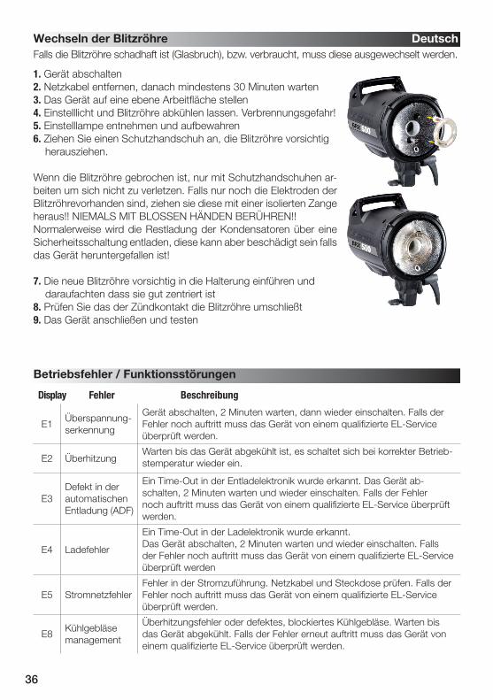
E1Überspannung-serkennung
Gerät abschalten, 2 Minuten warten, dann wieder einschalten. Falls der Fehler noch auftritt muss das Gerät von einem qualifizierte EL-Service überprüft werden.
E2 ÜberhitzungWarten bis das Gerät abgekühlt ist, es schaltet sich bei korrekter Betrieb-stemperatur wieder ein.
E3Defekt in der automatischen Entladung (ADF)
Ein Time-Out in der Entladelektronik wurde erkannt. Das Gerät ab-schalten, 2 Minuten warten und wieder einschalten. Falls der Fehler noch auftritt muss das Gerät von einem qualifizierte EL-Service überprüft werden.
E4 Ladefehler
Ein Time-Out in der Ladelektronik wurde erkannt. Das Gerät abschalten, 2 Minuten warten und wieder einschalten. Falls der Fehler noch auftritt muss das Gerät von einem qualifizierte EL-Service überprüft werden
E5 StromnetzfehlerFehler in der Stromzuführung. Netzkabel und Steckdose prüfen. Falls der Fehler noch auftritt muss das Gerät von einem qualifizierte EL-Service überprüft werden.
E8Kühlgebläsemanagement
Überhitzungsfehler oder defektes, blockiertes Kühlgebläse. Warten bis das Gerät abgekühlt. Falls der Fehler erneut auftritt muss das Gerät von einem qualifizierte EL-Service überprüft werden.
Falls die Blitzröhre schadhaft ist (Glasbruch), bzw. verbraucht, muss diese ausgewechselt werden.
1. Gerät abschalten2. Netzkabel entfernen, danach mindestens 30 Minuten warten3. Das Gerät auf eine ebene Arbeitfläche stellen4. Einstelllicht und Blitzröhre abkühlen lassen. Verbrennungsgefahr!5. Einstelllampe entnehmen und aufbewahren6. Ziehen Sie einen Schutzhandschuh an, die Blitzröhre vorsichtig herausziehen.
Wenn die Blitzröhre gebrochen ist, nur mit Schutzhandschuhen ar-beiten um sich nicht zu verletzen. Falls nur noch die Elektroden der Blitzröhrevorhanden sind, ziehen sie diese mit einer isolierten Zange heraus!! NIEMALS MIT BLOSSEN HÄNDEN BERÜHREN!!Normalerweise wird die Restladung der Kondensatoren über eine Sicherheitsschaltung entladen, diese kann aber beschädigt sein falls das Gerät heruntergefallen ist!
7. Die neue Blitzröhre vorsichtig in die Halterung einführen und daraufachten dass sie gut zentriert ist8. Prüfen Sie das der Zündkontakt die Blitzröhre umschließt9. Das Gerät anschließen und testen
Radio interference suppressiv CE-IEC 491 EN 60 555 - EN 61 000 - 4 - 2/3/4/5
Toleranzen der technischen Daten für Bauelemente und Messwerte entsprechenden IEC und EC Normen. Technische Änderungen vorbehalten. Die Werte können durch Bauelementetol-eranzen schwanken und sind als Richtwerte zu verstehen und nicht im rechtlichen Sinne als zugesicherte Eigenschaften. Keine Haftung für Druckfehler.
& Einstellicht Ein / Aus).• NEU: Test Auslöseknopf und Programmiertaste.
• NEU: Integrierter Hot-Shoe (Mittelkontakt), mit Sicherheitsverschraubung.
• SYNC-Buchse für direkten Kameraanschluss• NEU: NORMAL und SPEED Blitzsynchronisation.• Im NORMAL Modus ist der Transmitter SPEED
kompatibel mit Vorgängerversionen.• NEU: Status LED für die Batterie
Betriebsbereitschaft und Betriebsmodus.• NEU: verbessertes Batteriefach und
Funktionstasten.• NEU: Transmitter Konfigutation mit der EL-Skyport
Software 3.0 MAC / PC • Die Speed Funktion ist verfügbar für Ranger
Quadra AS, BXRi 250 / 500 und D-Lite it und für alle Geräte die mit EL-Skyport Universal SPEED verwendet werden.
Erleben und testen Sie die professionellen und leistungsstarken, neuen Funktionen des EL-Skyport Systems.Anmerkung: Auslösezeit und Reichweite werden durch Reflektionen von Decken, Wänden, Einrichtungen, im Wald bei großer Feuchtigkeit und bei Interferenzen von anderen 2.4 GHz Systemen beeinflußt. Für die optimale Funktion, sollten sich zwischen Sender und Empfänger keine Objekte befinden. Eine direkte Sicht zwischen den Modulen erhöht die Reichweite und Zuverlässigkeit.
Batterie Installation1. Ziehen Sie vorsichtig das Batteriefach heraus.2. Legen Sie die Lithium-Batterie lt. Bild. 1 polaritätsrichtig ein.3. Schließen Sie das Batteriefach.! ACHTUNG:
• Achten Sie auf richtige Polarität / Minuspol oben.• Verwenden Sie nur Lithium-Batterien CR2430 3.0 V 19372.• Entfernen Sie die Batterie, falls Sie den EL-Skyport Sender längere Zeit nicht verwenden.• Niemals die Batteriepole kurzschließen.• Vermeiden Sie direktes Sonnenlicht und große Hitze über 45°C. Batterien können explodieren.
Hot-Shoe Adapter mit SicherheitsverschraubungDer Standard Hot-Shoe Adapteranschluss mit Mittelkontakt ist mit den meisten Analog- bzw. Digitalkameras kompatibel. (Der Mittelkontakt ist der Pluspol).
Hot-Shoe mit Sicherheitsschraubver-schluss & 2.5 mmSYNC Buchse
Batteriefach
Li-Batterie (19372) Minuspol oben
Schwenkbare Antenne 360°
Bild. 1
Betriebsanleitung
Deutsch
40
FrequenzkanäleAnmerkung:
Sender und Empfänger (Universal, Transreceiver RX und die in Blitzanlagen integrierten EL-Skyport
Empfänger müssen mit der gleichen Frequenzkanaleinstellung betrieben werden!
Bild. 2
SchwenkbareAntenne 360°
Testtaster & Blitzmodus Programmierung
RX FunktionstasteLeistungserhöhungoder Pilotlicht Ein / Aus
RX FunktionstasteLeistungsreduzierung
Frequenzkanal Schalter
MODE Schalter
GROUP Schalter
FrequenzChannel
Schiebeschaltereinstellung Frequenz / Mhz1 2 3
1 (normal) Off Off Off 24562 On Off Off 24583 Off On Off 24604 On On Off 24625 Off Off On 24696 On Off On 24717 Off On On 24738 On On On 2475
Status LED
EL-Skyport SPEED und NORMAL SynchronisationsmodusDie Speed Funktion ist verfügbar für Ranger Quadra AS, BXRi 250 / 500 und D-Lite it und für alle Geräte die mit EL-Skyport Universal SPEED verwendet werden.
SPEED Modus programmieren:Synchronisiert SLR Kameras bis zu 1/250 s, und digitale Kompakt Kameras bis zu 1/2850 s. • „GROUP“ oder „ALL“ Modus einstellen.• Den TEST Schalter ca. 5 Sekunden gedrückt halten, bis die STATUS LED zweimal aufblinkt.• Testschalter danach loslassen.• Der EL-Skyport Tranmitter RX SPEED befindet sich im SPEED Modus (r.2 Modus). In diesem Modus sind nur EL-Skyport
SPEED Empfänger und die in Blitzanlagen integrierte Empfänger kompatibel.
NORMAL Modus programmierenSynchronisiert SLR Kameras bis zu 1/200 s, und digitale Kompakt Kameras bis zu 1/1600 s, abhängig vom Kameramodell. • „GROUP“ oder „ALL“ Modus einstellen.• Den TEST Schalter ca. 5 Sekunden gedrückt halten, bis die STATUS LED einmal aufblinkt.• Testschalter danach loslassen.• Der EL-Skyport Transmitter SPEED befindet sich im NORMAL Modus. Die möglichen Synchronisationszeiten verlängern
sich allerdings wird eine höhere Reichweite erzielt.Transmitter SPEED Modulkonfiguration mit der EL-Skyport Software Nur möglich mit der PC / MAC EL-Skyport Softwareversion 3.0 und höher, zusätzlich wird der EL-Skyport USB Transceiver RX benötigt:
• Individuell programmierbarer oder abschaltbarer Batterie Timer (Energiesparmodus).• Auslöseverzögerung von 256 Mikrosekunden bis zu 15 Sekunden einstellbar.
(250 Mikrosekunden entsprechen 1/4000 Sekunde).• Die EL-Skyport Software kann kostenfrei von www.elinchrom.com geladen werden.
Deutsch
41
Transmitter Speed Konfigurationsmodus für die EL-Skyport Software einstellen• Den Transmitter ausschalten.• „TEST“ Taster drücken und halten während das Modul eingeschaltet wird.• Den „TEST“ Taster solange drücken bis die STATUS LED aufleuchtet.> Beachten Sie die Informationen und Hinweise für die Modulkonfiguration in der EL-Skyport PC / MAC Software 3.0. Zusätzlich wird der EL-Skyport USB Transceiver RX benötigt.
BlitzauslösungDer EL-Skyport Transmitter SPEED kann für folgende Auslösebetriebsarten konfiguriertwerden:• OFF – Transmitter ist ausgeschaltet.• GROUP – Auswahl der Gruppen 1 - 4 > Alle korrespondierenden EL-Skyport Empfänger lösen bei gleicher Gruppeneinstellung 1 - 4 aus.• ALL – Aktiviert alle Gruppen 1 - 4. > Alle EL-Skyport Empfänger lösen aus, unabhängig welche Gruppe eingestellt wurde.
Hot-Shoe mit integrierter SYNCHRON Buchse 2.5 mm
Über die im Hot-Shoe integrierte 2.5 mm Mono Synchronisationsbuchse kann der Transmitter SPEED direkt mit dem Kamera X-Kontakt verbunden werden. Das benötigte Synchronisationskabel ist im EL-Skyport Set enthalten.
EL- Skyport Transmitter RX FunktionenKompatibel mit Ranger RX, Style RX, Digital RX, BXRi 250 / 500, Ranger Quadra AS!Wenn der EL-Skyport Transmitter SPEED mit dem EL-Skyport Transceivers RX, BXRi 250 / 500 oder dem Ranger Quadra AS betrieben wird, stehen folgende EXTRA Funktionen bei RX Blitzgeräten zur Verfügung:
Bei Gruppeneinstellungen 1-4 werden nur RX Geräte innerhalb einer Gruppe angesprochen. Wird der Transmitter SPEED auf ALL eingestellt, werden alle in Reichweite befindlichen RX Geräte fernbedient.
1. Leistungserhöhung in 1/10 Blendenstufen
• Mit der Taste + (plus) kann die Leistungseinstellung der selektierten Gruppe (oder aller) RX-Geräte um 1/10 Blendenwerte erhöht werden.
2. Leistungsreduzierung in 1/10 Blendenstufen
• Mit der Taste – (minus) kann die Leistungseinstellung der selektierten Gruppe (oder aller) RX-Geräte um 1/10 Blendenwerte reduziert werden.
3. Pilotlichteinstellungen
• wird die Taste + länger als 2 Sekunden gedrückt und dann losgelassen, wird das Einstellicht ein- bzw. ausgeschaltet.
EL- Skyport Speed Funktionen
Batterie Energiesparmodus / Power Save Timer• Wird der Transmitter SPEED 30 Minuten lang nicht benutzt schaltet sich das Gerät in den Energiesparmodus. Zur
Reaktivierung den „Test“ Schalter einmal drücken.• Die werkseitigen Timereinstellungen können mit der EL-Skyport Software für MAC / PC Version 3.0 oder höher
konfiguriert werden. (Zusätzlich benötigt wird der EL-Skyport USB Transceiver RX)
LED Stausanzeige
• LED blinkt einmal alle 4 Sekunden: Der Transmitter Speed befindet sich im NORMAL Modus.• LED blink zweimal alle 4 Sekunden: Der Transmitter Speed befindet sich im SPEED Modus.• LED Helligkeit richtet sich nach dem Ladezustand der Batterie. Wenn die LED nicht, oder nur schwach leuchtet, bitte
die Batterie erneuern. • LED leuchtet nicht: Der Transmitter Speed wurde abgeschaltet oder befindet sich im Energiesparmodus.
Auf Werkseinstellung zurücksetzen / RESET• Transmitter SPEED einschalten.• Den „Test“ Taster mindestens 10 Sekunden gedrückt halten.
Deutsch
42
EL-Skyport ModuleEL-Skyport Universal SPEED (NEU) / Universal (vorgänger Version) • Universal Receiver ist ein universeller Empfänger für nahezu alle Blitzgeräte, die mit einer normkonformen SYNCHRON Buchse ausgestattet sind.EL-Skyport Transceiver RX • Dieser Transceiver ist nur für Elinchrom RX Geräte. Alle Einstellungen und die Blitzauslösung, können mit der EL-Skyport Software eingestellt und kontrolliert werden. EL-Skyport USB RX SPEED (NEU) / USB RX (vorgänger Version) • Erlaubt die Fernbedienung aller Elinchrom RX Geräte per Computer in Verbindung mit Transceiver RX Modul.
FehlerbehandlungPrüfen Sie beim Auftreten von Problem folgende Punkte:
Haben Sie dieses Problem? Bitte prüfen Sie genannte Punkte:
Keine Blitzauslösung aller Geräte durch den TransmitterMode “All” ist selektiert
Ø Ist der Transmitter eingeschaltet.Ø Prüfen Sie die Polarität der Batterie.Ø Prüfen Sie den korrekten Anschluss des Empfängers.Ø Prüfen Sie die korrekte Frequenzkanaleinstellung.Ø Prüfen, ob sich Transmitter und Empfänger im gleichen Auslösemodus SPEED oder NORMAL befinden.
Einige Blitzgeräte werden nicht ausgelöstMode “Grp” ist selektiert
Ø Prüfen Sie die korrekte Gruppenkanaleinstellung.Ø Verringern Sie den Abstand.
TEST Auslösung geht, aber keine Auslösung durch die Kamera
Ø Korrekte Verbindung zum Hot-shoe prüfen.Ø Verwenden Sie ein SYNC Kabel anstelle der Hot-shoe Verbindung.
Die Reichweite ist zu gering Ø Plazieren Sie Ihr Blitzlichtgerät anders.Ø Größerer Abstand zu Wänden und Decke.Ø Ändern Sie die Ausrichtung der Antenne von Transmitter und Receiver/Transceiver.Ø Benutzen Sie ein RX Verlängerungskabel um die Distanz zu verringern.
Deutsch
Universal Speed& Universal
Transceiver RX19353
USB RX Speed& USB RX
43
CE-Kennzeichnung
Dieses Gerät erfüllt in der ausgelieferten Ausführung die Anforderungen der EG Richtlinie 89/336/EWG „Elektromagnetische Verträglichkeit“ und 73/23/EWG “Niederspannungsrich-tlinie” und die Richtlinie nach R&TTE 99/5/EC
Entsorgung und Recycling
Dieses Gerät wurde weitestgehend aus Materialien hergestellt, die umweltschonend entsorgt und einem fachgerechten Recycling zugeführt werden können. Nach seinem Gebrauch wird das Gerät zurückgenommen, um es einer Wiederverwertung bzw. wertstofflichen Verwertung zuzuführen, soweit es in bestimmungsgemäßen Gebrauch entspricht. Nicht verwertbare Geräteteile werden sachgemäß entsorgt. Bei Fragen zur
Entsorgung wenden Sie sich bitte and Ihre Verkaufsstelle. Eine Liste aller Verkaufsstellen in Ihrer Nähe finden Sie auf unserer Homepage www.elinchrom.com.
Deutsch
44
P.S: les informations contenues dans ce manuel peuvent faire l’objet de modifications sans préavis.
Introduction 45
Déclaration de conformité, recyclage, certification CE 46
Prescriptions de sécurité 47
Fonctions de base et fonctions programmables avancées 48
Avant de commencer / Interrupteur et fusible 49
Description des commandes 50
Fonctions programmables - Reset 51
Lampe pilote - configuration des modes 51
Affichage numérique multifonctions 52
Prise de synchronisation, bouton test 52
Configuration de l’Eye Cell 53 - 54
Signal acoustique de charge – configuration 55
EL-Skyport – utilisation et configuration 56
Remplacement du tube flash / Affichage des pannes 57
Caractéristiques techniques 58
EL-Skyport Transmitter Speed Mode d’emploi 59-64
Garantie 128-130
Table des matières Français
45
Les appareils compacts BRX sont développés par Elinchrom SA (LTD) – Suisse.Elinchrom n’utilise que des composants de haute qualité et testés pour la fabrication de ses appareils. Le contrôle final assure le maintien des normes de qualité pour garantir un fonc-tionnement sans défaut. Nous espérons que vous serez pleinement satisfaits de cet appareil. Nous vous prions de vous conformer aux présentes instructions et aux prescriptions de sécurité. Ainsi vous obtiendrez les résultats que vous attendez de votre appareil et vous assurerez son fonctionnement pour longtemps.
Flash compact BRX 250 / BRX 500
Cet équipement a fait l’objet de tests et a été déclaré conforme aux limites auxquelles sont soumises les appareils numériques de la classe B, conformément à la section 15 de la réglementation FCC, il n’émet pas de perturbation radioélectrique dépassant les limites prescrites dans le règlement sur le brouillage édicté par leministère des communications du Canada. Ces limites ont été fixées afin d’apporter une protection raisonnablecontre les perturbations pouvant survenir sur une installation domestique. Cet équipement peut émettre del’énergie de fréquences radio et pourrait, s’il n’est pas installé et utilisé en conformité avec les instructions,perturber la réception des ondes radio. Cependant, il n’est pas garanti qu’une installation domestique nesoit pas perturbée par des interférences. Si cet équipement provoque des interférences lors de réceptiond’ondes radio/TV, vérifiables en mettant l’équipement hors tension puis sous tension, l’utilisateur est invité àprendre une ou plusieurs des mesures suivantes pour tenter de supprimer cet inconvénient :• Réorienter ou déplacer l’antenne réceptrice de la radio/TV.• Augmenter la distance qui sépare l’équipement perturbateur du récepteur radio/TV.• Brancher l’équipement dans une prise de courant d’un circuit différent de celui sur lequel lerécepteur est raccordé.• Demander l’aide du revendeur ou d’un technicien expérimenté en radio/ TV.Elinchrom S.A (LTD) ne peut être tenu pour responsable des perturbations radioélectriques, du remplacement ou du branchement de câbles de raccordement et d’équipements autres que ceux qui sont mentionnés et fournis par Elinchrom S.A (LTD) La substitution ou un raccordement non autorisé relèveront de la seule responsabilité de l’utilisateur.
Déclaration de conformité à la classe B FCC / USA
Introduction Français
46
SymbolesSignification des symboles utilisés dans ce manuel.Soyez particulièrement attentif aux prescriptions impératives indiquées par ce symbole. Leur non respect peut mettre en danger votre vie, peut détruire l’appareil ou e dommager tout autre équipement.
!
Cet appareil est conforme aux règles FCC, paragraphe 15. Son exploitation est soumise aux deux conditions suivantes: 1. Cet appareil ne doit pas provoquer d’interférences nuisibles.2. Cet appareil doit supporter les interférences extérieures, notamment celles susceptiblesd’engendrer un dysfonctionnement.
Nom du produit : BRX 250 / BRX 500
Marque : ELINCHROM
Référence : 20440.1 / 20441.1
Responsable : Elinchrom LTD / Av. De Longemalle 11 / 1020 Renens / Switzerland
Téléphone : +41 21 637 26 77
Fax: +41 21 637 26 81
Nous, Elinchrom S.A (LTD), certifions par la présente que l’équipement de marque et de ré-férence tel que spécifié ci-dessus, a été testé conformément aux règles FCC en vigueur, selon les normes et mesures précises et que toutes les démarches nécessaires ont été effectuées et sont mises en oeuvre pour garantir que l’unité de production de ce produit continue à satisfaire les exigences requises. La version de ce flash est conforme aux spécifications et exigences des directives CEE 89/336/EEC “Compatibilité électromagnétique”et 73/23/EEC “Directives basse tension”.
Déclaration de conformité Français
Certification CEM pour l’EL-SkyportCe module de communication intégré est conforme aux spécifications et exigences des directives CEE 89/336/EEC “Compatibilité électromagnétique”, 73/23/EEC “Directives basse tension”, et R&TTE 99/5/EC.
Certification CELa version de ce flash est conforme aux spécifications et exigences des directivesCEE 89/336/EEC “Compatibilité électromagnétique” et 73/23/EEC “Directives basse
tension”.
Élimination et recyclageCe symbole apposé sur le produit ou sur son emballage indique que ce produit ne doit pas être jeté avec les déchets ménagers ordinaires. Cet appareil a été presque entièrement fabriqué à partir de matériaux dont l’élimination est respectueuse de
l’environnement et dont le recyclage peut être assuré de manière appropriée. En fin de vie, l’appareil sera remis dans un centre de collecte et de tri de déchets électriques ou repris par le revendeur qui le recyclera ou en récupérera les matières premières. Pour toute question relative à l’élimination, renseignez-vous auprès de votre revendeur le plus proche dont la liste figure sur notre site www.elinchrom.com.
47
!
• Transportez si possible le matériel dans son emballage d’origine ou dans un emballage adapté (sac rembourré ou valise) de manière à le protéger des chocs et secousses.• Le transport de l’appareil ne doit se faire que quand il est déchargé. Attendez au moins 30 minutes avant de l’emballer et de le transporter• Évitez d’exposer l’appareil à des variations brusques de température qui pourraient engen drer de la condensation.• Ne laissez jamais tomber l’appareil, le tube éclair pourrait se casser.
Câble d’alimentationPour garantir un fonctionnement fiable, employez le câble d’origine.• Le câble d’alimentation livré est certifié conforme HAR ou VDE.• Le courant fourni par la prise doit correspondre à celui de l’appareil.• N’utilisez pas de prise multiple pour alimenter plusieurs flashs sur une même prise murale. Répartissez-les sur plusieurs prises séparées.
• Les flashs électroniques accumulent une importante énergie électrique dans des condensateurs sous forme de haute tension.• Pour votre sécurité, n’ouvrez ni ne démontez jamais votre flash.• Seul un agent agréé Elinchrom peut effectuer des réparations sur un flash.• Si votre flash est défectueux, ne tentez pas de le réenclencher.• N’allumez pas le flash s’il n’est pas équipé d’une ampoule ou d’un tube àéclairs, en raison de la haute tension des éléments de contact! Danger de mort!
Conformément aux précautions de sécurité, nous attirons votre attention sur le fait que ce flash électronique n’a pas été conçu pour être utilisé à l’extérieur par mauvais temps, dans une ambi-ance humide ou poussiéreuse, dans des conditions climatiques extrêmes (froid/chaud) pouvant provoquer de la condensation. Le flash sera raccordé au secteur alternatif sur une prise munie d’un conducteur de protection (mise à terre).Prendre garde de ne jamais introduire un quelconque objet par les ouïes de ventilation. Bien que débranché du secteur, ce flash peut conserver dans ses condensateurs une charge dangereuse pendant un temps très long.• Ne pas utiliser dans une zone confinée (hôpital, etc.)• Ne pas utiliser dans une zone à risque d’explosion• Ne jamais laisser d’enfants sans surveillance à proximité• N’utiliser que des accessoires Elinchrom originaux.
• En utilisation, le tube flash et l’ampoule sont brûlants!• Déconnectez le flash du secteur et attendez min. 30 minutes avant de remplacer le tube flash, la lampe pilote ou un fusible.• Ne déclenchez pas le flash si une personne se trouve à moins d’un mètre de la torche et ne regardez jamais directement l’éclair.• N’utilisez pas ce flash à proximité de matériaux ou produits inflammables.• Avant le premier allumage, vérifiez que le voltage de la lampe pilote soit correct.
Prescriptions de sécurité Français
Transport
Tube flash et lampe pilote
48
Fonctions de base Français
Fonctions avancées programmables
Les fonctions de base sont faciles d’utilisation et semblables à celles des flashes Elinchrom de générations précédentes.
Toutes les nouvelles fonctions peuvent être personnalisées par l’utilisateur. La configuration d’usine (par défaut) peut être rétablie à tout moment. Suivez soigneusement les instructions pour configurer ces nouvelles fonctions.
La fonction VFC éteint la lampe pilote durant la recharge, après le déclenchement du flash. L’utilisateur peut ainsi contrôler que tous les flashes du studio ont été déclenchés. On peut améliorer encore la surveillance avec le signal sonore de charge.
Fonction VFC (Visual-Flash-Control)
Cette fonction permet de réduire d’un diaphragme ( -1 f-sop) la lampe pilote lors de l’utilisation de flashes de différentes puissances (par ex. : 250 & 500 Ws) pour assurer un meilleur contrôle.
Fonction PMS (Proportional-Modelling lamp-Set up)
Certains appareils de photo produisent des pré-flashes pour réduire l’effet des yeux rouges ; ceux-ci peuvent déclencher le flash principal trop tôt. Pour éviter cette erreur de synchronisa-tion, la « cellule intelligente » Elinchrom possède un « Mode automatique » qui détecte les pré-flashes de l’appareil de photo. En « Mode manuel », on peut aussi introduire le nombre de pré-flashes à ignorer avant le flash principal.
Mode manuel & automatique de la cellule photo-électrique
L’utilisateur peut choisir la durée du signal de charge entre 0,1 s et 0,5 s.Configuration du signal sonore de charge
La commande radio EL-Skyport intégrée permet le déclenchement, le réglage de la puis-sance et l’enclenchement de la lampe pilote ; elle requiert un transmetteur EL-Skyport.Les « groupes » et les « canaux de fréquence » peuvent être paramétrés pour chaque appareil BRX.
Commande et déclenchement sans fil par EL-Skyport
Ordinairement, les échelons de puissance du flash et de la lampe pilote sont réglés par 1/10 de diaphragme. Ceux-ci peuvent être modifiés de 1/10 à 7/10 ou d’un diaphragme.
Configuration des échelons de puissance du flash et de la lampe pilote
Le ventilateur de refroidissement s’enclenche automatiquement lorsque l’appareil chauffe. Le microcontrôleur commande le ventilateur, surveille sa rotation et la température de l’appareil. S’il détecte un échauffement excessif, il bloque la charge en affichant l’erreur « E8 ».
Gestion de la température par commande du ventilateur
• Réglage de la puissance de l’éclair par touche « Haut » / « Bas »• Réglage de l’intensité de la lampe pilote par touche « Haut » / « Bas »• Mode proportionnel / indépendant / éteint de la lampe pilote• Enclenchement / déclenchement de la cellule photo-électrique• Enclenchement / déclenchement du signal acoustique de charge• Touche de test de l’éclair• Prise de synchronisation pour « jack » 3.5mm• EL-Skyport intégré pour déclencher le flash et commander les fonctions de bases.
49
Les unités BRX sont multi-tensions, elles s’adaptent à tous les réseaux électriques de 90 à 260V/50 - 60Hz. Avant la mise sous tension, vérifiez que la tension de la lampe pilote corresponde à celle de votre réseau. L’unité doit toujours être reliée à une prise avec terre de protection.Tous les appareils BRX sont munis de la bague à baïonnette Elinchrom qui accepte tous les réflecteurs et accessoires de la gamme Elinchrom.Montez toujours l’appareil sur un trépied ou un support adapté.Enlevez la protection noire AVANT toute utilisation du flash.
1. Assurez-vous que la lampe pilote ait la bonne tension2. Laissez déclenché l’interrupteur secteur (2) (position noire)3. Insérez le cordon d’alimentation livré dans la prise de l’appareil (1) puis reliez-le à une prise secteur avec terre de protection.4. Enclenchez l’appareil en basculant l’interrupteur (position rouge).5. Branchez le cordon synchro sur la prise synchro (5)6. Choisissez la puissance avec les touches de réglage (10)
Mise en marche
(A) Bague de blocage
Poignée
(C) Levier d’inclinaison de l’appareil et de fixation pour un parapluie supplémentaire.
(B) Capuchon de protection (26124)
Avant de commencer Français
Interrupteur et fusible
Alimentation réseau
Fusible de l’appareil
Fusible de la lampe pilote
N’utilisez que le cordon secteur original Elinchrom. Déclenchez l’appareil avant de le brancher ou de le débrancher.
N’utilisez qu’un type adapté : 5 x 20 mm - 8AT, « T » pour déclanchement retardé (code 19022 / 10pces) pour le BRX 250 et 500. Remarque : avant de remplacer un fusible, déclen-chez l’appareil et retirez le cordon secteur. Ouvrez le petit tiroir à côté du bloc de la prise secteur au moyen d’un fin tournevis ; remplacez le fusible défectueux par celui de réserve logé dans la poignée (N.B. : contrôlez la valeur correcte du calibre).
N’utilisez qu’un type adapté : 5 x 20 mm - 2.5AF, « F » pour rapide (code 19033 / 10pces).Remarque : avant de remplacer un fusible qui a sauté, déclenchez l’appareil et retirez le cor-don secteur. Dévissez le porte-fusible situé sur le panneau arrière au moyen d’un tournevis ; remplacez le fusible défectueux par celui de réserve logé dans la poignée (N.B. : contrôlez la valeur correcte du calibre). N’utilisez qu’un fusible à coupure rapide « F » qui protègera lecircuit de commande de la lampe pilote.
50
1. Prise secteur de l’appareil ; comprend le fusible de l’appareil.2. Interrupteur secteur ON/OFF3. Fusible de la lampe pilote (rapide !)4. Bouton de test du flash5. Prise synchro « jack » de 3,5 mm pour le signal de synchro 5V6. Affichage multifonctions avec indication de charge / décharge7. Enclenchement / déclenchement du signal acoustique de charge ; programmable*8. Enclenchement / déclenchement de la cellule photo-électrique de déclenchement ; programmable*9. Cellule photo-électrique déclenchement.
10. Touche HAUT & BAS de réglage de la puissance du flash ; touches de défilement pour les valeurs des fonctions programmables*.11. Lampe pilote, modes proportionnel / indépendant / déclenché ; programmable*12. Touche HAUT & BAS de réglage de l’intensité de la lampe pilote et d’enclenchement du mode indépendant.13. Levier d’inclinaison de l’appareil et de fixation pour un parapluie supplémentaire14. Poignée avec logement pour les fusibles de rechange15. Logement 5/8” pour trépied standard16. Tube central pour le montage des parapluies EL de 7 mm de diamètre17. Bouton moleté de blocage sur le pied
Description des commandes Français
Ces touches du panneau de commande ont des fonctions spéciles de paramétrage t de configuration,enparticulier de la télécommande intégrée EL-Skyport. Ces fonctions sont détaillées ci-après.
Les fonctions avancées programmables permettent à l’utilisateur de personnaliser certaines fonctions de son BRX. Lisez attentivement les instructions ci-après.Votre BRX est configuré en usine avec les modes et les paramètres les plus couramment utilisés. Ces valeurs par défaut peuvent être rétablies à tout moment (reset) :1. Eteignez l’appareil2. Pressez simultanément les touches « Haut » et « Bas » de réglage de la puissance3. Allumez l’appareil « r.1 » clignote rapidement sur l’affichage.
• Intensité proportionnelle à la puissance du flash• Réglage indépendant de la puissance du flash• Déclenchement de la lampe pilote• Fonction VFC (Visual-Flash-Control) d’extinction de la lampe pilote durant la recharge• Fonction PMS (Proportional-Modelling lamp-Set up) pour adapter l’intensité pour les ap-pareils 250 et 500 Ws.
Configuration des modesModes proportionnel / indépendant / déclenché• Pressez séquentiellement la touche « Free/Prop » pour allumer ou éteindre la lampe en mode « proportionnel », la LED « Prop » s’allume. • Pressez la touche « Haut » ou « Bas » de réglage de l’intensité de la lampe pilote pour acti-ver le mode « indépendant », la LED « Free » s’allume. Presser la touche « Haut » ou « Bas » pour régler l’intensité voulue.• Pressez la touche « Free/Prop » pour éteindre la lampe.
Mode VFC (Visual Flash Control)(Extinction de la lampe pilote durant la recharge)1. Pressez la touche “Free/Prop” plus de 2 secondes jusqu’à l’affichage de “F.x” où x = 1 ou 02. Pressez la touche « HAUT » ou la touche « BAS » de réglage de la puissance : • “F.0”: mode VFC = OFF. La lampe pilote reste allumée après le flash. • “F.1”: mode VFC = ON. La lampe pilote s’éteint durant la recharge.3. L’affichage revient en mode normal après env. 4 secondes si aucune touche n’est pressée. La sélection est automatiquement sauvegardée.4. La sélection par défaut est “F.0”, VFC = OFF.
52
La puissance du flash ou de la lampe pilote sont affichées dans le format identique au dia-phragme, de 2.3 à 6.3 pour le BRX 500. La différence, par exemple entre 5.3 et 6.3, est d’un diaphragme. 5 diaphragmes peuvent être réglés par pas de 1/10 diaphragme. L’échelon peut être personnalisé, par exemple par pas de 5/10 ou d’une autre valeur.
Durant la charge ou la décharge, l’affichage clignote tant que la puissance n’est pas disponible. En cas d’erreur ou de surchauffe, l’affichage indique l’erreur « E.x », où x est le code de l’erreur.
Affichage du BRX 500 2.3 3.3 4.3 5.3 6.3
Joules / Ws 31 62.5 125 250 500
Remarque : les BRX 250 et BRX 500 disposent d’un système de décharge interne lors de la réduction de puissance. Pour éviter la surchauffe lors de décharges fréquentes, vous pouvez déclencher le flash par la touche test.
Affichage numérique multifonctions
Prise de synchronisation
Bouton test flash
En mode standard, la cellule de déclenchement déclenche le flash en recevant à distance un autre flash. Elle est spécialement conçue pour fonctionner dans une ambiance de studio. Un éclairage direct ou toute autre source de lumière intense peut réduire sa sensibilité.Les appareils de photos avec flash intégré et dispositif anti-yeux rouges déclencheraient le flash au premier pré-flash. La cellule peut détecter automatiquement les pré-flashs et les ignorer. On peut aussi introduire manuellement les paramètres des pré-flashs.
Eye Cell, Cellule de déclenchement « intelligente »
La touche de Test permet de déclencher le flash manuellement. La LED verte se rallume dès que l’appareil est rechargé.Si la LED verte ne se rallume pas, le système de charge peut être en cause. Contactez un agent agréé Elinchrom.
Bouton test flash (4)
5
Sync
Le BRX est équipé d’une prise standard mini-jack 3,5 mm.N’utilisez que les cordons synchro d’Elinchrom. Ne reliez pas en paral-lèle votre BRX avec d’autres installations. Elinchrom utilise une tension de 5V isolée pour protéger les appareils de photo.
Mode PMS (Proportional-Modelling lamp-Set up)
1. Presser la touche “Free/Prop” plus de 2 secondes jusqu’à l’affichage de “F.x”2. Presser sitôt après encore une fois la touche “Free/Prop”, « -.x » est affiché, où x = 1 ou 03. Presser la touche « HAUT » ou la touche « BAS » de réglage de la puissance : a. “-.0”: mode PMS = OFF. La lampe pilote est réglée au maximum. b. “-.1”: mode PMS = ON. La lampe pilote est réduite d’un diaphragme.
(Lors de l’utilisation d’appareils de puissance maximum 250J ou 500J)
53
Pressez la touche « Cell » moins de ½ seconde pour enclencher ou déclencher la cellule.Visualisation de la LED :• LED allumée : cellule active. Le flash se déclenche dès que la cellule reçoit un éclair.• LED éteinte : cellule inactive
Pressez la touche cellule environ 2 secondes jusqu’au clignotement de la LED.Visualisation de la LED :• LED clignotant rapidement : fonction pré-flash activée.• LED éteinte : cellule inactive
Configuration de l’Eye Cell Français
1. Presser la touche « Cell » 4 secondes jusqu’à l’affichage de « c.x » (« x » correspond au nombre de pré-flashes, flash principal compris, de 1 à 7).2. Incrémenter / décrémenter avec la touche de puissance « HAUT » / « BAS » pour afficher « c.0 ».3. Faire un test avec l’appareil de photo en mode pré-flash: la cellule du BRX comptera le nombre de pré-flashs envoyés par l’appareil et le mémorisera.4. Le BRX est maintenant prêt à fonctionner dans ce mode.Attention!: Si vous avez pressé trop longtemps la touche « Cell », vous obtiendrez l’affichage « t.4 » ou « b.1 ». Attendez quelques secondes que l’affichage revienne au mode standard (voir § 4 ci-après).
Modes de la cellule1. Mode standard.2. Mode pré-flashes. Les paramètres sont introduits de différentes manières :a. Reconnaissance automatique des pré-flashes pour une synchronisation correcte.b. Introduction manuelle des pré-flashes pour une synchronisation correcte.c. Choix des durées du mode pré-flash. Seulement pour utilisateurs avertis.
3. Configuration de la cellule en mode pré-flash automatique « c.0 »
1. Utilisation de la cellule en mode standard
2. Activation de la cellule en mode pré-flash
1. Pressez la touche « Cell » environ 4 secondes jusqu’à l’affichage de « c.x » (« x » corre-spond au nombre de pré-flashes, flash principal compris, de 1 à 7).2. Incrémentez / décrémentez avec la touche de puissance « HAUT » / « BAS » pour afficher le nombre de pré-flashes désirés (y compris le flash principal).3. L’affichage retourne au mode normal après env. 4 secondes si aucune touche n’est pres-sée ; la valeur introduite est alors mémorisée. La LED de la cellule clignote pour montrer que le mode est actif.4. Répétez les étapes ci-dessus pour visualiser le nombre de pré-flashes introduits.
4. Configuration de la cellule en mode pré-flash manuel
54
Valeur « t » 1 2 3 4 5 6 7 8
Temps en seconde 1 2 3 4 5 6 7 8
Configuration:1. Pressez la touche « Cell » environ 6 secondes jusqu’à l’affichage de « t.x », où « x » a une valeur de 1 à 8.2. Pressez la touche « Cell » pour passer de « t.x » à « b.x »3. Pressez la touche de puissance « HAUT » / « BAS » pour changer de valeur. Les valeurs par défaut sont : a. « t.4 » (durée de la fenêtre de temps des pré-flashes ) b. « b.1 » (temps minimum entre 2 pré-flashes )4. L’affichage retourne au mode normal après env. 4 secondes si aucune touche n’est pres-sée ; la valeur introduite est alors mémorisée.
« x » correspond à la durée de détection des pré-flashes, y compris le flash principal. A ne changer que si la séquence des pré-flashes est plus longue que celle introduite par défaut.Choisir « x » entre « 1 » et « 8 » pour que tous les pré-flashes soient inclus dans la durée de détection.
(Seulement pour les appareils équipés de LED anti yeux rouges)« x », valeur entre « 0 » et « 7 », qui fixe le délai entre 2 pré-flashes.
N’utilisez cette possibilité que si la détection automatique des pré-flashes ne donne pas satisfaction (par exemple si le délai des pré-flashes est trop court ou que les LEDs sont mal détectées).
Valeur « b» 0 1 2 3 4 5 6 7
Temps en millième de seconde 0 2 4 6 8 10 12 14
5. Configuration des paramètres t et b des pré-flashes
Configuration de la fenêtre de temps « t.x »
Configuration de la durée entre 2 pré-flashes « b.x »
!
55
Valeur « A » 1 2 3 4 5 6 7
Durée en millième de seconde 70 140 210 280 350 420 490
Sélection du signalPressez la touche « Audio » moins de ½ seconde pour enclencher ou déclencher le bip.• LED allumée : le bip est activé• LED éteinte : le bip est désactivé
Modifier la durée du beep1. Pressez la touche « Audio » environ 2 secondes jusqu’à l’affichage de « A.x », où « x » a une valeur de 1 à 7.2. Pressez la touche de puissance « HAUT » / « BAS » pour changer de valeur. La valeur par défaut est « A.3 ». 3. L’affichage retourne au mode normal après env. 4 secondes si aucune touche n’est pres-sée ; la valeur introduite est alors mémorisée.Choisissez une valeur entre « 0 » et « 7 » pour fixer la durée du bip :
En différenciant la durée du bip de charge pour les différents appareils, on peut mieux identi-fier la fin de leur charge respective.
Signal acoustique de charge – configuration Français
56
EL-Skyport – utilisation et configuration Français
Configurer le groupe
Configurer le canal
Configuration de l’échelon de puissance
Activation de l’EL-Skyport
L’enclenchement / déclenchement, le groupe, le canal et les échelons de puissance peuvent être configurés.
Pressez simultanément les touches puissance « HAUT » / « BAS » pour configurer les fonc-tions avancées.Affichage Changer de valeur avec la touche puissance « HAUT » / « BAS »r.0 EL-Skyport offr.1 EL- Skyport on (configuration par défaut)r.2 EL-Skyport mode rapide (Seulement avec EL-Skyport Speed)Les réglages sont mémorisés et l’affichage retourne au mode normal après env. 4 secondes si aucune touche n’est pressée.
1. Pressez simultanément les touches puissance « HAUT » / « BAS » pour configurer les fonc-tions avancées.2. Pressez la touche « Prop/Free » jusqu’à afficher « G.x »Affichage Changer de valeur avec la touche puissance « HAUT » / « BAS »G.1 Groupe 1 (configuration par défaut)G.2 Groupe 2G.3 Groupe 3G.4 Groupe 4Les réglages sont mémorisés et l’affichage retourne au mode normal après env. 4 secondes si aucune touche n’est pressée.
Ne modifiez le canal que si le BRX interfère avec d’autres appareils.1. Pressez simultanément les touches puissance « HAUT » / « BAS » pour configurer les fonc-tions avancées.2. Pressez la touche « Prop/Free » jusqu’à afficher « F.x »Affichage Changer de valeur avec la touche puissance « HAUT » / « BAS »F.1 to F.8 Sélectionnez le canal de fréquence de 1 à 8 qui correspond au transmetteur EL-Skyport ; le canal par défaut est « F.1 ». Les réglages sont mémorisés et l’affichage retourne au mode normal après env. 4 secondes si aucune touche n’est pressée.
1. Pressez simultanément les touches puissance « HAUT » / « BAS » pour entrer dans le mode de configuration des fonctions avancées.2. Pressez la touche « Prop/Free » jusqu’à afficher « i.1 » Affichage Changer de valeur avec la touche puissance « HAUT » / « BAS »i.0 +/- 1 diaphragme i.1 +/- 1/10 diaphragme (configuration par défaut)i.2 +/- 2/10 diaphragmei.3 +/- 3/10 diaphragmei.4 +/- 4/10 diaphragmei.5 +/- 5/10 diaphragmeLes réglages sont mémorisés et l’affichage retourne au mode normal après env. 4 secondes si aucune touche n’est pressée.
57
Si l’appareil ne flashe plus, bien que l’interrupteur ON / OFF indique que l’appareil soit sous tension, il est probable que le tube éclair doive être remplacé. Remarque : les tubes flash ont une longue durée de vie en usage normal. Néanmoins, de longues séquences de flashs rapides peuvent surchauffer les électrodes conduisant à une usure prématurée.
Pour remplacer le tube1. Déclenchez l’interrupteur principal2. Débranchez le câble d’alimentation3. Enlevez l’appareil de son support et le placer sur un plan horizontal stable. Attention! Le tube éclair et la lampe pilote peuvent être brûlants. Attendez au moins 30 minutes avant toute manipulation du tube éclair.4. Enlevez le réflecteur et la lampe pilote et mettez-les en lieu sûr5. Utilisez un gant de protection pour tirer prudemment sur le tube. S’il est cassé, utilisez impérativement une pince isolante pour extraire les électrodes. Ne touchez jamais les électrodes à mains nues et sans outil isolé électriquement.6. Assurez-vous que le contact du trigger soit en place avant d’insérer le nouveau tube avec le gant de protection livré7. Contrôlez que le tube soit bien centré et enfoncé dans les bornes et que le trigger soit en place.8. Rebranchez l’appareil et l’essayer.
Remplacement du tube flash Français
Affichage des pannes
E1Détection surtension
Déclenchez l’appareil et attendre 2 minutes avant de le réenclencher. Si l’erreur persiste, l’appareil doit être apporté à un service agréé par Elinchrom
E2 SurchauffeAttendre que l’appareil soit refroidi. L’erreur disparaîtra et l’appareil sera à nouveau opérationnel.
E3Défaut de l’unité de décharge
Le temps de décharge a dépassé la durée normale. Déclenchez l’appareil et attendre 2 minutes avant de le réenclencher. Si l’erreur persiste, l’appareil doit être apporté à un service agréé par Elinchrom.
E4Défaut de charge
Le temps de charge a dépassé la durée normale. Déclenchez l’appareil et attendre 2 minutes avant de le réenclencher. Si l’erreur persiste, l’appareil doit être apporté à un service agréé par Elinchrom.
E5Défaut de l’alimentation secteur
L’appareil a détecté un défaut d’alimentation. Contrôlez le câble et la prise secteur. Déclenchez l’appareil et attendre 2 minutes avant de le réenclencher. Si l’erreur persiste, l’appareil doit être apporté à un service agréé par Elin-chrom.
E8
Défaut du système de refroidisse-ment
L’appareil a détecté un blocage du ventilateur ou un refroidissement insuffisant. Attendre que l’appareil se soit refroidi. Si l’erreur se reproduit, l’appareil doit être apporté à un service agréé par Elinchrom.
Défaut Solutions
58
Énergie de l’éclair J(Ws) 250 500
Tension réseau V 90/260 90/260
Diaphragme, 1m, 100 ISO, avec réflecteur 48°
64 90
Plage de réglage de l’énergie J(Ws) 16-250 31-500
Plage de réglage des diaphragmes phragme 5 diaphragmes 1/16 - 1/1
Temps de recharge, min./max. (230 V) s 0.29 / 0.73 0.36 / 1.13
Temps de recharge, min./max. (115 V) s 0.27 / 1.02 0.34 / 1.45
Temp. de couleur à puissance max. °K 5360 5410
Durée de l’éclair @ (t 0,5) 1/1 s 1/2762 1/1558
Durée de l’éclair @ (t 0,5) 1/16 s 1/2165 1/1395
Stabilité de la régulation de tension 0.5 % ± 0.5 %
Tension de synchronisation V 5
Tube éclair embrochable N° 24000 24000
Lampe pilote 230 V N° 23002 23002
Lampe pilote 115 V N° 23006 23006
Refroidissement Ventilateur commandé par micro-contrôleur
Interface EL-Skyport Module de communication intégré (transceiver)
Dimensions cm 26 x 19 x 14
Poids kg 1.85 2.05
No d’article des appareils BRX N° 20440.1 20441.1
Suppression des interférences radio suivant CE-IEC491 EN60555 – EN61000-2/3/4/5
Les tolérances des données techniques pour les composants et pour les valeurs mesurées corres-pondent aux normes IEC et CE. Comme les valeurs peuvent varier d’un composant à l’autre, elles doivent être considérées comme valeur nominale et non comme une valeur absolue.Modifications techniques réservées.Pas de garantie de l’impressum.
Caractéristiques techniques BRX 250 BRX 500
59
S o m m a i r e :
Caractéristiques 60
Mise en place de la pile 60
Sabot de fixation sur l’appareil 60
Mode d’emploi 60
Fréquence du canal radio 61
Modes de synchronisation standard et « Speed » 61
Prise synchro 2.5 mm intégrée 62
Fonctions Elinchrom RX 62
Autres modules EL-Skyport 63
Dépannage 63
Déclaration de conformité CE 64
Mise au rebut et recyclage 64
Transmitter Speed1 9 3 5 0
Français
60
Émetteur EL-Skyport Speed 19350Instructions de fonctionnement:Émetteur sans fil 2.4 GHz de déclenchement des flashes.
Caractéristiques:L’émetteur de déclenchement de flash EL-Skyport Speed est conçu avec la dernière technologie numérique sans fil 2.4 GHz.• Vitesses de synchronisation des appareils de photo réflex
mono-objectif : jusqu’à 1/250 s en mode SPEED, 1/160 à 1/200 s en mode STANDARD
• 5 modes de déclenchement à choix (4 groupes + tous)• 8 canaux de fréquences à choix• Encryptage de sécurité de 40 bits• Portée à l’intérieur jusqu’à 60 m en mode Standard et
jusqu’à 40 m en mode SPEED• Portée à l’extérieur jusqu’à 120 m en mode Standard et
jusqu’à 60 m en mode SPEED• 6 mois de longévité de la pile, soit environ 30’000 flashes• Boutons de test flash et des fonctions RX
de télécommande• Sabot de fixation avec contact central intégré, version
améliorée
• Prise synchro pour branchement direct, version améliorée
• 2 modes de déclenchement, standard et rapide (SPEED)• Mode standard compatible avec les versions précédentes
des EL-Skyport• LED de visualisation du mode et de l’état de la batterie• Boîtier, tiroir de la batterie et boutons poussoirs améliorés• Nouveau sabot de fixation avec molette de blocage• Nouvelles possibilités étendues : le module peut être
configuré par le logiciel EL-Skyport 3.0 sur PC ou MAC• La fonction SPEED est disponible pour les produits
suivants : « Ranger Quadra AS », « BXRi 250/500 », « D-Lite it » et tous les appareils qui sont munis du récepteur EL-Skyport universel SPEED.
Vous apprécierez les performances et la facilité d’emploi de ce module professionnel sans fil.
Remarque :La portée de transmission et la vitesse de l’obturateur dépendront de la configuration et de la géographie des lieux. Les réflexions sur le plafond, sur les murs ou sur des obstacles comme des meubles, des étagères, ou des interférences avec d’autres systèmes radio utilisant la même fréquence de communication, peuvent en limiter les performances. Vous obtiendrez un fonctionnement optimal de ce matériel, en dirigeant et en orientant les antennes en regard l’une de l’autre.
Mise en place de la pile
1. Ouvrez délicatement le tiroir de pile.2. Mettez en place la pile au lithium, selon Fig. 1. 3. Refermez avec soin le tiroir de pile.4. Ne pas exposer le module directement au soleil ou à une température supérieure à 45°C, la batterie pourrait exploser!
ATTENTION:• Placez la pile avec le pôle négatif (-) en haut.• Utilisez une pile lithium suivant référence Elinchrom (CR2430 3.0V).• En cas d’inutilisation prolongée, retirez la pile. • Ne court-circuitez jamais les deux pôles de la pile.
Sabot de fixation sur l’appareilLe nouveau sabot de fixation à mollette de blocage dispose d’un contact central pour la synchronisation des appareils de photo numérique et analogique fonctionnant avec une tension de synchro de 3 V au maximum (pôle positif sur le contact central).
Sabot de fixation avec prise synchro et mollette de verrouillage
Tiroir de pile
Pile (19372)Pôle négatif(-) en haut
Antenne flexible et pivotante sur 360°
Fig. 1
Mode d’emploi
Français
61
Fréquence du canal radio
Remarque:
Pour communiquer entre eux, l’émetteur et l’émetteur/récepteur (transceiver) RX ou le récepteur universel RX, doivent avoir la même fréquence de communication.
Fig. 2
Antenne flexible et pivotante sur 360°
LED d’état
Test de déclenchement / Modes du flash / Bouton de configuration
Touche de fonctions (RX) Diminution de puissance
Sélecteur d’une des 8 fréquences radio (choix d’un canal)
sélecteur ON/OFF et mode
Sélecteur du groupe
Fréquence du canal
Configuration des intérrupteurs Fréquenceen MHz1 2 3
1 (par défaut) Off Off Off 24562 On Off Off 24583 Off On Off 24604 On On Off 24625 Off Off On 24696 On Off On 24717 Off On On 24738 On On On 2475
Touche de fonctions (RX) Augmentation de la puissance ou allumage et extinction de la lampe pilote.
Modes de synchronisation standard et « Speed »La fonction SPEED est disponible pour les produits suivants : « Ranger Quadra AS », « BXRi 250/500 », « D-Lite it » et tous les appareils qui sont munis du récepteur EL-Skyport universel SPEED.
Sélection du mode de synchronisation « Speed »Synchronise les appareils de photo réflex jusqu’à 1/250 s ou les appareils numériques compactes jusqu’à 1/2850 s.
• Choisissez « Group » ou « All »• Pressez le bouton « Test » 5 s au moins pour que la LED d’état flashe 2 fois• Relâchez le bouton « Test »• Maintenant, le mode « Speed » est activé (mode Skyport « r.2 » sur les appareils)
Sélection du mode de synchronisation standard.Synchronise les appareils de photo réflex jusqu’à 1/200 s et les appareils numériques compactes jusqu’à 1/1600 s.
• Choisissez « Group » ou « All »• Pressez le bouton « Test » 5 s au moins pour que la LED d’état flash 1 fois• Relâchez le bouton « Test »• Maintenant le mode Standard est activé (mode Skyport « r.1 » sur les appareils)
Français
62
Configuration du module EL-SkyportPossible seulement avec le logiciel PC / MAC EL-Skyport version 3.0 et supérieure.
• Temporisateur d’économie d’énergie, programmable séparément ou désactivé• Le retard de déclenchement, programmable de 250 microsecondes (1/4000 s) à 15 s.• Télécharger gratuitement le logiciel PC / MAC EL-Skyport 3.0 sur www.elinchrom.com
Mode de configuration SET (pour définir les fonctions disponibles)• Eteindre le module• Maintenez pressé le bouton « Test » et allumez le module en déplaçant le sélecteur de « Off » sur « Grp » ou « All »• gardez pressé le bouton « Test » jusqu’à ce que la LED d’état s’allume• è Suivez les instructions pour la configuration de l’émetteur avec le logiciel PC / MAC EL-Skyport
L’émetteur EL-Skyport déclenche le(s) module(s) récepteur EL-Skyport dans les modes suivants :1. Sélecteur sur « Off » : le module est éteint, pas de fonction.
2. Groupe 1 à 4 : tous les récepteurs EL-Skyport réglés sur le groupe correspondant à l’émetteur déclenchent.
• Sélectionnez la position « Grp ». • Choisissez le groupe 1 à 4 avec le sélecteur « Group ».
3. ALL: tous les récepteurs EL-Skyport indépendamment du groupe réglé déclenchent.
• Sélectionnez la position « All ». • Le sélecteur « Group » n’a pas d’action.
Prise synchro 2.5 mm intégrée Utilisez le câble de synchro livré pour relier directement la prise synchro 2.5mm (jack mono) au boîtier ou à l’objectif de l’appareil de photo.
Fonctions Elinchrom RX Compatible avec les produits Ranger RX, Style RX et Digital RX ! Si l’émetteur Speed est utilisé avec le récepteur RX, les fonctions supplémentaires suivantes sont disponibles :
1. Augmentation de la puissance par 1/10 de diaphragme
è Pressez le bouton « + » pour augmenter la puissance du groupe sélectionné (position « Grp ») ou de tous les appareils RX (position « All ») de 1/10 de diaphragme.
2. Diminution de la puissance par 1/10 de diaphragme
è Pressez le bouton « - » pour diminuer la puissance du groupe sélectionné (position « Grp ») ou de tous les appareils RX (position « All ») de 1/10 de diaphragme.
3. Enclenchement / déclenchement de la lampe pilote
è Pressez le bouton « + » plus de 2 secondes pour allumer ou éteindre (fonction pas à pas) la lampe pilote du groupe sélectionné (position « Grp ») ou de tous les appareils RX (position « All »).
Caractéristiques de l’émetteur EL-Skyport SpeedMode d’économie de la batterie• Si durant 30 min le module n’est pas utilisé, il passera en mode veille pour économiser la batterie. Pour le
réactiver, pressez sur le bouton « Test ».• Le mode d’économie peut être configuré par le logiciel PC / MAC EL-Skyport, version 2.x et supérieure.
LED d’affichage de l’état du module• Dans le mode « standard » la LED flashe 1 fois toutes les 4 s, dans le mode « Speed » elle flashe 2 fois toutes les
4 s.• L’intensité de la LED baisse lorsque la batterie se décharge ; si elle est éteinte ou très faible, changez la batterie• La LED est éteinte si le sélecteur est sur « Off » ou si le module est en mode veille.
Rétablissement du module dans l’état initial du fabricant• Allumer le module.• Pressez au moins 10 s sur le bouton « Test »
• Permet de déclencher les flashes de tous les fabricants munis d’une prise synchro conformes aux normes.
EL-Skyport émetteur/récepteur RX
• Module de déclenchement et de communication, il est destiné uniquement aux flashes RX. Ce module, supporte toutes les fonctionnalités avancées du système de communication “EL-Skyport” avec un ordinateur PC ou Mac.
EL-Skyport module USB RX Speed (NOUVEAU) / USB RX (ancienne version)
• Ce module est indispensable pour communiquer et piloter les flashes depuis un ordinateur, il est à utiliser conjointement avec le logiciel “ERS-Software” et l’émetteur/récepteur.
DépannageEn cas de problèmes, vérifiez les points suivants:
Problèmes? Vérifiez les points suivants:
Aucun appareil flash n’est déclenché avec l’émetteur en mode « All ».
Ø Vérifiez que l’émetteur soit sur « Group » ou « All » (ON).Ø Que de la pile soit mise dans le bon sens, le – en haut.Ø Que le récepteur soit correctement branché.Ø Que les fréquences utilisées soient identiques.Ø Vérifiez que le mode « Standard » ou « Speed » de l’émetteur correspond
à celui du récepteur.
Certaines unités de flash ne déclenchent pas avec l’émetteur en mode « Grp ».
Ø Qu’ils aient le même N° de groupe (1-4).Ø Rapprochez les flashes qui ne déclenchent pas.Ø Vérifiez que le mode « Standard » ou « Speed » de l’émetteur correspond
à celui du récepteur.
Le flash fonctionne avec la touche test, mais l’appareil photo ne déclenche pas le flash.
Ø Vérifiez que l’émetteur soit correctement fixé sur la glissière pour flash.Ø Que le cordon synchro soit correctement enfiché sur le socle pour flash.
La distance est insuffisante. Le système ne fonctionne pas correctement.
Ø Éloignez le ou les flashes de l’émetteur.Ø Eloignez-vous des murs.Ø Réorientez les antennes de l’émetteur et du récepteur. Ø Employez un cordon prolongateur RX pour réduire la distance entre des modules.
Français
Universal Speed& Universal
Transceiver RX19353
USB RX Speed& USB RX
64
Déclaration de conformité CE
Cet équipement a été testé et déclaré conforme aux directives européennes ci-après : EMC Directive 89/336/EEC, basse tension Directive 73/23/EEC et R&TTE Directive 99/5/EC.
Mise au rebut et recyclageCe symbole, apposé sur ce produit ou sur son emballage, indique que si un jour ce produit devait être éliminé, il ne devrait pas être traité avec les déchets ménagers. Il devrait être remis à un point de collecte approprié pour le recyclage des équipements électroniques. En respectant ces conseils, vous aiderez à prévenir les conséquences potentiellement
négatives pour l’environnement et la santé humaine. Le recyclage des matériaux aidera à préserver les ressources naturelles. Pour toute information supplémentaire vous pouvez contacter la déchetterie ou l’agent Elinchrom de votre pays. La liste des agents est disponible sur notre site : www.elinchrom.com
Français
65
P.D.: Los datos técnicos están sujetos a cambios. Los valores listados son valores orientativos que pueden variar en función de las tolerancias de los componentes utilizados.
Introducción 66
Declaración de conformidad, eliminación y reciclado, marca CE 67
Nota de seguridad y precaución 68
Características básicas incluidas y características avanzadasprogramables
69
Antes de comenzar! / Interruptores y fusibles 70
Panel de control 71
Reiniciar la unidad 71
Características de la lámpara de modelado y configuración 72
Pantalla múltiple digital 73
Photocell / Eye-Cell / Modo Automático 74
Photocell / Eye-Cell / Modo Manual 75
Características y configuración del avisador acústico de carga 76
Transmisor-receptor EL- Skyport para disparos inalámbricos – Configuración
77
Alimentación del flash y pasos por pulsación de la lámpara de modelado 77
Sustitución del tubo de flash /Gestión de errores 78
Estimado fotógrafo: Gracias por comprar su unidad flash compacta BRX. Todos los productos Elinchrom se fabrican utilizando la tecnología más avanzada. Se utilizan com-ponentes cuidadosamente seleccionados para asegurar la más alta calidad y se somete el equipo a muchos controles, tanto durante la fabricación como después de la misma. Confiamos en ofrecerle muchos años de servicio fiable. Todas las unidades flash BRX se fabrican para estudio y localizaciones de fotógrafos profesionales. Sólo el seguimiento de la información que ofrecemos puede asegurarle su garantía, evitar posibles daños y aumentar la vida útil de este equipo.
Flash compacto BRX 250 / BRX 500La calidad de la luz y su rendimiento excepcional es el resultado de largas investigaciones, de la aplicación de los principios de la demanda, así como de la larga experiencia de ELINCHROM en productos de iluminación para estudios de fotografía y del uso de la tecnología más avanzada en esta área. Totalmente integradas en la gama de flashes ELINCHROM, las unidades BRX 250 - BRX 500 mantienen las funciones y la imagen tradicionales de ELINCHROM. El control proporciona una capacidad continua de ajuste de la lámpara de modelado y la potencia de flash, con una precisión por encima de los 5 f-stop (apertura de diafragma), desde la potencia total 1/1 a 1/16.
Declaración de cumplimiento FCC Clase B Este equipo ha sido probado y se ha comprobado que cumple con los límites establecidos para un disposi-tivo digital de clase B, conforme a la Parte 15 de las Normas FCC y cumple con todos los requisitos de las Canadian Interference-Causing Equipement Regulations. Estos límites se han establecido para que se pro-porcione una protección razonable contra las interferencias perjudiciales en una instalación residencial. Este equipo genera, usa y puede irradiar energía de radiofrecuencia y, si no se instala y utiliza de acuerdo con el manual de instrucciones, puede causar interferencias perjudiciales que afecten a las radiocomunicaciones. Sin embargo, no se puede garantizar que no se produzcan interferencias en una instalación concreta. Si este equipo produce interferencias perjudiciales para la recepción de radio o televisión, que se pueden determinar apagando y encendiendo el equipo, se recomienda al usuario que corrija las interferencias, tomando una o más de las siguientes medidas:
-Reorientar o cambiar de lugar la antena de recepción. -Aumentar la separación entre el equipo y el receptor. -Conectar el equipo en la toma de un circuito diferente del que sirve de conexión para el receptor. -Consulte a su distribuidor o a un técnico experimentado de radio/TV para que le ayuden.
ELINCHROM S.A. (LTD). no se responsabiliza de ninguna interferencia de radio o televisión provocada por modificaciones no autorizadas de este equipo o por la sustitución o conexión de cables y equipos distintos de los especificados por ELINCHROM S.A. (LTD). La corrección de las interferencias provocadas por dichas modificaciones, sustituciones o conexiones será responsabilidad del usuario.
67
Convenciones notacionales El significado de los símbolos y las fuentes utilizados en este manual es el siguiente:
Preste especial atención al texto marcado con este símbolo. Hacer caso omiso a este aviso puede hacer peligrar su vida,destruir el dispositivo o dañar otro equipo.!
Este dispositivo cumple con la Parte 15 de las Normas FCC. Su manejo está sujeto a las siguientes dos condiciones: 1. Este dispositivo no debe emitir interferencias perjudiciales. 2. Este dispositivo debe aceptar cualquier interferencia recibida, incluyendo las interferencias que puedan ser provocadas por un manejo no deseado.
Nombre del producto : BRX 250 / BRX 500
Nombre comercial: ELINCHROM
Número(s) de modelo: 20440.1 / 20441.1
Nombre de la parte responsable:
Elinchrom S.A. LTD.Av. De Longemalle 11 1020 Renens / Suiza
Teléfono: + 41 21 637 26 77
Fax: + 41 21 637 26 81
ELINCHROM S.A. (LTD). declara que el equipo que lleva la marca comercial y el número de mod-elo especificados arriba ha sido probado de acuerdo con las normas aplicables FCC y que se han tomado todas las medidas necesarias y siguen vigentes para asegurar que las unidades de producción del mismo equipo continuarán cumpliendo con los requisitos de la Comisión.
Declaración de conformidad Spanish
Declaraciones CE para EL-SkyportEste dispositivo ha sido probado y se ha constatado que cumple con los requisitos fijados en la directiva del consejo sobre convergencia de la legislación de los Estados miembros sobre la Directiva 89/336/CEE, la Directiva 73/23/CEE y la Directiva R&TTE 99/5/EC.
Marca CE La versión suministrada de este dispositivo cumple los requisitos de las directivas CEE: 89/336/CEE «Compatibilidad electromagnética» y 73/23/CEE «Directiva sobre bajo voltaje»
Eliminación y reciclado Este dispositivo ha sido fabricado al máximo nivel de exigencia con materiales que
pueden ser reciclados o eliminados de una manera que no es perjudicial para el medio ambiente. El dispositivo se puede devolver después de su vida útil para que sea reciclado, siempre que se encuentre en condiciones derivadas de un uso nor-
mal. Cualquier componente no recuperado debe ser eliminado de manera aceptable para el medio ambiente. Si tiene alguna duda sobre la eliminación, póngase en contacto con su distribuidor local o con su agente de ventas ELINCHROM (visite nuestra web para conseguir la lista mundial de distribuidores ELINCHROM).
68
Nota de seguridad Spanish
De acuerdo con la normativa sobre seguridad le recordamos que estas unidades de flash electróni-cas no están diseñadas para su uso en exteriores, en ambientes húmedos o con polvo y no se deben utilizar después de haber sido expuestas a cambios bruscos de temperatura que produzcan conden-sación. Siempre deben conectarse a una toma de tierra. En ningún caso se deben introducir objetos en los agujeros de ventilación. Las unidades pueden retener una carga interna durante un periodo de tiempo considerable, incluso desconectadas de la alimentación eléctrica. • No usar en áreas restringidas (como hospitales, etc.). • No usar en entornos explosivos.
Tubos de flash y lámparas de modelado• ¡Los tubos de flash y lámparas de modelado en uso se calientan mucho! • No toque nunca un tubo de flash ni una lámpara antes de que se haya enfriado la unidad y se haya desconectado de la red eléctrica (mínimo 30 minutos). • ¡No haga funcionar los flashes a corta distancia (menos de 1m) directamente a una persona y evite mirar directamente a la luz del flash! • Manténgase a distancia (mínimo 1 m) de materiales inflamables. • De manera general manténgase a distancia de las unidades en funcionamiento.
Transporte • Transporte la unidad flash con cuidado y sólo en su empaquetado original o en otro equivalente para protegerla de golpes y sacudidas. • Transpórtela sólo en condiciones de descarga completa. Espere un mínimo de 30 minutos después de desconectarla de la red eléctrica, antes de empaquetarla y transportarla. • No deje nunca caer la unidad flash (peligro de rotura del tubo de flash)
Cable eléctricoPara garantizar un funcionamiento seguro, use el cable que se le suministra. • El cable tiene que contar con certificación HAR o VDE. La marca HAR o VDE aparecerá en la funda exterior. • El juego de cables se debe seleccionar en función de la corriente correspondiente a su unidad de flash. • No utilice una única caja de distribución para conectar una o más unidades de flash.
• Los sistemas de flash almacenan energía eléctrica en condensadores, aplicando alto voltaje.
• Por su seguridad, no abra nunca ni desmonte sus flashes. • Sólo un técnico de servicio autorizado puede abrir o intentar reparar las unidades. • Condensadores de carga defectuosos pueden explotar mientras se usa la unidad. Nunca conecte una unidad de flash con problemas de funcionamiento.
• ¡No conecte el flash si no está equipado de una bombilla o un tubo de destellos, debido a la alta tensión de los elementos de contacto! ¡Peligro de muerte!
Las características básicas incluidas son de fácil acceso y similares a las de los anteriores flashes compactos Elinchrom. • Botones arriba/abajo de la potencia del flash • Botones arriba/abajo de la potencia de la lámpara de modelado • Botón de la lámpara de modelado: proporcional / libre / apagada• Botón de encendido y apagado de la célula fotoeléctrica• Botón de encendido y apagado del avisador acústico de carga • Botón de prueba del flash • Toma para sincronización de 3.5 mm • NUEVO EL-Skyport Disparado Inalámbrico y Remoto (El Transmisor-receptor Integrado requiere l Transmisor opcional EL-Skyport)
Todas las nuevas características y funciones se pueden personalizar. Por favor, lea atentamente cómo configurar las nuevas características.
Control VFC (Visual-Flash-Control) El modo VFC apaga la lámpara de modelado mientras la unidad de flash recarga tras haber sido utilizado. Esta función ofrece un control visual si todas las unidades flash del estudio han respon-dido simultáneamente. El modo VFC puede activarse conjuntamente con el avisador acústico de carga, para obtener un control máximo.
Configuración proporcional de lámpara de modelado (PMS = Proportional modelling lamp setup) Cuando se usan flashes compactos de diferentes potencias, (por ejemplo, 250 y 500 ws) la lám-para de modelado se puede reducir a -1 f-stop (apertura de diafragma) para conseguir un mejor control proporcional.
Modo “Eye-Cell” automático y manualAlgunas cámaras lanzan antes del flash principal varios preflashes para evitar el efecto de los ojos rojos. En este caso, una célula fotoeléctrica respondería y lanzaría inmediatamente un flash con el primer preflash de la cámara. Para evitar una sincronización incorrecta, la función inteligente “Eye-Cell” de Elinchrom detecta los preflashes de la cámara. La función “Eye-Cell” puede activarse en modo automático o en modo manual, incluso para configurar los preflashes LED. (Sólo para usuarios avanzados. Lea atentamente las instrucciones antes de cambiar cualquier parámetro).
Configuración del indicador acústico de carga El usuario puede personalizar el avisador acústico de carga para que emita tonos más largos o más cortos. La longitud de la señal acústica puede fijarse desde 70 a 490 m/segundos.
EL-Skyport disparador inalámbrico y remoto Para utilizar el disparador inalámbrico y cambiar los parámetros de potencia del flash o encender y apagar la lámpara de modelado, se requiere el transmisor opcional EL-Skyport. Los parámetros “Grupo” y “Frecuencia de Canal” pueden personalizarse en cada unidad BRX.
Configuración de la potencia y pasos de la lámpara de modelado Normalmente los ajustes de la potencia del flash / lámpara de modelado se fijan en 1/10 pasos por toque. Estos pasos se pueden cambiar desde 1/10 a 7/10 o a 1 f-stop (apertura de diafragma).
Administración del VENTILADOR de control de temperatura El ventilador de enfriamiento se enciende automáticamente si aumenta la temperatura de la unidad. El microprocesador controla la temperatura de la unidad y el ventilador. Si la ventilación se bloquea o el ventilador no funciona, en la pantalla aparece E8.
70
Las unidades BRX (Multivoltaje) están adaptadas para su funcionamiento a 90 - 260V/50 - 60Hz. Antes de conectarlas por primera vez, compruebe que su lámpara de modelado coincide con el voltaje. Siempre deben conectarse a una toma de tierra. Todas las unidades BRX cuentan con un soporte de bayoneta y un ajuste del anillo de bloqueo, para fijar todos los accesorios Elinchrom y Prolinca. Monte la unidad con seguridad en un soporte o pie adecuado. Quite la cubierta protectora negra. NO haga funcionar la unidad sin quitar antes la cubierta protectora negra
1. Compruebe que el voltaje de la lámpara de modelado es el correcto. 2. Compruebe que el interruptor de conexión a la red eléctrica (2) está apagado (posición “O”). 3. Conecte el cable de conexión a la red en la ENTRADA DE ELECTRICIDAD (1) y a una
TOMA DE CORRIENTE CON TOMA DE TIERRA 4. Utilizando el INTERRUPTOR de conexión a la red eléctrica (2), encienda la unidad
(posición “I”). 5. Conecte el cable de sincronización en su enchufe (5). 6. Seleccione la potencia con el teclado táctil (10)
Instrucciones de funcionamiento
(A) Anillo de bloqueo
Asa
(C) Cabezal basculante con soporte para bloqueo de paraguas
(B) Tapa protectora(26124)
¡Antes de comenzar Spanish
Interruptores y fusibles
Conexión a la red eléctrica
Fusible eléctrico
Utilice únicamente el cable original Elinchrom para conexión a la red. Apague la unidad antes de conectar el cable eléctrico en la toma de electricidad.
Tipo estándar de 5 x 20 mm, (use únicamente fusibles templados) 8 AT (código 19022) para BRX 250 y BRX 500. Nota: Antes de cambiar un fusible fundido, apague la unidad y quite el cable eléctrico. Abra la cajita de la toma eléctrica con un destornillador y sustituya el fusible, que está colocado en su soporte dentro de la cajita. (Atención: ¡No se olvide de comprobar que el fusible es del tipo adecuado!).
Fusible para la luz de modelado Tipo rápido 5 x 20 mm, 2.5 AF Apague la unidad y sustituya el fusible fundido por otro del mismo tipo. El fusible de rápido fundido protegerá el triac del circuito de la lámpara de modelado, la lám-para y, por lo tanto, también el tubo de flash.
71
Panel de control Spanish
*Las teclas en esta pantalla so multifuncionales para programar y desplazarse por las características avanzadas y configurar el transmisor-receptor EL-Skyport. Para programar, ¡lea atentamente las páginas siguientes!
Vista general de los controles
1. El enchufe de toma de corriente incluye el fusible eléctrico (fundido lento)
2. Interruptor de encendido y apagado 3. Fusible de la lámpara de modelado4. Botón de prueba / abrir flash5. Toma de cable sincro / 3,5 mm jack / voltaje
de sincronización bajo 5V 6. Pantalla múltiple digital e indicador de carga y
descarga* 7. Encendido y apagado del indicador acústico
de carga –programable* 8. Encendido y apagado de la célula fotoeléc-
trica “Eye-Cell”-programable* 9. Receptor “Eye-Cell” 10. Botones de control de potencia y botones de
desplazamiento/programa para configuración de características avanzadas*
11. Selección del modo de la lámpara de mod-elado: encendida/apagada-libre-proporcional – programable*
12. Botones de control de la lámpara de mod-elado y botones de desplazamiento/programa para configuración de características
avanzadas* 13. Cabezal basculante con ajuste extra para el
paraguas 14. Asa con soporte para fusibles de recambio 15. Soporte estándar para pie de 5/8 pulgadas 16. Tubo centrado para paraguas EL – 7 mm de
diámetro 17. Tornillo de bloqueo a soporte
1
13
9
2
16
15
17
4
7
8
5
3
6
11
12
14
10
72
Unidad Lámpara de modelado 110 V Lámpara de modelado 110 V Enchufe FusibleBRX 250 100W kypton / 23006 100W kypton / 23002 E27 2.5AF / 19033BRX 500 100W kypton / 23006 100W kypton / 23002 E27 2.5AF / 19033
Características de la lámpara de modelado y configuración Spanish
Lámparas de modelado y fusibles para 110 V y 230 V
En el caso de que necesite REINICIAR el BRX, haciéndolo volver a los parámetros establecidos por el fabricante, siga los pasos que le indicamos a continuación:1. Apague la unidad.2. Pulse al mismo tiempo los botones arriba/abajo de la potencia del flash (10) y encienda la unidad.3. La pantalla múltiple digital LED (6) se pone intermitente en modo rápido.4. No siga pulsando las teclas, ya que se ha completado el procedimiento de reinicio de los parámetros
Lámpara de modelado modo Ø Configuración :• Pulse el botón “libre/proporcional” (free/prop) para conectar la lámpara de modelado en modo proporcional o apagarla. • Pulse el botón “Modelado” arriba o abajo para fijar la lámpara de modelado en modo libre, pulse “libre/proporcional” (free/prop) para apagarla.> Indicadores LED: • Prop-LED encendido: configuración de la lámpara de modelado encendida. • Free-LED encendido: configuración de la lámpara de modelado en libre. • Prop-LED y Free-LED apagados: lámpara de modelado inactiva.
Configuración del modo VFC (Visual-Flash-Control) > Introducir configuración VFC:1. Pulse el botón “libre/proporcional” (free/prop) durante más de 2 segundos, hasta que la pantalla muestre “F.X” (siendo “X” 0 o 1) para entrar en el menú de configuración de la lámpara de modelado. 2. Utilice el botón arriba/abajo de la potencia de flash para cambiar la configuración: - “F.0”: Visual-Flash-Control = Apagado. La lámpara de modelado se mantiene encendida después del flash. - “F.1”: Visual-Flash-Control = Encendido. La lámpara de modelado se apaga durante la recarga. 3. La pantalla vuelve a modo normal después de aproximadamente 4 segundos sin pulsar ningún botón. Los parámetros se almacenan automáticamente. 4. La configuración estándar es “F.0”, VFC = apagado
Configuración proporcional de la lámpara de modelado (PMS) Cuando se usan cabezales con diferentes potencias máximas)> Introducir configuración PMS:1. Pulse el botón “libre/proporcional” (free/prop) durante más de 2 segundos, para entrar en el menú de configuración de la lámpara de modelado. La pantalla muestra “F.X”. Pulse después el botón “libre/proporcional” (free/prop) una vez más hasta el menú PMS, la pantalla mostrará “-.X” 2. Use el botón arriba/abajo de la potencia de flash para cambiar la configuración: • “-.0”: PMS = Apagado. La lámpara de modelado queda fijada al máximo. • “-.1”: PMS = -1 f-stop (apertura de diafragma). La lámpara de modelado se reduce en 1 f-stop.
73
La potencia de la lámpara de modelado / flash en formatos compatibles f-stop (apertura de diafragma) desde 2,3 a 6,3 para BRX 500. La diferencia de potencia de flash desde 5,3 a 6.3 es de 1f-stop. El rango de potencia es de 5 f-stops, variable en intervalos de 1/10, que pueden personali-zarse, por ejemplo, a 5/10, etc. Durante la carga y descarga, la pantalla se pone intermitente. En caso de sobrecalentamiento o avería, la pantalla muestra «ER» (error).
Pantalla 2.3 3.3 4.3 5.3 6.3
Julios / Ws 31 62.5 125 250 500
Nota: Las unidades «BRX 250 - BRX 500» disponen de un sistema de descarga integrado, protegido por un interruptor térmico. Para evitar el sobrecalentamiento, baje los parámetros de potencia en más de 2 f-stop, descargando manualmente con el botón táctil de prueba (Test).
Pantalla múltiple digital Spanish
Toma de cable de sincronización
Prueba de apertura de flash
¡La célula fotoeléctrica estándar puede ser disparada remotamente por otra unidad flash! La célula fotoeléctrica BRX está diseñada especialmente para trabajar en condiciones de iluminación de estudio. La luz directa y otras fuentes lumínicas potentes pueden reducir la sensibilidad de la célula.
Eye-Cell: sensor avanzado por célula fotoeléctrica
Habiendo pulsado el teclado táctil para disparar un flash, la luz verde “PREPARADO” (READY) aparecerá de nuevo una vez se haya recar-gado la unidad. Si la luz verde no aparece, es posible que el sistema de carga esté averiado. Póngase en contacto con un servicio oficial Elinchrom para enviarle la unidad averiada.
Prueba y Preparado (4)
5
Sync
Enchufe estándar con mini-jack de 3,5 mm (5). Atención: No conecte las unidades ELINCHROM por cable a tomas de sincronización de otros fabricantes. ELINCHROM usa bajo voltaje (5 V) por razones de seguridad.
74
Sensor inteligente Photocell
Pulse el botón “Cell” menos de 0,5 segundos para encender y apagar el sensor Photocell estándar. Indicador LED: Cell LED encendido: célula fotoeléctrica activa. Cell LED apagado: célula fotoeléctrica inactiva. En el modo “encendido”, el sensor Photocell disparará la unidad de flash con cualquier impulso de flash reconocido.
El Eye-Cell ofrece nuevas prestaciones y puede detectar los preflashes de la cámara (contra el efecto de los ojos rojos). Para personalizar los parámetros de preflash, siga las instruccio-nes del párrafo 3.
(Esto es solo activaction, no reglaje, para efectuar el reglaje siga el paso 3)(Esto es sólo la activación, no la configuración. Para configurar, siga el paso 3) Pulse el botón Cell durante 1 segundo más o menos; el LED de estado comenzará a intermitir. Indicador LED : El Cell LED intermite a intervalos lentos. El modo preflash Eye-Cell está activado. El Cell LED está apagado. El modo Photocell está inactivo. Funcionamiento : En modo activo, la unidad ignora hasta 6 flashes anti ojos rojos y sincroniza / dispara sólo el último flash principal. Esto es útil en los casos en los que no se permite apagar el dispositivo anti ojos rojos.
Configuración Eye-CELL Spanish
Pulse el botón Cell 4 segundos hasta que la pantalla muestre “c.X” para la configuración automática. (“X” es el número de preflashes, incluyendo el flash principal, de 1 a 7) Desplácese con el botón arriba/abajo de “Potencia de flash” hasta “c.0” Use ahora el flash de la cámara y lance una prueba de exposición. La cámara realizará varios flashes anti ojos rojos (si está activado este dispositivo). El BRX Eye-Cell detecta el número de flash que ha realizado la cámara, almacena el valor automáticamente y vuelve al modo preflash Eye-Cell. Ya está preparado para usar.
Si el botón Cell fue presionado 6 segundos, la “Configuración de tiempos de preflash” es activada y la pantalla muestra t.4 o b.1 (parámetros estándares). No cambie estos valores.
¡Esto desactivaría el “Modo Automático Eye-Cell”! Espere unos segundos, la unidad vuelve al modo estándar y la pantalla muestra los parámetros de la potencia de flash. En el caso de que estos valores hayan cambiado, por favor, fije la “Configuración de tiempo de preflash” tal como se describe en el párrafo 4.
Funciones Eye-Cell 1. Modo Photocell estándar 2. Modo preflash Eye-Cell 3. Configuración del número de preflashes manualmente o fijar a detección automática4. ¡Configuración de los tiempos de preflash! ¡Solo para usuarios avanzados!
3. Configuración automática de preflash Eye-Cell “c.0”
1. Usar el modo Photocell estándar
2. Modo de preflash Eye-Cell
!
75
Cambie los parámetros del fabricante únicamente en el caso de problemas con la autodetección de los preflashes de su cámara.
> Configuración:Pulse el botón Cell durante más de 6 segundos hasta que aparezca en pantalla “t.X” (donde “X” es el valor de 1 a 8) Use el botón Cell para cambiar entre los parámetros “t.X” y “b.X”. Use los botones arriba/abajo de la “Potencia de flash” para cambiar los valores. La pantalla vuelve a modo normal después de unos 4 segundos sin que se pulse un botón. Los parámetros se almacenan automáticamente. Los parámetros estándares son: ---> t.4 (t. es la ventana e tiempo de todos los flashes anti ojos rojos realizados, incluyendo el flash principal). ---> b.1 (b. es el periodo mínimo de tiempo entre flashes anti ojos rojos, incluyendo el flash principal).
t. es la ventana e tiempo de todos los flashes anti ojos rojos realizados, incluyendo el flash principal. Cambie únicamente la configuración cuando el procedimiento de preflash sea más largo que los pará-metros del fabricante. Fije el valor t. entre 1 y 8 para asegurarse de que todos los preflashes, incluyendo el flash principal, se encuentran dentro de tiempo.
Configuración del tiempo del bloque de preflash “b.X”: (sólo para cámaras con LED anti ojos rojos) Tiempo del bloque de preflash: fija el tiempo entre preflashes. Elija un valor entre 0 y 7
Valor t 1 2 3 4 5 6 7 8
Tiempo (m/segundos) 1 2 3 4 5 6 7 8
A. Pulse el botón Cell aproximadamente 4 segundos hasta que aparezca en pantalla “c.X”. (“X” es el número de preflashes, incluyendo el flash principal, de 1 a 7) B. Con el botón arriba/abajo de la «Potencia de flash”, fije el número de preflashes, incluyendo el flash principal. C. La pantalla vuelve a modo normal después de unos 4 segundos sin que se pulse un botón. Los parámetros se almacenan automáticamente. D. El Cell LED intermite a intervalos rápidos si el modo preflash Eye-Cell está activo.
> Recuperar los parámetros Eye-Cell: Si desea recuperar y controlar la configuración real de preflash Eye-Cell, repita los pasos de A a D.
Valor b 0 1 2 3 4 5 6 7
Tiempo (m/segundos) 0 2 4 6 8 10 12 14
5. Configuración de los tiempos de preflash (sólo para usuarios avanzados)
4. Configuración manual de preflash Eye-Cell
Configuración de tiempos de preflash “t.X”
!
76
Valor A 1 2 3 4 5 6 7
Beep-tiempo en milisegundos 70 140 210 280 350 420 490
Configuración del avisador acústico de carga • Configuración - Pulse el botón “Audio” menos de 0,5 segundos para conmutar el indicador acústico de carga (ENCENDIDO / APAGADO) • Indicador LED -El LED del indicador acústico de carga está encendido: Audio activo -El LED del indicador acústico de carga está apagado: Audio inactivo (silencioso) • Cambiar la configuración del indicador acústico de carga - Pulse el botón Audio durante más de 2 segundos hasta que aparezca en pantalla “A.X” (“X” es el valor de 1 a 7) - Use el botón arriba/abajo de la “Potencia de Flash” para cambiar los parámetros - La pantalla vuelve a modo normal después de unos 4 segundos sin que se pulse un botón. - Los parámetros se almacenan automáticamente. - El parámetro estándar es: “A.3”
Esta característica crea una melodía si los parámetros son diferentes entre unidades, para mejorar el control acústico de carga preparada.
Características del avisador acústico de carga Spanish
77
Transmisor-receptor EL- Skyport para disparos inalámbricos – Configuración
Parámetros de grupo
Parámetros de canal de frecuencia
Pasos de potencia por pulsación
Encendido y apagado del EL-Skyport
Se puede personalizar la configuración del EL-Skyport: encendido / apagado, grupo, canal de frecuencia y pasos de potencia por pulsación.
Pulse al mismo tiempo los botones arriba/abajo de la potencia para entrar en “Configuración de caracter-ísticas avanzadas”En pantalla aparece Cambie los parámetros con los botones arriba/abajor.0 EL-Skyport apagador.1 EL-Skyport encendidor.2 Modo velocidad EL-Skyport (sólo disponible con EL-Skyport Speed)Después de 3 ó 4 segundos, los parámetros se almacenan automáticamente y en pantalla aparece el parámetro de la potencia de flash.
Pulse al mismo tiempo los botones arriba/abajo de la potencia para entrar en “Configuración de características avan-zadas” Desplácese después hasta G.1 utilizando el botón Prop/Free (proporcional/libre).
En pantalla aparece Seleccione el grupo con los botones arriba/abajo de la potencia de flash G.1 Grupo 1 (configuración estándar)G.2 Group 2G.3 Group 3G.4 Group 4Después de 3 ó 4 segundos, los parámetros se almacenan automáticamente y en pantalla aparece el parámetro de la potencia de flash.
Pulse al mismo tiempo los botones arriba/abajo de la potencia para entrar en “Configuración de caracter-ísticas avanzadas” Desplácese después hasta F.1 utilizando el botón Prop/Free (proporcional/libre). Esto lo hará únicamente en caso de interferencias con otros sistemas.
En pantalla aparece Cambie los parámetros con los botones arriba/abajoF.1 to F.8 Seleccione canal de frecuencia de 1 a 8 Nota: El transmisor debe estar fijado en el mismo canal de frecuen-cia. El parámetro por defecto para canal de frecuencia es 1. Después de 3 ó 4 segundos, los parámetros se almacenan automáticamente y en pantalla aparece el parámetro de la potencia de flash.
Pulse al mismo tiempo los botones arriba/abajo de la potencia para entrar en “Configuración de características avanzadas” Desplácese después hasta i.1 utilizando el botón Prop/Free (proporcio-nal/libre).En pantalla Seleccione los valores con los botones arriba/abajo de la potencia de flashaparece i.0 +/-1f-stopi.1 +/-1/10 (parámetro por defecto) i.2 +/- 2/10 i.3 +/- 3/10i.4 +/- 4/10 i.5 +/- 5/10
Después de 3 ó 4 segundos, los parámetros se almacenan automáticamente y en pantalla aparece el paráme-tro de la potencia de flash.
78
Sustitución del tubo de flash Spanish
Gestión de errores
Si la unidad no dispara el flash pero el interruptor de encendido y apagado indica que hay electri-cidad, es posible que sea necesario sustituir el tubo de flash. Los tubos de flash tienen una larga vida con un uso normal, pero los multiflashes en secuencias largas pueden provocar sobrecalen-tamiento de los electrodos que lleven a un desgaste prematuro. También es posible que el tubo de flash se haya roto.
Para sustituir el tubo de flash:1. Apague el interruptor de conexión a la red eléctrica 2. Quite el cable de conexión a la red eléctrica 3. Quite la unidad de su pie o póngala en posición horizontal sobre una superficie horizontal. Tendrá que asirlo con firmeza mientras quita el tubo y lo sustituye. 4. Permita que el tubo de flash y la lámpara de modelado se enfríen durante algunos minutos. Pueden ponerse muy calientes. 5. Quite con cuidado y almacene la lámpara de modelado. 6. Utilice un guante protector para quitar el tubo de flash: A – Tire del tubo de flash con firmeza de los terminales B – Si el tubo se ha roto, utilice guantes de seguridad. ¡Evite cortarse! C – Si el tubo se ha roto, no toque nunca los electrodos de metal y asegúrese de que la unidad está descargada y desconectada de la red eléctrica. Utilice una herramienta con aislamiento para tirar de los electrodos. 7. Coja el tubo de flash nuevo. SE DEBE USAR un guante o «protección de plástico». El contacto de sus dedos sobre el vidrio puede dejar marcas oscuras sobre el tubo cuando se vaya a utilizar. 8. Compruebe que el tubo está alineado correctamente (central) y que el contacto del disparador agarra el tubo. 9. Vuelva a conectar y pruebe la unidad como es habitual.
E1 Detectado sobrevoltaje
Apague la unidad, espere 2 minutos y vuelva a encender la unidad. Si aparece de nuevo el error, será necesario que la unidad sea revisada por el servicio Elinchrom.
E2 Surriscalda-mento
Espere hasta que la unidad se haya enfriado. La unidad volverá a funcionar normal-mente cuando la temperatura baje a un nivel de funcionamiento normal.
E3Fallo en el func-ionamiento del modo ADF
La unidad ha detectado un “fuera de tiempo” en el modo ADF. Apague la unidad, espere 2 minutos y encienda de nuevo la unidad. Utilice el botón de prueba para reducir la potencia. i aparece de nuevo el error, será necesario que la unidad sea revisada por el servicio Elinchrom.
E4 Fallo en la carga
La unidad ha detectado un “fuera de tiempo” durante la recarga. Apague la unidad, espere 2 minutos y vuelva a encenderla. Si el error persiste, será necesario que la unidad sea revisada por el servicio Elinchrom.
E5Fallo en el suministro de electricidad
La unidad ha detectado un fallo en el suministro de electricidad. Compruebe su cable eléctrico y los enchufes de su instalación. Apague la unidad, espere 2 minu-tos y vuelva a encenderla. Si el error persiste, será necesario que la unidad sea revisada por el servicio Elinchrom.
E8Fallo en la gestión del ventilador
La unidad ha detectado un problema de gestión del VENTILADOR debido al sobrecalentamiento. Compruebe su el VENTILADOR se ha bloqueado. Si el error persiste, será necesario que la unidad sea revisada por el servicio Elinchrom.
Error Fallo Descripción
79
Potencia de flash J(Ws) 250 500
Suministro eléctrico V 90/260 90/260
F-stop, 1m, 100 ISO, con reflector 48° 64 90
Gama de potencias J(Ws) 16-250 31-500
Potencia de flash variable f-stops 5 f-stops 1/16-1/1
Tiempo de reciclaje, min. / max. (230 V) s 0.29 / 0.73 0.36 / 1.13
Tiempo de reciclaje, min. / max. (115 V) s 0.27 / 1.02 0.34 / 1.45
Temperatura color a potencia max. °K 5360 5410
Duración de flash (t 0,5) 1/1 s 1/2762 1/1558
Duración de flash (t 0,5) ½ s 1/2165 1/1395
Estabilización de voltaje ± 0.5 % Estabilidad máxima para imagen digital
Voltaje sincro V 5 V, compatibilidad máxima con cámaras digitales
Tubo de flash desmontable n° 24000 24000
Lámpara de modelado 230 V n° 23002 23002
Lámpara de modelado 115 V n° 23006 23006
Ventilador Ventilador controlado por el microprocesador
Supresión de interferencias de radio CE-IEC 491 EN 60 555 - EN 61 000 - 4 - 2/3/4/5
Tolerancias y especificaciones de acuerdo con los estándares IEC y CE. Datos técnicos sujetos a cambios sin previo aviso.
Datos técnicos BRX 250 BRX 500
80
Características 81
Instalación de la batería 81
Conector de la zapata del flash 81
Instrucciones de funcionamiento 81
Canal de frecuencia 82
Modos del disparador 82
Conexión SYNC integrada 83
Funciones Elinchrom RX 83
Módulos del EL-Skyport 84
Solución de problemas 84
Declaración de la CE 85
Eliminación y reciclado 85
:
Instrucciones para el uso
Spanish
Transmitter Speed1 9 3 5 0
81
Zapata del flash con enchufe SYNC
Emplazamiento de la batería (19373)
Antena flexible con 360º de giro
EL-Skyport Transmitter Speed 19350Instrucciones de funcionamiento :Sistema inalámbrico digital a 2,4GHz Transmisor de disparador de flash
CaracterísticasEl disparador de flash EL-Skyport Transmitter Speed ha sido diseñado con la última tecnología wire-less digital a 2,4GHz.
• Velocidades de sincronización de la Cámara SLR: modo de VELOCIDAD hasta 1/250, modo ESTANDAR 1/160 - 1/200.• 5 modos disponibles para el disparador, (4 Grupos + Todos)• 8 canales de frecuencia.• Encriptación de seguridad de 40 bits• Con un rango de alcance de hasta 60 m en interiores para el modo estándar y hasta 40 m en el modo velocidad.• Rango de alcance de hasta 120 m en exteriores para el modo estándar y de hasta 60 m en el modo velocidad.• Duración de batería de hasta 6 meses: más de 30.000 flashes.• Botones Función RX (Mando a distancia).• Botón de comprobación de disparo y botón de car acterísticas.• Zapata del flash integrada (contacto central) mejorada.• Soporte SYNC para conexión directa mejorado.• Dos modos de flash: estándar y velocidad.• Modo estándar totalmente compatible con EL-Skyport.• LED de estado para el modo EL-Skyport y estado batería.• La función SPEED está disponible para los dispositivos Ranger Quadra AS, BXRi 250 / 500 y D-Lite it y para todos
los demás dispositivos, siempre que se use con la Veloci-dad universal.• Carcasa mejorada, cajón para batería e interruptores.• Nueva zapata del flash con articulación de tornillo.• Nuevas funciones adicionales: configuración del EL-Sky-port con el nuevo software 3.0 EL-Skyport para PC o MAC
Apreciará la comodidad de este dispositivo inalámbrico potente, fácil de utilizar y
Nota:TTanto la velocidad real del obturador como la distancia de alcance de la unidad de flash se ven infuencia-das por las reflexiones y por la posible interferencia de otro equipamiento electrónico inalámbrico cuya frecuencia de funcionamiento se encuentre en la banda de los 2,4GHz y las reflexiones de techos, muros, suelos, muebles, metal, árboles y humedad en los bosques, etc.Para un mejor rendimiento, las antenas del receptor y del transmisor deberían tener línea de visión directa, sin ningún muro u objeto entre ellos.
Instalación de la batería1. Tire cuidadosamente de la tapa del emplazamiento de la batería2. Emplace la batería de litio, vea la Figura 1 para comprobar la polaridad3. Cierre el emplazamiento de la batería
! Precaución :• Compruebe que la polaridad es correcta, el polo negativo debe ir en la parte superior• Use únicamente baterías de litio (CR2430 3.0V 19372)• Retire la batería si el transmisor EL-Skyport no va a ser usado durante algún tiempo• Nunca cortocircuite los polos de la batería• Evite los rayos solares directos o las temperaturas superiores a los 45ºC. ¡La batería puede explotar!
Conector para la zapata del flash con articulación de tornilloEl conector nuevo de la zapata del flash con cierre a rosca y sincronización en el contacto del medio está diseñado para todas las cámaras digitales y analógicas con una salida de sincronización máxima de 3V (el contacto del medio es el polo positivo).
Batería (19372) Polo negativo en la parte superior
Fig. 1
Instrucciones de funcionamiento
Spanish
82
Canal de frecuencia
Nota:El transmisor y los Transceptores RX o Receptores universales correspondientes o las unidades EL con el Receptor EL-Skyport integrado deben tener la misma configuración del canal de frecuencias!
Modo de velocidad y estándar del EL-Skyport sincronizadoLa función VELOCIDAD está disponible para Ranger Quadra AS, BXRi 250 / 500 und D-lite y todas las otras unidades, cuando utilice el EL-Skyport velocidad universal.
Seleccione el modo sincronizado de “velocidad”Sincroniza cámaras SLR hasta 1/250 s o cámaras digitales compactas hasta 1/2850 s- Seleccionar el modo “Grupo” o “Todos”.- Presione el botón de prueba durante 5 segundos hasta que la luz del ESTADO LED se encienda dos veces.- Suelte el botón de prueba.- Ahora el transmisor EL-Skyport Speed funcionara en el modo “VELOCIDAD” (modo r.2).
Seleccione el modo de disparo “ESTANDAR”Sincroniza cámaras SLR hasta 1/200 s o cámaras digitales compactas hasta 1/1600 s- Seleccionar el modo “Grupo” o “Todos”.- Presione el botón de prueba durante 5 segundos hasta que la luz del ESTADO LED se encienda dos veces.- Suelte el botón de prueba.- Ahora el transmisor EL-Skyport Speed funcionara en el modo “ESTANDAR”.
Configuración del módulo EL-Skyport:Sólo es posible con el software EL’Skyport / MAC v 3.0 y más avanzada.- Retraso del disparador programable desde 250 ms hasta 15 s.- Descargue el software EL-Skyport GRATUITAMENTE en www.elinchrom.com
Canal de Frecuencia
Configuración de los botones deslizantes Frecuencia del disparador / MHz1 2 3
Botón de características RX Disminuir potencia O conmutador de la lámpara de modelado
Botón de características RX Disminuir potencia
Selector del canal de frecuencia
Interruptor de modo
Interruptor de grupo
Status LED
Spanish
83
Modo de configuración SET : (para configurar las funciones incluidas)- Desconectar el módulo.- Pulsar el botón de prueba y activar TX ON.- Mantener el botón de prueba pulsado hasta que el indicador LED esté en ON [ACTIVADO].è Comprobar también el software 3.0 EL-Skyport para PC / MAC para cambiar la configuración de la velocidad del transmisor.El Transmisor EL-Skyport dispara los módulos del Receptor El-Skyport en los siguientes modos:1. Off (apagado) è El dispositivo está desactivado, la función no está disponible.2. Seleccionar Grupo - Grupo (1 a 4).è Poner el interruptor en Grupo y seleccionar Grupo 1 a 4.è Todos los Receptores EL-Skyport correspondientes que tengan el mismo Grupo seleccionado (1 a 4) se disparan.3. TODOS èEl interruptor de modo está puesto en TODOS.èTodos los receptores EL-Skyport correspondientes se disparan independientemente del Grupo que esté seleccionado.
Conexión SYNC de 2,5 mm para la zapata del flash integrado Use el cable Sync suministrado para conectar directamente la conexión Mono de 2,5 mm con la toma para PC de la cámara o del objetivo.
Funciones SPEED RX del transmisor EL-Skyport Compatible con los dispositivos Ranger RX, Style RX, Digital RX, BXRi 250 / 500, Ranger Quadra AS.Si la función SPEED del transmisor EL-Skyport se usa con el transmisor-receptor EL-Skyport RX, BXRi 250 / 500 o el Ranger Quadra AS, están disponibles las funciones ADICIONALES siguientes:Dependiendo del Grupo que esté seleccionado, se pueden modificar las siguientes configuraciones del dispositivo RX:1. La potencia del flash aumenta en 1/10 diafragmas.è Pulse el botón + para aumentar la potencia del Grupo seleccionado de unidades RX (o TODAS) en 1/10 diafragmas.2. La potencia de flash disminuye en 1/10 diafragmas.è Pulse el botón - para disminuir la potencia del Grupo seleccionado de unidades RX (o TODAS) en 1/10 diafragmas.3. Conmutación de la lámpara de modelado.è Pulse y mantenga pulsado el botón + durante 2 segundos o más para conmutar la lámpara de mod-elado del Grupo seleccionado de unidades RX (o TODAS) en 1/10 diafragmas.
Temporizador del modo de ahorro de energía:- Después de no haberse utilizado el transmisor durante 30 minutos, se activará el modo de Ahorro de En ergía. Para reactivar el transmisor, pulse el botón TEST.- Se puede configurar el temporizador del modo de ahorro de energía con el software EL-Skyport PC / MAC software v 3.0 y versiones posteriores.
Estado LED: - LED dispara cada 4 segundos una vez en el modo ”estándar” y 2 veces en el modo “velocidad”.- La intensidad de LED se corresponde con el estado de la batería – si apagado o muy débil cambie la batería.- El LED se encuentra APAGADO si la batería está descargada o en el modo “ahorro de energía”.
Restaurar la configuración inicial del fabricante:- Encienda (ON).- Pulse el botón de TEST durante 10 segundos, como mínimo.
Spanish
84
Módulos del EL-SkyportEL-Skyport VELOCIDAD universal (NUEVO) / Universal (versión anterior) • El receptor universal para todos los fabricantes de unidades de flash que tengan un enchufe tipo SYNC ¡cumpliendo las normas Sync!EL-Skyport Transceptor 19353 • Este transceptor es únicamente adecuado para las unidades RX de Elinchrom. El módulo puede manejar todas las características RX con el software EL-Skyport / ERS y además dispara el flashEL-Skyport USB RX 19354 VELOCIDAD (NUEVO) / USB RX (VERSION ANTERIOR) • Para hacer funcionar las unidades RX del flash a través del ordenador, se debe usar el módulo USB junto con el transmisor-receptor RX EL-Skyport y el software RX.
Solución de problemasSi ocurriese un error, compruebe los siguientes puntos en primer lugar:
Está teniendo este problema? Compruebe los siguientes puntos:
No se puede disparar ninguna unidad de flash con el transmisorEl modo “Todos” está selec-cionado
Compruebe si el transmisor está encendido Compruebe la polaridad de la batería Compruebe si el módulo receptor está correctamente co nectado a la unidad Compruebe si el interruptor selector de frecuencia está con figurado en el mismo canal Compruebe si el transmisor está en el mismo modo de disparo velocidad o estándar
Algunas unidades de no son disparan por el transmisor.El modo “GRUPO” está seleccionado
Compruebe el selector de Canal está fijado en el mismo Grupo. Reduzca la distancia de las unidades que no estén funcionando Compruebe si el transmisor está en el mismo modo dedisparo velocidad / estándar
El TEST del flash funciona, pero la cámara no puede disparar la unidad de flash
Compruebe el ajuste de la zapata del flash Conecte el 2,5 mm al cable PC SYNC en vez de a la conexión de la zapata del flash.
El rango de distancias limitado es Reposicione la unidad de flash Incremente la distancia respecto a muros y techos Posicione la antena de transmisor y receptor. Use un cable de extensión RX para reducir la distancia entre los módulos.
Spanish
Universal Speed& Universal
Transceiver RX19353
USB RX Speed& USB RX
85
Declaración de la CE
Este dispositivo ha sido testeado y se ha encontrado que cumple con los requisitos establecidos en la directiva 89/336/EEC de “compatibilidad electromagnética”, la 73/23/EEC “directiva para bajo voltaje” y la directiva
99/5/EC de la R&TTE según establecen las directivas del consejo en aproximación a las leyes de los estados miembros de la UE.
Eliminación y reciclado
Este dispositivo ha sido creado, hasta el límite de lo posible, usando materiales que puedan ser reciclados o eliminados de modo que no sean dañinos para el medio ambiente. El dispositivo puede ser devuelto después de su uso para ser reciclado, suponiendo que se devuelva en una condición que sea resultado de un uso normal. Cualquier componente que no sea reclamado será eliminado de
un modo medioambientalmente aceptable. Si tiene cualquier duda sobre la eliminación del dispositivo, por favor, póngase en contacto con su oficina o agente locales de ELINCHROM (compruebe en nuestro Sitio Web la lista de todos los agentes de ELINCHROM a nivel mun-dial).
Spanish
86
Indice Italian
P.S: I dati tecnici possono subire modifiche.I valori elencati sono indicati a titolo di guida e possono cambiare a causa delle tolleranze deicomponenti impiegati.
Introduzione 87
Dichiarazione di conformità, smaltimento e riciclaggio, marchio CE 88
Avviso di sicurezza e precauzione 89
Funzioni di base e funzioni programmabili avanzate 90
Informazioni preliminari/Interruttore On – Off e fusibile 91
Pannello di comando 91
Azzeramento dell’unità 92
Funzioni e impostazione della lampada pilota 93
Display digitale 94
Fotocellula/Monotorcia/Modalità automatica 95
Fotocellula/Monotorcia/Modalità manuale 96
Funzioni ed impostazione del segnale acustico di fine carica 97
Funzioni ed impostazione del ricetrasmettitore EL-Skyport 97
Regolazione della potenza flash e lampada pilota 98
Sostituzione tubo flash/Gestione degli errori 99
Dati tecnici 100
EL - Skyport Transmitter Speed, Istruzioni per I´uso 101-106
Garanzia 128-130
87
Introduzione Italian
Grazie per aver acquistato l’unità flash compact BRX. Tutti i prodotti Elinchrom vengono realizzati con le tecnologie più avanzate. Per garantire la massima qualità, sono stati impiegati componenti accuratamente selezionati; Le attrezzature, vengono, sotto-poste a diversi controlli sia nel corso di fabbricazione che al termine del processo di produzione. Siamo certi che il prodotto funzionerà in modo affidabile per anni. Tutte le unità flash BRX sono state prodotte per impiego negli in studi od ambienti professiomali. Solo osservando le informazioni fornite, sarà pos-sibile consentire la validità della garanzia, ed evitare possibili danni aumentando la vita dell’ attrezzatura.
Flash compatto BRX 250/BRX 500La qualità della luce e le eccezionali prestazioni sono il risultato di una lunga ricerca, che i tecnici e ricercatori di ELINCHROM hanno realizzato. Totalmente integrate nella gamma dei flash ELINCHROM, le unità BRX 250/BRX 500 mantengono l’aspetto tradizionale ELINCHROM. l sistema di regolazione consente una variazione, precisa e continua, della potenza della lampada pilota e del flash su 5 diaframmi, dalla potenza massima 1/1 ad 1/16 °.
Dichiarazione di conformità alle norme FCC Classe B Questa attrezzatura è stata testata e ritenuta conforme ai limiti dei dispositivi digitali di classe B, in confor-mità alla Parte 15 delle norme FCC e soddisfa tutti i requisiti delle normative canadesi in merito alle attrez-zature che causano interferenze. Questi limiti sono progettati per fornire una protezione ragionevole contro le interferenze negative in caso di installazione residenziale. Questa attrezzatura genera, impiega e può emettere energia di frequenza radio e, se non installata e utilizzata in conformità al manuale di istruzioni, può causare interferenze dannose alle comunicazioni radio. Tuttavia, non c’è garanzia che le interferenze non si verifichino in una data installazione. Qualora la presente attrezzatura non causasse interferenze dannose alla ricezione radio o televisiva, determinabili accendendo e spegnendo l’attrezzatura, l’utente è invitato a correggere le interferenze adottando una o più misure tra quelle indicate a seguire: - Riorientare o riposizionare l’antenna ricevente. - Aumentare la distanza tra l’attrezzatura e il ricevitore. - Collegare l’attrezzatura a una presa di un circuito diverso da quello a cui è collegato il ricevitore. - Chiedere consulenza al distributore di fiducia o ad un tecnico competente radio/TV. ELINCHROM S.A. (LTD). non è responsabile per eventuali interferenze radio o televisive causate da modifiche non autorizzate della presente attrezzatura o dalla sostituzione o connessione di cavi di collegamento o componenti diversi da quelli specificate da ELINCHROM S.A. (LTD). La correzione d’ interferenze causate da suddette modifiche, sostituzioni o collegamenti non autorizzati spetterà all’utente.
88
Dichiarazione di conformità ItalianQuesto dispositivo è conforme alla Parte 15 delle normative FCC. Il funzionamento è soggetto alle seguenti due condizioni: 1. Questo dispositivo può non causare interferenze dannose. 2. Questo dispositivo deve accettare qualunque interferenza ricevuta, incluse le interferenze che potrebbero causate un funzionamento indesiderato.
ELINCHROM S.A. (LTD). dichiara che l’attrezzatura con il nome commerciale e il numero di modello sopraccitato è stata testata in conformità alle normative FCC applicabili e che sono stati eseguiti tutti i passi necessari, in vigore, per garantire che le unità di produzione della stessa continuino ad essere conforme ai requisiti delle Commissioni.
Smaltimento e riciclaggio
Questo dispositivo è stato prodotto nella misura del possibile a partire da materiali che possono essere riciclati o smaltiti in modo da non compromettere l’ambiente. Il dispositivo può essere restituito dopo l’uso per poter essere riciclato, a condizione che alla restituzione sia in condizioni tali da poter essere utilizzato normalmente. Eventuali compo-nenti non oggetto di reclamo dovranno essere smaltiti in un modo ecologicamente componenti non oggetto di reclamo dovranno essere smaltiti in un modo ecologicamente accettabile. In caso di domande circa lo smaltimento, si prega di contattare l’ufficio locale o l’agente ELIN-CHROM locale (controllare sul nostro sito web la rete mondiale di tutti gli agenti ELINCHROM).
Marchio CE
La versione inviata di questo dispositivo è conforme ai requisiti delle direttive CEE 89/336/ ECC “Compatibilità elettromagnetica” e 73/23/ECC “Direttiva basso voltaggio”.
Dichiarazioni CE per EL-Skyport Questo dispositivo è stato testato e ritenuto conforme ai requisiti imposti dalla direttiva del consiglio sull’approssimazione delle normative degli stati membri circa la Direttiva EMC 89/336/EEC, la Diret-tiva Basso voltaggio 73/23/ECC e la Direttiva R&TTE 99/5/EC.
Convenzioni nazionali Il significato dei simboli e dei caratteri utilizzati in questo manuale sono riportati a seguire: Prestare particolare attenzione al testo contrassegnato da questo simbolo. La mancata osservazione di questo avviso rappresenta un pericolo per la vita dell’utente, la distruzione del dispositivo o l’eventuale danneggiamento
Nome del prodotto: BRX 250 / BRX 500
Nome commerciale: ELINCHROM
Numero/i di modello: 20440.1 / 20441.1
Nome della parte respon-sabile:
Elinchrom LTD.Av. De Longemalle 111020 Renens / Switzerland
Telefono: +41 21 637 26 77
Fax: +41 21 637 26 81
!
89
Avviso di sicurezza ItalianIn base alle normative sulla sicurezza, richiamiamo l’attenzione dell’utente sul fatto che queste unità flash elettroniche non sono progettate per l’uso esterno, in condizioni di umidità o polvere, e non devono essere utilizzate dopo essere state esposte a repentine escursioni termiche che causano condensa. Devono sempre essere collegate a una presa di alimentazione di rete a massa (a terra).In nessuna circostanza inserire oggetti nei fori di ventilazione.Le unità potrebbero trattenere una carica interna per molto tempo anche se non collegate alla presa di corrente.• Non utilizzare in aree riservate (come ospedali…) senza previa autorizzazione.• Non utilizzare in ambienti esplosivi.
Tubi flash e lampade pilota• I tubi flash e le lampade pilota nel utilizzo sono estremamente calde!• Non toccare mai un tubo flash o una lampada prima che l’unità si sia raffreddata e sia stata scol-legata dalla rete (min. 30 min.).• Non utilizzare il flash a breve distanza (meno di 1 m) in direzione di una persona ed evitare di guardare direttamente la luce del flash!• Mantenere il prodotto ad una distanza di almeno 1 m da materiali infiammabili.• In generale mantenersi lontani dalle unità in funzionamento.
Trasporto• Trasportare l’unità flash con particolare attenzione e soltanto nell’imballaggio originale od in un altro imballaggio corrispondente, adeguato a proteggerla contro urti e colpi.• Trasportare solamente in condizioni di scarica completa. Attendere almeno 30 minuti dopo la rimozione dall’alimentazione di rete prima di procedere all’imballaggio o al trasporto.• Non lasciare mai cadere l’unità flash (pericolo di rottura del tubo flash).
Cavo di alimentazionePer garantire un funzionamento sicuro, utilizzare il cavo fornito in dotazione.• Il cavo deve essere provvisto della certificazione HAR o VDE. Il marchio HAR o VDE è presente sul rivestimento esterno.• Il set di cavi deve essere selezionato in base alla corrente nominate dell’unità flash in uso.• Non utilizzare una presa multipla per collegare una o più unità flash.
• i sistemi flash immagazzinano energia elettrica nei condensatori, conservando a lungo la tensione. • Per la sicurezza dell’utente, non aprire assolutamente o smontare i flash in uso. Solo un ingegnere • dell’assistenza autorizzato dovrebbe aprire o cercare di riparare le unità. • I condensatori di carica difettosi internamente possono esplodere mentre l’unità è in uso: non accendere mai un’unità flash che non funziona adeguatamente.• Non accendere l’unità di illuminazione senza aver prima montato lalampada di modellazione o il tubo di illuminazione a causa dell’alto voltaggio a livello dei contatti!Pericolo per le persone!
!
90
Funzioni di base incluse Italian
Funzioni programmabili avanzate
Le funzioni di base sono di semplice impiego e simili a quelle delle precedenti generazioni dei com-pact flash Elinchrom. • Tasti alto / basso - variazione della potenza del flash• Tasti alto / basso - variazione potenza della lampada pilota• Tasto prop/free/off della lampada pilota• Tasto di accensione/spegnimento della fotocellula• Tasto di accensione/spegnimento del segnale acustico di fine carica• Tasto del flash di prova• Presa di sincronizzazione per <jack> di 3,5 mm• Remoto e Avvio Skyport wireless integrato • Nota : El -Skiport integrato richiede il trasmettitore
Tutte le funzioni e le caratteristiche nuove possono essere personalizzate. Si invita a leggere attentamentecome configurare le nuove funzioni.
VFC (controllo flash visivo) La modalità VFC spegne la lampada pilota, mentre l’unità flash si ricarica dopo lo scatto di un flash. Questa funzione consente un controllo visivo se tutte le unità flash dello studio hanno risposto simultaneamente. La modalità VFC può essere attivata unitamente al segnale acustico di fine carica, per un migliore controllo.
Impostazione della lampada pilota proporzionale (PMS) Quando si impiegano compact flash di potenze diverse (ad es. 250 e 500 w), la lampada pilota può essere ridotta ad un diaframma –1 per una migliore visione proporzionalità della luce.
Modalità automatica e manuale PRE FLASH Alcuni apparecchi fotografici possono effettuare, prima del flash principale, diversi pre-flash per evitare il fenomeno degli occhi rossi. In questo caso, una normale fotocellula risponderebbe e scatterebbe un flash già al primo pre-flash dell’apparecchio fotografico. Per evitare una sincronizzazione scorretta, la monotorcia intel-ligente Elinchrom rileva i pre-flash dell’apparecchio. La funzione di monotorcia può essere attivata in “Modalità automatica” o in “Modalità manuale” per configurare, ad esempio, i pre-flash del LED. (Solo per utenti avanzati: leggere attentamente le istruz-ioni prima di modificare i parametri )
Impostazione del segnale acustico di fine carica L’utente può personalizzare il segnale acustico di fine carica che può essere lungo o corto. La lunghezza del segnale acustico può essere impostata, variando da 70 a 490 m/s.
Controllo remoto del Wireless EL-Skyport E’ possibile utilizzare il sistema senza fili Skyport (opzionale) percambiare le impostazioni di potenza del flash utilizzare le impostazioni di potenza del flash o per e avviare il wireless o per accendere/spegnere la lampada pilota. Le impostazioni “Group” e “Channel Frequency” possono essere personalizzate su ciascuna unità BRX.
Impostazione dei passi della lampada pilota e della potenza Le normali regolazioni della potenza del flash/lampada pilota sono regolabili a decimi di passo. Questi passi possono essere modificati da 1/1 a 7/10 di diafr amma.
Le unità BRX sono multi tensione e si adattano a tutte le reti elettriche comprese da 90 a 260V50-60Hz. Verificare che la lampada pilota corrisponda a quella della tensione di rete.
91
Gestione della VENTOLA con controllo della temperatura Italian
Interruttore e fusibile
La ventola di raffreddamento si ACCENDE automaticamente se la temperatura dell’unità aumenta. Il microprocessore controlla la temperatura dell’unità e la ventola. In caso di blocco della ventilazione o di mancato funzionamento della ventola, il display mostra E8.
Utilizzate solo il cavo di rete Elinchrom fornito e collegatelo prima di inserirlo nella presa di corrente.Spegnere l’unità prima che il cavo di rete venga collegato alla presa di rete e spegnete l’interruttore prima di disinserirlo dalla rete.
Fusibile di retelTipo standard 5 x 20 mm utilizzare solo fusibili temporizzati 8 AT (codice 19022) per BRXNota: Prima di cambiare un fusibile bruciato, spegnere l’unità e rimuovere il cavo di rete. Il fusibile nuovo si trova situato nel cassettino vicino alla presa di rete. (N.B. Non dimenticare di controllare la corretta tensione del fusibile!).
Fusibile per lampade pilota Tipo fast 5 x 20 mm, 2.5 AFSpegnere l’unità e sostituire il fusibile bruciato con un nuovo fusibile della corretta tensione. Il fusibile ad azione rapida proteggerà il triac del circuito della lampada pilota, la lampada e quindiil tubo flash.
A) Ghiera (bloccaggio
Maniglia
C) leva di serraggio ( per ombrelli bloccaggio)
(B) Cappuccio di protezione (26124)
92
Pannello di controllo Italian
Panoramica dei comandi
1. Presa di rete – comprende un fusibile a fusione
ritardata
2. Interruttore di accensione - spegnimento
3. Fusibile della lampada pilota a fusione (rapida)
4. Tasto test di prova flash
5. Presa sincro.”jack “- 3,5 mm / sinrco. - 5V
6. Display digitale,indicatore di carica e scarica
7. Segnale acustico di fine carica - “programmabile”
8. Inserimento / disinserimento
9. Fotocellula di sincronizzazione
10. Tasti alto / basso di regolazione della potenza
tasti di scorrimento programmazione., e
impostazione funzioni avanzate *
11. Lampada pilota modalità / proporzionale
indipendente programmabile
12. Tasti alto / basso di regolazione intensità
lampada pilota progr. per l’impostazione di
funzioni avanzate*
13. leva di serraggio e sostegno porta ombrelli
14. Maniglia con alloggiamento .per fusibili di
ricambio
15. Sostegno supporto standard 5/8 per treppiedi
16. Tubo centrale per sostegno ombrello
EL 7 mm di diametro
17. Boccola di fissaggio per treppiedi
*I tasti su questo display sono multifunzionali e servono a programmare/scorrere le funzioni avanzate e a impos-tare il ricetrasmettitore EL-Skyport integrato. Per la programmazione, si prega di leggere attentamente le pagine seguenti!
1
13
9
2
16
15
17
4
7
8
5
3
6
11
12
14
10
93
Funzioni programmabili – Come effettuare il Reset Italian
Funzioni e impostazione della lampada pilota
Le funzioni avanzate programmabili consentono all’utilizzatore di personalizzare alcune funzioni del proprio BRX. Il vostro BRX è stato configurato in fabbrica con le modalità dei parametri più frequentemente utilizzati .Questi valori possono essere ristabiliti ai paramentri di fabbrica in qualunque momento (reset) LAMPADA PILOTA – Configurazione delle modalità• Intensità proporzionale alla potenza del flash• Regolazione indipendente dalla potenza del flash• Accensione della lampada pilota• Funzione VFC (Visual-Flash-Control ) spegnimento della lampada pilota durante la ricarica. • Funzione PMS (Proportional-Modelling lamp-Set up) per adattare l’intensità tra il 250 e 500 Ws.
Modalità lampada pilota
> Impostazione:• Premere in sequenza il tasto “Free/Prop” per accendere o spegnere la lampada in modo “ proporzionale, Il Led “Prop” si accende• Premere il tasto “alto / basso” di regolazione dell’intensità della lampada pilota per attivare la modalità “indipendente” il Led “free si accende . Premere il tasto “alto / basso ” per regolare l’intensità desiderata.• Premere il tasto “ Free/Prop” per spegnere la lampada
Impostare la modalità VFC (controllo flash visivo) > Accesso all’impostazione VFC: 1. Premere il pulsante “Free/Prop” per più di 2 secondi, sino a quando che il display non mostra “F.X” (dove “X” è 0 o 1) per accedere al menu di impostazione della lampada pilota.2. Premere il tasto alto/basso “Flash-Power” di regolazione della potenza- “F.0”: modo VFC = OFF. La lampada pilota rimane accesa dopo il flash.- “F.1”: VFC = ON. La lampada pilota si spegne durante la ricarica.3. Il display ritorna alla modalità normale dopo circa 4 secondi se non viene premuto alcun tasto. Le impostazioni vengono automaticamente ripristinate.4. L’impostazione predefinita è”F.0”, VFC = OFF
Impostazione della lampada pilota proporzionale (PMS)(impiego di unità di potenza diversa)> Accesso all’impostazione PMS: 1. Premere il pulsante “Free/Prop” per più di 2 secondi per accedere al menu di impostazione della lampada pilota. Il display indica “F.X”, quindi premere il tasto “Free/Prop” ancora una volta sul menu PMS, il display mostra “-.X”2. Utilizzare il tasto a “Flash-Power” per modificare le impostazioni:• “-.0”: PMS = OFF, la lampada pilota è impostata sul valore massimo.• “-.1”: PMS = -1 diaframma, la lampada pilota viene ridotta di 1 diaframma.
Lampade pilota e fusibili per i differenti apparecchi da 110 V e 230 VUnità Lampada pilota 115V Lampada Pilota 230V Zoccolo Fusibile
La potenza del flash o della lampada pilota viene indicata in formati compatibili con i diaframmi da 2,3 a6,3 per BRX 500. La differenza di potenza del flash, ad esempio, di 5.3 – 6.3 è di 1diaframma. La gamma di potenze di 5 diaframmi variabile, a intervalli di 1/1 0, può essere personalizzata, ad esempio a 5/1 0 e così via.Durante la carica o la scarica, il display lampeggia. In caso di surriscaldamento o malfunzionamento, il display indica “ER”, errore.
Nota: Le unità “BRX 250 – BRX 500” sono dotate di un sistema di scarica integrato, protetto da un interruttore termico. Per evitare il surriscaldamento, abbassare le impostazioni di potenza di oltre due diaframmi scaricando manualmente con il tasto “Test”.
Presa standard con mini-jack di 3,5 mm (5). N.B. Non collegare le unità ELINCHROM mediante cavo a uscite sincro. di altri produttori. ELINCHROM utilizza il voltaggio basso (5 V) per ragioni di sicurezza.
Dopo aver effettuato un lampo di prova tramite il pulsante “open flash” il led verde si riaccenderà dopo che il sistema si sarà riavviato. In caso di avaria si invita a contattare il centro di assistenza ELINCHROM
La fotocellula di sincronizzazione può essere avviata in remoto da un’altra unità flash. La fotocellula BRX è stata anche concepita per l’utilizzo in condizioni di luce da studio. La luce diretta o altre fonti di luce forte possono ridurre la sensibilità della cellula.
Display 2.3 3.3 4.3 5.3 6.3
Joule/Ws 31 62.5 125 250 500
Pagina non eliminata
5
Sync
Test e Ready (4)
95
Il sensore intelligente del sistema consentei Italian
1. Utilizzo della modalità standard della fotocellula
2. Modalità di pre-flash della monotorcia
3. Impostazione del pre-flash della monotorcia automatico “c.0”
l’impostazione della memoria del monotorcia Il monotorcia offre nuove funzioni e può rilevare il pre-flash fotografico per evitare il fenomeno degli occhi rossi.Per personalizzare le impostazioni di pre-flash, si invita a seguire le istruzioni contenute nel para-grafo 3.
Funzioni monotorcia 1. Modalità standard della fotocellula 2. Modalità di pre-flash della monotorcia 3. Impostazione del numero di pre-flash manuale o impostazione del rilevamento automatico 4. Impostazione della sincronizzazione dei pre-flash !Unicamente per utenti avanzati!
Premere il tasto “Cell” per meno di 0,5 secondi per accendere/spegnere il sensore della fotocellula standard. Indicazione del LED:LED della cellula acceso: Fotocellula attiva. LED della cellula spento: Fotocellula disattivata. Nella modalità “ON”, il sensore della fotocellula attiverà l’unità flash con qualsiasi impulso flash riconosciuto.
(Si tratta dell’attivazione, non dell’impostazione. Per l’impostazione, seguire il passo 3) Premere il tasto “Cell” per circa 1 secondo; il LED di stato inizierà a lampeggiare.
Indicazione del LED: • Il LED della cellula lampeggia a intervalli più lunghi; la modalità di pre-flash della monotorcia è attivata.• Il LED della cellula è SPENTO; la modalità di pre-flash della monotorcia è disattivata.
Funzione: Con la modalità attiva, l’unità ignora sino a 6 flash anti fenomeno occhi rossi e si sincronizza/avvia solo con l’ultimo flash principale. Ciò diventa utile nel caso in cui non sia possibile spegnere il pre-flash anti occhi rossi.
Premere il tasto “Cell” per circa 4 secondi sino a che il display non mostrerà “c.X” per l’impostazione automa-tica. (dove “X” è il numero di pre-flash, incluso il flash principale, da 1 a 7). Scorrere con il tasto alto/basso “Flash-Power” sino a “c.0”. Ora utilizzare il flash della fotocamera e scattare un’esposizione di prova. L’apparecchio scatterà diversi flash anti occhi rossi (se la funzione è attiva). La monotorcia BRX rileva il numero di flash scattati dall’apparecchio e memorizza automaticamente il valore e ritorna alla modalità di pre-flash della monotorcia. ora Pronto all’uso.
A Se il tasto “Cell” è stato premuto per 6 secondi, viene attivato il “Setup Pre-Flash Timeframe” e il display mostrerà t.4 o b.1 (impostazioni standard). Non modificare questi valori, altrimenti si disattiva la modalità auto matica della monotorcia! Attendere alcuni secondi e l’unità ritornerà alla modalità standard e il display visualiz-zerà le impostazioni di potenza del flash. Qualora i valori fossero stati modificati, si prega di ripristinare il “Setup PreFlash Timeframe” rispetto alle impostazioni normali descritte nel paragrafo 4.
!
96
4. Modalità di pre-flash della monotorcia manuale A. Premere il tasto “Cell” per circa 4 secondi sino a che il display non mostrerà “c.X”.(dove “X” è il numero di pre-flash programmabile, più il flash principale, da 1 a 7).B. Con il tasto su/giù “Flash-Power” impostare il numero di pre-flash, incluso il flash principale.C. Il display ritorna alla modalità normale dopo circa 4 secondi se non viene premuto alcun tasto.Le impostazioni vengono automaticamente ripristinate.D. Il LED della cellula lampeggia a intervalli più brevi se la modalità di pre-flash della monotorcia è attivata.
> Richiamare le impostazioni della monotorcia:Se si intende richiamare e controllare le effettive impostazioni di pre-flash della monotorcia, ripetere i passi A – D.
Procedere alla modifica delle impostazioni del produttore unicamente in caso di problemi con l’auto-rilevamento dei pre-flash dell’apparecchio fotografico in uso.> Impostazione:• Premere il pulsante “Cell” per più di 6 secondi, sino a che il display non mostra “t.X” (dove “X” è un valore da 1 a 8)• Utilizzare il tasto “Cell” per navigare tra le impostazioni “t.X” e “b.X”.• Utilizzare il tasto su/giù “Flash-Power” per modificare i valori.• Il display ritorna alla modalità normale dopo circa 4 secondi se non viene premuto alcun tasto.Le impostazioni vengono automaticamente ripristinate.• Le impostazioni. standard sono: t.4 (dove t. è la finestra temporale di tutti i flash anti fenomeno degli occhi rossi scattati, incluso il flash principale). b.1 (dove b. è l’intervallo di tempo minimo tra due flash anti fenomeno degli occhi rossi scattati, incluso il flash principale).
Impostazione dell’intervallo dei pre-flash “t.X”t. è la finestra temporale di tutti i flash anti fenomeno degli occhi rossi scattati, incluso il flash principale. Procedere alla modifica delle impostazioni solamente quando la procedura di pre-flash è più lunga rispetto alle impostazioni del produttore.Impostare il valore t. tra 1 e 8 per assicurare che tutti i pre-flash, incluso il flash principale, rientrino nell’inter-vallo di tempo stabilito.
Impostazione dell’intervallo di blocco del pre-flash “b.X”: (Unicamente per apparecchi fotografici LED anti occhi rossi) Tempo di blocco del pre-flash: impostare l’intervallo che deve trascorrere tra due flash. Scegliere i valori tra 0 e 7.
5. Impostazione dell’intervallo di pre-flash (solo utenti avanzati)
Valore t 1 2 3 4 5 6 7 8
Tempo/secondi 1 2 3 4 5 6 7 8
Valore b 0 1 2 3 4 5 6 7
Tempo: m/secondi 0 2 4 6 8 10 12 14
!
97
Funzioni del segnale acustico di fine carica ItalianQuesta funzione crea una segnale nel caso in cui le impostazioni differiscano da una unità all’altra, favorendo il controllo acustico di fine carica.
Impostazione del segnale acustico di fine carica • Impostazione Premere il tasto “Auto” per meno di 0,5 secondi per accendere/spegnere il segnale acustico di finecarica. • Indicazione del LED - LED del segnale acustico di fine carica su ON: L’audio è attivo - LED del segnale acustico di fine carica su OFF: L’audio è disattivato (Muto) • Modifica dell’impostazione del tempo di attivazione del segnale acustico di fine carica - Premere il pulsante “Audio” per più di 2 secondi, sino a che il display non mostra “A.X” (dove “X” è un valore da 1 a 7) - Utilizzare il tasto ALTO/BASSO “Flash-Power” per modificare le impostazioni del valore - Il display ritorna alla modalità normale dopo circa 4 secondi se non viene premuto alcun tasto. Le impostazioni vengono automaticamente ripristinate. - L’impostazione standard è: ‘‘A.3’’
Valore A » 1 2 3 4 5 6 7
Tempo di attivazione segnale 70 140 210 280 350 420 490
in m/secondi
98
Ricetrasmettitore EL – Skyport per avvio/impostazione del Wirleless Italian
È possibile personalizzare l’accensione/spegnimento, del canale di frequenza e i passi di potenza dell’EL – Skyport.
Premere contemporaneamente i tasti alto/basso della potenza del flash per accedere all’”Advanced Feature Setup” (Impostazione delle funzioni avanzate” Il display indica Utilizzare il tasto alto/basso “Flash-Power” per modificare l’impostazione r.0 EL-Skyport off r.1 EL- Skyport on r.2 Modalità di velocità di EL-Skyport (disponibile solo con Velocità di EL-Skyport) Dopo 3 / 4 secondi le impostazioni vengono automaticamente salvate e il display indica l’imposta-zione della potenza del flash.
1.Premere contemporaneamente i tasti alto/basso della potenza del flash per accedere all’”Advanced Feature Setup” (Impostazione delle funzioni avanzate”. 2. Quindi, scorrere sino a G.1 utilizzando il tasto Prop/Free. Il display indica Selezionare il Gruppo con i tasti su/giù della potenza del flash.G.1 Gruppo 1 (impostazione standard) G.2 Gruppo 2 G.3 Gruppo 3G.4 Gruppo 4 Dopo 3 / 4 secondi le impostazioni vengono automaticamente salvate e il display indica l’imposta-zione della potenza del flash.
1. Premere contemporaneamente i tasti su/giù della potenza del flash per accedere all’”Advanced Feature Setup” (Impostazione delle funzioni avanzate”.2. Quindi scorrere sino a F.1 mediante il tasto Prop/Free (solo in caso di interferenza con altri sistemi).Il display indica Modificare il canale utilizzando i tasti su/giù della potenza del flash.Da F.1 a F.8 Selezionare il canale di frequenza, da 1 a 8. Nota: Il trasmettitore deve avere la stessa impostazione del canale di frequenza. L’impostazione standard del canale di frequenza è 1 1.Dopo 3/4 secondi le impostazioni vengono automaticamente salvate e il display indica l’imposta-zione della potenza del flash.
1. Premere contemporaneamente i tasti su/giù della potenza del flash per accedere all’”Advanced Feature Setup” (Impostazione delle funzioni avanzate”.2. Quindi scorrere sino a 1.1 utilizzando il tasto Prop/Free.Il display indica Selezionare i valori con i tasti su/giù della potenza del flash (j) (X).i.0 +/- 1diagrammai.1 +/- 1/10 (impostazione standard) i.2 +/- 2/10 i.3 +/- 3/10i.4 +/- 4/10 i.5 +/- 5/10
Dopo 3/4 secondi le impostazioni vengono automaticamente salvate e il display indica l’impostazione della potenza del flash.
Accensione/Spegnimento dell’EL-Skyport
Impostazioni dei gruppi
Configurer le canal
Passi/Tocco per la potenza
99
Sostituzione del tubo flash Italian
Gestione degli errori
Se l’unità non lampeggia, ma l’interruttore ON/OFF indica che è alimentata, è possibile che il tubo flash debba essere sostituito. Se usati nella norma, i tubi flash hanno un lungo ciclo di vita, ma il multiflash in lunghe sequenze può causare il surriscaldamento degli elettrodi e di conseguenza un invecchiamento prematuro; in alternativa il tubo flash può essere rotto o danneggiato.
Per sostituire il tubo flash: 1. Spegnere l’interruttore di rete Rimuovere il cavo di rete Rimuovere l’unità dal relativo supporto o appoggiarla orizzontalmente su una superficie rigida. Dovrà essere mantenuta in sede fermamente durante la rimozione e la sostituzione del tubo. 4. Lasciare raffreddare per alcuni minuti il tubo flash e la lampada pilota. Potrebbero essere estremamente caldi. 5. Rimuovere delicatamente e conservare la lampada pilota.6. Utilizzare guanti di protezione per rimuovere il tubo flash. A – Estrarre saldamente il tubo flash dai terminali B – se il tubo è rotto, utilizzare guanti di protezione. Evitare di tagliarsi! C – se il tubo è rotto, non toccare mai gli elettrodi di metallo. Assicurarsi che l’unità sia scarica e scollegata dalla rete! Attendere 30minuti per sicurezza. Utilizzare un attrezzo isolato per estrarre gli elettrodi. 7. Prendere il tubo flash nuovo. UTILIZZARE OBBLIGATORIAMENTE un guanto o una “protezione di plastica”. Il contatto diretto con il vetro causerebbe macchie scure sul tubo al suo utilizzo. 8. Assicurarsi che il tubo sia allineato correttamente (centrale) e che il cont atto di avvio stia stringendo il tubo. 9. Ricollegare e testare l’unità come normalmente.
E1 Sovratensione rilevata
Spegnere l’unità, attendere 2 minuti e riaccenderla. Se l’errore riappare, l’unità deve essere esaminata presso l’assistenza Elinchrom.
E2 Surriscalda-mento
Attendere che l’unità si raffreddi. La stessa ritornerà al normale funzionamento non appena la temperature diminuirà sino ai normali livelli di esercizio.
E3Guasto della funzione auto dump
L’unità ha rilevato un time-out in modalità ADF. Spegnere l’unità, attendere 2 minuti e riaccenderla; utilizzare il tasto per lo scatto di prova per la riduzi onedella potenza. Se l’errore riappare, l’unità deve essere esaminata presso l’assistenza Elinchrom.
E4Guasto alla sistema di carica
L’unità ha rilevato un time-out durante la ricarica. Spegnere l’unità, attendere 2 minuti e riaccenderla. Se l’errore riappare, l’unità deve essere esaminata presso l’assistenza Elinchrom.
E5Guasto l’alimentazione di rete
L’unità ha rilevato un guasto all’alimentazione di rete. Verificare il cavo di rete e le prese di installazione di rete. Spegnere l’unità, attendere 2 minuti e riaccendere l’unità. Se l’errore riappare, l’unità deve essere esaminata presso l’assistenza Elinchrom.
E8Guasto alla gestione della ventola
L’unità ha rilevato un problema di gestione della VENTOLA dovuto a sur riscaldamento. Attendere che l’unità si raffreddi. Verificare che la VENTOLA non sia bloccata. Se l’errore riappare, l’unità deve essere esaminata presso l’assistenza Elinchrom.
Soppressione dell’interferenza radio CE-CEI 491 EN 60 555 - EN 61 000 - 4 - 2/3/4/5
Le tolleranze e le specifiche sono conformi agli standard CEI e CE. I dati tecnici sono soggetti a modifiche senza preavviso.
Dati tecnici BRX 250 BRX 500
101
I n d i c e :
Caratteristiche 102
Installazione della batteria 102
Connettore a contatto caldo 102
Istruzioni di funzionamento 102
Canale diFrequenza 103
Modalità trigger 103
Presa SYNC integrata 103
Spina sincro integrata 103
Caratteristiche Elinchrom RX 104
Moduli EL-Skyport 105
Soluzione guasti 105
Dichiarazioni CE 106
Smaltimento e riciclo 106
Istruzioni per l’uso
Transmitter Speed1 9 3 5 0
Italian
102
EL-Skyport Transmitter Speed //19350Istruzioni di funzionamento :Trasmettitore innesco flash con tecnologia digitale senza fili a 2.4 GHz
CaratteristicheL’innesco flash EL-Skyport Transmitter Speed è progettato con la più recente tecnologia digitale senza fili a 2.4 GHz .
• Velocità Sincronizzate dell’Apparecchiatura fotografica SLR: modalità Veloce fino a 1/250 s, modalità Standard 1/160 – 1/200 s.• 5 modalità trigger selezionabili, (4 gruppo + tutti )• 8 canali di frequenza.• Criptaggio di sicurezza da 40 Bit.• Campo di applicazione fino a 60 m in interno con modalità standard e fino a 40 m con modalità veloce.• Campo di applicazione fino a 120 m in esterno con modalità standard e fino a 60 m in modalità veloce.• Durata della batteria fino a 6 mesi - oltre 30’000 flash.• Pulsanti unità RX (telecomando).• Pulsante prova innesco e pulsante caratteristico.• Hot-shoe integrato migliorato (contatto medio).• Presa SYNC migliorata per connessione diretta.• Due modalità flash, standard e veloce.• Modalità standard pienamente compatibile con EL-Syport.• La funzione VELOCITA’ è disponibile per Ranger Quadra AS, BXRi 250 / 500 e D-Lite e tutte le altre
unità, quando utilizzato con la Velocità Universale.• LED di stato per la modalità EL-Skyport e lo stato della batteria.• Alloggiamento, cassetto batterie e interruttori migliorati.• Nuova Hot-shoe con chiusura a vite.• Nuove caratteristiche extra: configurazione EL-Skyport con il nuovo EL-Skyport software 3.0. per PC / MAC.
Apprezzerete la praticità di questo apparecchio senza fili professionale ed efficace.
Nota: La gamma di tempi di otturazione e distanze è influenzata dal interferenza di altre apparecchiature elettroniche da 2.4 GHz. Per ottenere le prestazionimigliori, le antenne del trasmettitore e del ricevitore dovrebbero avere percezione diretta senza pareti od oggetti frapposti fra loro.
Contatto caldo con presa di sincronizzazione
Vano batteria(19373)
Batteria(19372) polo meno in altoFig. 1
Installazione della batteria1. Estrarre attentamente il vano batteria2. Inserire la batteria al litio, cfr. Fig. 1 per la polarità3. Chiudere il vano batteria
! ATTENZIONE:• Assicurarsi che la polarità sia corretta / tenere il meno verso l’alto• Usare unicamente la batteria al litio (CR2430 3.0V 19372)• Togliere la batteria se il trasmettitore EL-Skyport non deve essere usato per un po’ di tempo• Non mandare in corto circuito i poli della batteria• Evitare l’esposizione diretta al sole o le temperature oltre i 45°c. La batteria potrebbe esplodere!
Connettore di caldo-scarpa con la Vite-SerraturaIl nuovo connettore a contatto caldo con chiusura a vite e sincronizzazione a contatto intermedio è progettato per adattarsi agli apparecchi fotografici digitali ed analogici con massima uscita di sincronizzazione di 3V (Il contatto intermedio è il polo positivo).
I s t r u z i o n i d i f u n z i o n a m e n t o
Antenna flessibileruotabile di 360°
Italian
103
Canale diFrequenzaNota:Il trasmettitore e i corrispondenti Transceiver RX o il Ricevitore Universale o le unità EL con il Ricevitore EL-Skyport integrato devono avere le stesse impostazioni per il canale di frequenza!
Fig. 2
Modalità Sincronizzata Veloce & Standard EL-SkyportLa funzione SPEED è disponibile per Ranger Quadra AS, BXRi 250 – 500 und D-Lite it e tutte le altre unità, quando usata con il EL-Skyport Universal Speed
Selezionare la modalità sincronizzata “Veloce”Sincronizzare gli apparecchi fotografici SLR fino a 1/250 s, o gli apparecchi fotografici digitali compatti fino a 1/2850 s- Selezionare modalità “Gruppo” o “Tutti”.- Premere il pulsante prova per almeno 5 secondi finche il LED di stato lampeggia due volte.- Rilasciare il pulsante prova.- Ora l’EL-Skyport Transmitter Speed funziona in modalità “Veloce” (modalità r.2).
Selezionare la modalità d’innesco “StandardSincronizzare gli apparecchi fotografici SLR fino a 1/200 s, o gli apparecchi digitali com-patti fino a 1/1600 s- Selezionare modalità “Gruppo” o “Tutti”.- Premere il pulsante prova per almeno 5 secondi finché il LED di stato lampeggia una volta.- Rilasciare il pulsante prova.- Ora l’EL-Skyport Speed funziona in modalità “Standard”.
Canale di frequenza
Configurazione pulsante di scorrimento Frequenza/ Mhz1 2 3
1 (predefinito) Off Off Off 24562 On Off Off 24583 Off On Off 24604 On On Off 24625 Off Off On 24696 On Off On 24717 Off On On 24738 On On On 2475
Status LED
Italian
104
Configurazione del Modulo EL-Skyport:Possibile solo con il software EL-Skyport per PC / MAC v 3.0 e successiva.- Timer risparmio energetico, programmabile o disattivabile individualmente.- L’azione del trigger è programmabile da 250 ms fino a 15 secondi.- Scaricare il Software EL-Skyport gratis da www.elinchom.com
IMPOSTARE modalità configurazione: (caratteristiche per la configurazione incluse)- Modulo interruttore OFF.- Tenere premuto il pulsante test e posizionare su ON l’interruttore TX.- Mantenere premuto il pulsante test fino all’attivazione del LED di STATO.è Verificare inoltre EL-Skyport software per PC / MAC software 3.0 per modificare l’impostazione di velocità del trasmettitore.
Il Trasmettitore EL-Skyport innesca i moduli del Ricevitore EL-Skyport nei seguenti modi:1. Off è L’unità è disattiva, non è in funzione.2. Seleziona Gruppo – Gruppo (da 1 a 4).è Impostare l’interruttore su Gruppo. Selezionare Gruppo da 1 a 4.è Tutti i Ricevitori EL-Skyport corrispondenti allo stesso Gruppo selezionato (da 1 a 4) sono innescati.3. TUTTI èLa modalità interruttore è impostata su TUTTI.è Tutti i Ricevitori EL-Skyport corrispondenti sono innescati indipendentemente dal Gruppo selezionato.
Presa SYNC Hot-Shoe integrata da 2.5 mmUtilizzare il cavo Sync incluso per collegare la presa Jack Mono da 2.5 mm con la fotocamera o diret-tamente con la presa della lente PC.
Caratteristiche Trasmettitore EL-Skyport Transmitter VELOCITA’ RX Compatibile con Ranger RX, Style RX, Digital RX, BXRi 250 / 500, Ranger Quadra AS!Se la VELOCITA’ del Trasmettitore EL-Skyport viene utilizzata con EL-Skyport Transceiver RX, BXRi 250 / 500 o Ranger Quadra AS, sono disponibili le seguenti caratteristiche EXTRA:
A seconda del Gruppo su cui è selezionato, è possibile modificare le seguenti impostazioni dell’unità RX:1. Incremento potenza flash in 1/10 f-stop.è premere il pulsante + per aumentare la potenza del Gruppo selezionato delle (o TUTTE) le unità RX in 1/10 f-stop.2. Diminuzione potenza flash in 1/10 f-stop.è premere il pulsante + per diminuire la potenza del Gruppo selezionato delle (o TUTTE) le unità RX in 1/10 f-stop.3. Interruttore torcia modulabile.è premere e mantenere premuto il pulsante +, per 2 secondi o più, per settare l’interruttore torcia modulabile del Gruppo selezionato di (o TUTTE) le unità RX.
Timer modalità economia energetica:- Se non si utilizza il Trasmettitore per oltre 30 minuti si attiverà automaticamente la modalità Econo-mia Energetica. Per riattivare il Trasmettitore è sufficiente premere il pulsante TEST.- Il timer modalità Economia Energetica può essere configurato con il software EL-Skyport per PC / MAC versione 3.0 o superiore.
LED di Stato:- Il LED lampeggia ogni 4 secondi una volta in modalità “Standard” e due volte in modalità “Veloce”.- L’intensità del LED corrisponde allo stato della batteria – se spenta o molto bassa =>cambiare la batteria.- Il LED è spento se la batteria del Trasmettitore è scarica o in modalità “Risparmio Energetico”.
Ripristinare alle impostazioni standard del fabbricante:- Attivare l’unità (ON).- Premere il pulsante test per almeno 10 secondi.
Italian
105
EL-Skyport Universale Speed (Nuovo) / Universale (Sezione precedente) • Ricevitore universale per tutti i tipi di flash con presa sincro, conforme alle norme!
EL- Skyport Transceiver RX 19353 • Questo Transceiver è solo per unità RX Elinchrom. Il modulo fa funzionare tutte le caratteristiche RX ed innesca il flash con il software EL-Skyport/ ERS
EL-Skyport USB RX SPEED (Nuovo) / RX USB (Sezione precedente) • Per operare le unità flash RX attraverso il computer occorre utilizzare il modulo USB insieme al Trasmettitore RX EL-Skyport e al software EL-Skyport.
Soluzione guastiSe si dovesse verificare un errore, dapprima controllare i punti seguenti:
C’è questo problema? Controllare i punti seguenti:
Non è possibile innescare nessuna unità flash senza selezionare prima la Modalità Trasmettitore su “Tutti”.
Controllare se il trasmettitore è acceso Controllare la polarità della batteria Controllare se il modulo del ricevitore è collegato correttamente con l’unità Controllare se il selettore di frequenza è impostato sullo stesso canale Controlla se il Trasmettitore è nella stessa modalità d’innesco Veloce o Standard
Alcuni non scat¬tano quando innescati con l trasmettitore. E’ selezio¬nata la modalità “Gruppi”
Controllare che il commutatore di Canale sia impostato sullo stesso Gruppo. Ridurre la distanza con le unità “non in funzionamento” Controllare se il Trasmettitore è nella stessa modalità d’innesco Veloce / Standard
Il flash di PROVA funziona, ma la macchina fotografica non fa scattare il flash
Controllare il caricamento del contatto caldo Collegare il cavo SYNC da 2.5 mm al PC invece della connessione hot-shoe.
La distanza limite Riposizionare il flash Aumentare la distanza da pareti e soffitti Posizionare le antenne del Trasmettitore e del Ricevitore. Utilizzare una prolunga RX per ridurre la distanza tra i moduli.
Italian
Moduli EL-Skyport
Universal Speed& Universal
Transceiver RX19353
USB RX Speed& USB RX
106
Dichiarazioni CE
Questa apparecchiatura è stata testata e rinvenuta conforme alle richieste espresse nella direttiva conciliare sulla assimilazione nel diritto degli stati membri della direttiva CEE n. 89/336 sulla compatibilità elettromagnetica, della direttiva CEE n. 73/23 sul basso voltaggio e della direttiva CEE n. 99/5
sulle apparecchiature per terminali radio televisivi.
Smaltimento e riciclo Questo apparecchio è stato prodotto in massimo grado con materiali che possono essere riciclati o di cui si possa disporre in modo non dannoso per l’ambiente. L’apparecchio può essere ritirato dopo l’uso per essere riciclato se viene restituito in una condizione che sia il risultato del normale utilizzo.Di tutti i componenti non recuperati si farà un uso accettabile per l’ambiente.
Per qualsiasi domanda sullo smaltimento si prega di contattare la sede locale o l’agente ELINCHROM della propria località di residenza (controllare il nostro sito web per l’elenco di tutti gli agenti ELINCRHOM nel mondo).
Italian
107
P.S: Технические данные могут меняться.Приведенные значения не являются обязательными и могут меняться в зависимости от характеристик используемых компонентов.
Вступление 108
Заявление о соответствии, утилизация и переработка, маркировка CE 109
Безопасное использование и меры предосторожности 110
Базовые функции и расширенные программируемые возможности 111
Перед началом использования / Переключатель Вкл/Выкл и предохранитель
112
Панель управления 113
Перезагрузка устройства 114
Моделирующая лампа - особенности и настройка 114
Цифровой дисплей 115
Фотоэлемент / Видимый элемент / Автоматический режим 116
Фотоэлемент / Видимый элемент / Ручной режим 117
Звуковой сигнал заряда вспышки - особенности и настройка 118
Приемопередатчик EL-Skyport - особенности и настройка 119
Изменение мощности вспышки и моделирующей лампы за нажатие 119
Замена лампы-вспышки / Обработка ошибок 120
Технические данные 121
EL-Skyport Transmitter Speed Instruction for user 122-127
Гарантия 128-130
Оглавление Русский
108
Качество света и исключительная производительность являются результатом долгих исследований, следования высоким запросам, богатого опыта ELINCHROM в создании световых продуктов для студий и применении новейших разработок в этой области.Будучи частью ряда вспышек ELINCHROM, устройства BRX 250 - BRX 500 имеют традиционный вид и функциональность, как и у других продуктов ELINCHROM.Управление обеспечивает непрерывное выполнение подстройки моделирующей лампы и питания вспышки с точностью выше 5 уровня фокального расстояния, от полного питания 1/1 до 1/16.
BRX 250 / BRX 500 Compact Flash
Дорогой Фотограф,Благодарим за приобретение фотовспышки BRX.Все продукты Elinchrom производятся с использованием наиболее передовых технологий. Тщательно подобранные компоненты применяются для обеспечения высочайшего качества, оборудование проходит множество проверок, как в течение, так и после производства. Мы верим, что такие меры обеспечат годы надежной работы. Все вспышки BRX производятся для студийного и натурного использования профессиональными фотографами. Только при следовании приведенной ниже информации вы сможете защитить вашу гарантию, предотвратить возможные повреждения и увеличить срок службы устройства.
Данное оборудование было протестировано и признано соответствующим с ограничениями цифровым устройством класса B, в соответствии с Частью 15 правил FCC; кроме того, вспышка соответствует всем требованиям канадского законодательства о приводящем к помехам оборудовании. Эти ограничения призваны обеспечить приемлемую защиту от вредных помех в помещении, где используется устройство. Данное оборудование генерирует, использует, может излучать энергию радиоволн и, в случае установки и использовании вне соответствии с руководством по эксплуатации, может привести к повреждению коммуникационных приборов. При этом никто не гарантирует, что помехи не возникнут при отдельной единичной установке. Если оборудование приводит к помехам в приеме сигнала радио или телевизором, которые могут определяться при его включении и выключении, пользователь может предпринять такие меры для устранения помех: - Переориентировать или переместить приемную антенну.- Увеличить расстояние между устройством и приемником.- Подсоединить вспышку и приемник к разным розеткам или линиям.- Проконсультироваться с поставщиком или опытным специалистом.ELINCHROM S.A. LTD. не берет на себя ответственность за повреждения радио или телевизоров, к которым привела несанкционированная модификация данного оборудования или неправильная замена или подсоединение кабелей и оборудования, не предусмотренного ELINCHROM S.A. LTD. Все затраты на ремонт от такой несанкционированной модификации, замены или подсоединения ложатся на пользователя.
Заявление о соответствии стандарту FCC Class B
Вступление Русский
109
Заявление о соответствии Русский
!
Соглашение об обозначениях Значение символов и шрифтов, используемых в этом руководстве, такое: Обратите особое внимание на текст, помеченный таким символом. Пропуск этого предупреждения может нести опасность жизни, вывести из строя прибор или повредить другое оборудование.
Устройство соответствует Части 15 правил FCC. При работе допускаются следующие условия:1. Это устройство не может стать причиной вредных помех.2. Это устройство должно принимать любые помехи, включая те, которые могут привести к неправильной работе.
ELINCHROM S.A. LTD. заявляет, что оборудование с указанными выше торговой маркой и номером модели было протестировано в соответствии с правилами FCC и были предприняты все необходимые шаги – это позволяет быть уверенным в том, что производственные образцы этого оборудования продолжают соответствовать требованиям Комиссии.
Заявление CE для EL-SkyportДанное устройство было протестировано и признано соответствующим требованиям, приведенных в директиве совета по сближению законодательства государств-членов, касательно директивы EMC 89/336/ EEC, директивы низкого напряжения 73/23/EEC и директивы R&TTE 99/5/EC.
Маркировка CE Поставляемая версия этого устройства соответствует требованиям директив ECC 89/336/ECC «Электромагнитная совместимость» и 73/23/ ECC «Директива низкого напряжения».
Утилизация и переработка Это устройство было произведено в наиболее высокой степени из материалов, которые могут быть переработаны или утилизированы без нанесения вреда окружающей среде. Это устройство может быть принято после срока службы для переработки, если оно использовалось в соответствии с требованиями компании. Любые компоненты, не подлежащие переработке, будут утилизированы без нанесения вреда окружающей среде. Если у вас есть вопросы по утилизации, свяжитесь с вашим местным поставщиком или местным агентом ELINCHROM (обратитесь к нашему веб-сайту за мировым списком всех агентов ELINCHROM).
110
!
• Транспортируйте вспышку с осторожностью, хоть в оригинальной упаковке, хоть в любой другой, уберегая от ударов и толчков.• Транспортируйте лишь после полной разрядки. Подождите минимум 30 минут после отсоединения от розетки, затем упакуйте и транспортируйте.• Никогда не роняйте вспышку (она может разбиться).
Силовой кабельДля гарантии безопасной работы используйте идущий в комплекте кабель.• Кабель сертифицирован в соответствии с нормами HAR и VDE. Маркировка HAR или VDE должна быть на внешней оболочке.• Кабель должен быть выбран в соответствии с параметрами тока.• Не используйте тройник для запитки одной или нескольких вспышек от одной розетки.
• Вспышки сохраняют электрическую энергию в емкостях.• Для безопасности никогда не открывайте и не разбирайте вспышку.• Только инженер из авторизованного сервисного центра может открыть и попытаться отремонтировать вспышку.• Конденсаторы с внутренними дефектами могут взрываться во время работы. Никогда не включайте неисправную вспышку.• Не включайте вспышку без присоединенной моделирующей или импульсной лампы, так как на контактах высокое напряжение! ОПАСНО ДЛЯ ЖИЗНИ!
В соответствии с нормами безопасности, мы бы хотели обратить ваше внимание на тот факт, что эти электронные вспышки не предназначены для использования вне помещения, во влажных или пыльных условиях и не подлежат использованию после воздействия определенного перепада температур по причине конденсации. Они всегда должны быть подключены к заземленным розеткам.Ни в коем случае ничего не должно быть вставлено в вентиляционные отверстия.Устройства могут сохранять внутренний заряд достаточно длительное время, даже послеотсоединения от источника питания.• Не используйте без разрешения в местах с ограничениями (как больницы).• Не используйте во взрывоопасных окружениях.
• Импульсные и моделирующие лампы при использовании очень горячие!• Никогда не касайтесь импульсных и моделирующих ламп до охлаждения и отсоединения от сети (минимум 30 минут).• Не включайте вспышку на коротком расстоянии (менее 1 м), направленной на людей, и избегайте прямого взгляда на луч света!• Сохраняйте дистанцию в 1 м от любых воспламеняющихся веществ.• Держите на безопасном расстоянии от работающих приборов.
Транспортировка
Импульсная лампа и моделирующие лампы
Меры предосторожности Русский
111
Дополнительные расширенные программируемые возможности
Следующие базовые функции легкодоступны и совпадают с такими в предшествующих моделях вспышек Elinchrom.
Все новые возможности и функции являются настраиваемыми. Пожалуйста, прочитайте внимательно об их настройке.
Режим VFC выключает моделирующую лампу, когда вспышка перезаряжается после разряда. Эта функция обеспечивает видимость, что все вспышки в студии заряжены. Режим VFC может быть активирован вместе с сигналом о зарядке для полного контроля.
Visual-Flash-Control (VFC)
Когда используемые вспышки настроены на разные мощности, (например, 250 и 500 ws) для моделирующей лампы может быть задано фокусное расстояние -1 для лучшей визуальной пропорциональности.
Некоторые камеры могут срабатывать перед вспышкой и несколько разрядов вспышки нивелируют эффект «красных глаз». В этом случае фотоэлемент сработает и разрядит вспышку в сепвым предварительным разрядом камеры. Во избежание некорректной синхронизации интеллектуальная функция Elinchrom Eye-Cell определяет предварительные разряды камеры. Функция Eye-Cell может быть активирована в “Автоматическом режиме” или в “Ручном режиме”, настраивая предварительные срабатывания. (Только для опытных пользователей, внимательно прочтите инструкцию перед изменением каких-либо параметров).
Автоматический и ручной режим “Eye-Cell”
Пользователь может настроить Сигнал Зарядки от короткого до длинного.Длительность сигнала может быть задана от 70 до 490 мс.
Настройка сигнала зарядки
Для использования удаленного запуска и изменения настроек питания вспышки или включения и выключения моделирующей лампы требуется опциональный EL-Skyport Transmitter. Настройки “Группа” и “Рабочая частота канала” могут производиться на любом устройстве BRX.
Беспроводный запуск и удаленное управление EL-Skyport
По умолчанию настройка мощности моделирующей лампы и вспышки производится по 1 из 10 шагов за нажатие.Эта величина может быть изменена с 1/10 до 7/10 или до 1 фокусного расстояния.
Настройка мощности моделирующей лампы по шагам
Вентиляторы включаются автоматически при нагревании вспышки. Микропроцессор управляет температурой и вентиляторами. Если вентиляция заблокирована или вентилятор не работает, на дисплее отображается E8.
Температурный контроль вентиляторов
• Кнопки включения и выключения вспышки• Кнопки включения и выключения моделирующей лампы• Кнопки закрепления, освобождения и снятия моделирующей лампы• Кнопка включения и выключения фотоэлемента• Кнопка включения и выключения сигнала зарядки• Кнопка тестирования вспышки• 3.5-мм разъем синхронизации• НОВЫЙ EL-Skyport Wireless Triggering & Remote. Примечание: для работы встроенный Передатчик требует опциональный EL-Skyport Transmitter.
Встроенные базовые функции Русский
112
Вспышки BRX (Multivoltage) приспособлены для работы от сети 90 – 260В/50 – 60 Гц. До первого соединения с сетью проверьте, чтобы моделирующая лампа совпадает с напряжением. Подключать можно только к заземленной розетке. Все вспышки BRX имеют крепление байонета и запирающее кольцо для фиксации всех аксессуаров Elinchrom и Prolinca.Надежно закрепите устройство.Снимите черную защитную крышку. НЕ пользуйтесь устройством без предварительного снятия черной защитной крышки.
1.Проверьте правильность вольтажа моделирующей лампы.2.Проверьте, чтобы переключатель розетки (2) находился в положении OFF (положение “O”).3.Вставьте питающий кабель в РАЗЪЕМ ПИТАНИЯ (1) и подсоедините к ПОЛНОСТЬЮ ЗАЗЕМЛЕННОЙ РОЗЕТКЕ.4.Используя ПЕРЕКЛЮЧАТЕЛЬ (2), перейдите в режим ON (положение “I”).5.Вставьте синхронизирующий кабель в разъем (5).6.Выставьте мощность в помощью тактильных кнопок (10)
Инструкция по эксплуатации
(A) Стопорное кольцоРучка
(C) Наклонная головка с механическим зажимом
(B) Стопорное кольцо(26124)
Переключатель и предохранитель
Розетка
Предохранитель розетки
Предохранитель для моделирующей лампы
Используйте только кабель питания Elinchrom. Выключите устройство до соединения кабеля питания.
Стандартного типа 5 x 20 мм, используйте только подходящий предохранитель 8 AT (code 19022) for BRX. Примечание: Перед заменой перегоревшего предохранителя, выключите вспышку и отсоедините питающий кабель. Откройте маленький отсек у входа кабеля питания отверткой и замените предохранитель запасным, который помещается в этот же отсек. (N.B. Пожалуйста, не забудьте проверить соответствие характеристик предохранителя!).
Быстрого типа 5 x 20 мм, 2.5 AFВыключите вспышку и замените перегоревший предохранитель новым, соответствующим по характеристикам.Предохранитель быстрого типа защитит тиристор схемы моделирующей лампы, саму лампу и всю вспышку.
Перед началом работы! Русский
113
Обзор органов управления1. Разъем для кабеля питания с предохранителем медленного действия 2. Переключатель питания ВКЛ/ВЫКЛ3. Предохранитель моделирующей лампы4. Кнопка открытия/тестирования вспышки5. Разъем синхронизации / 3.5 мм / синхронизирующее низкое напряжение 5 В 6. Цифровой дисплей и индикатор заряда/разряда7. Программируемый переключатель сигнала заряда/ разряда8. Включатель/выключатель программируемой функции Eye-Cell9. Рецептор Eye-Cell10. Кнопки ВКЛ/ВЫКЛ и прокрутки /программируемые кнопки для настройки расширенных возможностей
11. Программируемая кнопка ВКЛ/ВЫКЛ моделирующей лампы12. Кнопки подъема и опускания моделирующей лампы и прокрутки /программируемые кнопки для настройки расширенных возможностей13. Наклонная головка с держателем зонтика14. Ручка с запасными предохранителями15. Разъем держателя 5/8 дюймов16. Центрированная трубка для зонтиков EL– 7 мм в диаметре17. Гофрированный зажимной винт
*Касаниями к дисплею можно выполнять программирование / прокрутку расширенных возможностей и настраивать встроенный Приемопередатчик EL-Skyport. Пожалуйста, прочтите следующие страницы для программирования!
Как „Перезагрузить“ BRXЕсли вам понадобиться „ПЕРЕЗАГРУЗИТЬ“ BRX к заводским настройкам, выполните следующие шаги:1. Выключите устройство2. Нажмите одновременно кнопки подъема и опускания вспышки (10) и включите устройство.3. Цифровой дисплей (6) начнет мигать в быстром режиме.4. Прекратите нажимать кнопки, процедура перезагрузки выполнена.
Режимы моделирующей лампы> Настройка: • Нажмите кнопку “Освободить/Поддержать” для включения моделирующей лампы в пропорциональном режиме или выключения.• Нажмите кнопку “Моделирование” вверх или вниз для перевода моделирующей лампы в свободный режим, нажмите “ Освободить/Поддержать ” для выключения моделирующей лампы.> Индикация светодиода: • Индикатор поддержки горит: пропорциональная настройка моделирующей лампы.• Индикатор освобождения горит: свободная настройка моделирующей лампы.• Оба индикатора не горят: моделирующая лампа не активна.
Настройка режима визуального контроля вспышки (VFC)
> Вход в настройку VFC:1. Нажмите кнопку “Освободить/Поддержать” более чем на 2 секунды, пока на дисплее не отобразится “F.X” (“X” = 0 или 1) для входа в меню настройки моделирующей лампы.2. Используйте кнопку “Вспышка-Мощность”, которая позволяет изменять настройки через нажатия «Вверх» и «Вниз»:- “F.0”: Визуальный контроль вспышки = ВЫКЛ. Моделирующая лампа остается ВКЛ после срабатывания вспышки.- “F.1”: Визуальный контроль вспышки = ВКЛ. Моделирующая лампа выключается в процессе подзарядки.3. Дисплей переключается обратно в нормальный режим после приблизительно 4 секунд, если не нажимать кнопку. Настройки автоматически сохраняются.4. Стандартные настройки: “F.0”, VFC = ВЫКЛ
> Вход в настройку PMS:1. Нажмите кнопку “Освободить/Поддержать” более чем на 2 секунды для входа в меню настройки моделирующей лампы. На дисплее отобразится “F.X”, затем нажмите кнопку “Освободить/Поддержать” ещё раз для входа в меню PMS, на дисплее отобразится “-.X”2. Используйте кнопку “Вспышка-Мощность”, которая позволяет изменять настройки через нажатия «Вверх» и «Вниз»:• “-.0”: PMS = ВЫКЛ, моделирующая лампа выставляется на максимум.• “-.1”: PMS = -1 f-Stop, настройка моделирующей лампы уменьшается на 1 фокусное расстояние.
Перед началом работы! Русский
(При использовании головок с различной максимальной мощностью)
115
Мощность вспышки/моделирующей лампы показывается в совместимых с фокальным расстоянием форматах от 2.3 – 6.3 для BRX 500. Разница мощности вспышки между 5.3 и 6.3 равна 1 фокальному расстоянию.Диапазон мощности варьируется в пределах 5 фокальных расстояний шагом в 1/10 интервала, который может быть настроен (например) до 5/10. В течение зарядки или разрядки дисплей мигает. В случае перегрева или неправильной работы на дисплее отображается «ER» (ошибка)
Дисплей 2.3 3.3 4.3 5.3 6.3
Joules / Ws 31 62.5 125 250 500
Примечание: Вспышки «BRX 250 - BRX 500» имеют встроенную систему разряда, защищенную тепловым переключателем. Во избежание перегрева снизьте мощность вспышки более чем на 2 фокусных расстояния, проведя разрядку вручную с помощью тактильной кнопки «Test».
Разъем синхронизации
Кнопка «test»
Стандартный фотоэлемент может быть удаленно включен другой вспышкой! Фотоэлемент BRX специально разработан для работы в условиях студийного света. Прямой свет или другие сильные светоизлучатели могут снизить чувствительность элемента.
Eye-Cell – улучшенный сенсор-фотоэлемент
При нажатии на кнопку для срабатывания вспышки, зеленый огонек «READY» загорится опять, как только устройство перезарядится. Если зеленая лампочка не загорается, то система заряда может быть неисправна. Пожалуйста, свяжитесь и передайте устройство в авторизованный Elinchrom сервисный центр.
Тест и Готовность (4)
5
Sync
Стандартный разъем 3.5 мм mini-jack (5).N.B. Не соединяйте устройства ELINCHROM кабелями с разъемами других производителей. ELINCHROM использует низкое напряжение (5 В) для безопасности.
Нажмите кнопку “Элемент” менее чем на 0.5 секунды включения/выключения стандартного сенсора-фотоэлемента. Индикация светодиода:Светодиод ВКЛ: фотоэлемент активен.Светодиод ВЫКЛ: фотоэлемент неактивен.В режиме “ВКЛ” сенсор-фотоэлемент выполнит срабатывание вспышки от любой распознанной вспышки света.
Технология Eye-Cell предлагает новые возможности и может определять предварительные срабатывания вспышки камеры (нивелирование эффекта «красных глаз»). Для настройки предварительного срабатывания обратитесь к инструкциям параграфа 3.
(Только активация, не настройка. Для настройки перейдите к шагу 3)Нажмите кнопку «Элемент» приблизительно на 1 секунду; индикатор загорится. Индикация:Медленно мигает; режим распознавания предварительного срабатывания Eye-Cell активирован.Выключен; режим распознавания предварительного срабатывания Eye-Cell не активирован.Функциональность:В активном режиме вспышка игнорирует до 6 срабатываний против «красных глаз» и синхронизируется / срабатывает только по последнему из них. Это полезно, когда режим распознавания предварительных срабатываний против «красных глаз» нельзя отключить.
Зажмите кнопку «Элемент» на 4 секунды, пока на дисплее не отобразится “c.X” для автоматической настройки.(“X” – количество предварительных срабатываний, включая основное, от 1 до 7)Прокрутите с помощью кнопок «Вверх» и «Вниз» “Вспышка-Мощность” до “c.0”Сейчас используйте камеру с включенной вспышкой для тестирования. Камера должна сработать несколько раз в режиме против «красных глаз» (если активирован). Функция BRX Eye-Cell определяет количество срабатываний камеры и сохраняет значение автоматически, а затем переключается обратно в режим распознавания срабатываний Eye-Cell. Все готово к использованию.
Если кнопка «Элемент» была зажата на 6 секунд, то активируется “Настройка интервала предварительных срабатываний” и на дисплее отобразится t.4 или b.1 (стандартные настройки). Не меняйте этих значений; это должно деактивировать “Автоматический режим Eye-Cell”! Подождите несколько секунд и устройство переключится обратно в стандартный режим и на дисплее отобразятся настройки мощности вспышки. Если же значения t.4 или b.1 были изменены, пожалуйста, верните стандартные настройки, как указано в параграфе 4.
Функции Eye-Cell1. Стандартный режим фотоэлемента2. Режим распознавания предварительных срабатываний Eye-Cell3. Задайте количество предварительных срабатываний вручную или установите автоматическое детектирование4. Настройка времени предварительного срабатывания! Только для продвинутых пользователей!
3. Режим автоматического распознавания предварительного срабатывания Eye-Cell“c.0”
1. Используя стандартный режим фотоэлемента
2. Режим распознавания предварительного срабатывания Eye-Cell
!
Eye-CELL Setup Русский
117
Значение t 1 2 3 4 5 6 7 8
Время /секунды 1 2 3 4 5 6 7 8
Изменяйте заводские настройки только в случае проблем с автоопределением предварительных срабатываний вашей камеры.> Настройка:• Зажмите кнопку «Элемент» более чем на 6 секунд, пока на дисплее не отобразится “t.X” (“X” – значение от 1 до 8)• Используйте кнопку «Элемент» для переключения между настройками “t.X” и “b.X”.• С помощью кнопок «Вверх» и «Вниз» “Вспышка-Мощность” поменяйте значения.• Дисплей обратно переключится в нормальный режим по прошествии 4 секунд, если кнопку не нажимать. Настройки автоматически сохраняются.• Стандартные настройки:---> t.4 (t. – временное окно всех выполненных срабатываний вспышки против «красных глаз», включая основное).---> b.1 (b. – минимальная задержка между двумя срабатываниями вспышки против «красных глаз», включая основное).
A. Зажмите кнопку «Элемент» на 4 секунды, пока на дисплее не отобразится “c.X”.(“X” – количество предварительных срабатываний, включая основное, от 1 до 7)B. С помощью кнопок «Вверх» и «Вниз» “Вспышка-Мощность” задайте количество предварительных срабатываний, включая основное.C. Дисплей обратно переключится в нормальный режим по прошествии 4 секунд, если кнопку не нажимать. Настройки автоматически сохраняются.D. Светодиод быстро мигает, если режим распознавания предварительных срабатываний Eye-Cell активен.> Восстановление настроек Eye-Cell:Если вы хотите восстановить и проконтролировать текущие настройки режима Eye-Cell, повторите шаги от A до D.
4. Ручная настройка режима распознавания предварительных срабатываний Eye-Cell
Установка временного промежутка распознавания предварительных срабатываний «t.X»
!
t. – временное окно всех выполненных срабатываний вспышки против «красных глаз», включая основное. Изменяйте эти настройки, если процедура распознавания предварительных срабатываний длится дольше, чем заводские установки.Задайте значение t. между 1 до 8, чтобы удостовериться, что все предварительные срабатывания (включая основное) входят во временной интервал.
Установка блокировки временного промежутка распознавания предварительных срабатываний “b.X”: (Только для светодиодных камер с поддержкой режима против «красных глаз»)Блокировка времени предварительных срабатываний: задайте минимальную задержку между каждыми предварительными срабатываниями. Выбирайте значения из диапазона между 0 и 7.
118
Значение A 1 2 3 4 5 6 7
Сигнал в мс 70 140 210 280 350 420 490
Настройка звукового сигнала заряда• Установка- Нажмите кнопку “Аудио” меньше чем на 0,5 секунд для переключения звукового сигнала заряда (ВКЛ / ВЫКЛ)• Индикация светодиода- Диод звукового сигнала заряда горит: звук есть- Диод звукового сигнала заряда не горит: звука нет• Изменение настройки времени звукового сигнала заряда- Нажмите кнопку “Аудио” более чем на 2 секунды, пока на дисплее не отобразится “A.X” (“X” – значение от 1 до 7)- С помощью кнопок «Вверх» и «Вниз» “Вспышка-Мощность” поменяйте значения- Дисплей обратно переключится в нормальный режим по прошествии 4 секунд, если кнопку не нажимать. Настройки автоматически сохраняются.- Стандартная установка: “A.3”
В основу функции положено воспроизведение мелодии, если настройки вспышек разнятся, для звукового распознавания, что все вспышки заряжены.
Звуковой сигнал заряда Русский
119
Настройки групп
Настройки частотного канала
Изменение мощности за нажатие
EL-Skyport ВКЛ / ВЫКЛ
Можно настроить EL-Skyport ВКЛ / ВЫКЛ, Группу, Частотный Канал и Изменение Мощности за Нажатие.
Нажмите вместе кнопки «Вспышка-Мощность» вверх-вниз для входа в “Расширенную настройку возможностей”.На дисплее Поменяйте настройки с помощью кнопки «Вспышка-Мощность» вверх-внизr.0 EL-Skyport ВЫКЛr.1 EL- Skyport ВКЛr.2 скоростной режим EL-Skyport (доступен лишь с EL-Skyport Speed) После 3 - 4 секунд настройки сохраняются автоматически и на дисплей выводятся настойки мощности вспышки.
Нажмите вместе кнопки «Вспышка-Мощность» вверх-вниз для входа в “Расширенную настройку возможностей”. Затем, перейдите к G.1, используя кнопку “Освободить/Поддержать”.На дисплее Выберите группу с помощью кнопки «Вспышка-Мощность» вверх-внизG.1 Group 1 (standard setting)G.2 Group 2G.3 Group 3G.4 Group 4После 3 - 4 секунд настройки сохраняются автоматически и на дисплей выводятся настойки мощности вспышки.
Нажмите вместе кнопки «Вспышка-Мощность» вверх-вниз для входа в “Расширенную настройку возможностей”. Затем, перейдите к F.1, используя кнопку “Освободить/Поддержать” (используйте только в случае конфликта с другими системами). На дисплее Выберите канал с помощью кнопки «Вспышка-Мощность» вверх-внизF.1 to F.8 Установите частотный канал от 1 до 8. Примечание: У передатчика должен быть установлен такой же частотный канал. Стандартная установка - частотный канал 1.После 3 - 4 секунд настройки сохраняются автоматически и на дисплей выводятся настойки мощности вспышки.
Нажмите вместе кнопки «Вспышка-Мощность» вверх-вниз для входа в “Расширенную настройку возможностей”. Затем, перейдите к i.1, используя кнопку “Освободить/Поддержать”.На дисплее Выберите значение с помощью кнопки «Вспышка-Мощность» вверх-внизi.0 +/- 1f-stopi.1 +/- 1/10 (стандартная установка)i.2 +/- 2/10i.3 +/- 3/10i.4 +/- 4/10i.5 +/- 5/10После 3 - 4 секунд настройки сохраняются автоматически и на дисплей выводятся настойки мощности вспышки.
Приемопередатчик для беспроводного срабатывания EL- Skyport - настройка Русский
120
Для замены лампы-вспышки:1. Переведите выключатель питания в положение ВЫКЛ2. Отсоедините кабель питания3. Поставьте или положите устройство на горизонтальную жесткую поверхность. Держите устройство крепко во время отсоединения и замены трубки.4. Дайте лампе-вспышке и моделирующей лампе остыть. Они могут быть очень горячими.5. Аккуратно снимите и сохраните моделирующую лампу.6. Для снятия лампы-вспышки используйте защитные перчатки: A – Вытяните лампу-вспышку из держателей. B – Если трубка повреждена, используйте защитные перчатки. Не порежьтесь! C - Если трубка повреждена, никогда не касайтесь металлических электродов и удостоверьтесь, что устройство отсоединено от сети и разряжено, подождите минимум 30 минут! Используйте изолированный инструмент, чтобы вытащить электроды.7. Возьмите новую лампу-вспышку. ИСПОЛЬЗУЙТЕ перчатки или «пластиковую защиту». Не оставляйте отпечаток пальцев на стекле, это может привести к помаркам на трубке при использовании.8. Удостоверьтесь, что трубка правильно расположена (центрирована) и защелка правильно захватывает трубку.9. Подсоедините и протестируйте в обычном режиме. Обработка ошибок
E1Перенапряжение
Выключите устройство, подождите 2 минуты и включите опять. Если ошибка повторно возникает, то устройство подлежит проверке в сервисном центре Elinchrom.
E2 ПерегревДайте устройству остыть. Устройство вернется в нормальное рабочее состояние, как только температура понизится до рабочего уровня.
E3Функция автозагрузки не работает
Устройство зафиксировало тайм-аут в режиме ADF. Выключите устройство, подождите 2 минуты и включите опять; используйте кнопку запуска Теста для снижения потребляемой мощности. Если ошибка повторно возникает, то устройство подлежит проверке в сервисном центре Elinchrom.
E4Отсутствие зарядки
Устройство зафиксировало тайм-аут в процессе перезарядки. Выключите устройство, подождите 2 минуты и включите опять. Если ошибка повторно возникает, то устройство подлежит проверке в сервисном центре Elinchrom.
E5Отсутствие питания
Устройство зафиксировало отсутствие питание. Проверьте ваш кабель питания и розетки. Выключите устройство, подождите 2 минуты и включите опять. Если ошибка повторно возникает, то устройство подлежит проверке в сервисном центре Elinchrom.
E8Проблема в системе охлаждения
Устройство зафиксировало проблему в системе охлаждения по причине перегрева. Дайте устройству остыть. Проверьте, не заблокированы ли вентиляторы. Если ошибка повторно возникает, то устройство подлежит проверке в сервисном центре Elinchrom.
Ошибка Проблема Описание
Если устройство не срабатывает, но переключатель ВКЛ/ВЫКЛ показывает подачу питания, то, возможно, вам понадобится замена лампы-вспышки. У ламп-вспышек долгий срок службы при среднем использовании, но частое серийное срабатывание может привести к перегреву электродов – следствием этого бывает преждевременный выход из строя либо физическое повреждение.
Замена лампы-вспышки Русский
121
Мощность вспышки J(Ws) 250 500
Питание V 90/260 90/260
F-stop, 1m, 100 ISO, with reflector 48° 64 90
Диапазон мощности J(Ws) 16-250 31-500
Варьируемая мощность f-stops 5 f-stops 1/16 - 1/1
Время возврата, мин/макс (230 В) s 0.29 / 0.73 0.36 / 1.13
Время возврата, мин/макс (115 В) s 0.27 / 1.02 0.34 / 1.45
Цветовая температура на макс. мощности °K 5360 5410
Длительность вспышки (t 0,5) 1/1 s 1/2762 1/1558
Длительность вспышки (t 0,5) 1/2 s 1/2165 1/1395
Стабилизация напряжения ± 0.5 % Макс. стабильность для цифровой съемки
Синхронизирующее напряжение V 5 В, макс. совместимость с цифровыми камерами
EL-Skyport Интегрированный приемопередатчик, 4 Группы, 8 Частот
Размеры cm 26 x 19 x 14
Масса kg 1.85 2.05
BRX Code 20440.1 20441.1
Подавление радиопомех CE-IEC 491 EN 60 555 - EN 61 000 - 4 - 2/3/4/5
Допуски и спецификации соответствуют стандартам IEC и CE. Технические данные могут меняться без оповещения.
Технические данные BRX 250 BRX 500
122
С о д е р ж а н и е :
Возможности 123
Установка батареи 123
Коннектор Hot-Shoe 123
Инструкции по эксплуатации 123
Частотный канал 124
Пусковые режимы 124
Встроенный разъем SYNC 125
Возможности Elinchrom RX 125
Модули EL-Skyport 126
Выявление неисправностей 126
Постановления CE 127
Постановление FCC о соответствии
техническим условиям 127
Утилизация и переработка 127
Руководство пользователя
Transmitter Speed1 9 3 5 0
Русский
123
• Скорости синхронизации с камерой SLR: режим SPEED до 1/250 с, режим STANDARD 1/160 - 1/200 с.• 5 выбираемых режима запуска, (4 Группы + Все)• 8 частотных каналов.• 40-разрядное шифрование.• Дальность до 60 м в помещении для стандартного режима и до 40 м - для скоростного.• Дальность до 120 м вне помещения для стандартного режима и до 60 м - для скоростного.• Срок службы батареи до 6 месяцев - более 30000 вспышек.• Кнопки возможности RX (Удаленный Контроль).• Тестовая пусковая кнопка и кнопка возможности.• Встроенный улучшенный коннектор (средний контакт).• SYNC-разъем для прямой улучшенной связи.• Два режима вспышки, стандартный и скоростной.• Режим “Стандарт” полностью совместим с предыдущими версиями EL-Skyport.• Функция SPEED доступна для Ranger Quadra AS, BXRi 250 / 500 и D-Lite it и всех других устройств, при использовании с Universal Speed.• Индикатор статуса для показа режима и уровне
Горячий башмак с винтовым фиксатором и СИНХРО-разъемом
Выдвижной лоток батареи
Батарея (19372) «минус» сверху Гибкая поворотная
антенна (360°)Fig. 1
Установка батареи1. Осторожно откройте батарейный отсек.2. Установите литиевую батарею, см. Fig. 1 для соблюдения полярности.3. Закройте батарейный отсек.! ОСТОРОЖНО:• Удостоверьтесь в правильной полярности / «минус» вверху.• Используйте только литиевую батарею CR2430 3.0 V 19372.• Вытащите батарею, если EL-Skyport Transmitter не будет использоваться долгое время.• Никогда не замыкайте полюса батареи.• Избегайте попадания прямых солнечных лучей или температур выше 45°C. Батарея может взорваться!
Соединение с защитой от развинчиванияНовый коннектор с защитой от развинчивания и контактом синхронизации разработан для использования с цифровыми и аналоговыми камерами с максимальным выходным синхронизирующим напряжением 3 В (контакт имеет полюс «плюс»).
Инструкции по эксплуатации
заряда батареи EL-Skyport.• Улучшенный корпус, батарейный отсек и переключатели.• Новый коннектор с защитой от развинчивания.• Новые экстра-возможности; настройте EL- Skyport с помощью нового ПО EL-Skyport PC / MAC 3.0.
Вас удивит удобство этого профессионального и эффективного беспроводного устройства.
Примечание: Задержка срабатывания и рабочее расстояние подвержены влиянию излучения от других 2.4 ГГц электронного оборудования и отражений of потолка, стен, пола, мебели, металла, деревьев и влажности в лесу.Для лучшей производительности передающая и принимающая антенны должны связываться напрямую, без стен и предметов между ними.
EL-Skyport Transmitter SPEED //19350нструкции по эксплуатации :2.4 ГГц цифровой беспроводный пусковой передатчик для вспышекВозможностиEL-Skyport Transmitter Speed разработан с использованием 2.4 ГГц Цифровой Беспроводной Технологии.
Русский
124
Fig. 2
Гибкая поворотная антенна (360°)
Индикатор состояния
Кнопка Тестирование вспышки/ Режим вспышки/ Конфигурация
Кнопка повышения мощности или тумблер лампы пилотного света
Кнопка снижения мощности
Переключательчастоты канала
Переключатель режима “MODE”
Переключатель “GROUP”
Частотный каналNote:Передатчик и соответствующий Transceiver RX, Universal Receiver или устройства EL с встроенным EL-Skyport Receiver должны иметь одинаковый частотный канал!
Частотный канал
Конфигурация джамперов Частота/ Mhz1 2 3
1 (по умолчанию) Выкл Выкл Выкл 24562 Вкл Выкл Выкл 24583 Выкл Вкл Выкл 24604 Вкл Вкл Выкл 24625 Выкл Выкл Вкл 24696 Вкл Выкл Вкл 24717 Выкл Вкл Вкл 24738 Вкл Вкл Вкл 2475
Стандартный и скоростной режимы синхронизации EL-SkyportФункция SPEED доступна для Ranger Quadra AS, BXRi 250 / 500 и D-Lite it и всех других устройств, при использовании с Universal Speed.Выбор режима синхронизации “Speed”Синхронизирует камеры SLR до 1/250 с или компактные цифровые камеры до 1/2850 с.- Выберите режим “Группа” или “Все“.- Зажмите тестовую кнопку как минимум на 5 секунд, пока статусный индикатор не мигнет два раза.- Отпустите тестовую кнопку.- Теперь EL-Skyport Transmitter Speed работает в режиме “SPEED” (режим r.2).Выбор режима запуска “Standard”Синхронизирует камеры SLR до 1/200 с или компактные цифровые камеры до 1/1600 с.- Выберите режим “Группа” или “Все“.- Зажмите тестовую кнопку как минимум на 5 секунд, пока статусный индикатор не мигнет два раза.- Отпустите тестовую кнопку.- Теперь EL-Skyport Transmitter Speed работает в режиме “STANDARD”.
Конфигурация модуля EL-Skyport:Возможна лишь в случае использования ПО EL-Skyport PC / MAC v 3.0 или выше.- Энергосберегающий таймер, отдельно программируемый или заблокированный.- Задержка запуска программируется с 250 мс до 15 с.- БЕСПЛАТНО загрузите ПО EL-Skyport с сайта www.elinchrom.com
Русский
125
Установите режим конфигурации: (для конфигурирования встроенных возможностей)- Выключите модуль.- Зажмите тестовую кнопку и включите TX.- Держите тестовую кнопку нажатой, пока статусный индикатор не загорится.-> Используйте ПО EL-Skyport PC / MAC 3.0 для изменения настроек Transmitter Speed.Передатчик EL-Skyport запускает модули EL-Skyport Receiver в следующих режимах:1. Off -è Устройство выключено, не функционирует.2. Select Group - Group (от 1 до 4).-è Переведите переключатель на Group и выберите Группу от 1 до 4.-è Все соответствующие приемники EL-Skyport с таким же выбранным значением Group (от 1 до 4) сработают.3. Все -èПереключатель режима выставляется на ВСЕ.-è Все соответствующие приемники EL-Skyport сработают вне зависимости от значения Group.Встроенный разъем SYNC 2.5 ммИспользуйте кабель Sync из комплекта для соединения встроенного 2.5 мм разъема Mono Jack с камерой или ПК напямую.RX-возможности EL-Skyport Transmitter SPEEDСовместимо с Ranger RX, Style RX, Digital RX, BXRi 250 / 500, Ranger Quadra AS!Если EL-Skyport Transmitter SPEED используется с EL-Skyport Transceiver RX, BXRi 250 / 500 или Ranger Quadra AS, то становятся доступными следующие EXTRA-возможности:В зависимости от выбранного значения Group, следующие настройки устройства RX могут быть изменены:1. Мощность вспышки повышается на 1/10 фокального расстояния.-è нажмите кнопку + для увеличения мощности выбранной группы (или ВСЕХ) устройств RX на 1/10 фокального расстояния.2. Мощность вспышки понижается на 1/10 фокального расстояния.-è нажмите кнопку - для уменьшения мощности выбранной группы (или ВСЕХ) устройств RX на 1/10 фокального расстояния.3. Переключение моделирующей лампы.-è нажмите и держите кнопку + 2 секунды или дольше и затем отпуститедля переключения моделирующей лампы выбранной группы (или ВСЕХ) устройств RX. Таймер энергосберегающего режима:- После неиспользования передатчика в течение 30 минут активируется режим Power Save. Для активации передатчика нажмите кнопку TEST.- Таймер энергосберегающего режима можно настроить с помощью ПО EL-Skyport PC / MAC v 3.0 и выше.Статусный индикатор:- Индикатор мигает каждые 4 секунды один раз в стандартном режиме и два раза в скоростном.- Яркость индикатора соответствует состоянию батареи – если он выключен или очень слабо горит => замените батарею.- Индикатор выключен, если передатчик отключен или активирован режим энергосбережения.Возврат к заводским настройкам:- Включите.- Зажмите тестовую кнопку минимум на 10 секунд.
Русский
126
Модули EL-Skyport
EL-Skyport Universal SPEED (НОВЫЙ) / Universal (предыдущая версия) • Universal Receiver для всех Вспышек с разъемом SYNC, в соответствии с нормами Synс!
EL-Skyport Transceiver RX • Этот приемопередатчик подходит только для вспышек Elinchrom RX. Модуль поддерживает все возможности RX с ПО EL-Skyport и запускает вспышку.
EL-Skyport USB RX SPEED (НОВЫЙ) / USB RX (предыдущая версия) • Для работы с вспышками RX через компьютер был разработан USB-модуль – он предназначен для совместного использования с EL-Skyport Transceiver RX и ПО EL-Skyport.
Выявление неисправностейЕсли возникает ошибка, в первую очередь обратите внимание на следующие моменты:
У вас эта проблема? Проверьте следующие моменты:
Ни одна вспышка не срабатывает, если выставлен режим передатчика “ВСЕ”
Проверьте, включен передатчик. Проверьте полярность батареи. Проверьте правильность соединения модуля приемника с устройством. Проверьте, чтобы переключатель частоты был установлен на тот же канал. Проверьте, находится ли передатчик в том же режиме - Speed или Standard.
Несколько вспышек не срабатывают, если выставлен режим передатчика “GRP”
Проверьте, чтобы переключатель канала был установлен на ту же группу. Уменьшите расстояние до «не работающего» устройства. Проверьте, находится ли передатчик в том же режиме - Speed или Standard.
Тестирование вспышки работает, но камера не запускает вспышку
Проверьте соединение с коннектором. Подсоедините 2.5 мм к компьютерному кабелю SYNC вместо соединения через коннектор.
Ограниченная дальность действия
Измените положение устройств. Увеличьте расстояние до стен и потолка. Измените положение антенн передатчика и приемника. Используйте удлиненный кабель RX для уменьшения дистанции между модулями.
Universal Speed& Universal
Transceiver RX19353
USB RX Speed& USB RX
Русский
127
Заявления CE Данное устройство было протестировано и признано соответствующим
требованиям, приведенных в директиве совета по сближению законодательства государств-членов, касательно директивы EMC 89/336/ EEC, директивы низкого
напряжения 73/23/EEC и директивы R&TTE 99/5/EC.
Заявление о соответствии стандарту FCCДанное оборудование было протестировано и признано соответствующим с ограничениями цифровым устройством класса B, в соответствии с Частью 15 правил FCC; кроме того, вспышка соответствует всем требованиям канадского законодательства о приводящем к помехам оборудовании. Эти ограничения призваны обеспечить приемлемую защиту от вредных помех в помещении, где используется устройство. Данное оборудование генерирует, использует, может излучать энергию радиоволн и, в случае установки и использовании вне соответствии с руководством по эксплуатации, может привести к повреждению коммуникационных приборов. При этом никто не гарантирует, что помехи не возникнут при отдельной единичной установке. Если оборудование приводит к помехам в приеме сигнала радио или телевизором, которые могут определяться при его включении и выключении, пользователь может предпринять такие меры для устранения помех:1. Переориентировать или переместить приемную антенну.2. Увеличить расстояние между устройством и приемником.3. Подсоединить вспышку и приемник к разным розеткам или линиям.4. Проконсультироваться с поставщиком или опытным специалистом.ELINCHROM S.A. LTD. не берет на себя ответственность за повреждения радио или телевизоров, к которым привела несанкционированная модификация данного оборудования или неправильная замена или подсоединение кабелей и оборудования, не предусмотренного ELIN-CHROM S.A. LTD. Все затраты на ремонт от такой несанкционированной модификации, замены
или подсоединения ложатся на пользователя.
Избавление и переработка Это устройство было произведено в наиболее высокой степени из материалов,
которые могут быть переработаны или утилизированы без нанесения вреда окружающей среде. Это устройство может быть принято после срока службы для переработки, если оно использовалось в соответствии с требованиями компании. Любые компоненты, не подлежащие переработке, будут утилизированы без
нанесения вреда окружающей среде.Если у вас есть вопросы по утилизации, свяжитесь с вашим местным поставщиком или местным агентом ELINCHROM (обратитесь к нашему веб-сайту за мировым списком всех агентов ELIN-CHROM).
Русский
128
This ELINCHROM product will be repaired free of charge by the vending agent if during a period of 24 months from date of purchase its working order is impaired through a manufacturing or material defect. The faulty product should be immediately sent to the authorized dealer or ELINCHROM agent. This guarantee is not valid for equipment which has been misused, dismantled, modified or repaired by persons not belonging to the ELINCHROM distribution network. It does not cover flash tubes, lamps and the normal ageing of capacitors. No responsibilities can be accepted for damage resulting from unsatisfactoıy operation of the equipment, such as wasted film or other expenses.
GUARANTEE English
Cet appareil ELINCHROM sera gratuitement remis en état par son vendeur en cas de mauvais fonctionnement imputable à un défaut de fabrication ou de composants, apparu dans un délai de 24 mois à partir de la date d’achat. L’appareil doit être envoyé dès que possible à l’adresse du vendeur ou de l’agent Elinchrom autorisé. Cette garantie n’est plus valable pour les ap-pareils soumis à un traitement anormal, démontés, modifiés ou réparés par des personnes n’appartenant pas au réseau de distribution Elinchrom. Sont exclus de cette garantie les tubes-éclairs, les lampes pilotes, le vieillissement des condensateurs, ainsi que tout dommage pouvant résulter d’un fonctionnement défectueux de l’appareil (perte de film ou autres frais).
Este producto ELINCHROM será reparado gratuitamente por su agente de ventas durante un periodo de 24 meses desde la fecha de compra cuando deje de funcionar correctamente de-bido a defectos de fabricación o de materiales.El producto defectuoso será enviado inmediatamente al distribuidor oficial o a un agente ELINCA. Esta garantía no es válida para equipos que hayan sido mal utilizados, desmontados o reparados por personas ajenas a la red de distribución ELINCHROM. No cubre tampoco los tubos de flash, lámparas, ni el desgaste normal de los condensadores. No se aceptan respon-sabilidades por los daños resultantes de un funcio namiento no satisfactorio del equipo, tales como el desperdicio de película y otros gastos similares.
Il presente prodotto ELINCHROM verrà riparato gratuitamente dall’agente di vendita se durante un periodo di 24 mesi, a partire dalla data di acquisto, il buon funzionamento viene compromes-so da un difetto materiale o di produzione. Il prodotto difettoso dovrà essere immediatamente inviato al distribu tore autorizzato o all’agente ELINCHROM. Questa garanzia non è valida per le attrezzature utilizzate indebita mente, smontate, modificate o riparate da persone non apparte-nenti alla rete di distribuzione ELINCHROM. Non copre tubi flash, lampade e il normale invecchi-amento dei condensatori. Non si assumono respon sabilità per danni risultati dal funzionamento insoddisfacente dell’attrezzatura, come pellicole usurate, o altre spese.
GUARANTIE Français
GARANTÍA Spanish
GARANZIA Italiano
Dieses ELINCHROM Produkt wird durch den Verkäufer des Gerätes kostenlos repariert, falls innerhalb von 24 Monaten ab dem Verkaufsdatum durch Fabrikations- oder Materialfehler Mängel auftreten. In diesem Fall senden Sie das Gerät kostenfrei an den zuständigen Händler oder die Elinchrom Vertretung. Der Garantieanspruch entfällt, wenn das Gerät unsachgemäß behandelt oder durch unberechtigte Personen demontiert, umgebaut oder repariert wurde. Ausgeschlossen von dieser Garantie sind Blitzrören, Lampen, Kabel, das normale Altern der Kondensatoren, übermäßige Beanspruchung, sowie Schäden, die durch ein defektes Gerät entstehen könnten, wie z.B. Film- Datenverlust, Reise- Modelkosten oder jegliche anderen Auslagen.
GARANTIE Deutsch
i Please „register“ your Elinchrom product online, underwww.elinchrom.com >Support > Login > Product Registration
Please return this registratioin card directly toDiese Registrierkarte bitte direkt zurücksenden anVeuillez retourner cette carte d’enregistrement directement à Vi preghiamo di far pervenire questa cartolina di iscrizione direttamente aPor favor envie esta carta de registro directamenteПожалуйста, верните данную регистрационную карточку непосредствен
::::::
Elinchrom LTDP.O. Box 458Avenue de Longemalle 11CH-1 020 RenensSwitzerland
Elinchrom modelElinchrom ModellElinchrom modèleModello di ElinchromModelo de ElinchromElinchrom модель
:: ::::
N°
Date of purchaseKaufdatumLa date d’achatLa data di acquistoLa fecha de la compraДата закупки
Your full name and addressName und AddresseVotre nom complet et adresseIl suo nome pieno ed indirizzaSu nombre y apellidos y dirigeВаше полное наименование и адрес
: : : : : :
In case you cannot register your Elinchrom unit via internet, please fill in the Guarantee card and post it to Elinchrom LTD
ГАРАНТИЯ РусскийТорговый агент обязуется произвести ремонт данного изделия ELINCHROM в случае, если в течение 24 месяцев с даты покупки причиной неисправности изделия явилось наличие производственного или материального дефекта. Дефектное изделие должно быть незамедлительно направлено официальному дилеру или агенту ELINCHROM. Настоящая гарантия недействительна для оборудования, которое было использовано недолжным образом, разобрано, модифицировано или ремонт которого был произведен лицами, не являющимися представителями дистрибьюторской сети ELINCHROM. Гарантия не распространяется на лампы-вспышки, лампы и случаи обычного износа конденсаторов. Компания не несет ответственности за повреждения, вызванные ненадлежащей эксплуатацией оборудования, такие как испорченная пленка или другие издержки.