SJF 05-2006 Operational protocols for geological carbon storage and a new hazard characterization approach S. Julio Friedmann Director, Carbon Management Program Energy & Environment Directorate, LLNL http://eed.llnl.gov/co2/ [m ] Depth [m] Tensleep Fm N [m ] Critical Pp Pert [MPa ]
Transcript
SJF 05-2006
Operational protocols for geological carbon storage and a new hazard characterization approach
S. Julio FriedmannDirector, Carbon Management Program
Energy & Environment Directorate, LLNL
http://eed.llnl.gov/co2/
[m]
Dep
th
[m]
Tensleep Fm
N
[m]
CriticalPp Pert
[MPa]
SJF 05-2006
CO2 Capture & Sequestration (CCS) can provide 15-50% of global GHG reductions
• A key portfolio component
• Cost competitive to other carbon-free options
• Uses proven technology
• Applies to existing and new plants
• Room for cost reductions (50-80%)
• ACTIONABLE• SCALEABLE• COST-EFFECTIVE
Pacala & Socolow, 2004
This will require injection of very large CO2 volumes a given site
• 1 to 6 million tons/year• 50 to 60 years
SJF 05-2006
Deployment of CCS is complex and will involve many tasks and decisions
Regulators and decision makers will permit and
approve projects
Operators will make choices that affect capital deployment and actions on the
ground
Site screening and early
characterization
Continued characterization
pre-injection
Site selection
Project permitting
and approval
Baseline monitoring and characterization
Injection begins
Operational injection and monitoring Injection
ends Project decommissioning
Post-injection
monitoring
Site activity ceases
SJF 05-2006
Why operational protocols?
CCS protocols help operators & regulators make decisions based on sound technical constraints across a range of geological circumstances
Protocols for CCS should help stimulate development of both commercial projects and evolving regulations
These protocols should also guide operators in terms of selecting and maintaining site effectiveness, esp. regarding key hazards and risks
Protocols should be FAST –Flexible, Actionable, Simple, Transparent
SJF 05-2006
The focus for operational protocols should be HAZARDS first, RISKS second
HAZARDS are easily mapped & understood, providing a concrete basis for action
RISK = Probability * consequence
RISKS are often difficult to determine• Hard to get probability or consequence from first principles• Current dearth of large, well-studied projects prevents empirical constraint
SJF 05-2006
Earth and Atmospheric Hazards
The hazards are a set of possible features, mechanisms, and conditions leading to failure at some substantial scale with substantial impacts.
The hazards are a set of possible features, mechanisms, and conditions leading to failure at some substantial scale with substantial impacts.
SJF 05-2006
Atmospheric release hazards could vent substantial CO2 to the surface
Well leakage• Many possible processes, mechanisms• Only a hazard if these processes lead to substantial venting
Fault leakage• Likely to be slower flux and concentration than wells• Focus first on extreme cases
Caprock leakage• Likely to be slower flux and concentration than faults or wells• Focus first on self-reinforcing cases
Pipeline/operational failure
Only under some atmospheric dispersion conditions, but require understanding of both likely cases and maximal tolerances
1 km1 km
SJF 05-2006
Groundwater release hazards could result from substantial CO2 release to shallow subsurface
Well leakage• Many possible processes, mechanisms• Only a hazard if these it leads to substantial groundwater contamination
Fault leakage• Likely to be slower flux and concentration than wells• Focus first on extreme cases
Caprock leakage• Focus first on self-reinforcing cases
Karst development
Only some releases and groundwater aquifers will produce hazards of substance that require understanding of both likely cases and maximal tolerances
SJF 05-2006
Crustal deformation hazards result from geomech. responses to pressure transients and volume changes
Induced well failure• Mechanical failure leading to atmospheric/ GW hazards• Potentially high cost element, EIS concern
Fault slip/leakage• May concentrate, increase flux• May lead to well failure
Caprock failure• Focus first on self-reinforcing cases
Induced seismicity• Of great local concern (CA, CO)• Highly sensitive to local conditions (in-situ stress, basin fill, fault size)
Subsidence and tilt• Of great local concern (e.g., LB Aquarium)
SJF 05-2006
Example of Hazards assessment:Fault-fluid transmission
Leakage risk occurs at all scales; accurate characterization requires multiple data sets and detailed analysis.
Seismic, well-log (esp. FMI), core, and production data (e.g. flow rates, pressure variations) are key to accurate risking of fault seal.
Given this complexity, hazard assessment must focus on large-volume fluid migration, flux determination & prediction, and induced slip
Wehr et al., 2000
SJF 05-2006
Fault reactivation & leakage hazards can be identified and managed w/ conventional tools
Fluid migration occurs with a high likelihood of fault reactivation. Zoback(Stanford) & his students use this method to predict reactivation pressure for individual faults and networks
Wiprut & Zoback, 2002
Function of geometry, orientation, pressure• Good fault map (3D-seismic)• In-situ stress tensor (leak-off test)
Easily calculated, Easily prevented
SJF 05-2006
Teapot Dome case illustrates sensitivity to geometry and stress (L. Chiaramonte, Stanford)
SHmax
Time structure map 2nd Wall Creek Fm(after McCutcheon, 2003)
S1
S2
[m]
Dep
th [m
]
Tensleep Fm
N
[m]
CriticalPp Pert
[MPa]
[MPa]
Critical Pp PertN
Dep
th
[m]
S1
S2
SJF 05-2006
Fluid migration can be estimated with discrete fracture models and reactive transport
10 MPa 100 MPa0 MPa0.12
0
Aperture (mm)
Q/Qmax
0
1
0.12
0
Aperture (mm)
5 cm
Coupled fluid-migration/ reactive transport in changing stress field can be simulated accurately
• Representative apertures for bounding analysis• Dynamic permeability field• Flux term calculated for pressure regime
SJF 05-2006
Little Grand Wash Fault soil surveys suggest fault leakage flux rates are extremely small
Allis et al. (2005) measured soil flux along the LGW fault zone.
Overall, concentrations were <0.1 kg/m2/d.
Integrated over the fault length and area, this is unlikely approach 1 ton/day.
Allis et al., 2005
At Crystal Geyser, it is highly likely that all fault-zone leakage
is at least two orders of magnitude less than the well.
At the very least, this creates a challenge for MMV arrays
SJF 05-2006
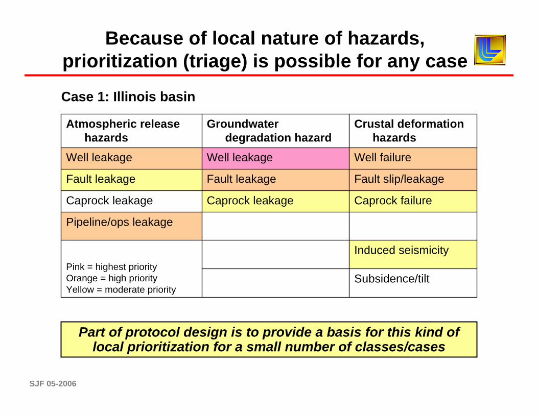
Case I: Central Illinois Basin
General• Many large point sources, some pure• Large-capacity targets (29-115 Gt in SF)• Solid geological knowledge
ICE components• Two main saline formations studied
(Mt. Simon, St. Peters)• O.K. injectivity, high capacity• Evidence of effectiveness
Central hazards• Deep wells• Unmapped faults• Groundwater risks
Risk coefficients – mostly decrease• Low population density• Faults don’t reach surface• Very few wells into deep targets• Effectively aseismic
Special thanks to the MGCS &Illinois State Geological Survey
SJF 05-2006
Because of local nature of hazards, prioritization (triage) is possible for any case
Well leakage and failure• Maximum rates, under what circumstances?• Maximum injection pressures?• Deep wells intersecting sensitive groundwater areas?
Pipeline leakage• How large to present a threat; where; how?
Induced seismicity/faults• Maximum sustainable reservoir pressures?• Faults posing greatest risks?
Due diligence could be met through aggressive site characterization, targeted monitoring, and simple mitigation strategies
Subsidence/tilt
Inducedseismicity
Pink = highest priorityOrange = high priorityYellow = moderate
priority
Pipeline/opsleakage
Caprock failureCaprock leakageCaprock leakage
Fault slip/ leakage
Fault leakageFault leakage
Well failureWell leakageWell leakage
Crustal Deformationhazards
Groundwaterdegradation hazards
Atmosphericrelease hazards
SJF 05-2006
Case II: TX-LA Gulf Coast
Special thanks to the SECARB & The Bureau of Economic Geology
General• Many large point sources, some pure• Very large capacity (177-710 Gt for SF)• World-class geological knowledge
ICE components• Many potential reservoirs and seals• High injectivity, high capacity• Evidence of geological effectiveness
Central hazards• V. high density of deep wells• Mapped faults• Groundwater risks
Risk coefficients – varies spatially• Low - high population density• Some faults reach the surface• Many wells into deep targets• Effectively aseismic, but mechanical risks
SJF 05-2006
An alternative prioritization could be proposed for other cases (e.g., Texas GOM)
Subsidence/tilt
Induced seismicity
Pink = highest priorityOrange = high priorityYellow = moderate priority
Pipeline/ops leakage
Caprock failureCaprock leakageCaprock leakage
Fault slip/leakageFault leakageFault leakage
Well failureWell leakageWell leakage
Crustal deformation hazards
Groundwater degradation hazard
Atmospheric release hazards
Prioritization uses expert knowledge and can be advised by science and experience
SJF 05-2006
Subsidence/tilt
Inducedseismicity
Pink = highest priorityOrange = high priorityYellow = moderate
priority
Pipeline/opsleakage
Caprock failureCaprock leakageCaprock leakage
Fault slip/ leakage
Fault leakageFault leakage
Well failureWell leakageWell leakage
Crustal Deformationhazards
Groundwaterdegradation hazards
Atmosphericrelease hazards
Atmospheric release• Pipeline leakage maxima?• Location of unmapped/abandoned wells?
Well leakage and failure• Maximum rates, under what circumstances?• Maximum injection pressures?• Deep wells intersecting sensitive groundwater areas?
Pipeline leakage• How large to present a threat; where; how?
Fault slip and leakage• Maximum sustainable reservoir pressures?• Faults posing greatest risks?
A protocol for the Gulf coast should focus on wells, wells, and wells
Due diligence could be met through aggressive site characterization, targeted monitoring, and simple mitigation strategies
SJF 05-2006
The monitoring suite design and integration should focus on the hazards
Well leakage and failure• Aeromagnetic surveys• Well-head sniffers/sensors• Overlying unit pressure sensors
Some approaches are obvious – others may have limited value in understanding hazards
Not so obvious
Deep arrays• Cross-well tomography• VSP
Surface arrays• LiDAR/FTIRS• Soil gas flux chambers• Atmospheric eddy towers
In all cases, real-time integration will provide clear understandings with the smallest M&V suite
SJF 05-2006
A two-phase technical program can help provide insight needed to develop CCS protocols
First, simulations should provide constraints on CCS operating conditions
Second, a field program must substantiate these constraints
The program should focus on EARTH & ATMOSPHERIC HAZARDS of greatest relevance and provide:
• If CO2 leaks, what’s the groundwater impact?• Will large earthquakes occur due to CO2 injection?• Can our pipeline be routed in a way to minimize risk?
Bounding analyses and simulations are necessary but not sufficient to create broad protocols
SJF 05-2006
Conclusions
Operational protocols will help CCS deployment• Help guide regulations, standards• Help gain public acceptance• Help operators make decisions
Hazards are the key• Provide decision-making framework• Flexible to local geology• Guide planning monitoring• First step in risk quantification
The map is not the territory
Alfred Korzbyski
SJF 05-2006
The E&A hazards and need for protocols leads to a few important questions
•What is the technical basis for developing a risk hierarchy? How can that basis be improved?
•If wells represent the greatest risk, how can that risk be quickly characterized, quantified, and managed?
•If geomechanics represent substantial risks, what are the minimal data necessary to properly characterize those risks
•What science is necessary to understand the potential risks to fresh groundwater?
•What is the least monitoring necessary to serve the needs of all stakeholders?
SJF 05-2006
The full list of E&A hazards suggests a need to rank, quantify, and respond to risk elements
Use of analogs• Industrial analogs (NG storage)• Natural analogs (HC systems, CO2 domes)
Simulation• Key features & processes• Must be accurate, but not unduly complex
Lab experimentation• Focus on most relevant problem• Experimental design is key
Scenario development• Max/min cases can be defined and tested
Risk assessment methodology• Requires integration of results• Some probabilistic methods as approp.
This suggests the need for PROTOCOLS to inform operators and regulators on what actions to take for preparing a site. Given the lack of empirical data, other approaches are needed.


![[05] Scheduling Algorithms - University of Cambridge · Intuition from FCFS leads us to shortest job first (SJF) ... For both SJF and SRTF require the next "burst length" for each](https://static.documents.pub/doc/80x56/5ad462507f8b9a6d708b88e2/05-scheduling-algorithms-university-of-cambridge-from-fcfs-leads-us-to-shortest.jpg)

