8
Page 1 of 7 Operational specification of Scanreco HANDY handheld transmitter
Page 1 of 7
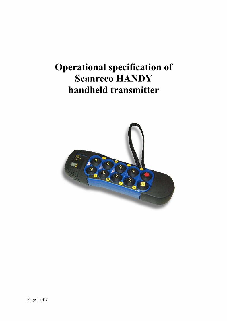
Operational specification of Scanreco HANDY
handheld transmitter

Page 2 of 7
1. Pushbuttons ....................................... ................................................... ............................. 3
1.1. Transmitter start up ............................................................................................................ 3
2. Mode description .................................. ................................................... .......................... 4
2.1. Operational mode ................................................................................................................. 4
2.2. Operational mode 2 .............................................................................................................. 4
2.3. Test mode .............................................................................................................................. 4
2.4. Assign mode .......................................................................................................................... 4
2.5. Calibrate mode ..................................................................................................................... 5
2.6. Information mode ................................................................................................................ 7
Page 3 of 7
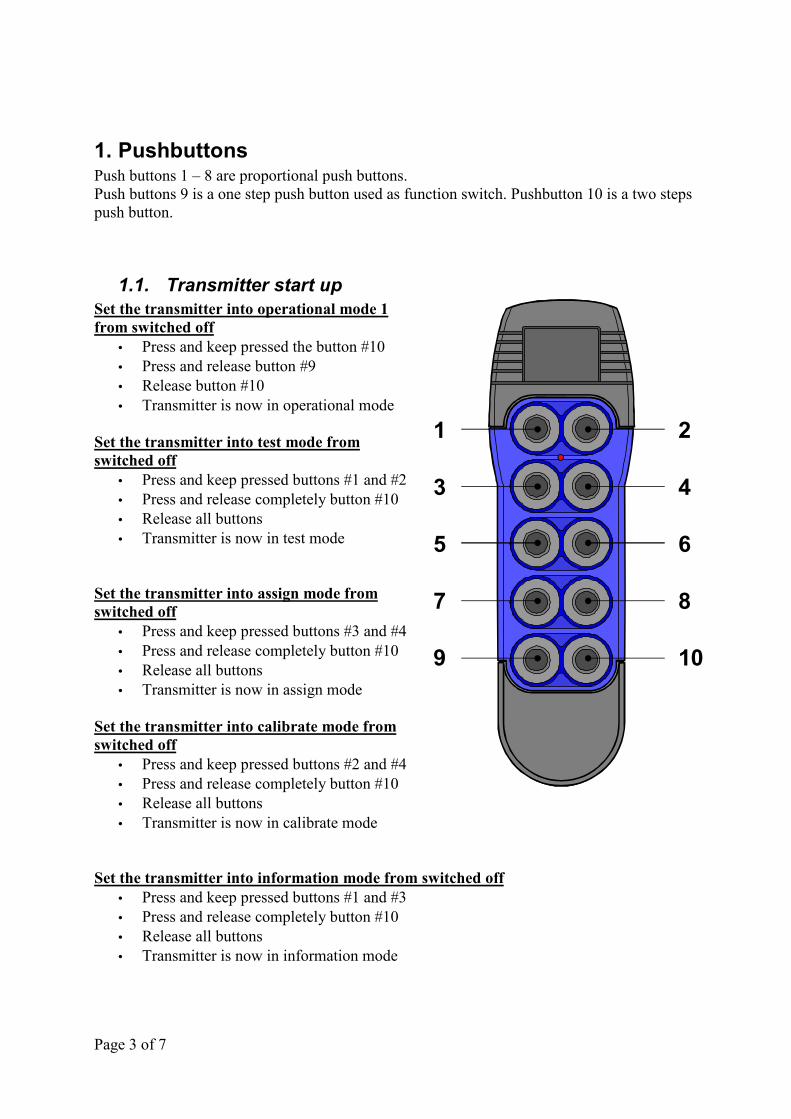
1. Pushbuttons Push buttons 1 – 8 are proportional push buttons. Push buttons 9 is a one step push button used as function switch. Pushbutton 10 is a two steps push button.
1.1. Transmitter start up Set the transmitter into operational mode 1 from switched off
• Press and keep pressed the button #10 • Press and release button #9 • Release button #10 • Transmitter is now in operational mode
Set the transmitter into test mode from switched off
• Press and keep pressed buttons #1 and #2 • Press and release completely button #10 • Release all buttons • Transmitter is now in test mode
Set the transmitter into assign mode from switched off
• Press and keep pressed buttons #3 and #4 • Press and release completely button #10 • Release all buttons • Transmitter is now in assign mode
Set the transmitter into calibrate mode from switched off
• Press and keep pressed buttons #2 and #4 • Press and release completely button #10 • Release all buttons • Transmitter is now in calibrate mode
Set the transmitter into information mode from switched off • Press and keep pressed buttons #1 and #3 • Press and release completely button #10 • Release all buttons • Transmitter is now in information mode
1
3
5
7
9
2
4
6
8
10

Page 4 of 7
2. Mode description
2.1. Operational mode • Push buttons 1 – 8 controls pre defined motions of the crane (mapping set in the
receiver) • Push button 9 changes into operational mode 2 • Every time push button 9 is toggled, the display shows the operative mode “1” or "2"
for 8 seconds. • Push button 10 (any step) will switch the transmitter completely off
2.2. Operational mode 2 To work in mode 2 push, and keep down, push-button no.9. Releasing push-button no.9 will bring into operational mode 1.
• Push buttons 1 – 4 controls pre defined motions of the crane and 5 – 8 controls pre defined on off signals on the crane (mapping set in the receiver)
• Push button 9 changes into operational mode 2 • Every time push button 9 is toggled, the display shows the operative mode “1” or "2"
for 8 seconds. • Push button 10 (any step) will switch the transmitter completely off
2.3. Test mode • All segments in the 7-segment display is lit • All diode indicators are lit • The on board buzzer is used to indicate function of all push buttons. • The number in the 7-segment display cycle through 0 to 9 while buzzer sounds
proportionally to the pressure on each button (push button 1 to 8). • Push button 9 will only beep once each toggle. • Push button 10 (both steps) will switch the transmitter completely off • No connection to receiver is possible
2.4. Assign mode • The transmitter will transmit an assign command to a near by receiver (distance ~15
cm), the transmission will continue until the transmitter timeout is reached (2s - 5s - 10s - infinite), during this time the receiver must be rebooted with the "pairing plug" connected.
• Push button 10 (any step) will switch the transmitter completely off

Page 5 of 7
2.5. Calibrate mode • Push button 9 is used to switch between the various calibration steps, a single press
will increase the calibration step by one • Push button 10 (any step) will switch the transmitter completely off, this will also
store any parameters changed in the transmitter
Step 01 – setting of transmitter timeout - “1” is displayed in the 7-segment - Push buttons 1 sets timeout times to 2 minutes - Push buttons 2 sets timeout times to 5 minutes - Push buttons 3 sets timeout times to 10 minutes - Push buttons 4 sets timeout times to � (infinite)
Step 02 – setting of frequency locking - Push button 1 edit the first digit of the two digit frequency number - Use button 3 and 4 to brows to the right digit - Push button 2 to start edit the second digit of the two digit frequency number - Use button 3 and 4 to brows to the right digit - Use button 2 to stor the selected frequency number (00 indicates no frequency lock,
for EU countries the selection must vary between 1 and 68)
Step 03 – setting of transmitter type - “3” is displayed in the 7-segment - Push button 1 – 8 represent transmitter type 1 – 8 (must be set to "1").
Step 4 – setting of A / B start speed crane drive 1- Push buttons 1 and 2 are used to activate the crane motion on which to perform the
speed change - Push buttons 3 and 4 are used as – and + to decrease or increase the start speed on the
selected direction Step 5 – setting of A / B stop speed crane drive 1 - Push buttons 1 and 2 are used to activate the crane motion on which to perform the
speed change - Push buttons 3 and 4 are used as – and + to decrease or increase the stop speed on the
selected direction
Step 6 – setting of A / B start speed crane drive 2- Push buttons 1 and 2 are used to activate the crane motion on which to perform the
speed change - Push buttons 3 and 4 are used as – and + to decrease or increase the start speed on the
selected direction
Step 7 – setting of A / B stop speed crane drive 2 - Push buttons 1 and 2 are used to activate the crane motion on which to perform the
speed change - Push buttons 3 and 4 are used as – and + to decrease or increase the stop speed on the
selected direction

Page 6 of 7
Step 8 – setting of A / B start speed crane drive 3- Push buttons 1 and 2 are used to activate the crane motion on which to perform the
speed change - Push buttons 3 and 4 are used as – and + to decrease or increase the start speed on the
selected direction Step 9 – setting of A / B stop speed crane drive 3 - Push buttons 1 and 2 are used to activate the crane motion on which to perform the
speed change - Push buttons 3 and 4 are used as – and + to decrease or increase the stop speed on the
selected direction Step 10 – setting of A / B start speed crane drive 4 - Push buttons 1 and 2 are used to activate the crane motion on which to perform the
speed change - Push buttons 3 and 4 are used as – and + to decrease or increase the start speed on the
selected direction Step 11 – setting of A / B stop speed crane drive 4- Push buttons 1 and 2 are used to activate the crane motion on which to perform the
speed change - Push buttons 3 and 4 are used as – and + to decrease or increase the stop speed on the
selected direction Step 12 – setting of A / B start speed crane drive 5 - Push buttons 1 and 2 are used to activate the crane motion on which to perform the
speed change - Push buttons 3 and 4 are used as – and + to decrease or increase the start speed on the
selected direction Step 13 – setting of A / B stop speed crane drive 5- Push buttons 1 and 2 are used to activate the crane motion on which to perform the
speed change - Push buttons 3 and 4 are used as – and + to decrease or increase the stop speed on the
selected direction Step 14 – setting of A / B start speed crane drive 6 - Push buttons 1 and 2 are used to activate the crane motion on which to perform the
speed change - Push buttons 3 and 4 are used as – and + to decrease or increase the start speed on the
selected direction Step 15 – setting of A / B stop speed crane drive 6- Push buttons 1 and 2 are used to activate the crane motion on which to perform the
speed change - Push buttons 3 and 4 are used as – and + to decrease or increase the stop speed on the
selected direction
Step 16 – 23 setting of on/off buttons - Push buttons 1 and 2 are used to display the current status of the on/off (L = latched or
o = non-latched – shown only in the display inside the receiver). - Push buttons 3 or 4 are used to toggle between latched or non-latched status
"Latched" mode must be enabled in the receiver, to work.
Page 7 of 7
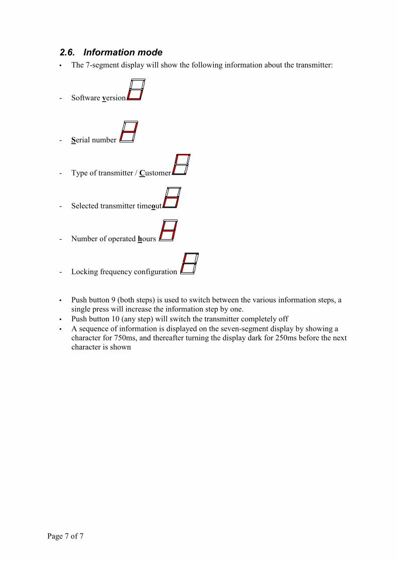
2.6. Information mode • The 7-segment display will show the following information about the transmitter:
- Software version
- Serial number
- Type of transmitter / Customer
- Selected transmitter timeout
- Number of operated hours
- Locking frequency configuration
• Push button 9 (both steps) is used to switch between the various information steps, a single press will increase the information step by one.
• Push button 10 (any step) will switch the transmitter completely off • A sequence of information is displayed on the seven-segment display by showing a
character for 750ms, and thereafter turning the display dark for 250ms before the next character is shown
Pairing procedure for HANDY radio remote control
1) Get started with the receiver and the transmitter both off.
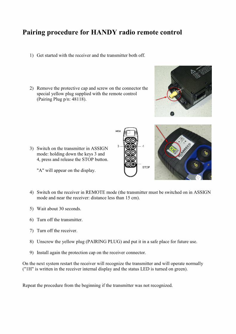
2) Remove the protective cap and screw on the connector the special yellow plug supplied with the remote control (Pairing Plug p/n: 48118).
3) Switch on the transmitter in ASSIGN mode: holding down the keys 3 and 4, press and release the STOP button.
"A" will appear on the display.
4) Switch on the receiver in REMOTE mode (the transmitter must be switched on in ASSIGN mode and near the receiver: distance less than 15 cm).
5) Wait about 30 seconds.
6) Turn off the transmitter.
7) Turn off the receiver.
8) Unscrew the yellow plug (PAIRING PLUG) and put it in a safe place for future use.
9) Install again the protection cap on the receiver connector.
On the next system restart the receiver will recognize the transmitter and will operate normally ("1H" is written in the receiver internal display and the status LED is turned on green).
Repeat the procedure from the beginning if the transmitter was not recognized.


