94
OPERATOR MANUAL Reliance ® 400 Laboratory Glassware Washer Reliance ® 500 Laboratory Glassware Washer (2007-06-27) P122994-513
OPERATOR MANUAL
Reliance® 400 Laboratory Glassware WasherReliance® 500 Laboratory Glassware Washer
(2007-06-27) P122994-513

A WORD FROM STERIS CORPORATION
This manual contains important information on the proper use androutine maintenance of the Reliance® 400 Laboratory GlasswareWasher and the Reliance® 500 Laboratory Glassware Washer. Allpersonnel involved in the use and maintenance of this equip-ment must carefully review and comply with the Safety Precau-tions and instructions contained in this manual. Theseinstructions are important to protect the health and safety of person-nel operating this glassware washer and should be retained in a con-veniently accessible area for quick reference. This equipment isspecifically designed only for the uses outlined in this manual.
Complete instructions for uncrating and connecting utilities, as wellas the equipment drawing, have been provided. If they are missing,contact STERIS for replacement copies, providing the serial numberand model of the glassware washer.
Advisory IMPORTANT: A listing of the Safety Precautions to be observedwhen operating and servicing this glassware washer can be found inSECTION 1 of this manual. Do not operate the equipment until youhave become familiar with this information.
Any alteration of this equipment not authorized or performed bySTERIS will void the warranty. Alteration of equipment which couldadversely affect its operation and efficacy may violate national, stateand local regulations.
To help ensure operators are adequately trained in the safe use ofthis equipment, STERIS recommends:
- all personnel who operate or maintain the equipment aretrained in its operation and in its safe use;
- personnel working with toxic chemicals and vapors (if appli-cable) have comprehensive instructions in the glasswarewasher process, relevant health hazards and methods todetect and avoid exposure to the escape of toxic materials;
- there is regular training of all personnel concerned withoperation and maintenance of the equipment; attendancerecords are maintained; and evidence of understanding isdemonstrated.
- current Material Safety Data sheets (MSDS) should beavailable to all users in the department. For current MSDSsheets, contact STERIS.
©2007, STERIS Corporation. All rights reserved. Printed in Canada.
iIntroduction Operator Manual 122994-513
Indications For Use Reliance 400 and Reliance 500 Laboratory Glassware Washersare intended for use in cleaning of laboratory glassware, plas-ticware and metal goods used in research, production supportand quality control laboratories. This washer is specificallydesigned to only process goods as outlined in this manual. If thereis any doubt about a specific material or product, contact productmanufacturer for recommended washing technique.
Service Information A thorough preventive maintenance program is essential to helpensure safe and proper equipment operation. This manual containsmaintenance schedules and procedures which should be followedfor satisfactory equipment performance.
Customers are encouraged to contact STERIS concerning our com-prehensive annual maintenance program. Under the terms of theprogram, preventive maintenance, adjustments and replacement ofworn parts are performed on a scheduled basis to help ensureequipment performance at peak capability and to help avoiduntimely and costly interruptions. STERIS maintains a global staff ofwell-equipped, qualified service technicians to provide this service,as well as expert repair services. Please contact STERIS for details.
STERIS provides a complete line of accessories for use with thisequipment. A STERIS representative will gladly review these withyou.
NOTE: Certain options may not be available in your area. ContactSTERIS for product availability and ordering information.
ii122994-513 Operator Manual Introduction

Certification Reliance 400 Laboratory Glassware Washer and Reliance 500Laboratory Glassware Washer meet the applicable requirements ofthe following standards, as certified by UL:
Underwriters Laboratories Standard (UL):
UL 61010-1, Second Edition.
Canadian Standards Association (CSA):
CAN/CSA-C22.2 No. 61010-1, Second Edition.
Governing directive for the affixing of the CE mark:
Machinery Directive 98/37/EC.
Conformity to other applicable directives:
Electromagnetic Compatibility Directive (89/336/EEC) amended byDirective 91/263/EEC, Directive 92/31/EEC and Directive 93/68/EEC.
Low Voltage Directive 73/23/EEC amended by Directive 93/68/EEC.
Standards applied to demonstrate conformity to the directives:
International Standard IEC 61010-1, Second Edition.
International Standard IEC 61326-1.
Corporation STERIS Canada
Québec, Qc, CANADA
ISO 13485 ISO 9001 Certified Facility
The base language of this document isENGLISH. Any translations must bemade from the base language document.
STERIS Limited
STERIS House
Jays Close
Viables
Basingstoke
Hampshire
RG22 4AX
United Kingdom
Sales and Service:
STERIS Corporation
5960 Heisley Road
Mentor, Ohio 44060
440-354-2600 • 800-444-9009
www.steris.com
iiiIntroduction Operator Manual 122994-513

TABLE OF CONTENTS
A WORD FROM STERIS CORPORATION..................................................................iAdvisory............................................................................................................................................................ i
Indications For Use...........................................................................................................................................ii
Service Information...........................................................................................................................................ii
Certification......................................................................................................................................................iii
1 SAFETY PRECAUTIONS ......................................................................................1-1
2 INSTALLATION VERIFICATION...........................................................................2-12.1 Technical Specifications.........................................................................................................................2-1
2.1.1 Voltage, Amperage and Power Consumption.................................................................................2-1
2.1.2 Noise Level......................................................................................................................................2-2
2.1.3 Permissible Environmental Conditions............................................................................................2-2
2.1.4 Seismic Anchorage System ............................................................................................................2-2
2.2 Installation Checklist...............................................................................................................................2-2
2.3 Detergents and Chemical Additives Specifications ...............................................................................2-4
3 COMPONENT IDENTIFICATION...........................................................................3-13.1 Before Operating Glassware Washer.....................................................................................................3-1
3.2 Control Location .....................................................................................................................................3-2
3.2.1 Power Switch...................................................................................................................................3-2
3.2.2 POWER-OFF/STANDBY Switch.......................................................................................................3-2
3.2.3 Printer ..............................................................................................................................................3-2
3.3 Load Side Control Panel.........................................................................................................................3-4
3.3.1 Display Screen ................................................................................................................................3-4
3.3.2 Touch Pads .....................................................................................................................................3-4
3.4 Unload Side Control Panel .....................................................................................................................3-5
4 OPERATING INSTRUCTIONS ..............................................................................4-14.1 Before Operating Equipment..................................................................................................................4-1
4.2 Priming Procedure..................................................................................................................................4-2
4.3 Accessories ............................................................................................................................................4-3
4.4 Loading Glassware Washer ...................................................................................................................4-6
4.4.1 Universal Shelving System (Optional).............................................................................................4-6
4.4.2 Universal Shelving System (Optional) – Reliance 400 ...................................................................4-6
4.4.3 Universal Shelving System (Optional) – Reliance 500 ...................................................................4-8
Continued...
Section Number Description Page
v122994-513 Operator Manual Table of Contents
TABLE OF CONTENTS (Cont’d)
4 OPERATING INSTRUCTIONS (Cont’d)4.5 Typical Cycle Operation .........................................................................................................................4-9
4.6 Extend Cycle Treatment .......................................................................................................................4-13
4.7 Acknowledge Alarm Condition .............................................................................................................4-14
4.8 Stop Cycle Operation ...........................................................................................................................4-15
4.9 Abort Cycle Operation..........................................................................................................................4-16
4.10 Shutdown............................................................................................................................................4-16
4.11 Power Door Operation........................................................................................................................4-18
4.11.1 Door Obstruction.........................................................................................................................4-18
4.11.2 Power Door Operation During a Power Failure ...........................................................................4-19
5 CYCLE AND CONTROL VALUE PROGRAMMING.................................................5-15.1 General ...................................................................................................................................................5-1
5.2 Change Values Mode.............................................................................................................................5-3
5.3 Treatment Sequence and Display Screens............................................................................................5-4
5.4 Modifying Factory-Set Cycles.................................................................................................................5-5
5.5 Adding Cycle Treatments.......................................................................................................................5-9
5.6 Creating Custom Cycles.......................................................................................................................5-13
5.7 Removing Treatments From Cycles .....................................................................................................5-16
5.8 Changing Miscellaneous Values ..........................................................................................................5-20
5.9 Select Injection Time Rate ....................................................................................................................5-25
5.9.1 General..........................................................................................................................................5-25
5.9.2 Verifying Chemical Concentration.................................................................................................5-29
5.10 Programming Values With Access Code Enabled .............................................................................5-30
5.11 Review Cycle Values ..........................................................................................................................5-31
6 ROUTINE MAINTENANCE....................................................................................6-16.1 General ...................................................................................................................................................6-1
6.2 Preventive Maintenance .........................................................................................................................6-2
6.3 Daily Cleaning ........................................................................................................................................6-4
6.4 Weekly Cleaning.....................................................................................................................................6-4
6.5 Monthly Cleaning....................................................................................................................................6-5
6.5.1 Remove Hard Water Deposits.........................................................................................................6-5
6.5.2 Clean Building Supply-Line Strainers .............................................................................................6-6
Continued...
Section Number Description Page
viTable of Contents Operator Manual 122994-513
TABLE OF CONTENTS (Cont’d)
6 ROUTINE MAINTENANCE (Cont’d)6.6 Chemical Container Replacement..........................................................................................................6-6
6.7 Inspect and Lubricate Peristaltic Injection Pump Squeeze Tubes.........................................................6-7
6.8 Verify Power Doors .................................................................................................................................6-8
6.9 Changing Printer Paper Roll ...................................................................................................................6-8
6.10 Storing Thermal Paper........................................................................................................................6-10
7 TROUBLESHOOTING.......................................................................................... 7-1
Section Number Description Page
vii122994-513 Operator Manual Table of Contents

LIST OF ILLUSTRATIONS
Section 3: Component Identification
3-1 Component Identification..................................................................................................................... 3-1
3-2 Printer and Front Control Panel............................................................................................................ 3-3
Section 4: Operating Instructions
4-1 Chemical Container ............................................................................................................................. 4-1
4-2 Bottom Rotary Spray Headers ............................................................................................................. 4-4
4-3 Glassware Support .............................................................................................................................. 4-5
4-4 Pipette Header..................................................................................................................................... 4-5
4-5 Universal Shelving System (Reliance 500 Shown) .............................................................................. 4-7
4-6 Universal Shelving System – Reliance 400......................................................................................... 4-7
4-7 Universal Shelving System – Reliance 500......................................................................................... 4-7
4-8 Printout With Extended Cycle Treatment ........................................................................................... 4-13
4-9 Power Door Operation During a Power Failure.................................................................................. 4-19
4-10 Safety Door Stop (Reliance 400 Only) ............................................................................................... 4-20
Section 5: Cycle and Control Value Programming
5-1 Change Values Mode Functions.......................................................................................................... 5-3
5-2 Change Values Mode – Program Tree ................................................................................................ 5-3
5-3 Change Values Mode – Modifying Cycle Treatments ......................................................................... 5-6
5-4 Change Values Mode – Adding Cycle Treatments ........................................................................... 5-10
5-5 Change Values Mode – Creating Custom Cycles ............................................................................. 5-14
5-6 Change Values Mode – Removing Treatments From Cycles ............................................................ 5-17
5-7 Change Values Mode – Changing Miscellaneous Values................................................................. 5-21
5-8 Change Values Mode – Select Injection Time Rate........................................................................... 5-26
5-9 Sample Port ....................................................................................................................................... 5-29
5-10 Change Values Mode – Programming With Access Code Enabled ................................................. 5-30
Section 6: Routine Maintenance
6-1 Changing Printer Paper Roll ................................................................................................................ 6-9
Figure Description Page
ix122994-513 Operator Manual List of Illustrations
1SAFETY PRECAUTIONS
The following Safety Precautions must be observed when operating or servicing this Reliance® 400 LaboratoryGlassware Washer or this Reliance® 500 Laboratory Glassware Washer. WARNING indicates the potential for per-sonal injury and CAUTION indicates the potential for damage to equipment. For emphasis, certain Safety Precau-tions are repeated throughout the manual. It is important to review ALL Safety Precautions before operating orservicing the glassware washer.
WARNING – PERSONAL INJURY AND/OR EQUIPMENT DAMAGE HAZARD:
WARNING – PERSONAL INJURY HAZARD:
WARNING – ELECTRIC SHOCK AND/OR BURN HAZARD:
Always load baskets on appropriate loading cart or surface.
If an obstruction is present in wash chamber door, door safety sensor will detect obstruction and doorwill automatically stop closing. Wait until door is fully open and water flow has stopped before removingobstruction.
If an obstruction is present in wash chamber door and door is unable to raise, DO NOT attempt toremove obstruction from under door. Door cables may have loosen which could cause door to close athigh speed when obstruction is removed. Call a qualified service technician to safely remove anobstruction.
Regularly scheduled preventive maintenance is required for safe and reliable operation of this equip-ment. Contact STERIS to schedule preventive maintenance.
Repairs and adjustments to this equipment must be made only by STERIS or STERIS-trained servicepersonnel. Repairs and adjustments performed by unqualified personnel or installation of unauthorizedparts could cause personal injury, result in improper equipment performance, void the warranty or resultin costly damage. Contact STERIS regarding service options.
Chamber door is heavy. Lifting it manually may require two people.
In case of power loss, power door(s) lowers slowly by gravity. Keep hands and items out of door area toavoid personal injury.
Fasteners and star washers are used to ensure protective bonding continuity. Always reinstall any starwasher which may have been removed during installation or servicing.
STERIS strongly recommends service be performed only by STERIS or STERIS-trained service per-sonnel. Service personnel must disconnect all utilities to unit before servicing. No one should serviceunit unless all utilities have been properly locked out. Always follow local electrical codes and safety-related work practices.
1-1Safety Precautions Operator Manual 122994-513
WARNING – POSSIBLE FIRE HAZARD:
WARNING – CHEMICAL BURN AND/OR EYE INJURY HAZARD:
WARNING – BURN HAZARD:
WARNING – SLIPPING HAZARD:
CAUTION – POSSIBLE EQUIPMENT DAMAGE:
When glassware washer is installed on a combustible floor, floor must be covered with a metal sheetextending to the outer edges of glassware washer.
Detergents are caustic and can cause adverse effects to exposed tissues. Do not get in eyes, on skin orattempt to swallow. Read and follow the precautions and instructions on the detergent label and in theMaterial Safety Data Sheet (MSDS) prior to handling the detergent, refilling the detergent container orservicing the detergent injection pump and lines. Wear appropriate Personal Protective Equipment(PPE) whenever handling the detergent or servicing the detergent injection pump and lines.
Wear appropriate Personal Protective Equipment (PPE) when using a descaling product. Avoid contactwith the eyes or skin. If a descaling product spills or splashes on you, flush the affected area with waterfor 15 minutes. If swallowed, DO NOT induce vomiting. Administer an alkali with plenty of water. Seekmedical attention immediately.
After pressing STOP/RESET touch pad, wait until water flow stops before slowly opening door. Hotwater/steam may be sprayed through door opening if door is opened too soon.
Allow piping to cool before inspecting and/or cleaning supply-line strainers.
Except for an emergency, do not open door when cycle is in progress. In an emergency, first stop cycleby pressing STOP/RESET touch pad and wait for water flow to stop. Wear appropriate Personal Protec-tive Equipment (PPE) whenever reaching into chamber.
Wear appropriate Personal Protective Equipment (PPE) and open door slowly if it is necessary to openduring a cycle. Hot water/steam may be sprayed through door opening when verifying automatic stopwhile washer is operating.
To prevent slips, keep floors dry. Promptly clean up any spills or drippage. For spills or drippage ofdetergents or other chemicals, follow safety precautions and handling procedures set forth on detergentor chemical label and/or Material Safety Data Sheet (MSDS).
Always position each manifold and/or bottom rotary spray over a manifold connector before operatingunit. If manifolds and/or bottom rotary sprays are not positioned correctly, damage will result and unitwill be unable to effectively wash load.
Always position each accessory header over a manifold connector before operating unit. If accessoryheaders are not positioned correctly, damage may result and unit will be unable to effectively wash load.
1-2122994-513 Operator Manual Safety Precautions

CAUTION – POSSIBLE EQUIPMENT DAMAGE (Cont’d):
1 Vaseline is a trademark of Cheseborough Pond's Incorporated.
Always select a cycle appropriate for the items being processed. Failure to do so may result in productdamage.
Always use a silicone lubricant to lubricate squeeze tubes. Petroleum-based lubricants, such as Vase-line®1 or grease, will cause squeeze tubes to melt.
Once chamber door has been lowered, ensure cable is correctly aligned and routed on all six cable pul-leys.
Use nonabrasive cleaners when cleaning unit. Follow directions on containers and rub in a back-and-forth motion (in same direction as surface grain). Abrasive cleaners will damage stainless steel.Cleaners rubbed in a circular motion or applied with a wire brush or steel wool on door and chamberassemblies can be harmful to stainless steel. Do not use these cleaners on painted surfaces.
When choosing a detergent, select one with a low-chloride content. Detergents with a high-chloridecontent must not be used, as such detergents may harm stainless steel.
1-3Safety Precautions Operator Manual 122994-513

Table 1-1 contains symbols which may be on your Reliance 400 or Reliance 500 Laboratory Glassware Washerscomponents:
Table 1-2 contains symbols which may be on the identification nameplate of your Reliance 400 or Reliance 500Laboratory Glassware Washers:
Table 1-1. Definition of Symbols on Glassware Washer
Symbol Definition
Protective Earth (Ground).
Warning! Risk of Electrical Shock.
Attention. Refer to Manual For Further Instructions.
ON (For Part of Equipment).
OFF (For Part of Equipment).
Transfer of Heat, Hot Surface.
Table 1-2. Definition of Symbols on Identification Nameplate
Symbol Definition
MODEL Model of Unit.
S/N Serial Number of Unit.
kVA Power Rating of Unit.
V_~ Volt, Number of Phase (3 or 1), Alternating Current.
A Amperage Rating of Unit.
Year Year of Manufacture of Unit.
Hz Hertz – Frequency of Unit.
WIRE Number of Wires in Electrical Cable Excluding Protective Ground Wire.
1-4122994-513 Operator Manual Safety Precautions
2INSTALLATION VERIFICATION
2.1 TechnicalSpecifications
These specifications are intended to describe the technical infor-mation given on the identification nameplate of the Reliance® 400Laboratory Glassware Washer or the Reliance® 500 LaboratoryGlassware Washer and to state other relevant information. Verifyequipment drawing (122992-953 for Reliance 400 or 122993-554 forReliance 500) or identification nameplate (located in the middle sec-tion of lower service access panel compartment, on load side or onright bottom corner load side) for proper voltage and amperage.
2.1.1 Voltage, Amperage andPower Consumption
Both Laboratory Glassware Washers operate either on:
• 120/208 V, 60 Hz, three-phase, four-wire, steam-heated;
• 480 V, 60 Hz, three-phase, three-wire, steam-heated;
• 380/400/415 V, 50 Hz, three-phase, three-wires, steam-heated;
• 600 V, 60 Hz, three-phase, three-wire, steam-heated;
• 480 V, 60 Hz, three-phase, three-wire, electric-heated;
• 380/400/415 V, 50 Hz, three-phase, three-wire, electric-heated;
• 600 V, 60 Hz, three-phase, three-wire, electric-heated.
• Maximum currents and power consumptions are indicated onidentification nameplate (refer to Figure 3-1).
• A protective ground conductor is required (Class 1 Equipment).
• Main supply voltage fluctuation not exceeding ± 10 percent ofnominal voltage.
• Installation Category: Overvoltage Category II.
• Overvoltage attenuation must be provided. Equipment must beconnected in a way to reduce transient voltage at electrical mainsupply. Overvoltage attenuation can be achieved by:
a. connecting equipment main supply to a distribution systemwith multiple branch circuits;
b. connecting equipment main supply through an isolatingtransformer (380/400/415 V [input, output], three-phase,30 kVA; 208 V [input, output], three-phase, 15 KVA; 480 V[input, output], three-phase, 30 kVA; or 600 V [input,output], three-phase, 30 kVA).
IMPORTANT: Customer is responsible for compliance withapplicable codes and regulations.
Refer to Uncrating/Installation Instructions (P122996-649) for properconnection.
2-1Installation Verification Operator Manual 122994-513
2.1.2 Noise Level Equivalent Sound Pressure Level at work station, measured 36"(1.0 m) away from equipment and at 63" (1.6 m) from ground:67.6 dB (A). Results determined according to ISO-3746:1979Standard: Acoustics Determination of Sound Power Levels of NoiseSources Survey Method).
2.1.3 PermissibleEnvironmental Conditions
This glassware washer is designed to give optimal results under thefollowing conditions:
- Indoor use only;
- Altitude of operation up to 6,562 ft (2,000 m);
- Temperature of 41 to 104°F (5 to 40°C);
- Maximum relative humidity is 80% for temperatures up to88°F (31°C), decreasing linearly to 50% relative humidity at104°F (40°C);
- Pollution Degree 2.
Pollution degree 2: Equipment must be installed in an environmentwhere normally only non-conductive pollution occurs but whereoccasional, temporary conductivity caused by condensation canbe expected (as determined according to International StandardEN/IEC 61010-1, Second Edition).
2.1.4 Seismic AnchorageSystem
A seismic anchorage system (based on California requirements) isavailable for high-risk seismic zones.
2.2 InstallationChecklist
After installing the glassware washer according to the Uncrating/Installation Instructions (P122996-649), complete the followingchecklist to help ensure complete and correct installation, or contactSTERIS to schedule a service technician to test your installation anddemonstrate proper equipment operation.
❑ Shutoff valves (not provided by STERIS) capable of being lockedin OFF position only for maintenance purposes, installed onsteam, air and water lines, and in compliance with local occupa-tional health and safety regulations, as well as electric andplumbing codes for any special requirements that may pertain toinstallation of this glassware washer.
❑ Disconnect switches (not provided by STERIS) capable of beinglocked in OFF position only, installed in electrical supply linesnear the glassware washer and in compliance with local occupa-tional health and safety regulations, as well as electric andplumbing codes for any special requirements that may pertain toinstallation of this glassware washer.
NOTE: If unit is installed next to other equipment, shutoff valvesand disconnect switches should be located so service can beshut off to one piece of equipment at a time.
2-2122994-513 Operator Manual Installation Verification
❑ Glassware washer is positioned, as shown on equipment draw-ing (122992-953 for Reliance 400 or 122993-554 for Reliance500), with required clearance space and in relation to buildingsupply lines.
❑ Glassware washer is level. Use leveling legs, if necessary.
❑ If glassware washer is equipped with cold water pre-wash, draindischarge cooldown or non-vented vapor condenser option,building cold water line supplies water to glassware washer asspecified on equipment drawing.
❑ Building hot water line supplies water to glassware washer asspecified on equipment drawing.
❑ If glassware washer is steam-heated, building steam line pro-vides steam to glassware washer as specified on equipmentdrawing.
❑ If glassware washer is steam-heated, building condensate returnline is connected to glassware washer as specified on equip-ment drawing.
❑ Pure water line supplies water to glassware washer as specifiedon equipment drawing.
❑ Building air line supplies air to glassware washer as specified onequipment drawing.
❑ Building waste line is connected to glassware washer as speci-fied on equipment drawing.
❑ If vented glassware washer, building ventilation system is con-nected to glassware washer as specified on equipment drawing.
❑ Electrical supply for glassware washer is as specified on equip-ment drawing.
❑ Pressure for air, water and steam (if option applies) supplies iswithin range specified on equipment drawing.
❑ Chemical injection pumps are connected to proper chemicalinjection lines and each chemical suction tube and float areplaced in proper container.
❑ Chemical squeeze tubes have been lubricated.
❑ Floor underneath glassware washer has a noncombustible andnonslip surface or is covered with a metal sheet extending to theouter edges of the glassware washer.
❑ Walls surrounding glassware washer have a noncombustiblesurface.
IMPORTANT: After a few weeks of operation, inspect unit forleaks. Retighten all clamps and connections.
WARNING – POSSIBLE FIREHAZARD: When glasswarewasher is installed on a com-bustible floor, floor must becovered with a metal sheetextending to the outer edgesof glassware washer.
2-3Installation Verification Operator Manual 122994-513
2.3 Detergents andChemical Additives
Specifications
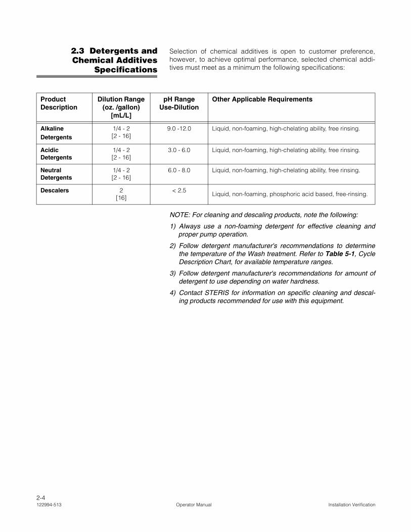
Selection of chemical additives is open to customer preference,however, to achieve optimal performance, selected chemical addi-tives must meet as a minimum the following specifications:
NOTE: For cleaning and descaling products, note the following:
1) Always use a non-foaming detergent for effective cleaning andproper pump operation.
2) Follow detergent manufacturer's recommendations to determinethe temperature of the Wash treatment. Refer to Table 5-1, CycleDescription Chart, for available temperature ranges.
3) Follow detergent manufacturer's recommendations for amount ofdetergent to use depending on water hardness.
4) Contact STERIS for information on specific cleaning and descal-ing products recommended for use with this equipment.
ProductDescription
Dilution Range (oz. /gallon)
[mL/L]
pH Range Use-Dilution
Other Applicable Requirements
Alkaline Detergents
1/4 - 2[2 - 16]
9.0 -12.0 Liquid, non-foaming, high-chelating ability, free rinsing.
Acidic Detergents
1/4 - 2[2 - 16]
3.0 - 6.0 Liquid, non-foaming, high-chelating ability, free rinsing.
Neutral Detergents
1/4 - 2[2 - 16]
6.0 - 8.0 Liquid, non-foaming, high-chelating ability, free rinsing.
Descalers 2[16]
< 2.5Liquid, non-foaming, phosphoric acid based, free-rinsing.
2-4122994-513 Operator Manual Installation Verification

To achieve maximum cleaning efficiency, select appropriate chemi-cal cleaner to soil type being processed. STERIS recommends thefollowing products:
• Glass-Klenz® Glassware Detergent is a blend of selectedcleaning and water conditioning agents for the cleaning oflaboratory glassware and glass components in pharmaceuti-cal and cosmetic manufacturing facilities and animal biotechresearch areas. Its effective detergent system operates on awide range of organic and inorganic soils, while water condi-tioning agents virtually eliminate spots in even problem waterareas.
• CIP 100® Alkaline Process and Research Cleaner is aliquid, alkaline detergent system specially formulated tomeet the unique cleaning demands found in pharmaceuti-cal, cosmetic, medical device and food and beverageindustries. It effectively removes a wide range of processresidues, from fermentation by-products to silicone-basedemulsions and lubricants.
• CIP 200® Acid-Based Process and Research Cleaner is aliquid, acidic detergent system specially formulated to meetthe unique cleaning demands found in pharmaceutical, cos-metic, medical device and food and beverage industries. Iteffectively removes a wide range of process residues, frominorganic salts to particulate carbon.
• CIP 220® Acid-Based Process and Research Cleaner is aliquid, hydroacetic acid-based detergent system speciallyformulated to meet the unique cleaning demands found inpharmaceutical, cosmetic, medical device and food andbeverage industries. Phosphate-free, it effectively removes awide range of process residues, from inorganic salts to par-ticulate carbon.
NOTE: Certain products may not be available in your area.Contact STERIS for product availability and orderinginformation.
IMPORTANT: STERIS does not promote, recommend orendorse the use of any other type of chemical additives in theprocessing of articles in this washer, such as drying agents,strong alkaline detergents (pH>12), alcohol rinses and liquidgermicides including hypochloric acid (bleach).
2-5Installation Verification Operator Manual 122994-513

3COMPONENT IDENTIFICATION
3.1 Before OperatingGlassware Washer
The Reliance® 400 Laboratory Glassware Washer and Reliance® 500Laboratory Glassware Washer are equipped with a fully-programma-ble microprocessor control system capable of storing up to 10 cyclesfor processing a wide variety of loads. Control system monitors andautomatically controls all cycle operations and functions.
Before operating either glassware washer, it is important to becomefamiliar with the locations and functions of all major components andcontrols (see Figures 3-1 and 3-2).
IMPORTANT: A listing of the Safety Precautions to be observed when operating and servicing this glass-ware washer can be found in SECTION 1 of this manual. Do not operate the equipment until you havebecome familiar with this information.
Reliance 400 Laboratory Glassware Washer
Lower Service Access Panel
Identification Nameplate
Control Panel
Printer
Upper Service Access Panel (Chemical Pump Access)
Wash Chamber
Door
Reliance 500 Laboratory Glassware Washer
Lower Service Access Panel
Identification Nameplate
Chemical Storage
Compartment
Control Panel
Printer
Upper Service Access Panel
Wash Chamber
Door
Side Service Access Panel
Figure 3-1. Component Identification
3-1Component Identification Operator Manual 122994-513
3.2 Control Location
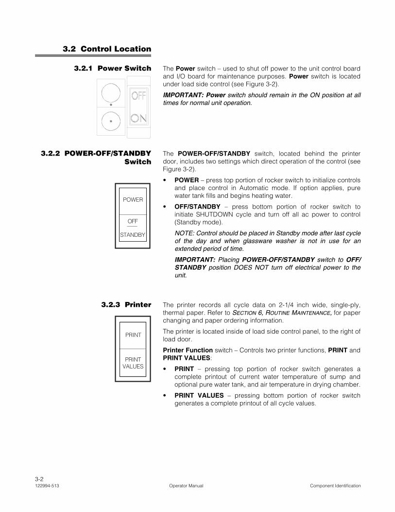
3.2.1 Power Switch The Power switch – used to shut off power to the unit control boardand I/O board for maintenance purposes. Power switch is locatedunder load side control (see Figure 3-2).
IMPORTANT: Power switch should remain in the ON position at alltimes for normal unit operation.
3.2.2 POWER-OFF/STANDBYSwitch
The POWER-OFF/STANDBY switch, located behind the printerdoor, includes two settings which direct operation of the control (seeFigure 3-2).
• POWER – press top portion of rocker switch to initialize controlsand place control in Automatic mode. If option applies, purewater tank fills and begins heating water.
• OFF/STANDBY – press bottom portion of rocker switch toinitiate SHUTDOWN cycle and turn off all ac power to control(Standby mode).
NOTE: Control should be placed in Standby mode after last cycleof the day and when glassware washer is not in use for anextended period of time.
IMPORTANT: Placing POWER-OFF/STANDBY switch to OFF/STANDBY position DOES NOT turn off electrical power to theunit.
3.2.3 Printer The printer records all cycle data on 2-1/4 inch wide, single-ply,thermal paper. Refer to SECTION 6, ROUTINE MAINTENANCE, for paperchanging and paper ordering information.
The printer is located inside of load side control panel, to the right ofload door.
Printer Function switch – Controls two printer functions, PRINT andPRINT VALUES:
• PRINT – pressing top portion of rocker switch generates acomplete printout of current water temperature of sump andoptional pure water tank, and air temperature in drying chamber.
• PRINT VALUES – pressing bottom portion of rocker switchgenerates a complete printout of all cycle values.
POWER
OFF
STANDBY
PRINTVALUES
3-2122994-513 Operator Manual Component Identification

NOTE: On double-door units, control panel is located on both load and unload sides of equipment. Printer islocated on load side only.
FRONT CONTROL PANEL
Cycle Printout
Display Window
Cycle Status Touch Pads
Manual Operation Touch Pads
Program Touch Pads
Printer FunctionSwitch
POWER-OFF/STANDBY
Switch
Power Switch
Door
Figure 3-2. Printer and Front Control Panel
LOAD SIDE CONTROL AND PRINTER
3-3Component Identification Operator Manual 122994-513

3.3 Load Side ControlPanel
The load side control panel is used to direct all washer functions.The operator may select and review cycles and treatments, start,stop or reset cycle operation and monitor cycle performance andwasher status from the control panel.
Standard load side control panel includes a printer.
3.3.1 Display Screen The two-line, alphanumeric screen displays cycle program data ondemand, in-cycle performance data and operator instructions. Dis-play screen also indicates certain abnormal conditions that mayoccur during a cycle (see Figure 3-2).
3.3.2 Touch Pads Cycle Status Touch Pads (see Figure 3-2):
CYCLE MENU touch pad – press to view Cycle menus. Three Cyclemenus are available.
SELECT CYCLE touch pad – press to select one of the four cyclesavailable from each Cycle menu.
NOTE: When a displayed cycle or treatment value is selected, cor-responding word or digit flashes.
REVIEW CYCLE touch pad – press to review different treatmentsand values programmed for selected cycle. Only those treatmentvalues that can be modified by operator are displayed. Refer to SEC-TION 4, OPERATING INSTRUCTIONS, for instructions on reviewing cyclevalues.
CYCLE/START touch pad – press once to display name of selectedcycle. Press a second time to start the cycle. Refer to SECTION 4,OPERATING INSTRUCTIONS, for instructions on running a cycle.
NOTE: Selected cycle name remains on screen for five seconds afterpressing CYCLE/START touch pad once. To start a cycle, CYCLE/START touch pad must be pressed a second time while the selectedcycle name is displayed. If touch pad is not pressed within the fiveseconds, screen automatically returns to Cycle menu.
STOP/RESET touch pad – press once to stop operation of a cycle.Press a second time to abort cycle operation. Refer to SECTION 4,OPERATING INSTRUCTIONS, for instructions on how to stop and abortcycle operation.
NOTE: When cycle is stopped, press CYCLE/START touch pad onceto resume cycle operation. Cycle operation resumes at the pointwhere treatment was interrupted. When cycle is aborted, cycle opera-tion is discontinued and cycle must be restarted from the beginning ofthe cycle.
CYCLEMENU
SELECTCYCLE
REVIEWCYCLE
CYCLESTART
STOPRESET
3-4122994-513 Operator Manual Component Identification

Manual Operation Touch Pads:
EXTEND CYCLE touch pad – press to double programmed treat-ment time while reviewing a cycle in Review Cycle mode. Refer toSECTION 4, OPERATING INSTRUCTIONS, for instructions on extendingtreatment time.
ALARM REPLY touch pad – press to stop intermittent alarm buzzerand acknowledge the displayed alarm message. Refer to SECTION 4.7,ACKNOWLEDGE ALARM CONDITION, for instructions on acknowledgingalarms and SECTION 7, TROUBLESHOOTING, for specific alarm condi-tions and corrective actions.
DOOR OPEN touch pad – press to automatically raise door to openposition.
DOOR CLOSE touch pad – press to automatically lower door toclosed position.
Program Touch Pads:
CHANGE VALUES touch pad – press to modify, add, create orremove treatments from programmed cycles. Refer to SECTION 5,CYCLE AND CONTROL VALUE PROGRAMMING, for instructions on chang-ing cycle values.
CURSOR arrows (left or right) – press to move left or right on displayscreen.
VALUE arrows (up or down) – press to move up or down on displayscreen and, depending on selected item, press to either togglebetween answer selections or scroll through alphabet and numbers0 through 9.
NOTE: Alphabet includes characters for an underline and a space(■).
SAVE VALUES touch pad – press to permanently store all treatmentvalue and cycle changes in control memory.
3.4 Unload SideControl Panel
The unload side control panel features same touch pads and displayas load side control panel. Display window concurrently shows samemessage as shown in display window on operating side of the unit.
Standard unload side control panel does not include a printer.
EXTENDCYCLE
ALARMREPLY
DOOROPEN
DOORCLOSE
CHANGEVALUES
CURSOR
VALUE
SAVEVALUES
3-5Component Identification Operator Manual 122994-513

4OPERATING INSTRUCTIONS
4.1 Before OperatingEquipment
Refer to SECTION 5, CYCLE AND CONTROL VALUE PROGRAMMING, tochange cycles, cycle values or control values.
1. Verify building electrical disconnect switch (circuit breaker) ispositioned to ON.
2. Verify unit supply valves are open.
3. Ensure power switch (located under load side control andprinter) is in ON position (refer to Figure 3-2).
4. Put POWER-OFF/STANDBY switch (located behind controldoor) to POWER position.
5. Open chamber door.
6. Verify wash chamber is empty and all packing material has beenremoved.
7. Verify debris screens in chamber are clean and in place.
8. Open printer door and ensure sufficient amount of printer paperis available.
NOTE: When verifying printer paper, note the following:
1) A color warning stripe is visible when paper roll is near theend. Refer to SECTION 6.9, CHANGING PRINTER PAPER ROLL, ifpaper roll needs to be replaced.
2) Do not operate printer without paper.
9. Verify chemical supply at a remote location (up to 8 ft [2.40 m] offground and 50 ft [15.3 m] from washer). Ensure suction tube(s)and low level sensor(s) are placed in container(s) (see Figure 4-1).
IMPORTANT: A listing of the Safety Precautions to be observed when operating and servicing this glass-ware washer can be found in SECTION 1 of this manual. Do not operate the equipment until you havebecome familiar with this information.
WARNING – BURN HAZARD:
• Except for an emergency, donot open door when cycle isin progress. In an emer-gency, first stop cycle bypressing STOP/RESET touchpad and wait for water flow tostop. Wear appropriate Per-sonal Protective Equipment(PPE) whenever reachinginto chamber.
• After pressing STOP/RESETtouch pad, wait until waterflow stops before slowlyopening door. Hot water/steam may be sprayedthrough door opening if dooris opened too soon.
WARNING–SLIPPING HAZARD:To prevent slips, keep floorsdry. Promptly clean up anyspills or drippage. For spillsor drippage of detergents orother chemicals, follow safetyprecautions and handling pro-cedures set forth on deter-gent or chemical label and/orMaterial Safety Data Sheet(MSDS).
Suction Tube
Level Sensor
Chemical Container
Figure 4-1. Chemical Container
4-1Operating Instructions Operator Manual 122994-513

If supply is low or has run out, install new container and primeassociated chemical pump. Refer to SECTION 6.6, CHEMICAL
CONTAINER REPLACEMENT, for detergent container replacementinstructions and to SECTION 4.2, PRIMING PROCEDURE, for primingprocedure.
IMPORTANT: DO NOT insert suction tube into container withoutverifying it is for the proper application (refer to SECTION 2.3,DETERGENTS AND CHEMICAL ADDITIVES SPECIFICATIONS, for details).
10. To achieve maximum cleaning efficiency, select detergentsappropriate to soil type being processed.
NOTE: For cleaning and descaling products, note the following:
1) Always use a non-foaming detergent for effective cleaningand proper pump and water-level operation.
2) Refer to Detergent Specifications in SECTION 2.3, DETER-GENTS AND CHEMICAL ADDITIVES SPECIFICATIONS, and followdetergent manufacturer's recommendations to determine thetemperature of the Wash treatment. Refer to Table 5-1,Cycle Description Chart, for available temperature ranges.
3) Follow detergent manufacturer's recommendations foramount of detergent to use depending on water hardness.
4) Contact STERIS for information on specific cleaning and des-caling products recommended for use with this equipment.
4.2 Priming Procedure 1. Open chamber access door.
2. Press CYCLE MENU touch pad to scroll to third Cycle menu.
3. Press SELECT CYCLE touch pad to select PRIME:
__ indicates flashing position
4. Press CYCLE/START touch pad to start priming. Display shows:
__ indicates flashing position
5. Scroll through pump names, using VALUE arrows (up or down)until pump to be primed is displayed.
6. Press CYCLE/START touch pad to confirm pump selection. Dis-play shows:
CAUTION – POSSIBLE EQUIP-MENT DAMAGE:
• Always position each mani-fold and/or bottom rotaryspray over a manifold con-nector before operating unit.If manifolds and/or bottomrotary sprays are not posi-tioned correctly, damage willresult and unit will be unableto effectively wash load.
• When choosing a detergent,select one with a low-chlo-ride content. Detergents witha high-chloride content mustnot be used, as such deter-gents may harm stainlesssteel.
CYCLE 9 CYCLE 10
DESCALER PRIME
PUMP TO PRIME?
PUMP X
PRESS AND HOLD START
TO PRIME (Pump Name)
WARNING – CHEMICAL BURNAND/OR EYE INJURY HAZ-ARD: Detergents are causticand can cause adverse effectsto exposed tissues. Do notget in eyes, on skin or attemptto swallow. Read and followthe precautions and instruc-tions on the detergent labeland in the Material SafetyData Sheet (MSDS) prior tohandling the detergent, refill-ing the detergent container orservicing the detergent injec-tion pump and lines. Wearappropriate Personal Protec-tive Equipment (PPE) when-ever handling the detergent orservicing the detergent injec-tion pump and lines.
4-2122994-513 Operator Manual Operating Instructions

7. Press CYCLE/START touch pad and hold for 30 to 60 secondsuntil a few drops of detergent come out of detergent injector(located inside wash chamber, behind lower right hand corner ofload side door).
8. Release CYCLE/START touch pad to stop priming operation.
9. Press STOP/RESET touch pad when priming is complete.
4.3 Accessories STERIS provides a complete line of accessories for use with thisequipment. Contact STERIS for more information on these products.
IMPORTANT: Maximum loading weight (accessory and accessorycontents) inside glassware washer is 200 lb (91 kg).
To properly clean items and to avoid personal injuries, always followthese general loading guidelines:
• Ensure no items stick out or hang out of the rack. Always use arack designed to handle the appropriate type of items to beprocessed.
• Glassware must always be placed in a spindle header forprocessing, never alone on a manifold rack.
• Miscellaneous articles can be placed in a general purposebasket with or without a general purpose basket cover.
NOTE: To avoid personal injuries, baskets and accessories mustbe loaded on an appropriate loading cart or surface.
• Bottom rotary spray headers and rack (see Figure 4-2): usedwith general purpose rack, tube rack and petri dish rack toprovide load coverage from bottom.
General purpose rack (see Figure 4-2) – used with bottomrotary spray header to wash beakers and miscellaneoushardware. Beakers must be inverted when loaded in rack.
Test tube rack (see Figure 4-2) – used with bottom rotaryspray header, basket, divider and cover to wash test tubesfrom 3/8 to 1-1/2" (10 to 38 mm) in diameter and/or beakers.Rack holds six test tube baskets.
Test tube basket and basket divider (see Figure 4-2) –Basket is used with bottom rotary spray header, test tuberack, cover and divider to hold test tubes and smallmiscellaneous glassware during washing. Basket dividerpartitions basket into four parts to support smaller or partialloads. Each basket holds approximately 120 test tubes. Testtubes must be inverted when loaded in basket.
Test tube basket cover (see Figure 4-2) – used with testtube basket to hold test tubes in place while inverted inbasket.
Petri dish rack (see Figure 4-2) – used with bottom rotaryspray header to wash petri dishes. Rack holds up to 55 petridishes up to 4.0" (102 mm) in diameter by 5/8" (16 mm) deep.
CYCLESTART
STOPRESET
4-3Operating Instructions Operator Manual 122994-513

• Glassware support, supports baskets and spindle headers(see Figure 4-3):
Two-spindle header, used with support basket andglassware support to wash large glassware up to 12"(305 mm) in diameter;
Eight-spindle header, used with support basket andglassware support to wash large glassware up to 5-3/4"(146 mm) in diameter;
18-spindle header, used to wash glassware up to 250 mL;
32-spindle header, used to wash glassware up to 200 mL;
50-spindle header, used to wash glassware up to 100 mL;
72-spindle header, used to wash glassware up to 50 mL;
98-spindle header, used to wash small glassware.
Figure 4-2. Bottom Rotary Spray Headers
Petri Dish Rack(For 55 Petri Dishes)
Basket Divider
Test Tube Basket Cover
Test Tube Basket
Test Tube Rack
General Purpose Rack Cover
General Purpose Rack
Bottom Rotary Spray Headers
4-4122994-513 Operator Manual Operating Instructions

• Pipette header (see Figure 4-4): used to individually wash alltypes of pipettes, from 1/10 to 25 mL.
Flooded system pipette header – used to wash straight-sided pipettes of mixed sizes and lenghts, up to 17"(432 mm) long. Maximum capacity is 575 one-mL pipettes.A longer wash time is recommended. Only one floodedsystem pipette header can be used at a time, and theoptional loading shelves cannot be used.
Figure 4-3. Glassware Support
Spindle Header
Support Basket
Glassware Support
Figure 4-4. Pipette Header
Pipette Holder (For 90 or 200 Pipettes)
Flooded System Pipette Header (For 575 One-mL Pipettes)
4-5Operating Instructions Operator Manual 122994-513
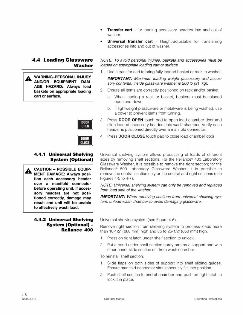
• Transfer cart – for loading accessory headers into and out ofwasher.
• Universal transfer cart – Height-adjustable for transferringaccessories into and out of washer.
4.4 Loading GlasswareWasher
NOTE: To avoid personal injuries, baskets and accessories must beloaded on appropriate loading cart or surface.
1. Use a transfer cart to bring fully loaded basket or rack to washer.
IMPORTANT: Maximum loading weight (accessory and acces-sory contents) inside glassware washer is 200 lb (91 kg).
2. Ensure all items are correctly positioned on rack and/or basket.
a. When loading a rack or basket, beakers must be placedopen end down.
b. If lightweight plasticware or metalware is being washed, usea cover to prevent items from turning.
3. Press DOOR OPEN touch pad to open load chamber door andslide loaded accessory headers into wash chamber. Verify eachheader is positioned directly over a manifold connector.
4. Press DOOR CLOSE touch pad to close load chamber door.
4.4.1 Universal ShelvingSystem (Optional)
Universal shelving system allows processing of loads of differentsizes by removing shelf sections. For the Reliance® 400 LaboratoryGlassware Washer, it is possible to remove the right section; for theReliance® 500 Laboratory Glassware Washer, it is possible toremove the central section only or the central and right sections (seeFigures 4-5 to 4-7).
NOTE: Universal shelving system can only be removed and replacedfrom load side of the washer.
IMPORTANT: When removing sections from universal shelving sys-tem, unload wash chamber to avoid damaging glassware.
4.4.2 Universal ShelvingSystem (Optional) –
Reliance 400
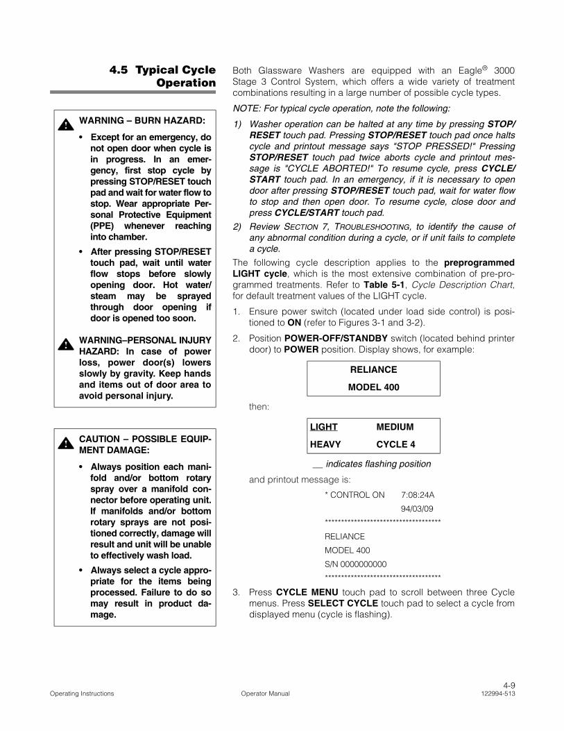
Universal shelving system (see Figure 4-6).
Remove right section from shelving system to process loads morethan 10-1/2" (260 mm) high and up to 25-1/2" (650 mm) high:
1. Press on right latch under shelf section to unlock.
2. Put a hand under shelf section spray arm as a support and withother hand, slide section out from wash chamber.
To reinstall shelf section:
1. Slide flaps on both sides of support into shelf sliding guides.Ensure manifold connector simultaneously fits into position.
2. Push shelf section to end of chamber and push on right latch tolock it in place.
WARNING–PERSONAL INJURYAND/OR EQUIPMENT DAM-AGE HAZARD: Always loadbaskets on appropriate loadingcart or surface.
DOOROPEN
DOORCLOSE
CAUTION – POSSIBLE EQUIP-MENT DAMAGE: Always posi-tion each accessory headerover a manifold connectorbefore operating unit. If acces-sory headers are not posi-tioned correctly, damage mayresult and unit will be unableto effectively wash load.
4-6122994-513 Operator Manual Operating Instructions
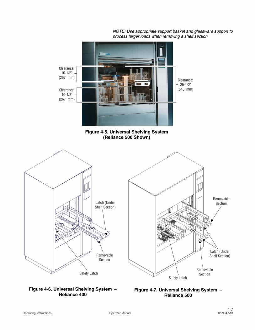
NOTE: Use appropriate support basket and glassware support toprocess larger loads when removing a shelf section.
Figure 4-5. Universal Shelving System (Reliance 500 Shown)
Clearance: 25-1/2"
(648 mm)
Clearance: 10-1/2"
(267 mm)
Clearance: 10-1/2"
(267 mm)
REF.: #920-012-400
Figure 4-6. Universal Shelving System – Reliance 400
Latch (Under Shelf Section)
Removable Section
Safety Latch REF.: #920-012-398
Figure 4-7. Universal Shelving System – Reliance 500
Removable Section
Safety Latch
Removable Section
Latch (Under Shelf Section)
4-7Operating Instructions Operator Manual 122994-513

4.4.3 Universal ShelvingSystem (Optional) –
Reliance 500
Universal shelving system (See Figure 4-7).
It is possible to remove central section only to accommodate twoloads of small items of glassware on each side (up to 10-1/2"[260 mm] high) and a load of larger items (more than 10-1/2"[260 mm] high and up to 25-1/2" [650 mm] high) in the center (seeFigure 4-5).
If a greater loading space is required for larger loads, it is possible toremove central and right sections.
NOTE: Load must not exceed 25-1/2" (260 mm) high.
To remove central section from universal shelving system (seeFigure 4-7):
1. Press on latch located under central shelf section right corner tounlock.
2. Put a hand under shelf section spray arm to support and withother hand, slide section out from wash chamber.
To reinstall central section:
1. Insert flaps on both sides of support into shelf sliding guides.Ensure manifold connector simultaneously fits into position.
2. Push shelf section to end of chamber and push on right latch tolock it in place.
To remove right section from universal shelving system:
1. Press on latch located under right shelf section right corner tounlock.
2. Put a hand under shelf section spray arm to support and withother hand, slide section out from wash chamber.
To reinstall right section:
1. Insert flap from support into shelf sliding guide. Ensure manifoldconnector simultaneously enters into its position.
2. Push shelf to end of chamber and push on right latch to lock it inplace.
NOTE: For the universal shelving system, note the following:
1) Use appropriate support basket and glassware support toprocess larger loads when removing shelf sections.
2) Reliance 500 only: Reinstall right section first on universalshelving system before reinstalling central section.
3) Remove shelf sections before removing entire universalshelving system from unit.
To remove entire universal shelving system:
1. To remove entire universal shelving system, press safety latchon left side of shelf, and slide shelf out of wash chamber (seeFigures 4-6 and 4-7).
2. To replace universal shelving system, align shelf with chamberguides and push shelf into chamber until safety latch locks inplace.
4-8122994-513 Operator Manual Operating Instructions
4.5 Typical CycleOperation
Both Glassware Washers are equipped with an Eagle® 3000Stage 3 Control System, which offers a wide variety of treatmentcombinations resulting in a large number of possible cycle types.
NOTE: For typical cycle operation, note the following:
1) Washer operation can be halted at any time by pressing STOP/RESET touch pad. Pressing STOP/RESET touch pad once haltscycle and printout message says "STOP PRESSED!" PressingSTOP/RESET touch pad twice aborts cycle and printout mes-sage is "CYCLE ABORTED!" To resume cycle, press CYCLE/START touch pad. In an emergency, if it is necessary to opendoor after pressing STOP/RESET touch pad, wait for water flowto stop and then open door. To resume cycle, close door andpress CYCLE/START touch pad.
2) Review SECTION 7, TROUBLESHOOTING, to identify the cause ofany abnormal condition during a cycle, or if unit fails to completea cycle.
The following cycle description applies to the preprogrammedLIGHT cycle, which is the most extensive combination of pre-pro-grammed treatments. Refer to Table 5-1, Cycle Description Chart,for default treatment values of the LIGHT cycle.
1. Ensure power switch (located under load side control) is posi-tioned to ON (refer to Figures 3-1 and 3-2).
2. Position POWER-OFF/STANDBY switch (located behind printerdoor) to POWER position. Display shows, for example:
then:
__ indicates flashing position
and printout message is:
* CONTROL ON 7:08:24A
94/03/09
************************************
RELIANCE
MODEL 400
S/N 0000000000
************************************
3. Press CYCLE MENU touch pad to scroll between three Cyclemenus. Press SELECT CYCLE touch pad to select a cycle fromdisplayed menu (cycle is flashing).
RELIANCE
MODEL 400
LIGHT MEDIUM
HEAVY CYCLE 4
WARNING – BURN HAZARD:
• Except for an emergency, donot open door when cycle isin progress. In an emer-gency, first stop cycle bypressing STOP/RESET touchpad and wait for water flow tostop. Wear appropriate Per-sonal Protective Equipment(PPE) whenever reachinginto chamber.
• After pressing STOP/RESETtouch pad, wait until waterflow stops before slowlyopening door. Hot water/steam may be sprayedthrough door opening ifdoor is opened too soon.
WARNING–PERSONAL INJURYHAZARD: In case of powerloss, power door(s) lowersslowly by gravity. Keep handsand items out of door area toavoid personal injury.
CAUTION – POSSIBLE EQUIP-MENT DAMAGE:
• Always position each mani-fold and/or bottom rotaryspray over a manifold con-nector before operating unit.If manifolds and/or bottomrotary sprays are not posi-tioned correctly, damage willresult and unit will be unableto effectively wash load.
• Always select a cycle appro-priate for the items beingprocessed. Failure to do somay result in product da-mage.
4-9Operating Instructions Operator Manual 122994-513

4. Press CYCLE/START touch pad to select cycle. Name ofselected cycle appears and remains displayed for a few seconds:
__ indicates flashing position
5. Press CYCLE/START touch pad a second time while cyclename is displayed.
NOTE: If CYCLE/START touch pad is not pressed a second timewhile selected cycle name is displayed, screen automaticallyreturns to Cycle menu.
Once cycle is started, printer records:
========================
CYCLE - LIGHT
========================
CYCLE START 8:10:58A
CYCLE DATE 94/03/09
CYCLE NUMBER 0000001
UNIT NUMBER 0000000000
MOTOR SPEED = LOW
NOTE: Programmed pump speed is LOW for Reliance 400 andReliance 500 without universal shelving system. Programmedpump speed is HIGH for Reliance 400 or Reliance 500 with uni-versal shelving system.
6. Cycle proceeds through selected treatments as follows:
NOTE: For cycle treatments, note the following:
1) To extend time of a particular treatment, press EXTENDCYCLE touch pad while reviewing cycle selection, usingREVIEW CYCLE touch pad (see SECTION 4.6, EXTEND CYCLE
TREATMENT). This suspends initial time setting and causestime of the treatment in progress to be multiplied by two.
2) Always use a non-foaming detergent for effective cleaningand proper pump and water-level control operation. Deter-gents with a high chloride content should not be used, aschlorides are harmful to stainless steel. Refer to detergentspecifications in SECTION 2.3, DETERGENTS AND CHEMICAL
ADDITIVES SPECIFICATIONS.
3) Sump may contain water retained from previous cycle. Referto SECTION 5, CYCLE AND CONTROL VALUE PROGRAMMING, forinformation on water save feature.
• Pre-Wash: Load is pre-washed with cold water (maximum 60°F[16°C]) from building supply line for one minute (factory-setting).Water is drained.
PRESS START TO
PROCESS - LIGHT
CYCLESTART
CYCLESTART
WARNING–SLIPPING HAZARD:To prevent slips, keep floorsdry. Promptly clean up anyspills or drippage. For spillsor drippage of detergents orother chemicals, follow safetyprecautions and handling pro-cedures set forth on deter-gent or chemical label and/orMaterial Safety Data Sheet(MSDS).
WARNING – CHEMICAL BURNAND/OR EYE INJURY HAZ-ARD: Detergents are causticand can cause adverse effectsto exposed tissues. Do notget in eyes, on skin or attemptto swallow. Read and followthe precautions and instruc-tions on the detergent labeland in the Material SafetyData Sheet (MSDS) prior tohandling the detergent, refill-ing the detergent container orservicing the detergent injec-tion pump and lines. Wearappropriate Personal Protec-tive Equipment (PPE) when-ever handling the detergent orservicing the detergent injec-tion pump and lines.
4-10122994-513 Operator Manual Operating Instructions
• Wash: Load is washed with detergent injected with water heatedat 150°F (65°C) (factory-setting) for two minutes (factory setting).Water is drained.
• Rinse 1: Load is rinsed with hot tap water (minimum 110°F[43°C]) for 15 seconds (factory-setting). Water is drained.
• Rinse 2: Load is rinsed with hot tap water (minimum 110°F[43°C]) for 15 seconds (factory-setting). Water is drained.
• Pure Water Rinse 1:
For optional pure water tank: Load is rinsed with purified water(minimum 60°F [15°C] from building supply line for 10 seconds,(factory-set, non-recirculated). Water is drained or saved for nextwash (refer to SECTION 5, CYCLE AND CONTROL PROGRAMMING, forinformation on water save feature).
NOTE: If 10 seconds (factory-set) rinse time is increased from00:00 to 15:00, Pure Water Rinse treatment is recirculated.
For standard feature: Load is rinsed with purified water heatedin the sump at 180°F (82°C) for one minute (factory-set,recirculated; refer to Table 5-1, Cycle Description Chart).
• Drying (option): Load is dried at 240°F (116°C) setpoint for15 minutes and one minute cooling by exhaust fan (factory-setting, can be adjusted in Automatic mode).
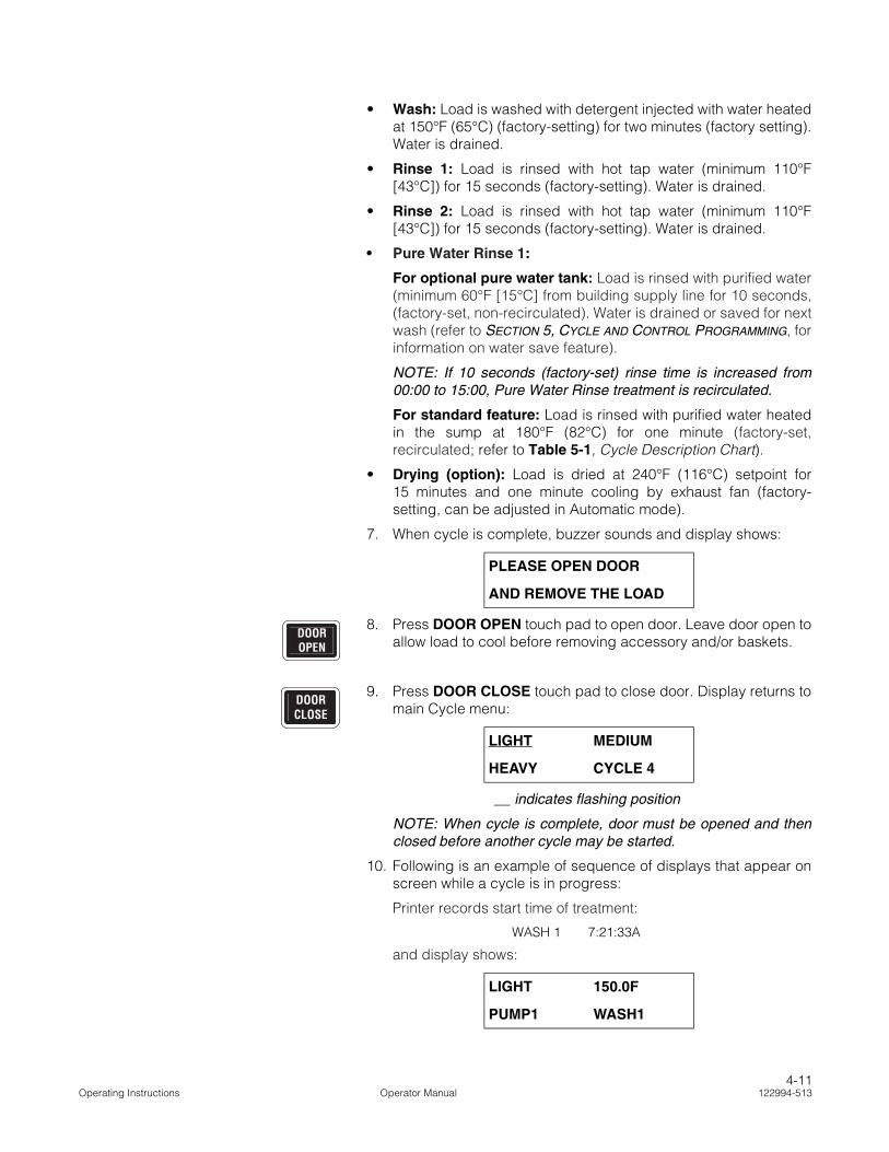
7. When cycle is complete, buzzer sounds and display shows:
8. Press DOOR OPEN touch pad to open door. Leave door open toallow load to cool before removing accessory and/or baskets.
9. Press DOOR CLOSE touch pad to close door. Display returns tomain Cycle menu:
__ indicates flashing position
NOTE: When cycle is complete, door must be opened and thenclosed before another cycle may be started.
10. Following is an example of sequence of displays that appear onscreen while a cycle is in progress:
Printer records start time of treatment:
WASH 1 7:21:33A
and display shows:
PLEASE OPEN DOOR
AND REMOVE THE LOAD
LIGHT MEDIUM
HEAVY CYCLE 4
LIGHT 150.0F
PUMP1 WASH1
DOOROPEN
DOORCLOSE
4-11Operating Instructions Operator Manual 122994-513

alternating with:
NOTE: For cycle treatments, note the following:
1) Time displayed on screen counts down remaining time fortreatment in progress. During Final Rinse treatment, count-down starts only when temperature setpoint is reached.
2) If addition of a powder detergent is programmed for a specifictreatment, powder detergent must be added to sump atbeginning of the treatment. Washer operation automaticallystops before filling phase, alarm buzzer sounds and displayshows: OPEN LOAD DOOR AND ADD POWDER. Operatormust press ALARM REPLY touch pad, open chamber doorand add recommended quantity of powder detergent. Toresume cycle operation, close door and press CYCLE/START touch pad.
then display shows:
alternating with:
then display shows:
alternating with:
LIGHT 150.0F
FILL/INJ TIME = 04:00
LIGHT 150.0F
PUMP1 WASH1
LIGHT 150.0F
CIRCULATE TIME = 01:00
LIGHT 150.0F
PUMP1 WASH1
LIGHT 150.0F
DRAINING TIME = 00:45
4-12122994-513 Operator Manual Operating Instructions
4.6 Extend CycleTreatment
Treatment times may be temporarily extended by pressing EXTENDCYCLE touch pad prior to initiating a cycle during cycle programreview. Temporarily extended treatment times apply only to immedi-ate selected cycle. On completion of cycle, treatment times return toprogrammed settings.
1. Press CYCLE MENU touch pad to scroll through Cycle menusand press SELECT CYCLE touch pad to select cycle.
2. Press REVIEW CYCLE touch pad to access Review mode. Con-tinue to press REVIEW CYCLE touch pad to advance screen todesired treatment. Display shows:
NOTE: Cycle may be started at any point while in Review modeby pressing CYCLE/START touch pad.
3. With correct treatment displayed, press EXTEND CYCLE touchpad. Programmed treatment time is temporarily doubled. IfEXTEND CYCLE touch pad is pressed again, treatment timereturns to original programmed setting. Display shows:
NOTE: While in Review mode, pressing EXTEND CYCLE touchpad only allows operator to double programmed treatment time. Ifa longer treatment time is desired, programmed setting must beadjusted in Change Values mode prior to starting cycle.
4. Press REVIEW CYCLE touch pad again and repeat procedurefor each treatment for which time is to be extended.
5. Press CYCLE/START touch pad while in Review mode to initiatecycle. Cycle automatically progresses through each treatmentas temporarily adjusted in Review mode.
IMPORTANT: To run cycle with extended treatment times, cyclemust be started by pressing CYCLE/START touch pad while inReview mode. If operator reaches PRINT CYCLE VALUES? dis-play and answers YES or NO without starting cycle first, controlexits Review mode. Display screen returns to the Cycle menuand any adjustments made in Review mode are erased.
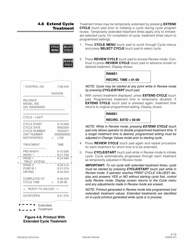
NOTE: Printout generated in Review mode lists programmed (notextended) treatment values. Extended treatments are identifiedon in-cycle printout generated while cycle is in process.
RINSE1
RECIRC. TIME = 01:00
RINSE1
RECIRC. EXTD = 02:00
CYCLEMENU
SELECTCYCLE
REVIEWCYCLE
* CONTROL ON 7:08:24A
94/03/09***********************************RELIANCEMODEL 400S/N 0000000000***********************************========================CYCLE - LIGHT========================CYCLE START 8:10:58ACYCLE DATE 99/03/09CYCLE NUMBER 0000001UNIT NUMBER 0000000000MOTOR SPEED = LOW
TREATMENT TIME------------------------PRE-WASH1 8:10:58AWASH 1 8:21:33ARINSE 1 8:24:49A TREAT. EXTENDRINSE 2 8:28:31APURE W.1 8:31:57ADRYING 8:33:32A
COMPLETED AT 8:48:32ACYCLE TIME = 0:38:36========================= READY TO UNLOAD =========================DOOR OPEN 8:51:37A
ExtendedTreatment
Figure 4-8. Printout With Extended Cycle Treatment
4-13Operating Instructions Operator Manual 122994-513

4.7 AcknowledgeAlarm Condition
If an alarm condition occurs during cycle operation, an alarm buzzersounds to notify operator. Corresponding alarm message screenappears on display, for example:
alternating with:
and printer lists type of alarm and time it occurred:
*ALARM: 3:06:25P
SUMP
TOO LONG IN FILL
NOTE: Review SECTION 7, TROUBLESHOOTING, to identify cause ofany abnormal condition during a cycle or if unit fails to complete acycle.
1. Press ALARM REPLY touch pad to silence alarm buzzer andacknowledge displayed alarm message. Printer records timealarm was acknowledged, for example:
ALARM ACKNOWLEDGED
AT 2:55:00P
and display shows:
alternating with:
2. Press CYCLE/START touch pad to resume cycle operation.Printer prints:
*CYCLE RESUME 3:05:22P
RINSE2 3:06:07P
ALARM: SUMP
TOO LONG IN FILL
CYCLE STOPPED !
PRESS START TO RESUM
ALARM: SUMP
TOO LONG IN FILL
CYCLE STOPPED !
PRESS START TO RESUM
ALARMREPLY
CYCLESTART
4-14122994-513 Operator Manual Operating Instructions
4.8 Stop CycleOperation
NOTE: Washer operation can be halted at any time by pressingSTOP/RESET touch pad. Pressing STOP/RESET touch pad oncehalts cycle and printout message says "STOP PRESSED!" PressingSTOP/RESET touch pad twice aborts cycle and printout message is"CYCLE ABORTED!" To resume cycle, press CYCLE/START touchpad. In an emergency, if it is necessary to open door after pressingSTOP/RESET touch pad, wait for water flow to stop and then opendoor. To resume cycle, close door and press CYCLE/START touchpad.
1. Press STOP/RESET touch pad to immediately halt operation ofcycle in progress. Display screen indicates STOP/RESET touchpad was pressed:
alternating with:
and printer records:
WASH1 2:51:32P
RINSE1 2:54:48P
*STOP PRESSED 2:55:00P
2. Press CYCLE/START touch pad to resume cycle operation.Treatment resumes at point where it was interrupted:
alternating with:
and printer records:
*CYCLE RESUME 2:55:22P
RINSE 2 2:56:07P
STOP WAS PRESSED
PRESS START TO RESUM
LIGHT HOT
RINSE1
LIGHT HOT
RINSE1
LIGHT HOT
DRAINING TIME = 00:45
STOPRESET
CYCLESTART
WARNING – BURN HAZARD:
• Except for an emergency, donot open door when cycle isin progress. In an emer-gency, first stop cycle bypressing STOP/RESET touchpad and wait for water flow tostop. Wear appropriate Per-sonal Protective Equipment(PPE) whenever reachinginto chamber.
• After pressing STOP/RESETtouch pad, wait until waterflow stops before slowlyopening door. Hot water/steam may be sprayedthrough door opening ifdoor is opened too soon.
4-15Operating Instructions Operator Manual 122994-513

4.9 Abort CycleOperation
1. Press STOP/RESET touch pad to halt cycle in progress. Displayshows:
alternating with:
2. Press STOP/RESET touch pad a second time to abort cycle.Display shows:
and printer records:
CYCLE ABORTED 2:42:P
Control automatically aborts cycle operation and returns screento selected Cycle menu:
_Indicates flashing position.
4.10 Shutdown NOTE: Control should be placed in Standby mode after last cycle ofthe day and when washer is not in use for an extended period of time.
At the end of a work session, the washer should be shut down andcleaned thoroughly. Refer to SECTION 6, ROUTINE MAINTENANCE, forcomplete cleaning instructions and scheduled minor maintenance.
1. Position POWER-OFF/STANDBY switch to OFF/STANDBY.Display shows:
2. There is a one-minute countdown before STANDBY cycle starts.
This delay allows operator to cancel STANDBY cycle and comeback to Automatic mode by positioning POWER-OFF/STANDBY back to POWER.
STOP WAS PRESSED
PRESS START TO RESUM
LIGHT HOT
RINSE1
CYCLE ABORTED
LIGHT MEDIUM
HEAVY CYCLE 4
STOPRESET
WARNING – BURN HAZARD:
• Except for an emergency, donot open door when cycle isin progress. In an emer-gency, first stop cycle bypressing STOP/RESET touchpad and wait for water flow tostop. Wear appropriate Per-sonal Protective Equipment(PPE) whenever reachinginto chamber.
• After pressing STOP/RESETtouch pad, wait until waterflow stops before slowlyopening door. Hot water/steam may be sprayedthrough door opening ifdoor is opened too soon.
STANDBY CYCLE WILL
START IN 01:00
4-16122994-513 Operator Manual Operating Instructions

After a one-minute delay, if POWER-OFF/STANDBY is left inOFF/STANDBY position, sump and optional pure water tank aredrained for two minutes. If option applies, drain dischargecooldown system cools effluents before water is sent to drain.Printer records:
STANDBY CYCLE START
2:51:32P
and display shows:
3. When SHUTDOWN cycle is completed and control goes intoStandby mode, interior chamber light remains ON. Printerrecords:
STANDBY CYCLE END
2:53:32P
and display shows:
4. To perform maintenance on washer, position power switch,located behind upper service panel, to OFF.
5. Position building electrical disconnect switch (circuit breaker) toOFF and close building supply lines.
6. Clean unit as described in SECTION 6, ROUTINE MAINTENANCE.
7. Ensure building electrical disconnect switch and power switchare positioned to ON after completion of cleaning and minormaintenance procedures.
NOTE: Leaving power switch to OFF position overnight shortenslife span of battery backed-up control memory.
STANDBY CYCLE TIME
LEFT= 02:00
00:00:00 P
4-17Operating Instructions Operator Manual 122994-513

4.11 Power DoorOperation
Power door is controlled by touch pads located on the control panel(refer to Figure 3-2).
IMPORTANT: Keep chamber door closed between cycles and whenwasher is not in use.
Press DOOR OPEN touch pad to automatically raise door to openposition.
Press DOOR CLOSE touch pad to automatically lower door toclosed position.
If unit is equipped with power double doors, a door-interlock safetyfeature allows only one door to be opened at a time to avoid cross-contamination.
Load door can be operated only from load side control panel, andunload door can be operated only from unload side control panel.Unload side door can be opened ONLY AFTER COMPLETION OFA CYCLE. Load side door can be opened at any time with operatorfollowing appropriate Safety Precautions.
4.11.1 Door Obstruction If an obstruction is present in wash chamber door, do not attempt toremove object. A door safety sensor detects obstruction. Door auto-matically stops from closing and opens completely. An alarm soundsand display shows:
alternating with:
1. Press ALARM REPLY touch pad to silence buzzer.
2. Once door is completely open, carefully remove obstruction fromwash chamber door.
3. Press CYCLE/START touch pad. Door closes and cycle opera-tion resumes.
WARNING – BURN HAZARD:
• Except for an emergency, donot open door when cycle isin progress. In an emer-gency, first stop cycle bypressing STOP/RESET touchpad and wait for water flow tostop. Wear appropriate Per-sonal Protective Equipment(PPE) whenever reachinginto chamber.
• After pressing STOP/RESETtouch pad, wait until waterflow stops before slowlyopening door. Hot water/steam may be sprayedthrough door opening ifdoor is opened too soon.
ALARM:
DOOR OBSTRUCTION
CYCLE STOPPED
PRESS START TO RESUM
WARNING–PERSONAL INJURYAND/OR EQUIPMENT DAM-AGE HAZARD:
• If an obstruction is presentin wash chamber door, doorsafety sensor will detectobstruction and door willautomatically stop closing.Wait until door is fully openand water flow has stoppedbefore removing obstruc-tion.
• If an obstruction is presentin wash chamber door anddoor is unable to raise, DONOT attempt to removeobstruction from underdoor. Door cables may haveloosen which could causedoor to close at high speedwhen obstruction isremoved. Call a qualifiedservice technician to safelyremove an obstruction.
4-18122994-513 Operator Manual Operating Instructions
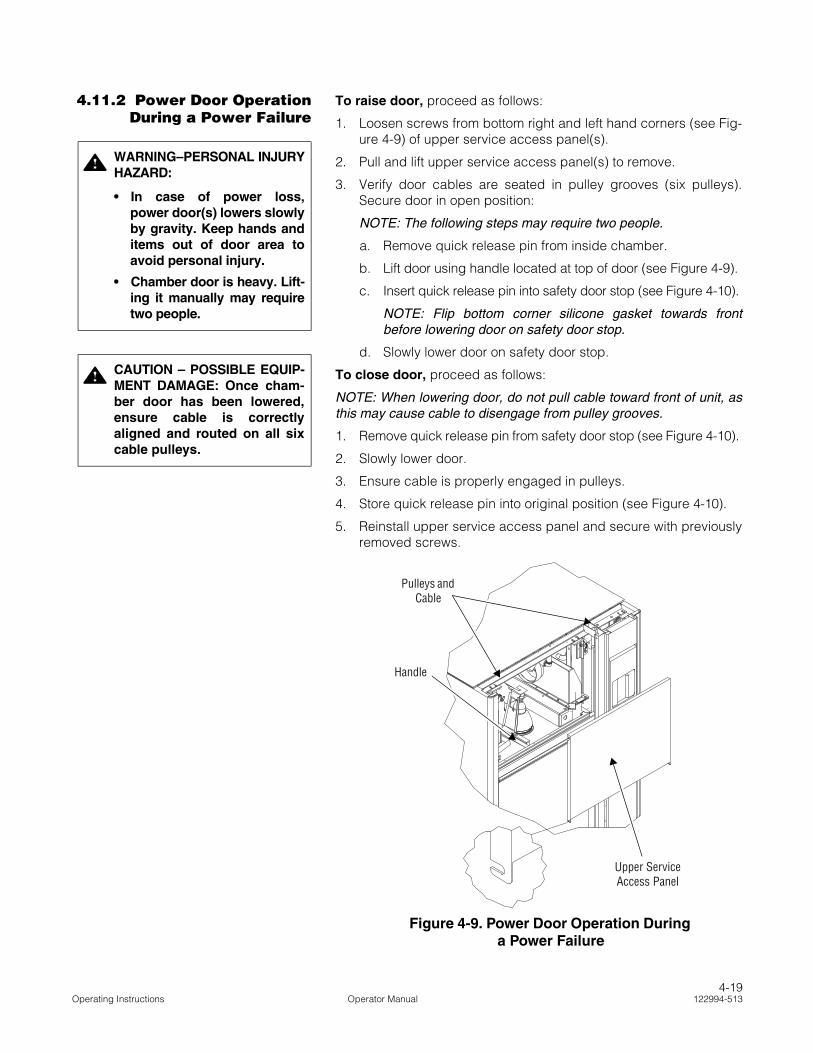
4.11.2 Power Door OperationDuring a Power Failure
To raise door, proceed as follows:
1. Loosen screws from bottom right and left hand corners (see Fig-ure 4-9) of upper service access panel(s).
2. Pull and lift upper service access panel(s) to remove.
3. Verify door cables are seated in pulley grooves (six pulleys).Secure door in open position:
NOTE: The following steps may require two people.
a. Remove quick release pin from inside chamber.
b. Lift door using handle located at top of door (see Figure 4-9).
c. Insert quick release pin into safety door stop (see Figure 4-10).
NOTE: Flip bottom corner silicone gasket towards frontbefore lowering door on safety door stop.
d. Slowly lower door on safety door stop.
To close door, proceed as follows:
NOTE: When lowering door, do not pull cable toward front of unit, asthis may cause cable to disengage from pulley grooves.
1. Remove quick release pin from safety door stop (see Figure 4-10).
2. Slowly lower door.
3. Ensure cable is properly engaged in pulleys.
4. Store quick release pin into original position (see Figure 4-10).
5. Reinstall upper service access panel and secure with previouslyremoved screws.
WARNING–PERSONAL INJURYHAZARD:
• In case of power loss,power door(s) lowers slowlyby gravity. Keep hands anditems out of door area toavoid personal injury.
• Chamber door is heavy. Lift-ing it manually may requiretwo people.
CAUTION – POSSIBLE EQUIP-MENT DAMAGE: Once cham-ber door has been lowered,ensure cable is correctlyaligned and routed on all sixcable pulleys.
REF.: # 920-007-338
Figure 4-9. Power Door Operation During a Power Failure
Upper Service Access Panel
Handle
Pulleys and Cable
4-19Operating Instructions Operator Manual 122994-513

Silicone Gasket
Safety Door Stop
Store Quick Release Pin Into Position
Quick Release Pin
Figure 4-10. Safety Door Stop (Reliance 400 Only)
4-20122994-513 Operator Manual Operating Instructions
5CYCLE AND CONTROL VALUE PROGRAMMING
5.1 General Reliance® 400 Laboratory Glassware Washer and Reliance® 500Laboratory Glassware Washer are programmed at factory for threeoperating cycles:
• LIGHT – For processing lightly soiled or delicate items.
• MEDIUM – For processing beakers, bottles and jars.
• HEAVY – For processing heavily soiled beakers, bottles andjars.
(In addition, a DESCALER cycle is programmed at factory to helpwith routine maintenance. Refer to SECTION 6, ROUTINE MAINTE-NANCE, for more information).
Cycles include various sequences of treatments:
NOTE: See Table 5-1, Cycle Description Chart, for treatment specifi-cations.
• Pre-Wash
• Wash
• Rinse
• Pure Water Rinse
• Drying (option)
Each treatment has time and/or temperature values, some ofwhich can be modified within a range. To help ensure safe andeffective operation, some pre-set values cannot be modified.
IMPORTANT: A listing of the Safety Precautions to be observed when operating and servicing thisglassware washer can be found in SECTION 1 of this manual. Do not operate the equipment until you havebecome familiar with this information.
CAUTION – POSSIBLE EQUIP-MENT DAMAGE: Always selecta cycle appropriate for the itemsbeing processed. Failure to doso may result in product da-mage.
5-1Cycle and Control Value Programming Operator Manual 122994-513
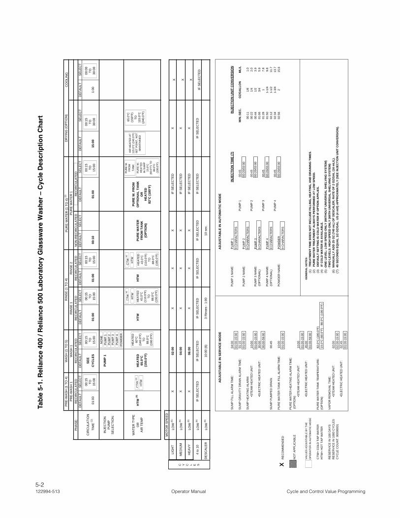
5-2122994-513 Operator Manual Cycle and Control Value Programming
PR
E-W
AS
H (1
TO
4)
WA
SH
(1 T
O 5
)R
INS
E (1
TO
4)
PU
RE
WA
TER
(1 T
O 4
) (2)
D
RY
ING
(OP
TIO
N)
PR
E-W
AS
H 1
WA
SH
1R
INS
E 1
RIN
SE
2P
UR
E W
ATE
R 1
PH
AS
E:
RE
CIR
CU
LATE
DR
EC
IRC
ULA
TED
RE
CIR
CU
LATE
DR
EC
IRC
ULA
TED
NO
N-R
EC
IRC
ULA
TED
RE
CIR
CU
LATE
DD
EFA
ULT
SE
LEC
TD
EFA
ULT
SE
LEC
TD
EFA
ULT
SE
LEC
TD
EFA
ULT
SE
LEC
TD
EFA
ULT
SE
LEC
TD
EFA
ULT
SE
LEC
TD
EFA
ULT
SE
LEC
TD
EFA
ULT
SE
LEC
T
CIR
CU
LATI
ON
SEE
TIM
E(1
)01
:00
CYC
LES
01:0
001
:00
00:1
001
:00
15:0
01:
00
INJE
CTI
ON
PUM
P 1
PU
MP
SE
LEC
TIO
N:
WA
TER
TY
PE
PUR
E W
. FR
OM
OR
HTW
(3)
HEA
TED
HTW
HTW
PUR
E W
ATE
RO
PTIO
NA
L TA
NK
AIR
TE
MP
65.0
°CFR
OM
TA
NK
OR
(150
.0°F
)(O
PTIO
N)
HEA
TED
82°C
(180
°F)
MO
TOR
SP
EE
D
LIG
HT
LOW
(5)
X02
:00
XX
XIF
SE
LEC
TED
X
ME
DIU
MLO
W (5
) X
04:0
0X
XX
IF S
ELE
CTE
DX
HE
AV
YLO
W (5
) X
06:0
0X
XX
IF S
ELE
CTE
DX
4 to
10
LOW
(5)
IF S
ELE
CTE
DIF
SE
LEC
TED
IF S
ELE
CTE
DIF
SE
LEC
TED
IF S
ELE
CTE
DIF
SE
LEC
TED
IF S
ELE
CTE
D
DE
SC
ALE
RLO
W (5
) 10
:00
(6)
3 R
inse
s - 1
:00
10 s
ec.
AD
JUST
AB
LE IN
AU
TOM
ATI
C M
OD
E
SU
MP
FIL
L A
LAR
M T
IME
:04
:00
PU
MP
1 N
AM
E:
PU
MP
1IN
JEC
TIO
N T
IME
(7)
INJE
CTI
ON
UN
IT C
ON
VER
SIO
N01
:00-
15:0
09
CH
AR
AC
TER
SS
UM
P G
RA
VIT
Y D
RA
IN A
LAR
M T
IME
:01
:15
PU
MP
100
:45
MIN
.:SEC
.O
Z/G
ALL
ON
ML/
L01
:00-
15:0
0P
UM
P 2
NA
ME
:P
UM
P 2
00:2
0/03
:00
SU
MP
HE
ATI
NG
ALA
RM
:9
CH
AR
AC
TER
S00
:11
1/8
1.0
•S
TEA
M H
EA
TED
UN
IT:
10:0
0P
UM
P 2
00:4
500
:22
1/4
2.0
01:0
0-15
:00
PU
MP
3 N
AM
E:
PU
MP
300
:20/
03:0
000
:44
1/2
3.9
•E
LEC
TRIC
HE
ATE
D U
NIT
:30
:00
(OP
TIO
NA
L)9
CH
AR
AC
TER
S01
:06
3/4
5.9
30:0
0-59
:00
PU
MP
300
:45
01:2
81
7.8
PU
MP
4 N
AM
E:
PU
MP
400
:20/
03:0
001
:50
1-1/
49.
8S
UM
P P
UM
PE
D D
RA
IN:
00:4
5(O
PTI
ON
AL)
9 C
HA
RA
CTE
RS
02:1
21-
1/2
11.7
PU
MP
400
:45
02:3
41-
3/4
13.7
PU
RE
WA
TER
TA
NK
FIL
L A
LAR
M T
IME
:10
:00
PO
WD
ER
NA
ME
:P
OW
DE
R00
:20/
03:0
002
:56
215
.6R
EC
OM
ME
ND
ED
01:0
0-15
:00
9 C
HA
RA
CTE
RS
PU
RE
WA
TER
HE
ATI
NG
ALA
RM
TIM
E:
NO
T A
PP
LIC
AB
LE (O
PTI
ON
)
•S
TEA
M H
EA
TED
UN
IT:
10:0
001
:00-
15:0
0V
ALU
ES
AD
JUS
TAB
LE B
Y T
HE
•E
LEC
TRIC
HE
ATE
D U
NIT
:45
:00
OP
ER
ATO
R IN
AU
TOM
ATI
C M
OD
E01
:00-
59:0
0(1
) T
REA
TMEN
T TI
ME
DO
ES N
OT
INC
LUD
E FI
LLIN
G, H
EATI
NG
, AN
D D
RA
ININ
G T
IMES
.(2
) P
UR
E W
ATE
R T
REA
TMEN
T A
LWA
YS P
ERFO
RM
ED A
T LO
W S
PEED
.C
TW=
CO
LD T
AP
WA
TER
PU
RE
WA
TER
TA
NK
TE
MP
ER
ATU
RE
:82
.0°C
(180
.0°F
)(3
) D
EFA
ULT
SET
TIN
G IS
CO
LD W
ATE
R IF
OPT
ION
APP
LIES
.H
TW=
HO
T TA
P W
ATE
R(O
PTI
ON
)15
.0°C
(60.
0°F)
- 88
.0°C
(190
.0°F
)(4
) I
F C
OLD
WA
TER
IS A
VAIL
AB
LE.
(5)
-ON
E LE
VEL:
LO
W S
PEED
ON
LY (W
ITH
OU
T U
NIV
ERSA
L SH
ELVI
NG
SYS
TEM
)R
ES
ER
VIC
E IN
100
DA
YS
VA
PO
R R
EM
OV
AL
TIM
E:
-TW
O L
EVEL
S: H
IGH
SPE
ED O
NLY
(WIT
H U
NIV
ERSA
L SH
ELVI
NG
SYS
TEM
)R
ES
ER
VIC
E IN
100
0 C
YC
LES
•S
TEA
M H
EA
TED
UN
IT:
02:0
0(6
) M
AN
UA
LLY
AD
D 2
5 O
Z (7
40 m
L) O
F D
ESC
ALE
R; R
ATE
OF
2 O
Z/G
AL
(16
mL/
L).
CY
CLE
CO
UN
T: 0
0000
001
02:0
0-15
:00
(7)
45
SEC
ON
DS
EQU
AL
1/2
OZ/
GA
L. U
S (4
ml/l
) APP
RO
XIM
ATE
LY (S
EE IN
JEC
TIO
N U
NIT
CO
NVE
RSI
ON
).
•ELE
CTR
IC H
EA
TED
UN
IT:
02:4
5R
EV
ISIO
N 1
3 (2
006-
12-1
4)01
:00-
15:0
0R
EF.
: #12
2-99
7-30
4
GEN
ERA
L N
OTE
S:
AD
JUST
AB
LE IN
SER
VIC
E M
OD
E
IF S
ELE
CTE
D
CO
OLI
NG
X X X
C Y C L E S
00:1
5TO 15
:00
00:1
5TO 15
:00
00:1
5TO 15
:00
00:1
5TO 15
:00
00:1
5TO 15
:00
00:1
5TO 30
:00
CTW
(4)
HTW
CTW
(4)
HTW
CTW
(4)
HTW
HE
ATE
D60
°C(1
40.0
°F)
TO88
.0°C
(190
.0°F
)
HE
ATE
D43
.0°C
(110
.0°F
)TO
88.0
°C(1
90.0
°F)
PU
RE
W.
HE
ATE
DIN
SU
MP
15
.0°C
(60.
0°F)
TO
88.0
°C(1
90.0
°F)
PU
RE
W.
FRO
MTA
NK
65.0
°C(1
50°F
)TO
115.
0°C
(240
.0°F
)
PO
WD
ER
PU
MP
4P
UM
P 3
PU
MP
2P
UM
P 1
NO
NE
X
AIR
HE
ATE
D A
T 11
5.0°
C (2
40.0
°F)
SE
T P
OIN
T, N
OT
MA
INTA
INE
DH
EA
TED
43.0
°C(1
10.0
°F)
TO88
.0°C
(190
.0°F
)
00:0
0TO 30
:00
Tab
le 5
-1. R
elia
nce
400
/ R
elia
nce
500
Lab
ora
tory
Gla
ssw
are
Was
her
– C
ycle
Des
crip
tio
n C
har
t
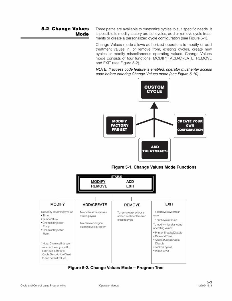
5.2 Change ValuesMode
Three paths are available to customize cycles to suit specific needs. Itis possible to modify factory pre-set cycles, add or remove cycle treat-ments or create a personalized cycle configuration (see Figure 5-1).
Change Values mode allows authorized operators to modify or addtreatment values in, or remove from, existing cycles, create newcycles or modify miscellaneous operating values. Change Valuesmode consists of four functions: MODIFY, ADD/CREATE, REMOVEand EXIT (see Figure 5-2).
NOTE: If access code feature is enabled, operator must enter accesscode before entering Change Values mode (see Figure 5-10).
CUSTOMCYCLE
MODIFYFACTORYPRE-SET
ADDTREATMENTS
CREATE YOUROWN
CONFIGURATION
Figure 5-1. Change Values Mode Functions
STATUS
MODIFY ADDREMOVE EXIT
MODIFYMODIFYMODIFYMODIFYMODIFY
To modify Treatment Values• Time• Temperature• Chemical Injection Pump• Chemical Injection Rate*
* Note: Chemical injection rate can be adjusted for each cycle. Refer to Cycle Description Chart, to see default values.
ADD/CREATEADD/CREATEADD/CREATEADD/CREATEADD/CREATE
To add treatments to anexisting cycle
To create an originalcustom cycle program
EXITEXITEXITEXITEXIT
To start cycle with freshwater
To print cycle values
To modify miscellaneousoperating values:
• Printer Enable/Disable• Date and Time• Access Code Enable/ Disable• Lockout cycles• Water saver
REMOVEREMOVEREMOVEREMOVEREMOVE
To remove a previouslyadded treatment from anexisting cycle
Figure 5-2. Change Values Mode – Program Tree
5-3Cycle and Control Value Programming Operator Manual 122994-513

5.3 TreatmentSequence and Display
Screens
In Change Values mode, cycles are modified or created by selectinga treatment, then modifying values on a series of display screens.Process is repeated for each selected treatment until a customizedcycle is complete.
The six cycle treatment types available occur in a sequential orderwhich may not be changed. Treatments may be added or removedentirely from the operating sequence; however, control only allowsplacement of treatments that follow normal sequence. For example,a Pre-Wash treatment added to the cycle always occurs after anexisting Pre-Wash treatment, never after a Wash treatment.
Treatments and corresponding treatment value screens occur in thefollowing order:
• Pre-Wash (one to four Pre-Wash treatments available):
__ indicates flashing position
followed by:
__ indicates flashing position
• Wash (one to five Wash treatments available):
__ indicates flashing position
followed by:
__ indicates flashing position
followed by:
__ indicates flashing position
• Rinse (one to four Rinse treatments available):
Rinse 1:
__ indicates flashing position
SELECT WATER TEMP.
COLD HOT
PRE-WASH1
XX:XX
SELECT WATER TEMP.
HOT HEATED
PUMP1 WASH1
XX:XX TMP=XXX.XF
DETERGENT TO INJECT?
PUMP1
SELECT WATER TEMP.
COLD HOT HEATED
5-4122994-513 Operator Manual Cycle and Control Value Programming
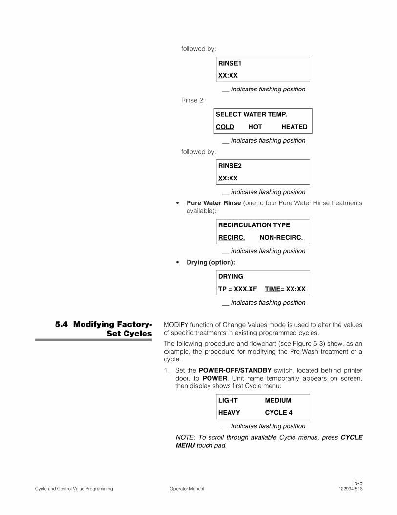
followed by:
__ indicates flashing position
Rinse 2:
__ indicates flashing position
followed by:
__ indicates flashing position
• Pure Water Rinse (one to four Pure Water Rinse treatmentsavailable):
__ indicates flashing position
• Drying (option):
__ indicates flashing position
5.4 Modifying Factory-Set Cycles
MODIFY function of Change Values mode is used to alter the valuesof specific treatments in existing programmed cycles.
The following procedure and flowchart (see Figure 5-3) show, as anexample, the procedure for modifying the Pre-Wash treatment of acycle.
1. Set the POWER-OFF/STANDBY switch, located behind printerdoor, to POWER. Unit name temporarily appears on screen,then display shows first Cycle menu:
__ indicates flashing position
NOTE: To scroll through available Cycle menus, press CYCLEMENU touch pad.
RINSE1
XX:XX
SELECT WATER TEMP.
COLD HOT HEATED
RINSE2
XX:XX
RECIRCULATION TYPE
RECIRC. NON-RECIRC.
DRYING
TP = XXX.XF TIME= XX:XX
LIGHT MEDIUM
HEAVY CYCLE 4
5-5Cycle and Control Value Programming Operator Manual 122994-513

SELECTCYCLE
STATUS
To ModifyCycle
ConfirmSelection
STATUS
STATUS
Value screensequencecorresponds toselected treatment.
SAVEVALUES
POWER
OFF
STANDBY
Press SELECTSELECTSELECTSELECTSELECTCYCLECYCLECYCLECYCLECYCLE to selectcycle to modify.
Press VALUEVALUEVALUEVALUEVALUE andCURSORCURSORCURSORCURSORCURSOR arrows toselect characters tobe modified.
Pressing SAVE VALUESSAVE VALUESSAVE VALUESSAVE VALUESSAVE VALUESsaves previously changedvalues and returns screen toCycle menu.
ConfirmSelection
ConfirmSelection
ConfirmSelection
ConfirmSelection
Press VALUEVALUEVALUEVALUEVALUEarrows to selecttreatment to bemodified.
Press CURSORCURSORCURSORCURSORCURSORarrows to selectwater temperature.
STATUS
STATUS
STATUS
STATUS
STATUS
Pressing SAVESAVESAVESAVESAVEVALUESVALUESVALUESVALUESVALUES savespreviously changedvalues and returnsscreen to Cycle menu.
Repeat MODIFY sequence
EXIT to Misc. Values
STATUS
STATUS
STATUS
CHANGEVALUES
CHANGEVALUES GO TOGO TOGO TOGO TOGO TO
FIGURE 5-7FIGURE 5-7FIGURE 5-7FIGURE 5-7FIGURE 5-7
SAVEVALUES
SAVEVALUES
SAVEVALUES
STATUS
* RELIANCE * * MODEL 400 *
LIGHT MEDIUMHEAVY CYCLE 4
CHANGEVALUES
CVTP=MODIFY CYCLESVTP=ERASE CYCLE
CHANGEVALUES
CHANGE CYCLE NAMELIGHT
CHANGEVALUES
MODIFY ADDREMOVE EXIT
CHANGEVALUES
MODIFY TREATMENTPRE-WASH1
CHANGEVALUES
SELECT WATER TEMP.COLD HOT
CHANGEVALUES
PRE-WASH 101:00
CHANGEVALUES
MODIFY ADDREMOVE EXIT
MODIFY ADDREMOVE EXIT
MODIFY ADDREMOVE EXIT
LIGHT MEDIUMHEAVY CYCLE 4
SAVEVALUES
ToEraseCycle
ConfirmSelection
Figure 5-3. Change Values Mode – Modifying Cycle Treatments
5-6122994-513 Operator Manual Cycle and Control Value Programming

2. Press SELECT CYCLE touch pad until desired cycle nameflashes:
__ indicates flashing position
3. When desired cycle name is flashing, press CHANGE VALUEStouch pad to access Change Values mode. Printer records:
*CHANGE VALUE 8:44:51A
and display shows:
NOTE: When modifying a cycle, note the following:
1) Pressing SAVE VALUES touch pad erases the selectedcycle from control memory. Cycle reverts to a numberedunprogrammed listing on the Cycle menu.
2) If access code feature is enabled and the selected cycle islocked out, the access code sequence (see Figure 5-10)appears after CHANGE VALUES touch pad is pressed.
3) New value entries must be confirmed by pressing CHANGEVALUES touch pad. Change Values mode may be exited at anytime by pressing SAVE VALUES touch pad. Control saves con-firmed values and returns screen to selected Cycle menu.
4. Press CHANGE VALUES touch pad. Change Cycle Namescreen appears:
__ indicates flashing position
5. Press CHANGE VALUES touch pad. Change Values menuscreen appears:
__ indicates flashing position
6. Press CHANGE VALUES touch pad to confirm MODIFY functionselection. Modify Treatment screen appears:
__ indicates flashing position
Press VALUE arrows (up or down) to scroll through treatmentsuntil desired treatment name is flashing.
LIGHT MEDIUM
HEAVY CYCLE 4
CVTP = MODIFY CYCLE
SVTP = ERASE CYCLE
CHANGE CYCLE NAME
LIGHT
MODIFY ADD
REMOVE EXIT
MODIFY TREATMENT
PRE-WASH 1
SELECTCYCLE
CHANGEVALUES
CHANGEVALUES
CHANGEVALUES
CHANGEVALUES
VALUE
5-7Cycle and Control Value Programming Operator Manual 122994-513
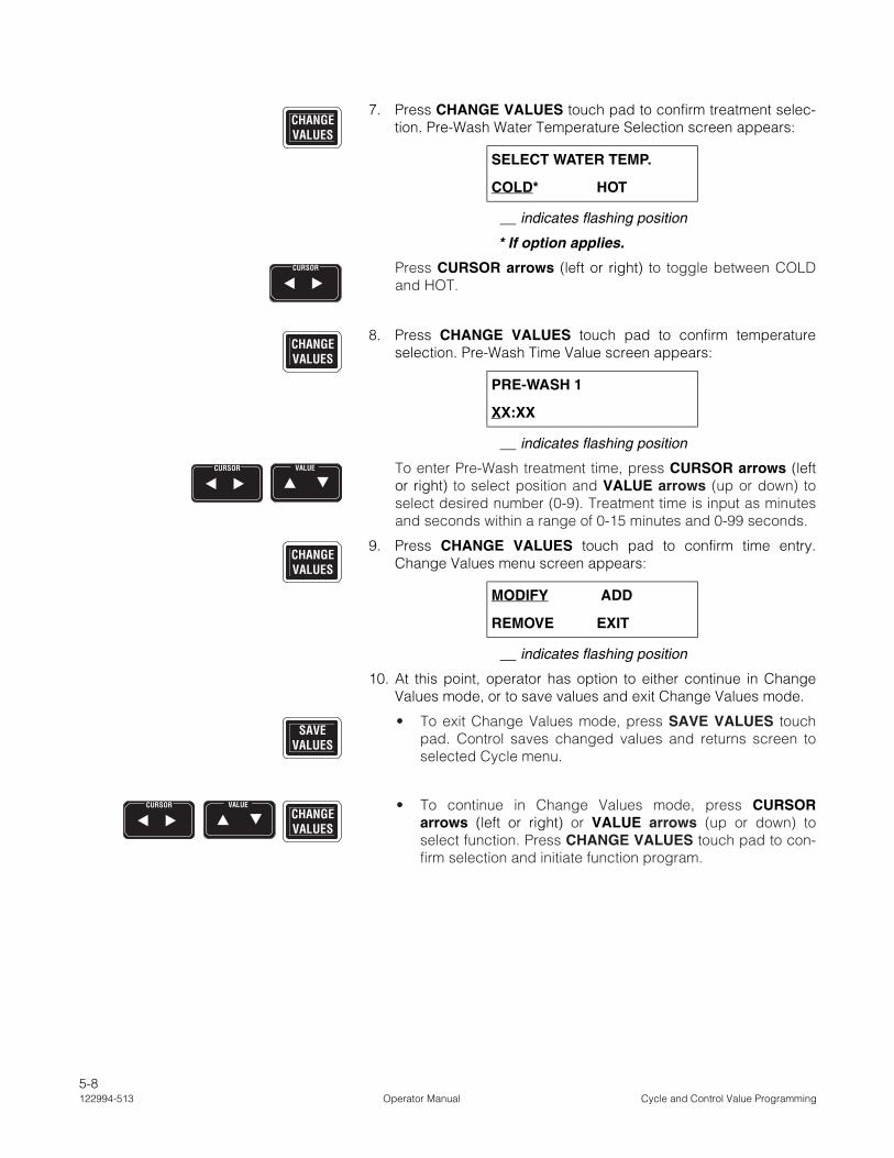
7. Press CHANGE VALUES touch pad to confirm treatment selec-tion. Pre-Wash Water Temperature Selection screen appears:
__ indicates flashing position
* If option applies.
Press CURSOR arrows (left or right) to toggle between COLDand HOT.
8. Press CHANGE VALUES touch pad to confirm temperatureselection. Pre-Wash Time Value screen appears:
__ indicates flashing position
To enter Pre-Wash treatment time, press CURSOR arrows (leftor right) to select position and VALUE arrows (up or down) toselect desired number (0-9). Treatment time is input as minutesand seconds within a range of 0-15 minutes and 0-99 seconds.
9. Press CHANGE VALUES touch pad to confirm time entry.Change Values menu screen appears:
__ indicates flashing position
10. At this point, operator has option to either continue in ChangeValues mode, or to save values and exit Change Values mode.
• To exit Change Values mode, press SAVE VALUES touchpad. Control saves changed values and returns screen toselected Cycle menu.
• To continue in Change Values mode, press CURSORarrows (left or right) or VALUE arrows (up or down) toselect function. Press CHANGE VALUES touch pad to con-firm selection and initiate function program.
SELECT WATER TEMP.
COLD* HOT
PRE-WASH 1
XX:XX
MODIFY ADD
REMOVE EXIT
CHANGEVALUES
CURSOR
CHANGEVALUES
CURSOR VALUE
CHANGEVALUES
SAVEVALUES
CHANGEVALUES
CURSOR VALUE
5-8122994-513 Operator Manual Cycle and Control Value Programming

5.5 Adding CycleTreatments
ADD function of Change Values mode is used to insert treatments inthe operating sequence of a programmed cycle.
NOTE: A total of 15 programmed treatments are allowed in a cycle.Total allowed number of each treatment type varies. See Table 5-1,Cycle Description Chart, for specific treatment parameters.
The following procedure and flowchart (see Figure 5-4) show, as anexample, procedure for adding a new Pre-Wash treatment to acycle.
1. Set POWER-OFF/STANDBY switch, located behind printerdoor, to POWER. Unit name temporarily appears on screen,then screen displays first Cycle menu:
__ indicates flashing position
NOTE: To scroll through available Cycle menus, press CYCLEMENU touch pad.
2. Press SELECT CYCLE touch pad until desired cycle nameflashes:
__ indicates flashing position
3. When desired cycle name is flashing, press CHANGE VALUEStouch pad to access the Change Values mode. Printer records:
*CHANGE VALUE 8:44:51A
and following screen appears:
NOTE: When changing a cycle, note the following:
1) Pressing SAVE VALUES touch pad erases selected cyclefrom control memory. Cycle reverts to a numbered unpro-grammed listing on Cycle menu.
2) If access code feature is enabled and selected cycle islocked out, access code sequence (see Figure 5-10) appearsafter CHANGE VALUES touch pad is pressed.
3) Change Values mode may be exited at any time by pressingSAVE VALUES touch pad. New value entries must be con-firmed by pressing CHANGE VALUES touch pad. Controlsaves confirmed values and returns screen to selected Cyclemenu.
LIGHT MEDIUM
HEAVY CYCLE 4
LIGHT MEDIUM
HEAVY CYCLE 4
CVTP = MODIFY CYCLE
SVTP = ERASE CYCLE
SELECTCYCLE
CHANGEVALUES
5-9Cycle and Control Value Programming Operator Manual 122994-513

STATUS
STATUS
Pressing SAVE VALUESSAVE VALUESSAVE VALUESSAVE VALUESSAVE VALUESsaves previously changedvalues and returns screen toCycle menu.
STATUS
STATUS
Value screensequencecorresponds toselectedtreatment.
STATUS
To ModifyCycle
ConfirmSelection
STATUS
STATUS
SAVEVALUES
Press CYCLECYCLECYCLECYCLECYCLEMENUMENUMENUMENUMENU to scrollcycle menus andSELECT CYCLESELECT CYCLESELECT CYCLESELECT CYCLESELECT CYCLE toselect cycle.
ConfirmSelection
ConfirmSelection
Press CURSORCURSORCURSORCURSORCURSORarrows to selectwater temperature.
STATUS
Repeat ADD sequence
EXIT to Misc. Values
STATUS
STATUS
STATUS
CHANGEVALUES
CHANGEVALUES GO TOGO TOGO TOGO TOGO TO
FIGURE 5-7FIGURE 5-7FIGURE 5-7FIGURE 5-7FIGURE 5-7
SAVEVALUES
SAVEVALUES
STATUS
ConfirmSelection
Pressing SAVESAVESAVESAVESAVEVALUESVALUESVALUESVALUESVALUES savespreviously changedvalues and returnsscreen to Cyclemenu.SAVE
VALUES
ConfirmSelection
Press VALUEVALUEVALUEVALUEVALUEarrows to selecttreatment after whichto add a newtreatment.
STATUS
ConfirmSelection
STATUS
POWER
OFF
STANDBY
ConfirmSelection
* RELIANCE * * MODEL 400 *
LIGHT MEDIUMHEAVY CYCLE 4
CHANGEVALUES
CVTP=MODIFY CYCLESVTP=ERASE CYCLE
CHANGEVALUES
CHANGE CYCLE NAMEMEDIUM
CHANGEVALUES
MODIFY ADDREMOVE EXIT
CHANGEVALUES
CREATE TREAT. AFTERPRE-WASH 1
CHANGEVALUES
SCROLL TREAT. TO ADDPRE-WASH 2
CHANGEVALUES
INITIALIZINGTREATMENT...
SELECT WATER TEMP.COLD HOT
CHANGEVALUES
PRE-WASH 201:00
CHANGEVALUES
MODIFY ADDREMOVE EXIT
MODIFY ADDREMOVE EXIT
MODIFY ADDREMOVE EXIT
LIGHT MEDIUMHEAVY CYCLE 4
SAVEVALUES
To EraseCycle
Figure 5-4. Change Values Mode – Adding Cycle Treatments
5-10122994-513 Operator Manual Cycle and Control Value Programming

4. When desired cycle name is flashing, press CHANGE VALUEStouch pad to access Change Values mode. Display shows:
__ indicates flashing position
To change cycle name, press CURSOR arrows (left or right) toselect position and VALUE arrows (up or down) to selectdesired letter, number, punctuation or space. Cycle name canbe a maximum of nine characters, including spaces.
5. Press CHANGE VALUES touch pad. Change Values menuscreen appears:
__ indicates flashing position
6. Press CURSOR arrows (left or right) or VALUE arrows (up ordown) to select ADD function:
__ indicates flashing position
7. Press CHANGE VALUES touch pad to confirm ADD functionselection. Create Treatment screen appears:
__ indicates flashing position
NOTE: If only one treatment is programmed in the cycle, or if it ispossible to add only one treatment type, display goes directly toScroll Treatment to Add screen:
To select position in cycle where treatment is added, pressVALUE arrows (up or down) to scroll through treatments untiltreatment name is flashing.
IMPORTANT: If Pre-Wash treatment has been deleted, it is notpossible to add a treatment before Wash treatment. Control doesnot allow restoring Pre-Wash treatment into cycle. In this case,erase whole cycle and create a new one starting with a Pre-Washtreatment so you can add desired treatments after Pre-Washtreatment.
CHANGE CYCLE NAME
MEDIUM
MODIFY ADD
REMOVE EXIT
MODIFY ADD
REMOVE EXIT
CREATE TREAT. AFTER
PRE-WASH 1
CHANGEVALUES
CURSOR VALUE
CHANGEVALUES
CURSOR VALUE
CHANGEVALUES
VALUE
5-11Cycle and Control Value Programming Operator Manual 122994-513

8. Press CHANGE VALUES touch pad to confirm additional treat-ment is added after selected treatment. Add Treatment screenappears:
__ indicates flashing position
Press VALUE arrows (up or down) to scroll through treatmentsuntil desired treatment name is flashing.
9. Press CHANGE VALUES touch pad to confirm and add selectedtreatment to programmed cycle. The Treatment Initializationscreen appears:
then Pre-Wash Water Temperature Selection screen appears:
__ indicates flashing position
* If option applies.
Press CURSOR arrows (left or right) to toggle between COLDand HOT.
10. Press CHANGE VALUES touch pad to confirm temperatureselection. Pre-Wash Time Value screen appears:
__ indicates flashing position
To enter Pre-Wash treatment time, press CURSOR arrows (leftor right) to select position and VALUE arrows (up or down) toselect desired number (0-9). Treatment time is input as minutesand seconds within a range of 0-15 minutes and 0-99 seconds.
11. Press CHANGE VALUES touch pad to confirm time entry.Change Values menu screen appears:
__ indicates flashing position
SCROLL TREAT. TO ADD
PRE-WASH
INITIALIZING
TREATMENT...
SELECT WATER TEMP.
COLD* HOT
PRE-WASH 2
XX:XX
MODIFY ADD
REMOVE EXIT
CHANGEVALUES
VALUE
CHANGEVALUES
CURSOR
CHANGEVALUES
CURSOR VALUE
CHANGEVALUES
5-12122994-513 Operator Manual Cycle and Control Value Programming
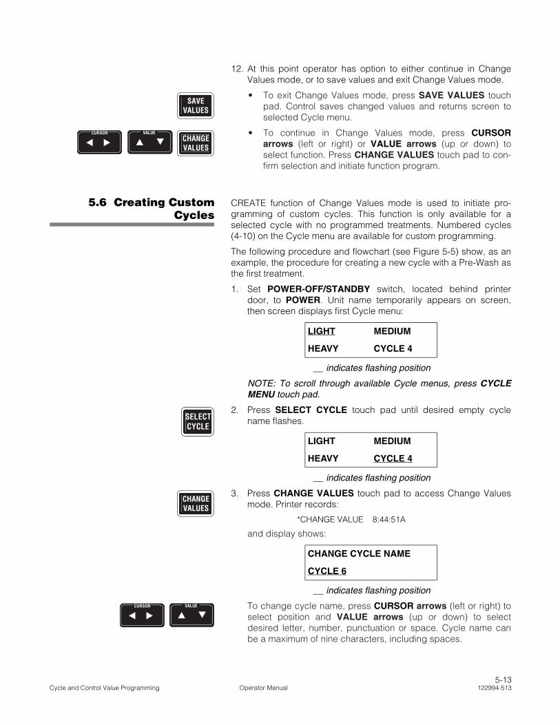
12. At this point operator has option to either continue in ChangeValues mode, or to save values and exit Change Values mode.
• To exit Change Values mode, press SAVE VALUES touchpad. Control saves changed values and returns screen toselected Cycle menu.
• To continue in Change Values mode, press CURSORarrows (left or right) or VALUE arrows (up or down) toselect function. Press CHANGE VALUES touch pad to con-firm selection and initiate function program.
5.6 Creating CustomCycles
CREATE function of Change Values mode is used to initiate pro-gramming of custom cycles. This function is only available for aselected cycle with no programmed treatments. Numbered cycles(4-10) on the Cycle menu are available for custom programming.
The following procedure and flowchart (see Figure 5-5) show, as anexample, the procedure for creating a new cycle with a Pre-Wash asthe first treatment.
1. Set POWER-OFF/STANDBY switch, located behind printerdoor, to POWER. Unit name temporarily appears on screen,then screen displays first Cycle menu:
__ indicates flashing position
NOTE: To scroll through available Cycle menus, press CYCLEMENU touch pad.
2. Press SELECT CYCLE touch pad until desired empty cyclename flashes.
__ indicates flashing position
3. Press CHANGE VALUES touch pad to access Change Valuesmode. Printer records:
*CHANGE VALUE 8:44:51A
and display shows:
__ indicates flashing position
To change cycle name, press CURSOR arrows (left or right) toselect position and VALUE arrows (up or down) to selectdesired letter, number, punctuation or space. Cycle name canbe a maximum of nine characters, including spaces.
SAVEVALUES
CHANGEVALUES
CURSOR VALUE
LIGHT MEDIUM
HEAVY CYCLE 4
LIGHT MEDIUM
HEAVY CYCLE 4
CHANGE CYCLE NAME
CYCLE 6
SELECTCYCLE
CHANGEVALUES
CURSOR VALUE
5-13Cycle and Control Value Programming Operator Manual 122994-513

Value screensequencecorresponds toselected treatment.
Pressing SAVESAVESAVESAVESAVEVALUESVALUESVALUESVALUESVALUES savespreviouslychanged valuesand returnsscreen to Cyclemenu.
STATUS
Pressing SAVE VALUESSAVE VALUESSAVE VALUESSAVE VALUESSAVE VALUESsaves previously changedvalues and returns screen toCycle menu.
ConfirmSelection
ConfirmSelection
Press CURSORCURSORCURSORCURSORCURSORarrows to selectwater temperature.
STATUS
STATUS
STATUS
SAVEVALUES
STATUS
STATUS
To ModifyCycle
ConfirmSelection
ConfirmSelection
STATUS
STATUS
Press CYCLECYCLECYCLECYCLECYCLEMENUMENUMENUMENUMENU to scrollcycle menus andSELECT CYCLESELECT CYCLESELECT CYCLESELECT CYCLESELECT CYCLE toselect an emptycycle.
ConfirmSelection
Press VALUEVALUEVALUEVALUEVALUEarrows to selecttreatment to bemodified.
STATUS
STATUS
ConfirmSelection
SAVEVALUES
Go to ADD sequence
EXIT to Misc. Values
STATUS
STATUS
STATUS
CHANGEVALUES
CHANGEVALUES GO TOGO TOGO TOGO TOGO TO
FIGURE 5-7FIGURE 5-7FIGURE 5-7FIGURE 5-7FIGURE 5-7
SAVEVALUES
GO TOGO TOGO TOGO TOGO TOFIGURE 5-4FIGURE 5-4FIGURE 5-4FIGURE 5-4FIGURE 5-4
POWER
OFF
STANDBY
Press VALUE arrowsVALUE arrowsVALUE arrowsVALUE arrowsVALUE arrowsand CURSOR arrowsCURSOR arrowsCURSOR arrowsCURSOR arrowsCURSOR arrowsto select characters tomodify.
* RELIANCE * * MODEL 400 *
LIGHT MEDIUMHEAVY CYCLE 4
CHANGEVALUES
CVTP=MODIFY CYCLESVTP=ERASE CYCLE
CHANGEVALUES
CHANGE CYCLE NAMECYCLE 7
CHANGEVALUES
MODIFY CREATEREMOVE EXIT
CHANGEVALUES
SCROLL TREAT. TO ADDPRE-WASH
CHANGEVALUES
INITIALIZINGTREATMENT...
SELECT WATER TEMP.COLD HOT
CHANGEVALUES
PRE-WASH 101:00
CHANGEVALUES
MODIFY ADDREMOVE EXIT
SAVEVALUES
SAVEVALUES
To EraseCycle
MODIFY ADDREMOVE EXIT
MODIFY ADDREMOVE EXIT
LIGHT MEDIUMHEAVY CYCLE 4
Figure 5-5. Change Values Mode – Creating Custom Cycles
5-14122994-513 Operator Manual Cycle and Control Value Programming

NOTE: Change Values mode may be exited at any time bypressing SAVE VALUES touch pad. New value entries must beconfirmed by pressing CHANGE VALUES touch pad. Controlsaves confirmed values and return screen to selected Cyclemenu.
4. Press CHANGE VALUES touch pad. Change Values menuscreen appears:
__ indicates flashing position
NOTE: CREATE function is displayed only when creating firsttreatment of a custom cycle. To continue programming customcycle, use ADD function.
5. Press CHANGE VALUES touch pad to confirm CREATE functionselection. Add Treatment screen appears:
__ indicates flashing position
Press VALUE arrows (up or down) to scroll through treatmentsuntil desired treatment name is flashing.
IMPORTANT: When developing a custom cycle, operator mustbe accurate in selecting first treatment of cycle. Control onlyallows placement of treatments that follow normal sequence. Forexample, if first treatment selected was a Wash treatment, it isnot possible to add a Pre-Wash treatment to the cycle.
NOTE: If maximum number of treatment type selected allowed incycle is reached (see Table 5-1, Cycle Description Chart),display shows: NO ROOM IN THIS TREATMENT TYPE.
6. Press CHANGE VALUES touch pad to confirm and addselected treatment to custom cycle. Treatment Initializationscreen appears:
...then Pre-Wash Water Temperature Selection screen appears:
__ indicates flashing position
* If option applies.
Press CURSOR arrows (left or right) to toggle between COLDand HOT.
MODIFY CREATE
REMOVE EXIT
SCROLL TREAT. TO ADD
PRE-WASH 1
INITIALIZING
TREATMENT...
SELECT WATER TEMP.
COLD HOT
CHANGEVALUES
CHANGEVALUES
VALUE
CHANGEVALUES
CURSOR
5-15Cycle and Control Value Programming Operator Manual 122994-513

7. Press CHANGE VALUES touch pad to confirm temperatureselection. Pre-Wash Time Value screen appears:
__ indicates flashing position
To enter Pre-Wash treatment time, press CURSOR arrows (leftor right) to select position and VALUE arrows (up or down) toselect desired number (0-9). Treatment time is input as minutesand seconds within a range of 0-15 minutes and 0-99 seconds.
8. Press CHANGE VALUES touch pad to confirm time entry.Change Values menu screen appears:
__ indicates flashing position
9. At this point, operator has the option to either continue inChange Values Mode, or to save values and exit Change Valuesmode.
• To exit Change Values mode, press SAVE VALUES. Controlsaves changed values and returns screen to selected Cyclemenu.
• To continue in Change Values mode, press CURSORarrows (left or right) or VALUE arrows (up or down) toselect function. Press CHANGE VALUES touch pad to con-firm selection and initiate function program.
5.7 RemovingTreatments From
Cycles
REMOVE function of the Change Values mode is used to deletetreatments from a programmed cycle.
The following procedure and flowchart (see Figure 5-6) show, as anexample, the procedure for deleting Pre-Wash treatment from acycle.
1. Set POWER-OFF/STANDBY switch, located behind printerdoor, to POWER. Unit name temporarily appears on screen,then screen displays first Cycle menu:
__ indicates flashing position
NOTE: To scroll through available Cycle menus, press CYCLEMENU touch pad.
PRE-WASH
XX:XX
MODIFY ADD
REMOVE EXIT
CHANGEVALUES
CURSOR VALUE
CHANGEVALUES
SAVEVALUES
CHANGEVALUES
CURSOR VALUE
LIGHT MEDIUM
HEAVY CYCLE 4
5-16122994-513 Operator Manual Cycle and Control Value Programming

Pressing SAVESAVESAVESAVESAVEVALUESVALUESVALUESVALUESVALUES savespreviouslychanged valuesand returnsscreen to Cyclemenu.
STATUS
Pressing SAVE VALUESSAVE VALUESSAVE VALUESSAVE VALUESSAVE VALUESsaves previously changedvalues and returns screen toCycle menu.
ConfirmSelection
STATUS
STATUS
STATUS
To ModifyCycle
ConfirmSelection
ConfirmSelection
STATUS
STATUS
Press CYCLECYCLECYCLECYCLECYCLEMENUMENUMENUMENUMENU to scrollcycle menus andSELECT CYCLESELECT CYCLESELECT CYCLESELECT CYCLESELECT CYCLE toselect an emptycycle.
ConfirmSelection
Press VALUEVALUEVALUEVALUEVALUEarrows to selecttreatment to beremoved.
STATUS
STATUS
ConfirmSelection
SAVEVALUES
POWER
OFF
STANDBY
Press VALUE arrowsVALUE arrowsVALUE arrowsVALUE arrowsVALUE arrowsand CURSOR arrowsCURSOR arrowsCURSOR arrowsCURSOR arrowsCURSOR arrowsto select characters tomodify.
SAVEVALUES
SAVEVALUES
To EraseCycle
SAVEVALUES
Go to ADD sequence
EXIT to Misc. Values
STATUS
STATUS
STATUS
CHANGEVALUES
CHANGEVALUES GO TOGO TOGO TOGO TOGO TO
FIGURE 5-7FIGURE 5-7FIGURE 5-7FIGURE 5-7FIGURE 5-7
GO TOGO TOGO TOGO TOGO TOFIGURE 5-4FIGURE 5-4FIGURE 5-4FIGURE 5-4FIGURE 5-4
MODIFY ADDREMOVE EXIT
MODIFY ADDREMOVE EXIT
LIGHT MEDIUMHEAVY CYCLE 4
* RELIANCE * * MODEL 400 *
LIGHT MEDIUMHEAVY CYCLE 4
CHANGEVALUES
CVTP=MODIFY CYCLESVTP=ERASE CYCLE
CHANGEVALUES
CHANGE CYCLE NAMECYCLE 7
CHANGEVALUES
MODIFY CREATEREMOVE EXIT
CHANGEVALUES
SCROLL TREAT. TO ADDPRE-WASH
CHANGEVALUES
REMOVE TREATMENTWASH 1
CHANGEVALUES
MODIFY ADDREMOVE EXIT
Figure 5-6. Change Values Mode – Removing Treatments From Cycles
5-17Cycle and Control Value Programming Operator Manual 122994-513
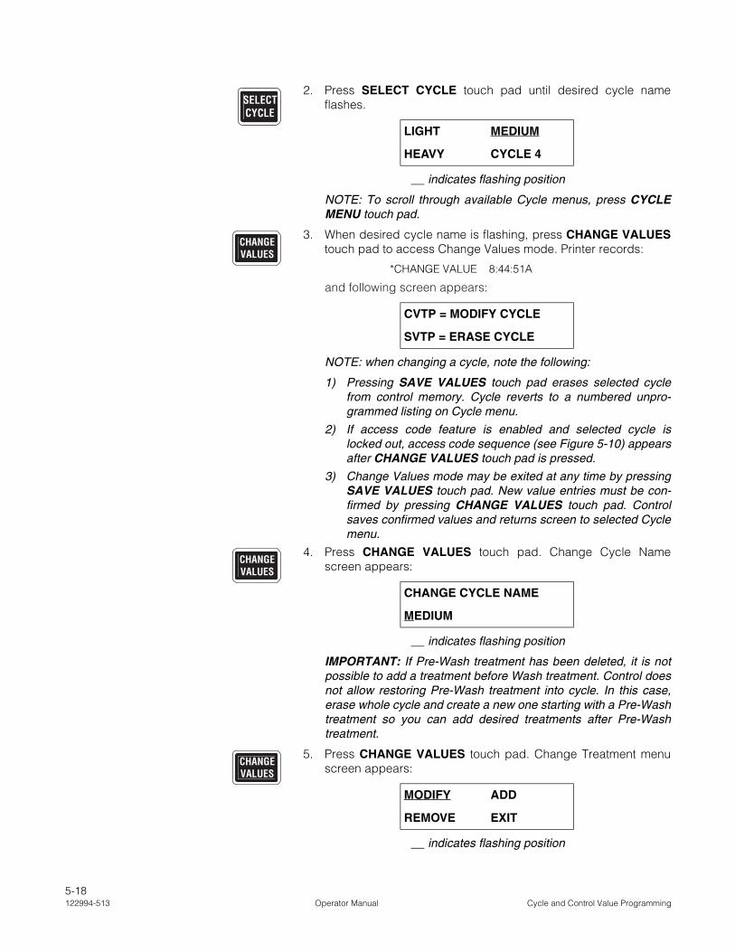
2. Press SELECT CYCLE touch pad until desired cycle nameflashes.
__ indicates flashing position
NOTE: To scroll through available Cycle menus, press CYCLEMENU touch pad.
3. When desired cycle name is flashing, press CHANGE VALUEStouch pad to access Change Values mode. Printer records:
*CHANGE VALUE 8:44:51A
and following screen appears:
NOTE: when changing a cycle, note the following:
1) Pressing SAVE VALUES touch pad erases selected cyclefrom control memory. Cycle reverts to a numbered unpro-grammed listing on Cycle menu.
2) If access code feature is enabled and selected cycle islocked out, access code sequence (see Figure 5-10) appearsafter CHANGE VALUES touch pad is pressed.
3) Change Values mode may be exited at any time by pressingSAVE VALUES touch pad. New value entries must be con-firmed by pressing CHANGE VALUES touch pad. Controlsaves confirmed values and returns screen to selected Cyclemenu.
4. Press CHANGE VALUES touch pad. Change Cycle Namescreen appears:
__ indicates flashing position
IMPORTANT: If Pre-Wash treatment has been deleted, it is notpossible to add a treatment before Wash treatment. Control doesnot allow restoring Pre-Wash treatment into cycle. In this case,erase whole cycle and create a new one starting with a Pre-Washtreatment so you can add desired treatments after Pre-Washtreatment.
5. Press CHANGE VALUES touch pad. Change Treatment menuscreen appears:
__ indicates flashing position
LIGHT MEDIUM
HEAVY CYCLE 4
CVTP = MODIFY CYCLE
SVTP = ERASE CYCLE
CHANGE CYCLE NAME
MEDIUM
MODIFY ADD
REMOVE EXIT
SELECTCYCLE
CHANGEVALUES
CHANGEVALUES
CHANGEVALUES
5-18122994-513 Operator Manual Cycle and Control Value Programming

6. Press CURSOR arrows (left or right) or VALUE arrows (up ordown) to select REMOVE function.
__ indicates flashing position
7. Press CHANGE VALUES touch pad to confirm REMOVE func-tion selection. Remove Treatment screen appears:
__ indicates flashing position
To select treatment to be removed, press VALUE arrows (up ordown) to scroll through treatments until desired treatment nameis flashing.
8. Press CHANGE VALUES touch pad to confirm and removeselected treatment from programmed cycle. Change Valuesmenu screen appears:
__ indicates flashing position
9. At this point, operator has option to either continue in ChangeValues mode, or to save values and exit Change Values mode.
• To exit Change Values mode, press SAVE VALUES touchpad. Control saves changed values and returns screen toselected Cycle menu.
• To continue in Change Values mode, press CURSORarrows (left or right) or VALUE arrows (up or down) toselect function. Press CHANGE VALUES to confirm selec-tion and initiate the function program.
MODIFY ADD
REMOVE EXIT
REMOVE TREATMENT
PRE-WASH 1
MODIFY ADD
REMOVE EXIT
CURSOR VALUE
CHANGEVALUES
VALUE
CHANGEVALUES
SAVEVALUES
CHANGEVALUES
CURSOR VALUE
5-19Cycle and Control Value Programming Operator Manual 122994-513
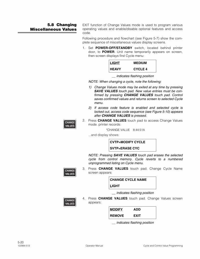
5.8 ChangingMiscellaneous Values
EXIT function of Change Values mode is used to program variousoperating values and enable/disable optional features and accesscode.
Following procedure and flowchart (see Figure 5-7) show the com-plete sequence of miscellaneous values display screens.
1. Set POWER-OFF/STANDBY switch, located behind printerdoor, to POWER. Unit name temporarily appears on screen,then screen displays first Cycle menu:
__ indicates flashing position
NOTE: When changing a cycle, note the following:
1) Change Values mode may be exited at any time by pressingSAVE VALUES touch pad. New value entries must be con-firmed by pressing CHANGE VALUES touch pad. Controlsaves confirmed values and returns screen to selected Cyclemenu.
2) If access code feature is enabled and selected cycle islocked out, access code sequence (see Figure 5-10) appearsafter CHANGE VALUES is pressed.
2. Press CHANGE VALUES touch pad to access Change Valuesmode. printer records:
*CHANGE VALUE 8:44:51A
...and display shows:
NOTE: Pressing SAVE VALUES touch pad erases the selectedcycle from control memory. Cycle reverts to a numberedunprogrammed listing on Cycle menu.
3. Press CHANGE VALUES touch pad. Change Cycle Namescreen appears:
__ indicates flashing position
4. Press CHANGE VALUES touch pad. Change Values screenappears:
__ indicates flashing position
LIGHT MEDIUM
HEAVY CYCLE 4
CVTP=MODIFY CYCLE
SVTP=ERASE CYC
CHANGE CYCLE NAME
LIGHT
MODIFY ADD
REMOVE EXIT
CHANGEVALUES
CHANGEVALUES
CHANGEVALUES
5-20122994-513 Operator Manual Cycle and Control Value Programming

STATUS
STATUS
STATUS
STATUS
SAVEVALUES
ConfirmSelection
ConfirmSelection
SAVEVALUES
ConfirmSelection
STATUS
ConfirmSelection
STATUS
ConfirmSelection
SAVEVALUES
Press CURSORCURSORCURSORCURSORCURSOR andVALUEVALUEVALUEVALUEVALUE arrows totoggle between values.
Press CURSORCURSORCURSORCURSORCURSOR andVALUEVALUEVALUEVALUEVALUE arrows totoggle between values.
Press CURSORCURSORCURSORCURSORCURSOR andVALUEVALUEVALUEVALUEVALUE arrows totoggle between values.
STATUS
STATUS
STATUS
To ModifyCycle
ConfirmSelection
ConfirmSelection
STATUS
STATUS
Press CYCLECYCLECYCLECYCLECYCLEMENUMENUMENUMENUMENU to scrollcycle menus andSELECT CYCLESELECT CYCLESELECT CYCLESELECT CYCLESELECT CYCLE toselect cycle.
ConfirmSelection
Press VALUEVALUEVALUEVALUEVALUEarrows to togglebetween YES andNO.
STATUS
STATUS
ConfirmSelection
SAVEVALUES
POWER
OFF
STANDBY
SAVEVALUES
SAVEVALUES
STATUS
Press VALUEVALUEVALUEVALUEVALUEarrows to togglebetween YES andNO.
ConfirmSelection
SAVEVALUES
Press VALUEVALUEVALUEVALUEVALUEarrows totogglebetween YESand NO.
Press VALUEVALUEVALUEVALUEVALUEarrows totogglebetween YESand NO.
Press CURSORCURSORCURSORCURSORCURSOR andVALUEVALUEVALUEVALUEVALUE arrows totoggle betweenvalues.
To EraseCycle
SAVEVALUES
+CHANGEVALUES
CHANGEVALUES
CHANGEVALUES
... continued
ConfirmSelection
ConfirmSelection
CHANGEVALUES
ACCESS CODENO
YES NO
CHANGEVALUES
CHANGE ACCESS CODE?NEW CODE = 0000
CHANGEVALUES
CYCLES TO LOCKOUT=00
CHANGEVALUES
WATER SAVER ENABLEDNO
YES NO
CHANGEVALUES
YES generatesprintout of cyclevalues forselected cycleonly.
* RELIANCE * * MODEL 400 *
LIGHT MEDIUMHEAVY CYCLE 4
CHANGEVALUES
CVTP=MODIFY CYCLESVTP=ERASE CYCLE
CHANGEVALUES
CHANGE CYCLE NAME LIGHT
CHANGEVALUES
MODIFY CREATEREMOVE EXIT
CHANGEVALUES
START WITH FRESH H2OYES
YES NO
CHANGEVALUES
PRINT CYCLE VALUESNO
YES NO
CHANGEVALUES
CHANGE MISC. VALUES?NO
YES NO
CHANGEVALUES
PRINTER ENABLED?YES
YES NO
CHANGEVALUES
DATE 00/00/00TIME 00:00:00 AM
STATUS
LIGHT MEDIUMHEAVY CYCLE 4
SAVEVALUES
SAVEVALUES
Figure 5-7. Change Values Mode – Changing Miscellaneous Values
5-21Cycle and Control Value Programming Operator Manual 122994-513

5. Press CURSOR arrows (left or right) or VALUE arrows (up ordown) to select EXIT function:
__ indicates flashing position
6. Press CHANGE VALUES touch pad to confirm selection. ModifyTreatment screen appears:
__ indicates flashing position
7. Press VALUE arrows (up or down) to toggle between YES andNO. Display shows:
__ indicates flashing position
8. Press VALUE arrows (up or down) to toggle between YES andNO.
9. Press CHANGE VALUES touch pad to confirm rate entry. PrintCycle Values screen appears:
__ indicates flashing position
NOTE: If printer is disabled, display goes directly to ChangeMiscellaneous Values screen.
Press VALUE arrows (up or down) to toggle between YES andNO. Selecting YES generates a printout of cycle values for theselected cycle. Selecting NO bypasses printing.
NOTE: Pressing SAVE VALUES and then CHANGE VALUEStouch pads exit Change Values mode and display returns to firstCycle menu.
10. Press CHANGE VALUES touch pad to confirm answer selec-tion. Display shows:
__ indicates flashing position
Press VALUE arrows (up or down) to toggle between YES andNO. Selecting NO exits Change Values mode. Selecting YESallows operator to change miscellaneous operating values.
MODIFY ADD
REMOVE EXIT
START WITH FRESH H2O
NO
CHANGE INJECT. RATES
NO
PRINT CYCLE VALUES
NO
CHANGE MISC. VALUES?
NO
CURSOR VALUE
CHANGEVALUES
VALUE
VALUE
CHANGEVALUES
VALUE
CHANGEVALUES
VALUE
5-22122994-513 Operator Manual Cycle and Control Value Programming

NOTE: If NO is selected, pressing SAVE VALUES or CHANGEVALUES touch pad exits Change Values mode and displayreturns to first Cycle menu.
11. Press CHANGE VALUES touch pad to confirm answer selec-tion. Printer Enable/Disable screen appears:
__ indicates flashing position
Press VALUE arrows (up or down) to toggle between YES andNO. Selecting YES automatically generates a printout duringcycle operation. Selecting NO disables printer.
NOTE: If NO is selected, pressing SAVE VALUES or CHANGEVALUES touch pad exits Change Values mode and displayreturns to first Cycle menu.
12. Press CHANGE VALUES touch pad to confirm answer selec-tion. Date and Time value screen appears:
__ indicates flashing position
To enter correct date and time, press CURSOR arrows (left orright) to select position and VALUE arrows (up or down) toselect desired number (0-9). Date is input as two-digit numericalvalues for Year/Month/Day. Time is input as Hours/Minutes/Seconds and AM/PM.
13. Press CHANGE VALUES touch pad to confirm date and timeentry. Access code screen appears:
__ indicates flashing position
NOTE: If access code is already enabled, access code sequenceis displayed (see Figure 5-10).
Press VALUE arrows (up or down) to toggle between YES andNO. Selecting YES enables access code and cycle lockoutfeatures. Selecting NO disables access code feature.
14. Press CHANGE VALUES touch pad to confirm answer selec-tion. If NO is selected, display exits to Change Value mode. IfYES is selected, new Access Code screen appears:
__ indicates flashing position
PRINTER ENABLED?
YES
DATE 00/00/00
TIME 00:00:00 AM
ACCESS CODE
YES
CHANGE ACCESS CODE?
NEW CODE = 0000
CHANGEVALUES
VALUE
CHANGEVALUES
CURSOR VALUE
CHANGEVALUES
VALUE
CHANGEVALUES
5-23Cycle and Control Value Programming Operator Manual 122994-513

To enter desired access code, press CURSOR arrows (left orright) to select position and VALUE arrows (up or down) toselect desired number (0-9). Access code is input as a four-digitnumber from 0000 to 9999.
NOTE: If no access code is entered, 0000 is automaticallyprogrammed as access code.
15. Press CHANGE VALUES touch pad to confirm value entry.Cycle Lockout screen appears:
__ indicates flashing position
To enter locked-out cycles, press CURSOR arrows (left or right)to select position and VALUE arrows (up or down) to selectdesired number (0-9). Cycles to lockout is input as a two-character number within range of 00-11.
NOTE: Cycles are locked out in sequential order. If one cycle islocked out (01), only Cycle 1 requires an operator to enter accesscode prior to making cycle changes. If four cycles are locked out(04), Cycles 1 through 4 require an access code and Cycles 5through 10 remain accessible for change by any operator (noaccess code required).
16. Press CHANGE VALUES touch pad to confirm value entry. Dis-play shows:
__ indicates flashing position
17. Press VALUE arrows (up or down) to toggle between YES andNO. If YES is selected, water is saved for all cycles processed.
18. Press CHANGE VALUES touch pad to return to main Cyclemenu.
CYCLES TO LOCKOUT = 00
WATER SAVER ENABLED
YES
CURSOR VALUE
CHANGEVALUES
CURSOR VALUE
CHANGEVALUES
VALUE
CHANGEVALUES
5-24122994-513 Operator Manual Cycle and Control Value Programming

5.9 Select InjectionTime Rate
5.9.1 General See Figure 5-8.
1. Set POWER-OFF/STANDBY switch, located behind printerdoor, to POWER. Unit name temporarily appears on screen,then screen displays first Cycle menu:
__ indicates flashing position
NOTE: When changing a cycle, note the following:
1) Change Values mode may be exited at any time by pressingSAVE VALUES touch pad. New value entries must be con-firmed by pressing CHANGE VALUES touch pad. Controlsaves confirmed values and returns screen to selected Cyclemenu.
2) If access code feature is enabled and selected cycle islocked out, access code sequence (see Figure 5-10) appearsafter CHANGE VALUES touch pad is pressed.
2. Press CHANGE VALUES touch pad to access Change Valuesmode. Printer records:
*CHANGE VALUE 8:44:51A
and display shows:
NOTE: Pressing SAVE VALUES touch pad erases selectedcycle from control memory. Cycle reverts to a numberedunprogrammed listing on Cycle menu.
3. Press CHANGE VALUES touch pad. Change Values screenappears:
__ indicates flashing position
4. Press CHANGE VALUES touch pad. Change Cycle Namescreen appears:
__ indicates flashing position
LIGHT MEDIUM
HEAVY CYCLE 4
CVTP=MODIFY CYCLE
SVTP=ERASE CYCLE
MODIFY ADD
REMOVE EXIT
CHANGE CYCLE NAME
LIGHT
CHANGEVALUES
CHANGEVALUES
CHANGEVALUES
5-25Cycle and Control Value Programming Operator Manual 122994-513

STATUS
STATUS
STATUS
ConfirmSelection
ConfirmSelection
STATUS
STATUS
Press CYCLECYCLECYCLECYCLECYCLEMENUMENUMENUMENUMENU to scrollcycle menus andSELECT CYCLESELECT CYCLESELECT CYCLESELECT CYCLESELECT CYCLE toselect cycle.
ConfirmSelection
SAVEVALUES
SAVEVALUES
SAVEVALUES
Press CURSORCURSORCURSORCURSORCURSOR andVALUEVALUEVALUEVALUEVALUE arrows totoggle betweenvalues.
To EraseCycle
STATUS
STATUS
STATUS
STATUS
STATUS
STATUS
LIGHT MEDIUMHEAVY CYCLE 4
CHANGEVALUES
CVTP=MODIFY CYCLESVTP=ERASE CYCLE
CHANGEVALUES
MODIFY ADDREMOVE EXIT
CHANGE VALUES
CHANGE CYCLE NAMELIGHT
CHANGEVALUES
MODIFY ADDREMOVE EXIT
CHANGEVALUES
MODIFY TREATMENTPREWASH
CHANGEVALUES
SELECT WATER TEMP.HOT HEATED
CHANGEVALUES
PUMP 1 WASH 102:00 TMP=150.0F
CHANGEVALUES
DETERGETN TO INJECT?PUMP 1
CHANGEVALUES
PUMP 1INJECT. TIME =00:45
CHANGEVALUES
MODIFY ADDREMOVE EXIT
SAVE VALUES
ConfirmSelection
SAVEVALUES
ConfirmSelection
ConfirmSelection
ConfirmSelection
ConfirmSelection
ConfirmSelection
Press CURSORCURSORCURSORCURSORCURSOR andVALUEVALUEVALUEVALUEVALUE arrows totoggle betweenvalues.
Press CURSORCURSORCURSORCURSORCURSOR andVALUEVALUEVALUEVALUEVALUE arrows totoggle betweenvalues.
Press CURSORCURSORCURSORCURSORCURSOR andVALUEVALUEVALUEVALUEVALUE arrows totoggle betweenvalues.
Press CURSORCURSORCURSORCURSORCURSOR andVALUEVALUEVALUEVALUEVALUE arrows totoggle betweenvalues.
Press CURSORCURSORCURSORCURSORCURSOR andVALUEVALUEVALUEVALUEVALUE arrows totoggle betweenvalues.
ConfirmSelection
Figure 5-8. Change Values Mode – Select Injection Time Rate
5-26122994-513 Operator Manual Cycle and Control Value Programming

5. Press CHANGE VALUES touch pad. Change Values screenappears:
__ indicates flashing position
6. Press CHANGE VALUES touch pad. Modify Treatment screenappears:
__ indicates flashing position
Press VALUE arrows (up or down) to select WASH 1.
7. Press CHANGE VALUES touch pad. Select Water Temperaturescreen appears:
__ indicates flashing position
8. Press CHANGE VALUES touch pad. Pump Selection screenappears:
__ indicates flashing position
9. Press CHANGE VALUES touch pad. Detergent to Inject screenappears:
10. Press CHANGE VALUES touch pad. Select Injection Timescreen appears:
To enter pump injection time, press VALUE arrows (up or down)to select desired time. Injection time is input in seconds with arange of 00:20 to 03:00 minutes (see Table 5-1, CycleDescription Chart; contact STERIS or have a qualified servicetechnician refer to SECTION 4 in Maintenance Manual[P764330-580]).
MODIFY ADD
REMOVE EXIT
MODIFY TREATMENT
PREWASH
SELECT WATER TEMP
HOT HEATED
PUMP 1 WASH 1
02:00 TMP = 150.0F
DETERGENT TO INJECT?
PUMP1
PUMP 1
INJECT. TIME = 00:45
CHANGEVALUES
CHANGEVALUES
VALUE
CHANGEVALUES
CHANGEVALUES
CHANGEVALUES
CHANGEVALUES
VALUE
5-27Cycle and Control Value Programming Operator Manual 122994-513

NOTE: When changing a cycle, note the following:
1) Injection rate is displayed in mL/L.
2) At low speed, the sump capacity is: 12.6 gal. (47.7 L). At highspeed, the sump capacity is increased by 1.5 gal. (5.7 L).
3) Factory setting for chemical injection is 45 seconds at lowspeed. Control automatically adjusts chemical injection timeat high speed.
4) Injection time of 45 seconds equals approximately to 1/2 oz/gal(4.0 mL/L).
11. Press CHANGE VALUES to return to confirm.
12. Press SAVE VALUES touch pad to return to main Cycle menu.
CHANGEVALUES
SAVEVALUES
5-28122994-513 Operator Manual Cycle and Control Value Programming
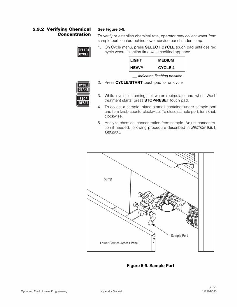
5.9.2 Verifying ChemicalConcentration
See Figure 5-9.
To verify or establish chemical rate, operator may collect water fromsample port located behind lower service panel under sump.
1. On Cycle menu, press SELECT CYCLE touch pad until desiredcycle where injection time was modified appears:
__ indicates flashing position
2. Press CYCLE/START touch pad to run cycle.
3. While cycle is running, let water recirculate and when Washtreatment starts, press STOP/RESET touch pad.
4. To collect a sample, place a small container under sample portand turn knob counterclockwise. To close sample port, turn knobclockwise.
5. Analyze chemical concentration from sample. Adjust concentra-tion if needed, following procedure described in SECTION 5.9.1,GENERAL.
LIGHT MEDIUM
HEAVY CYCLE 4
SELECTCYCLE
CYCLESTART
STOPRESET
REF.: # 920-012-111
Figure 5-9. Sample Port
Sample Port
Lower Service Access Panel
Sump
5-29Cycle and Control Value Programming Operator Manual 122994-513

5.10 ProgrammingValues With Access
Code Enabled
Access code feature is used to prevent unauthorized changes toparameters of designated cycles and/or operating values. With thisfeature, access to cycle values may be selectively limited to autho-rized operators, depending on security needs of washer environ-ment. When access code is enabled, only authorized operators canchange operating values regardless of locked out cycles.
The following procedure and flowchart (see Figure 5-10) provideexamples of how to access Change Values mode when the accesscode feature is enabled.
1. Set POWER/OFF-STANDBY switch, located behind printerdoor, to POWER. Unit name temporarily appears on screen,then screen displays first Cycle menu:
__ indicates flashing position
NOTE: To scroll through available Cycle menus, press CYCLEMENU touch pad.
2. Press CHANGE VALUES touch pad to confirm cycle selection.Display shows:
__ indicates flashing position
Press CURSOR arrows (left or right) to toggle between YES andNO.
3. Press CHANGE VALUES touch pad to confirm answer selec-tion. If YES, following screen appears:
__ indicates flashing position
To enter correct access code, press CURSOR arrows (left orright) to select position and VALUE arrows (up or down) toselect desired number (0-9). Access code is entered as a four-digit number from 0000 to 9999.
NOTE: If incorrect access code is entered, display showsACCESS DENIED!, then display automatically returns to firstCycle menu.
4. Once correct access code is entered, press CHANGE VALUEStouch pad to confirm and access Change Values mode. See Fig-ures 5-3 to 5-8 for flowcharts of available programming func-tions.
LIGHT MEDIUM
HEAVY CYCLE 4
ACCESS CODE KNOWN?
NO
ENTER OPERATOR
ACCESS CODE: 0000
STATUS
ConfirmSelection
STATUS
STATUS
POWER
OFF
STANDBY
Press SELECTSELECTSELECTSELECTSELECTCYCLECYCLECYCLECYCLECYCLE toselect cycle tomodify.
ConfirmSelection
STATUS
ConfirmSelection
Press VALUEVALUEVALUEVALUEVALUEarrows totogglebetween YESand NO.
* RELIANCE * * MODEL 400 *
LIGHT MEDIUMHEAVY CYCLE 4
CHANGEVALUES
ACCESS CODE KNOWN?NO
YES NO
CHANGEVALUES
ENTER OPERATORACCESS CODE = 0000
CHANGEVALUES
OPERATOR MAYNOW USE ANY
CHANGE VALUES MODEPROGRAM FUNCTION
(See Figures 5-3 to 5-8)
Figure 5-10. Change Values Mode – Programming With
Access Code Enabled
CHANGEVALUES
5-30122994-513 Operator Manual Cycle and Control Value Programming

5.11 Review CycleValues
Each cycle program may be reviewed by accessing Review modewhen a cycle is not in progress. Review mode allows operator toview current settings of each programmable treatment value for thespecific cycle selected.
1. Press CYCLE MENU touch pad until desired Cycle menuappears on screen:
__ indicates flashing position
2. Press SELECT CYCLE touch pad until desired cycle nameflashes:
__ indicates flashing position
3. Press REVIEW CYCLE touch pad to access Review mode andview first treatment value programmed for selected cycle:
__ indicates flashing position
4. Continue to press REVIEW CYCLE touch pad to sequentiallyview each treatment value programmed for selected cycle (forexample, value for optional pure water thank shown):
__ indicates flashing position
5. Press REVIEW CYCLE touch pad until printout messageappears on screen:
6. To generate a printout of viewed cycle treatments and values,press REVIEW CYCLE touch pad. Control exits Review modeand display screen returns to selected Cycle menu:
__ indicates flashing position
LIGHT MEDIUM
HEAVY CYCLE 4
LIGHT MEDIUM
HEAVY CYCLE 4
PRE-WASH1
RECIRC. TIME = XX:XX
PURE W. 1
NON-REC. TIME = 00:10
PRINT CYCLE VALUES?
REVIEW = YES STOP = NO
LIGHT MEDIUM
HEAVY CYCLE 4
CYCLEMENU
SELECTCYCLE
REVIEWCYCLE
REVIEWCYCLE
REVIEWCYCLE
REVIEWCYCLE
5-31Cycle and Control Value Programming Operator Manual 122994-513

and printer records:
===========================
= CYCLE PROGRAM REVIEW =
= CYCLE - MEDIUM =
===========================
REVIEW TIME 8:46:38A
REVIEW DATE 99/03/09
UNIT NUMBER 0000000000
PRE-WASH1
RECIRC. TIME = 1:00
WATER TEMP. = COLD
PUMP1 WASH1
RECIRC. TIME = 4:00
HEATED AT = 150.0F
RINSE 1
RECIRC. TIME = 1:00
WATER TEMP. = HOT
7. To bypass printout option, press STOP/RESET touch pad. Con-trol exits Review mode and display screen returns to selectedCycle menu:
__ indicates flashing position
LIGHT MEDIUM
HEAVY CYCLE 4
STOPRESET
5-32122994-513 Operator Manual Cycle and Control Value Programming
6ROUTINE MAINTENANCE
6.1 General The sample preventive maintenance guide (Table 6-1) included inthis section should be used as a guideline for determining the fre-quency of maintenance. This proves useful in helping ensure propermaintenance of your glassware washer.
Maintenance procedures described in this section must be per-formed as required at the suggested frequency. Indicated frequen-cies are minimums and can be changed if glassware washer usewarrants.
If a problem occurs, refer to SECTION 7, TROUBLESHOOTING.
Refer to the Maintenance Manual (P764330-580) for completereplacement parts list.
IMPORTANT: A listing of the Safety Precautions to be observed when operating and servicing thisglassware washer can be found in SECTION 1 of this manual. Do not operate the equipment until you havebecome familiar with this information.
WARNING–PERSONAL INJURYAND/OR EQUIPMENT DAMAGEHAZARD:
• Regularly scheduled preven-tive maintenance is requiredfor safe and reliable opera-tion of this equipment. Con-tact STERIS to schedulepreventive maintenance.
• Repairs and adjustmentsto this equipment must bemade only by STERIS orSTERIS-trained servicepersonnel. Repairs andadjustments performed byunqualified personnel orinstallation of unautho-rized parts could causepersonal injury, result inimproper equipment per-formance, void the war-ranty or result in costlydamage. Contact STERISregarding service options.
6-1Routine Maintenance Operator Manual 122994-513

6.2 PreventiveMaintenance
The following guide should be followed to properly maintain theglassware washer. Some procedures should be carried out only byqualified service technicians. These procedures are noted by a star(*). Contact STERIS when service is required.
NOTE: Preventive Maintenance is not covered under warranty.
Table 6-1. Preventive Maintenance Guide
Recommended frequency of inspection is indicated in the right column. Usage andutility conditions may require more or less frequent inspections.
Suggested Frequency
1.0 PREPARATION FOR PREVENTIVE MAINTENANCE
1.1 Discuss equipment operation with department personnel. 6 X/year
1.2 Inspect printouts for signs of trouble. 6 X/year
1.3When required by procedure, shut off all building services and drain all lines.Always follow local occupational health and safety regulations, as well as electricand plumbing codes.
As required
2.0 EAGLE® 3000 STAGE 3 CONTROL SYSTEM
2.1 Inspect printer for proper operation. 6 X/year
2.2 Inspect for proper operation of touch panel. Verify all touch pads If faulty, call STERIS.* 6 X/year
2.3 Verify proper date and time are displayed; if not, reset. 6 X/year
2.4 Verify paper take up is working properly. 6 X/year
2.5 Verify printout for darkness, missing dots, etc. 3 X/year
2.6 Verify buzzer on control PC board is functioning properly. 6 X/year
3.0 DOOR ASSEMBLY
3.1 Inspect door for ease of operation while a cycle is in progress. If faulty, call STERIS.* 3 X/year
3.2 Inspect door cable and pulleys. Replace if necessary.* 6 X/year
3.3 Verify condition and operation of door limit switch.* 6 X/year
3.4 Verify condition and operation of obstruction proximity sensor on top of door. * 6 X/year
3.5 Replace door limit switch bottom spring.* 1 X/year
4.0 CHAMBER COMPONENTS
4.1Inspect rotary spray arm assemblies for free movement and no clogged holes (seeSECTION 6.4).
6 X/year
4.2Verify bushings are in good condition and properly installed over and under rotaryspray arm hub (see SECTION 6.4).
3 X/year
4.3 Clean debris screens in wash chamber (see SECTION 6.3). 6 X/year
4.4Remove hard water deposits from interior of chamber (use DESCALER cycle; seeSECTION 6.5.1).
6 X/year
*Contact STERIS for this service. Preventive Maintenance is not covered under warranty.
6-2122994-513 Operator Manual Routine Maintenance

4.5 Verify proper water level and temperature.* 3 X/year
4.6 Verify piping system for leaks. Repair if necessary.* 6 X/year
4.7 Verify condition of sliding guides. Replace if necessary.* 3 X/year
5.0 SUPPLY-LINE STRAINERS
Inspect strainers for debris. Clean as necessary (see SECTION 6.5.2). 6 X/year
6.0 CHEMICALS AND INJECTION PUMPS
6.1 Verify suction tube is not clogged, cracked or distorted. If damaged, call STERIS.* 6 X/year
6.2 Inspect and lubricate squeeze tubes. Replace if necessary (see SECTION 6.7). 6 X/year
6.3 Verify amount of chemical product injected. Adjust if necessary. 3 X/year
6.4 Lubricate pump roller (see SECTION 6.7). 6 X/year
7.0 COMPRESSOR
Verify intake filter and mufflers. Change if necessary.* 2 X/year
8.0 PROTECTIVE GROUND TERMINAL*
Verify protective conductor at equipment terminal and verify if connection is wellsecured inside terminal with proper torque equipment. Torque requirement forsupply conductor terminals for steam heated units (L1-L2-L3- N) is: 7.1 - 8.9 lb/in(0.8 -1.0 N•m) and for electric heated units (L1-L2-L3- N) is: 7.1 - 8.9 lb/in (0.8 -1.0 N•m); for steam- and electric-heated units, protective conductor terminal is:20 lb/in (2.2 N•m).*
1 X/year
9.0 FINAL TEST
9.1Clean dirt and lint from components. Verify all wiring, terminals and socket connec-tions for damage or fraying.
6 X/year
9.2 Verify glassware washer has proper labels (caution, warning, etc.). 6 X/year
9.3 Install any panel or cover removed during inspection. 6 X/year
9.4 Test glassware washer operation. 6 X/year
Table 6-1. Preventive Maintenance Guide (Cont’d)
Recommended frequency of inspection is indicated in the right column. Usage andutility conditions may require more or less frequent inspections.
Suggested Frequency
*Contact STERIS for this service. Preventive Maintenance is not covered under warranty.
6-3Routine Maintenance Operator Manual 122994-513

6.3 Daily Cleaning 1. After last cycle of day, allow unit to cool. Then, remove and cleandebris screens in bottom of wash chamber and suction filter atbottom of sump. Always clean screens while they are still wet,before foreign matter dries.
2. Remove riser valve and inspect for debris. Brush and rinseunder tap water if necessary.
6.4 Weekly Cleaning On a weekly basis, perform the following routine cleaning proce-dures:
1. Clean washer exterior as follows: Using a general cleaner forgeneral stains, a stainless-steel stain remover for stubborn stainsand a stainless-steel polish to keep equipment looking like new.
a. Using a damp cloth or sponge, apply cleaner in a back-and-forth motion, rubbing in same direction as surface grain.
b. Thoroughly wipe off cleaner.
c. Polish surface with a clean, dry, lint-free cloth.
2. Wash chamber interior with a moderately alkaline detergent solu-tion. Rinse with tap water and dry with a lint-free cloth.
NOTE: If interior is stained, use a general cleaner to removegeneral stains, or a stainless-steel stain remover for stubbornstains. Using a damp cloth or sponge, apply cleaner in a back-and-forth motion, rubbing in same direction as surface grain.Thoroughly wipe off cleaner and polish with a clean, dry, lint-freecloth.
3. Clean wash chamber rotary spray arm assemblies as follows:
a. Remove rotary spray holder from top of wash chamber.
NOTE: Before removing rotary spray holder, note the following:
1) There are two loose bushings, one under and one over rotaryspray hub. When lowering rotary spray assembly, bushingsfall. Ensure to hold on to bushings while removing rotaryspray assembly.
2) Do not remove spray arms from rotary spray arm hub.
b. Rinse each spray arm assembly under running water toclean out sediment.
c. Use a fine wire (approximately wire gauge of a paper clip) toclean sediment from spray nozzles. Rinse under running water.
d. Place bushings on rotary spray arm hub and reattach sprayarm assembly to top of wash chamber.
WARNING–SLIPPING HAZARD:To prevent slips, keep floorsdry. Promptly clean up anyspills or drippage. For spillsor drippage of detergents orother chemicals, follow safetyprecautions and handling pro-cedures set forth on deter-gent or chemical label and/orMaterial Safety Data Sheet(MSDS).
WARNING–SLIPPING HAZARD:To prevent slips, keep floorsdry. Promptly clean up anyspills or drippage. For spillsor drippage of detergents orother chemicals, follow safetyprecautions and handling pro-cedures set forth on deter-gent or chemical label and/orMaterial Safety Data Sheet(MSDS).
CAUTION – POSSIBLE EQUIP-MENT DAMAGE: Use nonabra-sive cleaners when cleaningunit. Follow directions on con-tainers and rub in a back-and-forth motion (in same directionas surface grain). Abrasivecleaners will damage stain-less steel. Cleaners rubbed ina circular motion or appliedwith a wire brush or steel woolon door and chamber assem-blies can be harmful to stain-less steel. Do not use thesecleaners on painted surfaces.
6-4122994-513 Operator Manual Routine Maintenance

4. Clean rotary spray arms on accessories in same way as cham-ber spray arms.
6.5 Monthly Cleaning
6.5.1 Remove Hard WaterDeposits
NOTE: Depending on hardness of water being used, it may be neces-sary to remove hard water deposits more often. Remove depositsfrom chamber and accessories whenever deposits become visible.
Remove hard water deposits from chamber and loading accessoriesas follows, using DESCALER cycle especially designed for this pur-pose:
1. Place empty rack in wash chamber over manifold connector.
2. Press CYCLE MENU touch pad to scroll to appropriate Cyclemenu.
3. Press SELECT CYCLE touch pad to select DESCALER cycle.Display shows:
__ indicates flashing position
4. Press CYCLE/START touch pad to confirm DESCALER cycleselection. Display shows:
5. Press CYCLE/START touch pad to start DESCALER cycle. Dis-play shows:
NOTE: If CYCLE/START touch pad is not pressed within fiveseconds, display returns to main Cycle menu.
6. Open chamber door and pour 25 oz (740 mL) of descaling liquidinto wash chamber. Display shows:
7. Close door. Press CYCLE/START touch pad to start DESCALERcycle.
8. At completion of cycle, open door and allow unit to air dry.
9. Verify debris screens in bottom of sump for debris. If debris ispresent, rinse filters under running water to clean.
CYCLE 9 CYCLE 10
DESCALER PRIME
PRESS START TO
PROCESS - DESCALER
OPEN LOAD DOOR AND
ADD DETERGENT
PLEASE CLOSE DOOR
TO START DESCALER
WARNING – CHEMICAL BURNAND/OR EYE INJURY HAZARD:
• Detergents are caustic andcan cause adverse effects toexposed tissues. Do not getin eyes, on skin or attempt toswallow. Read and follow theprecautions and instructionson the detergent label and inthe Material Safety DataSheet (MSDS) prior to han-dling the detergent, refillingthe detergent container orservicing the detergent injec-tion pump and lines. Wearappropriate Personal Protec-tive Equipment (PPE) when-ever handling the detergentor servicing the detergentinjection pump and lines.
• Wear appropriate PersonalProtective Equipment (PPE)when using a descaling prod-uct. Avoid contact with theeyes or skin. If a descalingproduct spills or splashes onyou, flush the affected areawith water for 15 minutes. Ifswallowed, DO NOT inducevomiting. Administer an alkaliwith plenty of water. Seekmedical attention immedi-ately.
CAUTION – POSSIBLE EQUIP-MENT DAMAGE: When choos-ing a detergent, select one witha low-chloride content. Deter-gents with a high-chloride con-tent must not be used, as suchdetergents may harm stainlesssteel.
6-5Routine Maintenance Operator Manual 122994-513
6.5.2 Clean Building Supply-Line Strainers
NOTE: Piping tools are required. Contact facility maintenance techni-cian for this procedure.
Clean building supply-line strainers as follows:
1. Position building electrical disconnect switch (circuit breaker) toOFF position.
2. Close building supply-lines: hot water, cold water (if optionapplies), pure water and steam (if option applies).
3. Position power switch (located under load side control) to OFF.
4. Unlock and open lower access doors.
5. Remove and clean strainers under running water.
6. Reinstall strainers.
7. Close and lock lower access doors.
8. Open building supply lines.
9. Restore power to unit.
6.6 ChemicalContainer
Replacement
NOTE: For cleaning and descaling products, note the following:
1) Contact STERIS for information on specific cleaning and descal-ing products recommended for use with this equipment.
2) Always use a non-foaming detergent for effective cleaning andproper pump operation. Detergents with a high chloride contentshould not be used, as chlorides are harmful to stainless steel.Refer to detergent specifications in SECTION 2.3, DETERGENTS
AND CHEMICAL ADDITIVES SPECIFICATIONS, and follow detergentmanufacturer’s recommendations for amount of detergent to beused.
1. If detergent is low or has run out, install a new container.
2. Place low level sensor upright in container (refer to Figure 4-1).
3. Insert squeeze/suction tube into new container.
4. Refer to SECTION 4.2, PRIMING PROCEDURE, to fill tubing withdetergent.
IMPORTANT: DO NOT insert suction tube into container withoutverifying it is for the proper application (refer to SECTION 2.3,DETERGENTS AND CHEMICAL ADDITIVES SPECIFICATIONS, for details).
WARNING – BURN HAZARD:Allow piping to cool beforeinspecting and/or cleaningsupply-line strainers.
WARNING–CHEMICAL BURNAND/OR EYE INJURY HAZ-ARD: Detergents are causticand can cause adverse effectsto exposed tissues. Do not getin eyes, on skin or attempt toswallow. Read and follow theprecautions and instructions onthe detergent label and in theMaterial Safety Data Sheet(MSDS) prior to handling thedetergent, refilling the detergentcontainer or servicing the deter-gent injection pump and lines.Wear appropriate Personal Pro-tective Equipment (PPE) when-ever handling the detergent orservicing the detergent injec-tion pump and lines.
CAUTION – POSSIBLE EQUIP-MENT DAMAGE: When choos-ing a detergent, select onewith a low-chloride content.Detergents with a high-chlo-ride content must not beused, as such detergents mayharm stainless steel.
6-6122994-513 Operator Manual Routine Maintenance

6.7 Inspect andLubricate Peristaltic
Injection PumpSqueeze Tubes
Each month, lubricate and inspect injection pump squeeze tube(s)as follows:
1. Use silicone lubricant (P117950-599) to lubricate section ofsqueeze tube in contact with pump(s).
2. Verify squeeze tube(s) for any leaks or signs of wear. If neces-sary, replace tube as follows:
a. If unit is ON, position power switch to OFF.
b. Remove upper service access panel. Injection pumps arelocated on left, on load side.
c. Remove clamps and disconnect squeeze tube ends fromsuction and feed lines.
d. Remove screws attaching injection pump faceplate to injec-tion pump head. Lift faceplate away from pump head.
e. To remove squeeze tube from pump head, pull out tube byone end. Discard tube.
f. Clean all pump surfaces.
g. Insert one end of new tube into pump head and rotate rollerblock manually.
h. Liberally spread silicone lubricant (P117950-599) over rollersin roller block and all tubing surfaces in contact with pumphead.
i. Return faceplate to pump head and fasten with previouslyremoved screws.
j. Connect ends of tube to suction and feed lines. Attachclamps to both lines.
k. Reinstall upper access panel.
l. Refer to SECTION 4.2, PRIMING PROCEDURE, to fill tubing withchemical.
m. Position power switch to ON, initiate a cycle and verifysqueeze tube operation.
WARNING–CHEMICAL BURNAND/OR EYE INJURY HAZ-ARD: Detergents are causticand can cause adverse effectsto exposed tissues. Do notget in eyes, on skin or attemptto swallow. Read and followthe precautions and instruc-tions on the detergent labeland in the Material SafetyData Sheet (MSDS) prior tohandling the detergent, refill-ing the detergent container orservicing the detergent injec-tion pump and lines. Wearappropriate Personal Protec-tive Equipment (PPE) when-ever handling the detergent orservicing the detergent injec-tion pump and lines.
CAUTION – POSSIBLE EQUIP-MENT DAMAGE: Always use asilicone lubricant to lubricatesqueeze tubes. Petroleum-basedlubricants, such as Vaseline®1 orgrease, will cause squeeze tubesto melt.
1 Vaseline is a trademark of CheseboroughPond's Incorporated.
6-7Routine Maintenance Operator Manual 122994-513

6.8 Verify Power Doors Verify operation of vertical sliding doors. Verify door operatessmoothly. Refer to SECTION 7, TROUBLESHOOTING, if door does notoperate smoothly.
Verify operation of each door safety switch as follows:
1. Wearing appropriate Personal Protective Equipment (PPE),attempt to initiate a cycle with load side door open.
2. Close door and start a cycle. Wearing appropriate Personal Pro-tective Equipment (PPE), slowly open door to verify operation ofautomatic stop.
3. Repeat for unload side door.
6.9 Changing PrinterPaper Roll
See Figure 6-1.
NOTE: Do not operate printer without paper.
1. Open printer door.
2. Grasp remaining paper and pull it upward and out of printer.
3. Remove take-up spindle from its drive mechanism by pulling it toleft.
4. Remove paper roll from take-up spindle and set empty take-upspindle aside.
5. Lower platen and remove lower paper spindle by pulling itstraight forward.
6. Place new paper roll onto lower spindle with paper feedingdownward from back of paper roll.
NOTE: Verify paper roll is positioned correctly. Thermal printerdoes not print if paper roll is inserted backward. Use only STERISthermal paper (P129359-008). Damage to printer mechanismscan occur if paper of different width or thickness is used.
7. Place lower spindle (with new paper roll) back into position bypressing from front until it snaps into place.
8. Pull 4 or 5 inches (10 to 13 cm) of paper out from roll and tearcorners off end.
9. Slide tab of paper roll into printer from back (with platen still indown position) until it exits from front of printer.
10. Grasp tab of paper, pull up 10 to 12 inches (25 to 30 cm) ofpaper and feed this paper through opening in platen.
11. Insert tab of new paper roll into slot of take-up spindle and rotatespindle to secure paper in slot.
12. Raise platen back up into position and snap in place undercatch.
WARNING – BURN HAZARD:Wear appropriate Personal Pro-tective Equipment (PPE) andopen door slowly if it is neces-sary to open during a cycle. Hotwater/steam may be sprayedthrough door opening whenverifying automatic stop whilewasher is operating.
6-8122994-513 Operator Manual Routine Maintenance

13. Press take-up spindle back onto drive mechanism and allowmotor to rotate spindle to verify paper is secured to take-up roll.
14. Set POWER/OFF-STANDBY switch to OFF-STANDBY position;then, to POWER position to verify paper is correctly routed intomechanism and printer prints. Printer does not print if thermalpaper was placed on wrong side.
15. Close printer door.
Figure 6-1. Changing Printer Paper Roll
Platen
Printer Door
YES
NO
6-9Routine Maintenance Operator Manual 122994-513

6.10 Storing ThermalPaper
Thermal paper is subject to fading with time, humidity and exposureto light.
It is the manufacturer’s recommendation that thermal paper bestored in a dark place with an average ambient temperature of lessthan 77°F (25°C) and a relative humidity less than 65%. Under theseconditions, paper remains readable for at least five years. It is recom-mended that if the printed data is to be retained for periods of timelonger than five years, an additional photocopy should be made forrecord retention. In any case, a duplicate set of records should bemaintained in the files of the engineering or maintenance depart-ments.
Thermal paper begins to develop color at about 158°F (70°C), how-ever, under humid conditions, it might begin to develop at anaccelerated rate. If stored for 24 hours at 140°F (60°C), the papershows some signs of development. It also shows signs of develop-ment if stored for 24 hours at 113°F (45°C) and a relative humidity of90%.
Do not store thermal paper next to other chemically treated papers –such as pressure sensitive paper or other types of recording roundcharts – as this may cause fading in print. If thermal paper is to bestored in the same area, always ensure it and other chemicallytreated papers are kept in separate envelopes.
Thermal paper discolors when exposed to direct sunlight.
6-10122994-513 Operator Manual Routine Maintenance
7TROUBLESHOOTING
This section describes the types of washer malfunctions which mayoccur, and indicates probable causes and corrective actions.
If unable to correct problem with use of Troubleshooting Charts(Table 7-1 and Table 7-2), or if a problem occurs that is notdescribed on the charts, please call STERIS. Service charges maybe incurred. Consult your warranty for details. NEVER PERMITUNQUALIFIED PERSONS TO SERVICE THE GLASSWAREWASHER.
Table Descriptions:
Table 7-1 – Problems where NO alarm screen and printout occur.
Table 7-2 – Problems where alarm screen and/or printout occur.
IMPORTANT: A listing of the Safety Precautions to be observed when operating and servicing thisglassware washer can be found in SECTION 1 of this manual. Do not operate the equipment until you havebecome familiar with this information.
WARNING–PERSONAL INJURYAND/OR EQUIPMENT DAMAGEHAZARD: Repairs and adjust-ments to this equipment mustbe made only by STERIS orSTERIS-trained service person-nel. Repairs and adjustmentsperformed by unqualified per-sonnel or installation of unau-thorized parts could causepersonal injury, result inimproper equipment perfor-mance, void the warranty orresult in costly damage. Con-tact STERIS regarding serviceoptions.
WARNING – ELECTRIC SHOCKAND/OR BURN HAZARD:
• STERIS strongly recom-mends service be per-formed only by STERIS orSTERIS-trained service per-sonnel. Service personnelmust disconnect all utilitiesto unit before servicing. Noone should service unitunless all utilities have beenproperly locked out. Alwaysfollow local electrical codesand safety-related workpractices.
• Fasteners and star washersare used to ensure protec-tive bonding continuity.Always reinstall any starwasher which may havebeen removed during instal-lation or servicing.
WARNING – SLIPPING HAZARD: To prevent slips, keepfloors dry. Promptly clean up any spills or drippage. Forspills or drippage of detergents or other chemicals, fol-low safety precautions and handling procedures set forthon detergent or chemical label and/or Material SafetyData Sheet (MSDS).
7-1Troubleshooting Operator Manual 122994-513

Table 7-1. Troubleshooting Chart – No Alarm Screen and Printout
PROBLEM POSSIBLE CAUSE AND CORRECTION
1. Interior light does not turn on. 1. POWER-OFF/STANDBY switch in OFF/STANDBY posi-tion. Position to POWER.
2. Unit is still in Service mode. Switch washer to Automaticmode before starting processing, by pressing EXTENDCYCLE touch pad.
3. Interior light bulb is burned out. Replace bulb.
4. Open fuse on connector PC board inside console assem-bly. Call STERIS.*
2. If washer is equipped with double door,unload door fails to open.
Safety interlock feature engaged. Unload door does notopen until washer has run one complete cycle.
3. Display is locked; pressing touch padhas no effect.
1. Multiple alarm conditions have occurred simultaneously;position POWER-OFF/STANDBY switch to OFF/STANDBY, then back to POWER.
2. If condition reoccurs, call STERIS.*
4. Screen indicates "SERVICE TEST" whenPOWER-OFF/STANDBY switch is posi-tioned to POWER.
1. Washer in Service mode. Switch washer to Automaticmode by pressing EXTEND CYCLE touch pad.
2. Call STERIS.*
5. Cycle does not start when CYCLE/START touch pad is pressed or Pumpdoes not start during a treatment.
1. Chamber door open. Close door and press CYCLE/START touch pad.
2. Call STERIS.*
6. Generated printout is light or blank, or partsof characters are missing on generatedprintout.
1. Printer paper installed backward. Reinstall paper roll withpaper feeding downward from the back of the roll (refer toSECTION 6.9).
2. Incorrect printer paper used. Use recommended products.Use only STERIS thermal paper (P129359-008).
3. Printer head is dirty. Call STERIS.*
4. Printer is defective. Call STERIS.*
5. Printer PC board is defective. Call STERIS.*
7. Insufficient or no water entering chamberthrough spray system, manifold and/orbottom rotary spray arms.
1. Accessory header(s) incorrectly positioned in chamber.Ensure each accessory header is positioned directly overa manifold connector.
2. Rotary spray arms clogged. Clean spray arms (refer toSECTION 6.4).
3. Chamber debris screens clogged. Clean screens (refer toSECTION 6.3).
4. If condition reoccurs, call STERIS.*
8. Water leaks from unit. 1. Tighten all clamps and connections.
2. If condition reoccurs, call STERIS.*
7-2122994-513 Operator Manual Troubleshooting
*Service charges may be incurred. Consult your warranty for details.

9. Pump starts before appropriate chamberwater level is reached.
1. Verify water level sensor float moves freely. Clean asnecessary.
2. If condition reoccurs, call STERIS.*
10. Too much water entering chamber duringtreatment. Water going to overflow drain.
1. Verify water level sensor float moves freely. Clean asnecessary.
2. If condition reoccurs, call STERIS.*
11. Foam in chamber. 1. Wrong type of detergent. Refer to detergent specifica-tions in SECTION 2.3, and follow detergent manufacturer'srecommendations for amount of detergent to be used.
2. Too much chemical is injected during treatment. Verifychemical injection rate in Automatic mode.
3. If condition reoccurs, call STERIS.*
12. Insufficient or no water entering chamberduring treatment.
1. Supply valves not fully open. Open building and washersupply valves. Supply line pressure must be as specifiedon equipment drawing (122992-953 for Reliance 400 or122993-554 for Reliance 500).
2. If condition reoccurs, call STERIS.*
13. Chamber does not drain completely. 1. Chamber debris screens clogged. Clean screens (refer toSECTION 6.3).
2. Drain line plugged. Flush out drain line.
3. Building piping obstructed. Verify piping and flush out ifnecessary.
4. If condition reoccurs, call STERIS.*
14. Loads come out dirty. 1. Empty chemical supply. Install new supply as explainedin SECTION 6.6.
2. Wrong type of detergent used. Refer to detergent specifi-cations in SECTION 2.3 and follow detergent manufac-turer's recommendations for amount of detergent to beused.
3. Rotary spray arms clogged. Clean spray arms (refer toSECTION 6.4).
4. Call STERIS.*
15. Pump runs at low speed when UniversalLoading Shelf installed.
1. Universal loading shelf misplaced. Remove universal load-ing shelf and replace it correctly (refer to SECTION 4.4).
2. If condition reoccurs, call STERIS.*
16. Treatment stops for no apparent reason. 1. Chamber door(s) not fully closed. Close securely.
2. If condition reoccurs, call STERIS.*
Table 7-1. Troubleshooting Chart – No Alarm Screen and Printout
PROBLEM POSSIBLE CAUSE AND CORRECTION
*Service charges may be incurred. Consult your warranty for details.
7-3Troubleshooting Operator Manual 122994-513

Table 7-2. Troubleshooting Chart – Alarm Screen and/or Printout
PROBLEM POSSIBLE CAUSE AND CORRECTION
1. STOP/RESET touch pad was pressed.Display shows:
STOP WAS PRESSED
PRESS START TO RESUM
Printout message:
STOP PRESSED HH:MM:SS
Press ALARM REPLY touch pad to silence alarm buzzer.Press CYCLE/START touch pad to resume operation, orpress STOP/RESET touch pad again to abort cycleoperation.
2. Chamber sump is taking too long to fillwith water. Alarm sounds, and displayshows:
SUMP TOO LONG IN FILL
Printout message:
ALARM: SUMP HH:MM:SS
TOO LONG IN FILL
1. Supply valves closed. Press ALARM REPLY touch pad tosilence alarm buzzer. Open building and washer supplyvalves and press CYCLE/START touch pad to resumeoperation.
2. If condition reoccurs, call STERIS.*
3. Chamber sump is taking too long todrain. Alarm sounds, and display shows:
SUMP TOO LONG IN DRAIN
Printout message:
ALARM: SUMP HH:MM:SS
TOO LONG IN DRAIN
1. Water level sensor stuck or obstructed. Press ALARMREPLY touch pad to silence alarm buzzer. Verify waterlevel sensor, clean if necessary and press CYCLE/STARTtouch pad to resume operation.
2. Air supply valves closed or air pressure is below specifica-tion. Press ALARM REPLY touch pad to silence alarmbuzzer. Open building and washer air supply valves andpress CYCLE/START touch pad to resume operation.
3. If condition reoccurs, call STERIS.*
4. Water temperature in chamber sump isbelow the programmed temperature.Alarm sounds, and display shows:
ALARM: SUMP FAILED
TO REACH SET TEMP.
Printout message:
ALARM: SUMP HH:MM:SS
FAILED TO REACH SET TEMP.
1. Steam supply valves closed. Press ALARM REPLY touchpad to silence alarm buzzer. Open building and washersteam supply valves and press CYCLE/START touch padto resume operation.
2. Excess condensate in building supply lines. Press ALARMREPLY touch pad to silence alarm buzzer. Verify steamtraps in facility supply lines.
3. If conditions reoccurs, call STERIS.*
*Service charges may be incurred. Consult your warranty for details.
7-4122994-513 Operator Manual Troubleshooting

5. Chamber sump RTD is detecting out-of-range temperatures. Alarm sounds, anddisplay shows:
ALARM: SUMP RTD
DEFECTIVE
Printout message:
ALARM: SUMP RTD HH:MM:SS
DEFECTIVE
1. RTD connector unplugged. Press ALARM REPLY touchpad to silence alarm buzzer. Verify RTD connection andpress CYCLE/START touch pad to resume operation.
2. If condition reoccurs, call STERIS.*
6. Chamber RTD detecting out-of-rangetemperature. Alarm sounds, and displayshows:
ALARM: SUMP WATER
TEMP. TOO HIGH
Printout message:
ALARM: SUMP WATER HH:MM:SS
TEMP. TOO HIGH
Press ALARM REPLY touch pad to silence alarm buzzerand call STERIS.*
7. If washer is equipped with heated purewater rinse option, water temperature inoptional pure water storage tank is belowthe programmed temperature. Alarmsounds, and display shows:
ALARM: PURE W. TANK
FAILED TO REACH TEMP
Printout message:
ALARM:PURE WATER TANK HH:MM:SS
FAILED TO REACH TEMP
1. Steam supply valve closed. Press ALARM REPLY touchpad to silence alarm buzzer. Open building and washersteam supply valves and press CYCLE/START touch padto resume operation.
2. Excess condensate in building supply lines. Press ALARMREPLY touch pad to silence alarm buzzer. Verify steamtraps in facility supply lines.
3. If condition reoccurs, call STERIS.*
Table 7-2. Troubleshooting Chart – Alarm Screen and/or Printout
PROBLEM POSSIBLE CAUSE AND CORRECTION
*Service charges may be incurred. Consult your warranty for details.
7-5Troubleshooting Operator Manual 122994-513

8. If washer is equipped with heated purewater rinse option, optional pure watertank RTD is detecting out-of-range tem-peratures. Alarm sounds, and displayshows:
ALARM: PW TANK RTD
DEFECTIVE
Printout message:
ALARM: PW TANK RTD HH:MM:SS
DEFECTIVE
1. RTD connector unplugged. Press ALARM REPLY touchpad to silence alarm buzzer. Verify RTD connection andpress CYCLE/START touch pad to resume operation.
2. If condition reoccurs, call STERIS.*
9. Purified water is taking too long to fill.Alarm sounds, and display shows:
ALARM: PURE W.
TOO LONG IN FILL
Printout message:
ALARM: PURE WATER HH:MM:SS
TOO LONG IN FILL
1. Pure water supply valves closed. Press ALARM REPLYtouch pad to silence alarm buzzer. Open building andwasher pure water supply valves and press CYCLE/START touch pad to resume operation.
2. If condition reoccurs, call STERIS.*
10. If washer is equipped with heated purewater rinse option, optional pure watertank RTD is detecting out-of-range tem-peratures. Alarm sounds, and displayshows:
ALARM: PURE WATER
TEMP. TOO HIGH
Printout message:
ALARM: PURE WATER HH:MM:SS
TEMP TOO HIGH
Press ALARM REPLY touch pad to silence alarm buzzerand call STERIS.*
Table 7-2. Troubleshooting Chart – Alarm Screen and/or Printout
PROBLEM POSSIBLE CAUSE AND CORRECTION
*Service charges may be incurred. Consult your warranty for details.
7-6122994-513 Operator Manual Troubleshooting

11. Optional pure water tank level sensor stilldetects water after completion of purewater treatment. Alarm sounds, and dis-play shows:
ALARM: PURE W TANK
DID NOT EMPTY
Printout message:
ALARM: PURE W TANK HH:MM:SS
DID NOT EMPTY
1. Water level sensor stuck or obstructed. Press ALARMREPLY touch pad to silence alarm buzzer. Verify optionalpure water tank level sensor, clean if necessary and pressCYCLE/START touch pad to resume operation.
2. Pure water outlet valve stuck in closed position. PressALARM REPLY touch pad to silence alarm buzzer. Verifypure water outlet valve, clean if necessary and pressCYCLE/START touch pad to resume operation.
3. If condition reoccurs, call STERIS.*
12. If washer is equipped with drying systemoption, dryer RTD is detecting out-of-range temperatures. Alarm sounds, anddisplay shows:
ALARM: DRYING RTD
DEFECTIVE
Printout message:
ALARM: DRYING RTD HH:MM:SS
DEFECTIVE
1. RTD connector unplugged. Press ALARM REPLY touchpad to silence alarm buzzer. Verify RTD connection andpress CYCLE/START touch pad to resume operation.
2. If condition reoccurs, call STERIS.*
13. If washer is equipped with drying systemoption, dryer RTD is detecting out-of-range temperatures. Alarm sounds, anddisplay shows:
ALARM: DRYING
TEMP. TOO HIGH
Printout message:
ALARM: DRYING HH:MM:SS
TEMP TOO HIGH
Press ALARM REPLY touch pad to silence alarm buzzerand call STERIS.*
14. Pump contactor overload tripped. Alarmsounds, and display shows:
ALARM: MOTOR
OVERLOADS TRIPPED
Printout message:
ALARM: MOTOR HH:MM:SS
OVERLOADS TRIPPED
Press ALARM REPLY touch pad to silence alarm buzzerand call STERIS.*
Table 7-2. Troubleshooting Chart – Alarm Screen and/or Printout
PROBLEM POSSIBLE CAUSE AND CORRECTION
*Service charges may be incurred. Consult your warranty for details.
7-7Troubleshooting Operator Manual 122994-513

15. Alarm sounds, and display shows:
(CYCLE NAME) (WATER TYPE)
CYCLE STOPPED
Alternating with:
ALARM: (PUMP NAME)
DETERGENT EMPTY
Printout message:
ALARM: (PUMP NAME) HH:MM:SS
DETERGENT EMPTY
1. Empty chemical container. Press ALARM REPLY touchpad to silence alarm buzzer. Install new supply and pressCYCLE/START touch pad to resume operation (refer toSECTION 6.6).
2. Low level sensor out of container. Press ALARM REPLYtouch pad to silence alarm buzzer. Insert level sensor incontainer and press CYCLE/START touch pad to resumeoperation (refer to SECTION 6.6).
3. If condition reoccurs, call STERIS.*
16. Load side door was opened during cycleprocessing. Alarm sounds, and displayshows:
ALARM: LOAD DOOR
OPEN DURING PROCESS
Printout message:
ALARM: LOAD DOOR OPEN HH:MM:SS
DURING PROCESS
1. Press ALARM REPLY touch pad to silence alarm buzzer.Close load side door and press CYCLE/START touch padto resume operation.
2. If condition reoccurs, call STERIS.*
17. If washer is equipped with powerdoor: load side door remains closedafter DOOR OPEN touch pad waspressed. Alarm sounds, and displayshows:
ALARM: LOAD DOOR
DID NOT OPEN
Printout message:
ALARM: LOAD DOOR HH:MM:SS
DID NOT OPEN
1. Air supply valves are closed or air pressure is below specifi-cations. Press ALARM REPLY touch pad to silence alarmbuzzer. Open building and washer air supply valves andpress DOOR OPEN touch pad on load side control panelto open door.
2. Load door stayed closed after DOOR OPEN was pressed.Proceed as follows:
a. Press ALARM REPLY touch pad to silence buzzer.
b. Press DOOR CLOSE touch pad.
c. Press DOOR OPEN touch pad.
d. If condition reoccurs, call STERIS.*
Table 7-2. Troubleshooting Chart – Alarm Screen and/or Printout
PROBLEM POSSIBLE CAUSE AND CORRECTION
*Service charges may be incurred. Consult your warranty for details.
7-8122994-513 Operator Manual Troubleshooting
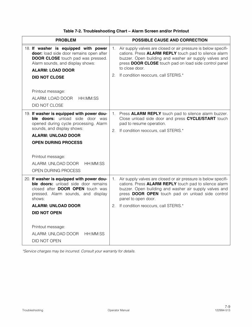
18. If washer is equipped with powerdoor: load side door remains open afterDOOR CLOSE touch pad was pressed.Alarm sounds, and display shows:
ALARM: LOAD DOOR
DID NOT CLOSE
Printout message:
ALARM: LOAD DOOR HH:MM:SS
DID NOT CLOSE
1. Air supply valves are closed or air pressure is below specifi-cations. Press ALARM REPLY touch pad to silence alarmbuzzer. Open building and washer air supply valves andpress DOOR CLOSE touch pad on load side control panelto close door.
2. If condition reoccurs, call STERIS.*
19. If washer is equipped with power dou-ble doors: unload side door wasopened during cycle processing. Alarmsounds, and display shows:
ALARM: UNLOAD DOOR
OPEN DURING PROCESS
Printout message:
ALARM: UNLOAD DOOR HH:MM:SS
OPEN DURING PROCESS
1. Press ALARM REPLY touch pad to silence alarm buzzer.Close unload side door and press CYCLE/START touchpad to resume operation.
2. If condition reoccurs, call STERIS.*
20. If washer is equipped with power dou-ble doors: unload side door remainsclosed after DOOR OPEN touch waspressed. Alarm sounds, and displayshows:
ALARM: UNLOAD DOOR
DID NOT OPEN
Printout message:
ALARM: UNLOAD DOOR HH:MM:SS
DID NOT OPEN
1. Air supply valves are closed or air pressure is below specifi-cations. Press ALARM REPLY touch pad to silence alarmbuzzer. Open building and washer air supply valves andpress DOOR OPEN touch pad on unload side controlpanel to open door.
2. If condition reoccurs, call STERIS.*
Table 7-2. Troubleshooting Chart – Alarm Screen and/or Printout
PROBLEM POSSIBLE CAUSE AND CORRECTION
*Service charges may be incurred. Consult your warranty for details.
7-9Troubleshooting Operator Manual 122994-513

21. If washer is equipped with power dou-ble doors: unload side door remainsopen after DOOR CLOSE touch padwas pressed. Alarm sounds, and displayshows:
ALARM: UNLOAD DOOR
DID NOT CLOSE
Printout message:
ALARM: UNLOAD DOOR HH:MM:SS
DID NOT CLOSE
1. Air supply valves are closed or air pressure is below specifi-cations. Press ALARM REPLY touch pad to silence alarmbuzzer. Open building and washer air supply valves andpress DOOR CLOSE touch pad on unload side controlpanel to close door.
2. If condition reoccurs, call STERIS.*
22. Display shows:
MAINTENANCE DUE
CALL SERVICE...
Printout message:
MAINTENANCE DUE !
Call STERIS.*
23. If washer is equipped with powerdoor(s): door safety switch detects anobstruction while door is closing. Alarmsounds, and display shows:
ALARM:
DOOR OBSTRUCTED
Printout message:
ALARM: DOOR OBSTRUCTED HH:MM:SS
1. Door movement obstructed. Press ALARM REPLY touchpad to silence alarm buzzer. Remove obstruction fromdoorway, press DOOR CLOSE touch pad and pressCYCLE/START touch pad to resume operation.
2. Door safety switch failed, call STERIS.*
24. Display is blank and printout message is:
BOARD COMMUNICATION
FAILURE 02
1. Communication between control board and I/O board hasbeen interrupted. Verify control cable is tightly connected.To reset control, turn power switch to OFF, then back ON.
2. If condition reoccurs, call STERIS.*
Table 7-2. Troubleshooting Chart – Alarm Screen and/or Printout
PROBLEM POSSIBLE CAUSE AND CORRECTION
*Service charges may be incurred. Consult your warranty for details.
7-10122994-513 Operator Manual Troubleshooting


