TM 55-4920-431-13 TECHNICAL MANUAL OPERATOR’S AVIATION UNIT AND INTERMEDIATE MAINTENANCE MANUAL FOR AUXILIARY POWER UNIT ELECTRONIC SEQUENCE UNIT MULTI-PURPOSE TEST SET P/N 161226-200 NSN 4920-01-121-0605 HEADQUARTERS, DEPARTMENT OF THE ARMY 31 MARCH 1983
Transcript
TM 55 -4920 -431 -13
T E C H N I C A L M A N U A L
O P E R A T O R ’ SA V I A T I O N U N I T A N D I N T E R M E D I A T E
M A I N T E N A N C E M A N U A L
F O R
A U X I L I A R Y P O W E R U N I TE L E C T R O N I C S E Q U E N C E U N I T
M U L T I - P U R P O S E T E S T S E TP / N 1 6 1 2 2 6 - 2 0 0
NSN 4920 -01 -121 -0605
H E A D Q U A R T E R S , D E P A R T M E N T O F T H E A R M Y
3 1 M A R C H 1 9 8 3
WARNING PAGE
HIGH VOLTAGE
High voltage is used in operation of test equipment. Death on con-tact can result if personnel fail to observe safety precautions.
TM 55-4920-431-13
a/(b blank)
by a miniature pointing hand.
Remove pages
i and ii1-3 and 1-44-17 and 4-18A-1 through A-8
---Index 1 and Index
2. Retain this sheet in
TM 55-4920-431-13C 1
HEADQUARTERSDEPARTMENT OF THE ARMY
WASHINGTON, D.C., 26 August 1985
Operator’sAviation Unit and Intermediate
Maintenance Manualfor
Auxiliary Power UnitElectronic Sequence UnitMulti-Purpose Test Set
P/N 161226-200NSN 4920-01-121-0605
TM 55-4920-431-13, 31 March 1983, is changed as follows:
1. Remove and insert pages as indicated below. New or changed text materialis indicated by a vertical bar in the margin. An illustration change is indicated
Insert pages
i and ii1-3 and 1-44-17 and 4-18A-1/A-2B-1 through B-7/B-8
2 Index 1 and Index 2
front of manual for reference purposes.
By Order of the Secretary of the Army:
Official:
DONALD J. DELANDROBrigadier General, United States Army
The Adjutant General
DISTRIBUTION:To be distributed in accordance with DA Form
requirements for All Rotary Wing Aircraft and All
JOHN A. WICKHAM, JR.General, United States Army
Chief of Staff
12-31, Operator, AVUM and AVIMFixed Wing Aircraft.
TM 55-4920-431-13
TECHNICAL MANUAL
NO. 55-4920-431-13
OPERATOR’S, AVIATION UNIT, AND INTERMEDIATEMAINTENANCE MANUAL
FORAUXILIARY POWER UNIT ELECTRONIC SEQUENCE UNIT
MULTI-PURPOSE TEST SETP/N 161226-200
NSN 4920-01-121-0605
REPORTING ERRORS AND RECOMMENDING IMPROVEMENTS
You can help improve this manual. If you find any mistakes or if you know of a way toimprove the procedures, please let us know. Mail your letter, DA Form 2028(Recommended Changes to publications and Blank Forms), or DA Form 2028-2 locatedin the back of this manual direct to: U. S. Army Aviation Systems Command,ATTN: AMSAV-MPSD, 4300 Goodfellow Blvd., St. Louis, MO 63120-1798. A reply willbe furnished to you.
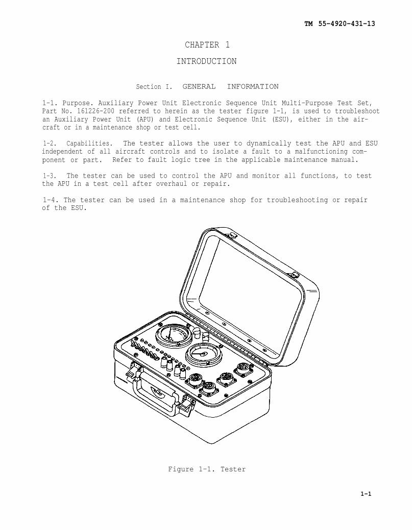
1-1. Purpose. Auxiliary Power Unit Electronic Sequence Unit Multi-Purpose Test Set,Part No. 161226-200 referred to herein as the tester figure 1-1, is used to troubleshootan Auxiliary Power Unit (APU) and Electronic Sequence Unit (ESU), either in the air-craft or in a maintenance shop or test cell.
1-2. Capabilities. The tester allows the user to dynamically test the APU and ESUindependent of all aircraft controls and to isolate a fault to a malfunctioning com-ponent or part. Refer to fault logic tree in the applicable maintenance manual.
1-3. The tester can be used to control the APU and monitor all functions, to testthe APU in a test cell after overhaul or repair.
1-4. The tester can be used in a maintenance shop for troubleshootingof the ESU.
or repair
Figure 1-1. Tester
1-1
TM 55-4920-431-13
1-5. Items Furnished. The following are furnished with the tester and are storedin the case lid.
Harness - P5, Part No. 161227-200Harness - P1, Part No. 161228-200Harness - P2, Part No. 161229-200
1-6. Tools and Test Equipment. Standard tools necessary to maintain the testerare contained in table 1-1.
Table 1-1. Tools and Test Equipment
Minimum Use Part/Model No.DescriptionSpecifications or Equivalent
Signal Converter Turbomach PartNo. ST93480
Oscillator 405 to 5693 Hz HP-204D
DC Power Supply 0 to 24V HP-6224B
Counter 405 to 5693 Hz HP-5315A
Digital Multimeter 32 to 204 ua Fluke 8024B
Simulation Device Turbomach PartNo. ST93930
Millivolt Supply 0 to 50 mv, Thermo Electricvariable Digimite/Multimite
1-8. WARRANTY. The tester is warranted by Turbomach for two years. Warranty starts on the date found onDA Form 2410 or DA Form 2408-16 in the logbook. Report all defects in material or workmanship to yoursupervisor who will take appropriate action.
1-9. MAINTENANCE FORMS AND RECORDS. Department of the Army forms and procedures used forequipment maintenance will be those prescribed by TM 38-750, the Army Maintenance Management System.
1-10. DESTRUCTION OF ARMY MATERIEL TO PREVENT ENEMY USE. Destroy tester when evacuation to safety is not possible. Refer to TM 750-244-1-4.
1-11. QUALITY ASSURANCE/QUALITY CONTROL (QA/QC). Refer to FM 55-411.
1-12. REPORTING EQUIPMENT IMPROVEMENT RECOMMENDATIONS (EIR). If your tester needsimprovement, let us know. Send us an EIR. You, the user are the only one who can tell us what you do not likeabout your equipment. Let us know why you do not like the design. Put in on SF368 Quality Deficiency Report(QDR). Mail it to us at:
CommanderUSAAVSCOMATTN: AMSAV-MPSD4300 Goodfellow Blvd.St. Louis, MO 63120-1798
1-4 Change 1
TM 55-4920-431-13
Section II. EQUIPMENT DESCRIPTION AND DATA
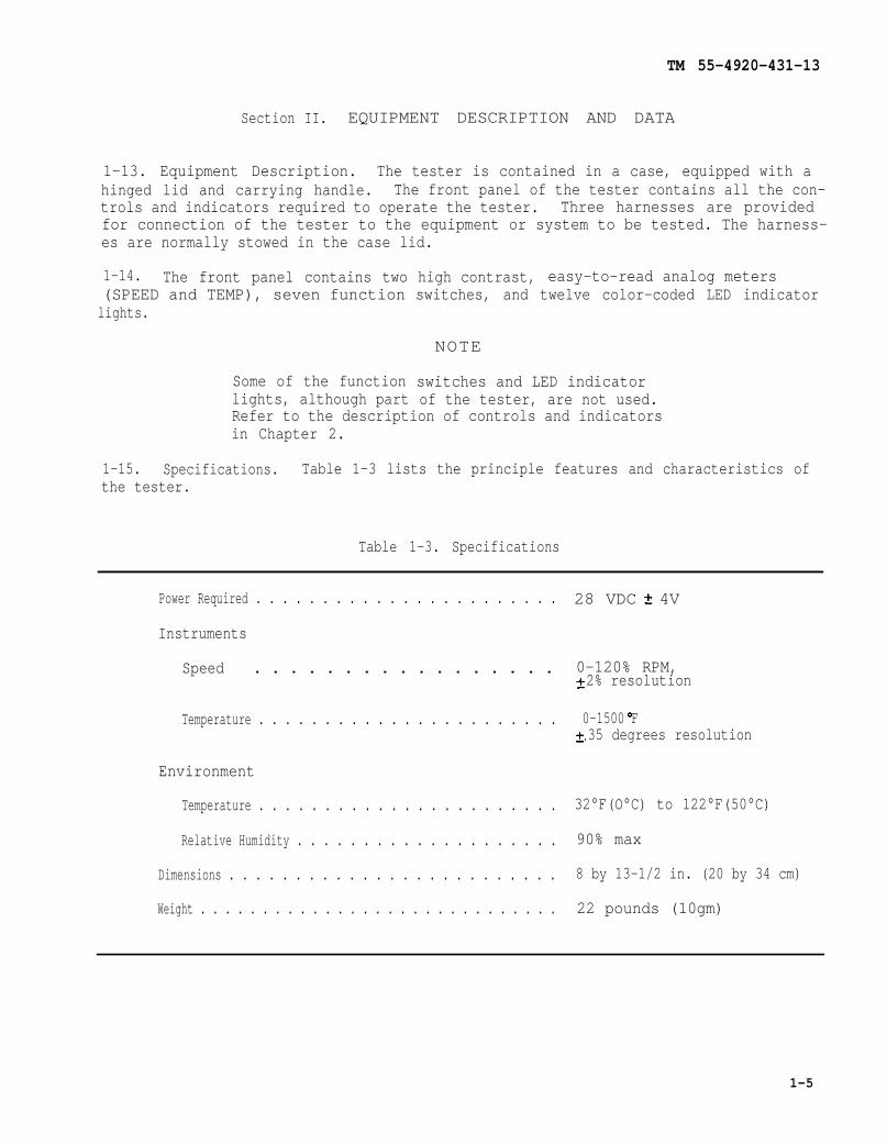
1-13. Equipment Description. The tester is contained in a case, equipped with ahinged lid and carrying handle. The front panel of the tester contains all the con-trols and indicators required to operate the tester. Three harnesses are providedfor connection of the tester to the equipment or system to be tested. The harness-es are normally stowed in the case lid.
1-14. The front panel contains two(SPEED and TEMP), seven functionlights.
Some of the functionlights, although part
high contrast, easy-to-read analog metersswitches, and twelve color-coded LED indicator
NOTE
switches and LED indicatorof the tester, are not used.
Refer to the description of controls and indicatorsin Chapter 2.
1-15. Specifications. Table 1-3 lists the principle features and characteristics ofthe tester.
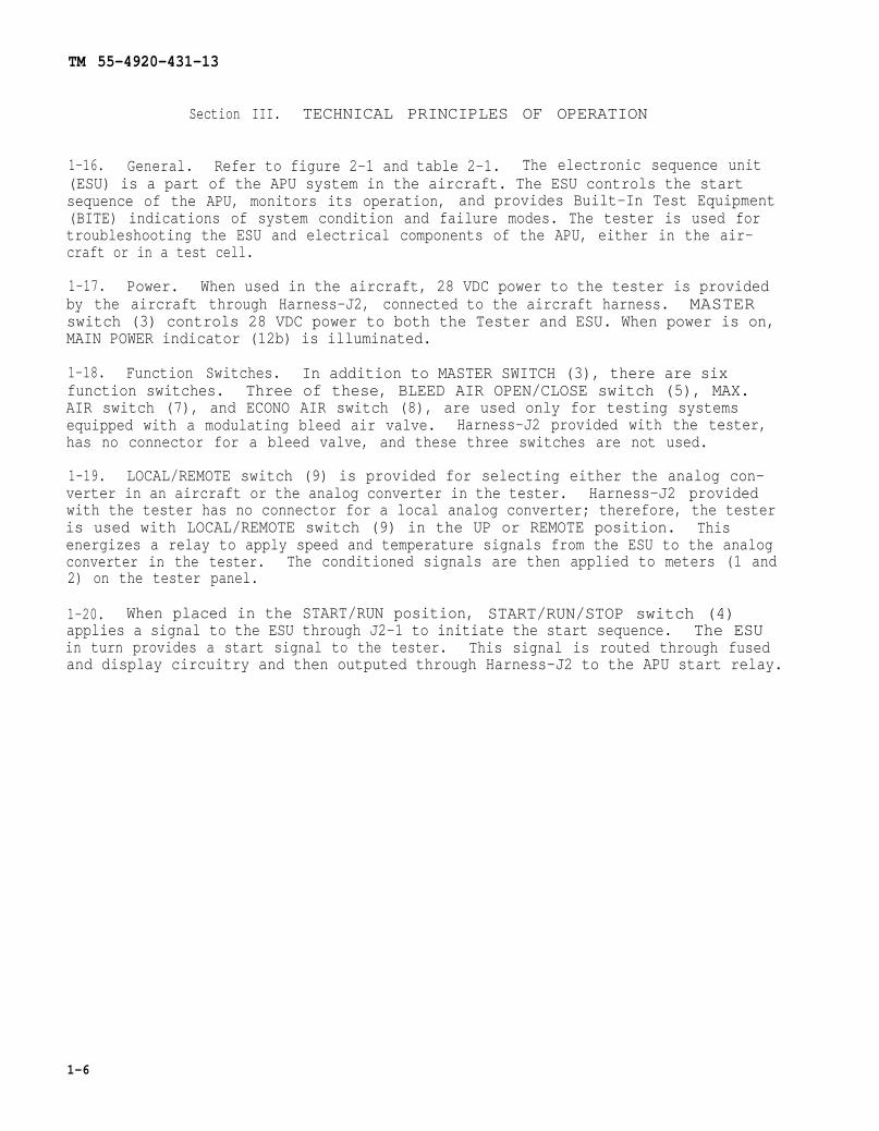
1-16. General. Refer to figure 2-1 and table 2-1. The electronic sequence unit(ESU) is a part of the APU system in the aircraft. The ESU controls the startsequence of the APU, monitors its operation, and provides Built-In Test Equipment(BITE) indications of system condition and failure modes. The tester is used fortroubleshooting the ESU and electrical components of the APU, either in the air-craft or in a test cell.
1-17. Power. When used in the aircraft, 28 VDC power to the tester is providedby the aircraft through Harness-J2, connected to the aircraft harness. MASTERswitch (3) controls 28 VDC power to both the Tester and ESU. When power is on,MAIN POWER indicator (12b) is illuminated.
1-18. Function Switches. In addition to MASTER SWITCH (3), there are sixfunction switches. Three of these, BLEED AIR OPEN/CLOSE switch (5), MAX.AIR switch (7), and ECONO AIR switch (8), are used only for testing systemsequipped with a modulating bleed air valve. Harness-J2 provided with the tester,has no connector for a bleed valve, and these three switches are not used.
1-19. LOCAL/REMOTE switch (9) is provided for selecting either the analog con-verter in an aircraft or the analog converter in the tester. Harness-J2 providedwith the tester has no connector for a local analog converter; therefore, the testeris used with LOCAL/REMOTE switch (9) in the UP or REMOTE position. Thisenergizes a relay to apply speed and temperature signals from the ESU to the analogconverter in the tester. The conditioned signals are then applied to meters (1 and2) on the tester panel.
1-20. When placed in the START/RUN position, START/RUN/STOP switch (4)applies a signal to the ESU through J2-1 to initiate the start sequence. The ESUin turn provides a start signal to the tester. This signal is routed through fusedand display circuitry and then outputed through Harness–J2 to the APU start relay.
1-6
TM 55-4920-431-13
CHAPTER 2
OPERATING INSTRUCTIONS
Section I. SERVICE
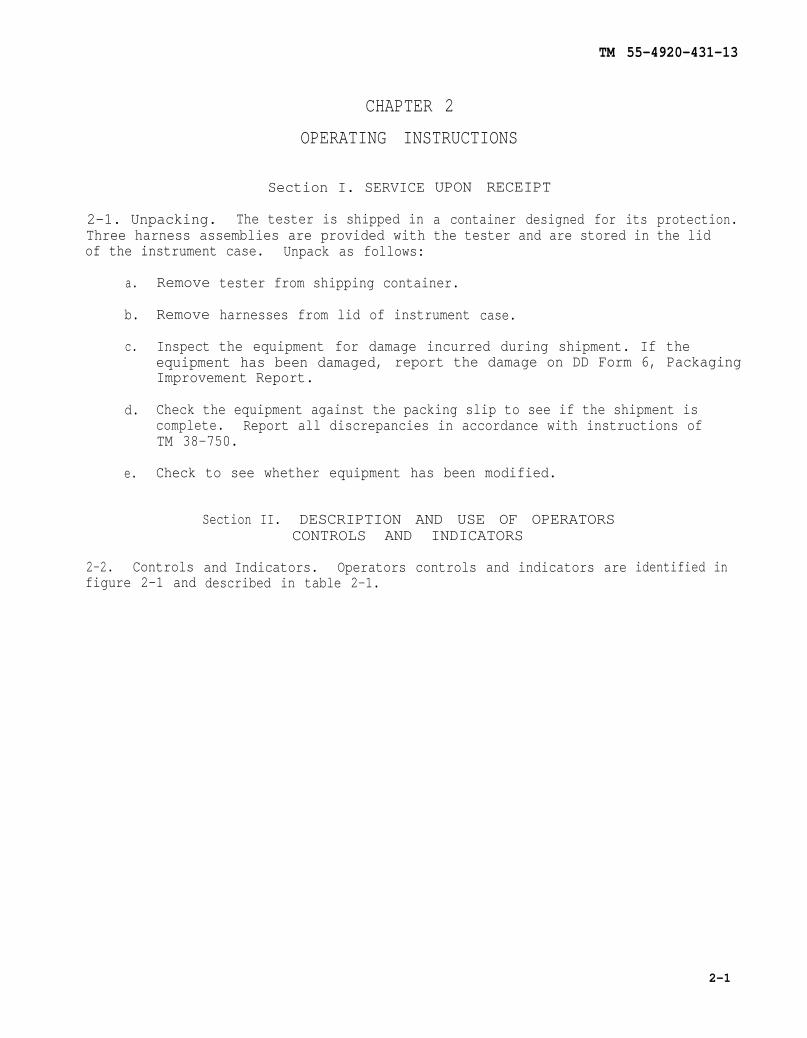
2-1. Unpacking. The tester is shipped inThree harness assemblies are provided withof the instrument case. Unpack as follows:
UPON RECEIPT
a container designed for its protection.the tester and are stored in the lid
a.
b.
c.
d.
e.
Remove
Remove
Inspect
tester from shipping container.
harnesses from lid of instrument case.
the equipment for damage incurred during shipment. If theequipment has been damaged, report the damage on DD Form 6, PackagingImprovement Report.
Check the equipment against the packing slip to see if the shipment iscomplete. Report all discrepancies in accordance with instructions ofTM 38-750.
Check to see whether equipment has been modified.
2-2. Controlsfigure 2-1 and
Section II. DESCRIPTION AND USE OF OPERATORSCONTROLS AND INDICATORS
and Indicators. Operators controls and indicators aredescribed in table 2-1.
identified in
2-1
Figure 2-1.
TM 55-4920-431-13
2-2
TM 55-4920-431-13
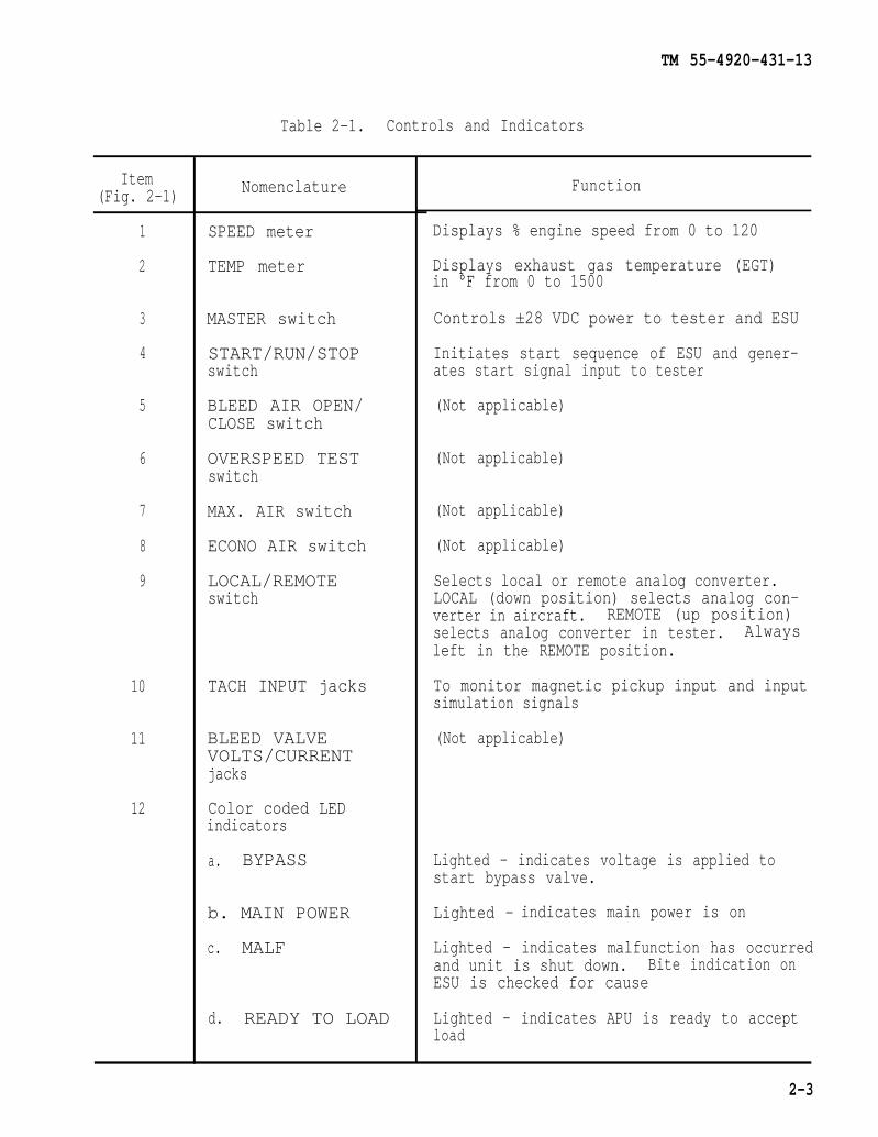
Table 2-1. Controls and Indicators
Item(Fig. 2-1)
1
2
3
4
5
6
7
8
9
10
11
12
Nomenclature
SPEED meter
TEMP meter
MASTER switch
START/RUN/STOPswitch
BLEED AIR OPEN/CLOSE switch
OVERSPEED TESTswitch
MAX. AIR switch
ECONO AIR switch
LOCAL/REMOTEswitch
TACH INPUT jacks
BLEED VALVEVOLTS/CURRENTjacks
Color coded LEDindicators
a. BYPASS
b. MAIN POWER
c. MALF
d. READY TO LOAD
Function
Displays % engine speed from 0 to 120
Displays exhaust gas temperature (EGT)in °F from 0 to 1500
Controls ±28 VDC power to tester and ESU
Initiates start sequence of ESU and gener-ates start signal input to tester
(Not applicable)
(Not applicable)
(Not applicable)
(Not applicable)
Selects local or remote analog converter.LOCAL (down position) selects analog con-verter in aircraft. REMOTE (up position)selects analog converter in tester. Alwaysleft in the REMOTE position.
To monitor magnetic pickup input and inputsimulation signals
(Not applicable)
Lighted – indicates voltage is applied tostart bypass valve.
Lighted – indicates main power is on
Lighted – indicates malfunction has occurredand unit is shut down. Bite indication onESU is checked for cause
Lighted – indicates APU is ready to acceptload
2-3
TM 55-4920-431-13
Item(Fig. 2-1)
13
14
15
16
17
Table 2-1. Controls and Indicators - Continued
Nomenclature
e. START COMMAND
f. MAX. AIR
g. ECONO AIR
h. START FUEL
i. MAIN FUEL
j. MAX. FUEL
k. OIL PRESSURE
l. BLEED VALVEOPEN
m. REMOTE
Connector J2
Connector J1
Connector J5
DIAGNOSTICconnector
Panel Light
Function
Lighted – indicates start command isinitiated
(Not applicable)
(Not applicable)
Lighted – indicates start fuel voltage onapproximately 5% RPM
Lighted – indicates main fuel voltage on,approximately 14% RPM
Lighted – indicates max. fuel voltage on,approximately 90% RPM + 5 sec. time out
(Not applicable)
(Not applicable)
Lighted – indicates remote analog conver-ter selected
Input/output connector for harness connec-tion to ESU and aircraft harness
Input connector for harness connection toESU
Output connector for harness connectionto APU
(Not applicable)
Illuminates meters
2-4
Section III. PREVENTIVE MAINTENANCE CHECKS AND
TM 55-4920-431-13
SERVICES
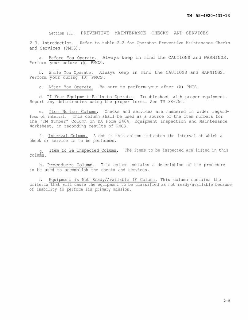
2-3. Introduction. Refer to table 2-2 for Operator Preventive Maintenance Checksand Services (PMCS).
a.Perform
b.Perform
c.
Before You Operate. Always keep in mind the CAUTIONS and WARNINGS.your before (B) PMCS.
While You Operate. Always keep in mind the CAUTIONS and WARNINGS.your during (D) PMCS.
After You Operate. Be sure to perform your after (A) PMCS.
d. If Your Equipment Fails to Operate. Troubleshoot with proper equipment.Report any deficiencies using the proper forms. See TM 38-750.
e. Item Number Column. Checks and services are numbered in order regard-less of interval. This column shall be used as a source of the item numbers forthe “TM Number” Column on DA Form 2404, Equipment Inspection and MaintenanceWorksheet, in recording results of PMCS.
f. Interval Column. A dot in this column indicates the interval at which acheck or service is to be performed.
g. Item to Be Inspected Column. The items to be inspected are listed in thiscolumn.
h. Procedures Column. This column contains a description of the procedureto be used to accomplish the checks and services.
i. Equipment is Not Ready/Available IF Column. This column contains thecriteria that will cause the equipment to be classified as not ready/available becauseof inability to perform its primary mission.
2-5
TM 55-4920-431-13
Table 2-2. Operator Preventive Maintenance Checks and Services
NOTE: Within designated interval, these checks are to be performed in the orderlisted.
B - Before D - During A - After
Item Interval Item to be Procedures Equipment Is
No. B D A Inspected Check for and have repaired or Not Ready/adjusted as necessary Available If:
1 Meters Cover glasses dirty, cracked Hand missingor broken. Hands bent or or bent, doesmissing. Meter must read zero. not read zero
2 Switches Check that switches are secur- Switch notely mounted to panel and oper– operationalate properly
3 Indicators Check that LED indicators are LED isclean and not broken broken
4 Meter Check that lamps are clean andLamps not broken; lampholders are
not cracked, chipped, orbroken
5 Binding Check that plastic caps are notPosts cracked or chipped, caps turn
freely, posts are free of dirtand grease
6 Front Check that panel is clean, let-Panel tering is clean and legible, all
screws are installed and tight
7 Connectors Check for bent or broken pins. Connector isCheck that mounting screws are damagedinstalled and tight
8 Harnesses Check for kinks, twists, dete- Harness isriorated insulation or sleeving. damagedCheck that harness and panelconnectors mate properly
9 Case Check hinges and latches fordamage. Check for cracksand breaks
2-6
TM 55-4920-431-13
Section IV. OPERATION UNDER USUAL CONDITIONS
2-4. Preparation for Use.
a. Turn pressure equalizer knob to OPEN. Open case. Turn knob to CLOSE.
b. Remove harnesses from case lid.
c. Connect harnesses as shown in figures 2-2 or 2-3.
d. Zero meters.
e. Perform your before (B) PMCS.
2-5. APU Test. Connect the tester for use in the aircraft in accordance with figure2-2. Perform test in accordance with the applicable maintenance manual.
NOTE
During tests, leave BLEED AIR OPEN/CLOSEMAX. AIR switch, and ECONO AIR switch inposition.
switch,down
2-6. ESU Test. Bench test of the ESU is accomplished by using an oscillator tosimulate the tach input from the magnetic pickup in the APU. Millivolt supplies areused to simulate EGT thermocouple inputs from the APU. Connections are madethrough the ST93930 simulation device as shown in figure 2-3. Perform check inaccordance with TM 55-1520-240-T.
Section V. OPERATION UNDER UNUSUAL CONDITIONS
Not applicable.
2-7
TM 55-4920-431-13
Figure 2-2. Connecting Tester for Use in Aircraft
2-8
TM 55-4920-431-13
Figure 2-3. Connecting Tester for Bench-Check of ESU
2-9/(2-10 blank)
TM 55-4920-431-13
CHAPTER 3
AVUM MAINTENANCE INSTRUCTIONS
Section I. REQUIREMENTS
3-1. Personnel. Maintenance procedure in this chapter will be performed by:
68F Aircraft Electrician.
3-2. Parts. Replaceable parts are listedrefer to TM 55-4920-431-23P.
Section II.
and illustrated in Chapter 5. When requisitioning parts,
TROUBLESHOOTING
3-3. Introduction. The following troubleshooting procedures are to find faults in thetester itself, and not in the APU or ESU being tested. The troubles covered are thosethat may be encountered with the tester connected for use as shown in figure 2-2 or2-3. Refer to figure 3-1 for identification of connector contacts.
Figure 3-1. Connector Contact Arrangement
3-1
TM 55-4920-431-13
TROUBLESHOOTING PROCEDURE 1. MAINNOT ILLUMINATE
POWER LIGHT DOES
TROUBLE SHOOTING PROCEDURE 2. METER DOES NOTINDICATE ENGINE SPEED OR TEMP
3-2
(PARA 3-4).
TM 55-4920-431-13
TROUBLESHOOTING PROCEDURE 3. METER LIGHT DOES NOTCOME ON
Section III. MAINTENANCE PROCEDURES
3-4. Meter Lamp Replacement.
a.
b.
c.
d.
e.
Open case lid.
Pull up on top of lampholder (21, figure 5-2) and remove top with lamp(20).
Remove lamp and discard. Install replacement lamp into top of lampholder.
Press top of lampholder into base and seat.
Close case lid.
3-3/(3-4 blank)
TM 55-4920-431-13
CHAPTER 4
AVIM (CRC) MAINTENANCE INSTRUCTIONS
Section I. REQUIREMENTS
4-1. Personnel. Maintenance procedures
35H Calibration Specialist
4-2. Tools. Refer to paragraph 1-6 and
4-3. Parts. Replaceable parts are listed
4-4. Materials. Expendable supplies andfied in the applicable repair instructions.for complete identification.
in this chapter will be performed by:
table 1-1 for complete identification.
and illustrated in Chapter 5.
materials required for repair are identi-Refer to paragraph 1-7 and table 1-2
Section II. PREVENTIVE MAINTENANCE CHECKS AND SERVICES (PMCS)
4-5. Introduction. Refer to table 4-1 for preventive maintenance checks andservices. Following is an explanation of the columns and codes used in the table.
a. Item Number Column. Checks and services are numbered in order regard-less of interval. This column shall be used as a source of the item num-bers for the “TM Number” Column on DA Form 2404, Equipment Inspectionand Maintenance Worksheet, in recording results of PMCS.
b. Items to be Inspected Column. The items to be inspected are listed in this column.
c. Procedures Column. This column contains a description of the procedure to be usedto accomplish the checks and services. Appropriate references to the applicablemaintenance instructions for repair or replacement are included.
4-1
TM 55-4920-431-13
Table 4-1. Preventive Maintenance Checks and Services
A-Annually
Interval ItemItem To Be ProceduresNo. A Inspected
NOTE
Procedures for gaining accessto inside of case are describedin paragraph 4-7.
1 Relay Check for tightness in socket and that hold(1, fig 5-3) down spring is in place. Check for loose
wire connections
2 Analog Check that harness is properly attached. CheckConverter for broken wires and deteriorated insulation.(19, fig 5-1) Check screws (20, fig 5-1) for tightness.
3 Fuses Check that fuses are proper size and type(7, fig 5-3) and in place in fuseblock (11, fig 5-3)
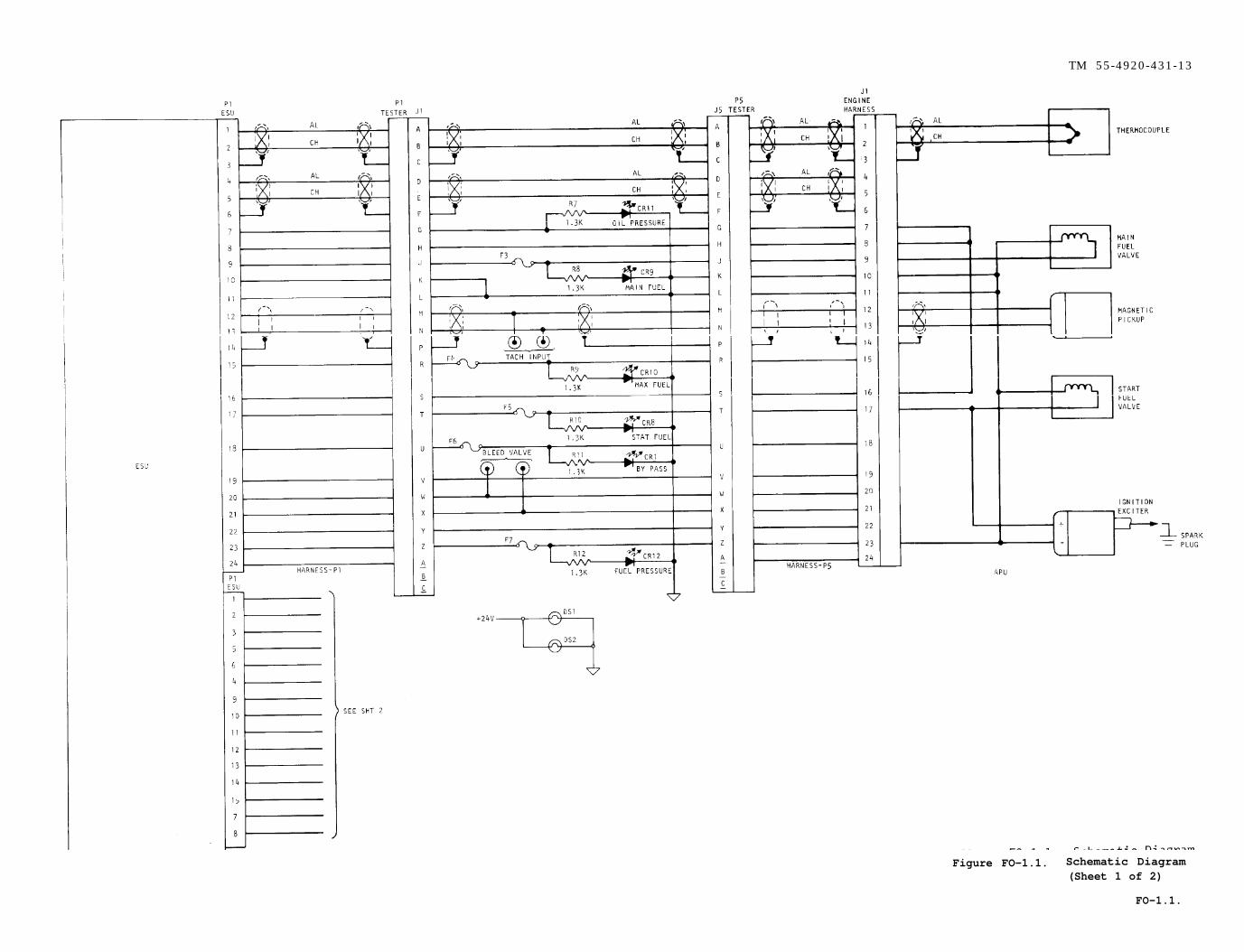
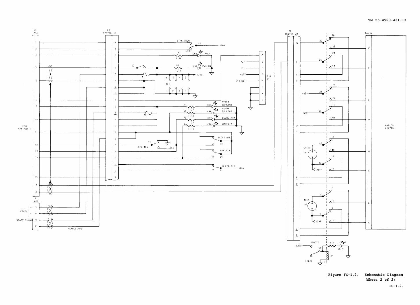
4-6. Introduction. The following troubleshooting procedures are to find and correct faultsin the tester itself, and not in the APU or ESU being tested. Additional continuity checkscan be performed by using schematic diagram, figure FO-1 and wiring diagram, figureFO-2, and by testing in accordance with paragraph 4-8. Refer to figure 3-1 foridentification of connector contacts.
NOTE
Refer to wiring diagram, figure FO-2 to locate compo-nents, wires, connectors, pins and terminals wheretest connections are to be made. The wiring diagramcovers only internal wiring of the tester. Refer toschematic diagram, figure FO-1, for wiring ofharnesses.
4-2
PARA 4-7
PARA 4-21
PARA 4-30
PARA 4-13c
PARA 4-30
PARA 4-18
PARA 4-19
TM 55-4920-431-13
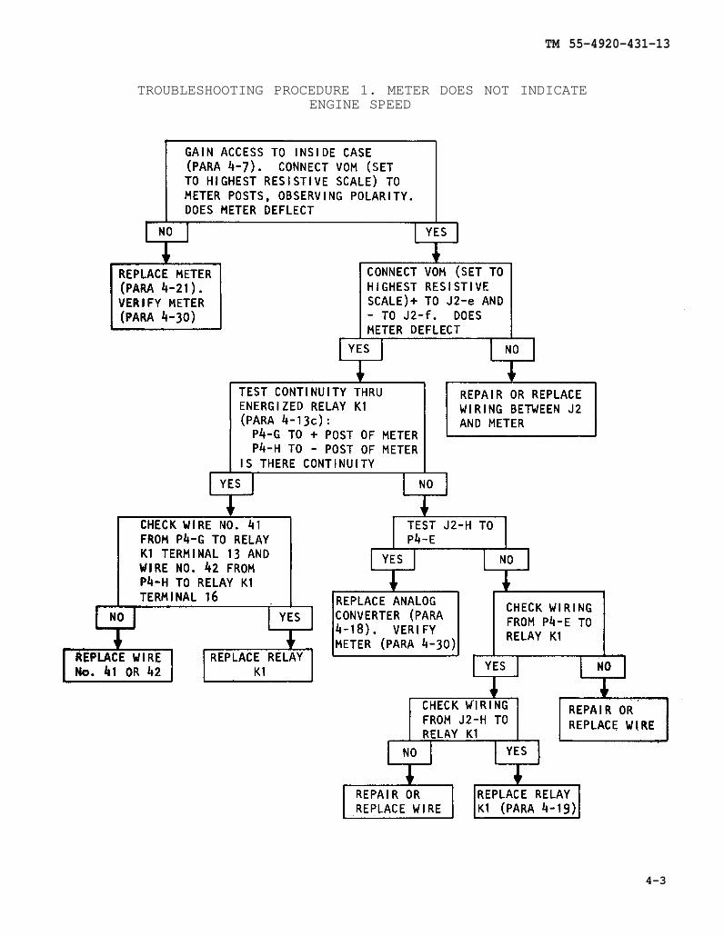
TROUBLESHOOTING PROCEDURE 1. METER DOES NOT INDICATEENGINE SPEED
4-3
PARA 4-7
PARA 4-21
PARA 4-30
PARA 4-13c
(PARA 4-18).
PARA 4-30
PARA 4-19
TM 55-4920-431-13
TROUBLESHOOTING PROCEDURE 2. METER DOES NOTINDICATE TEMP
4-4
PARA 4-7
PARA 4-20
PARA 4-26
PARA 4-9b
PARA 4-27
PARA 4-22
TM 55-4920-431-13TROUBLESHOOTING PROCEDURE 3. MAIN POWER
LED INDICATOR CR2 DOES NOT COME ON
4-5
TM 55-4920-431-13
TROUBLESHOOTING PROCEDURE 4. MAIN LEDINDICATOR CR3 DOES NOT COME ON
4-6
TM 55-4920-431-13
TROUBLESHOOTING PROCEDURE NO. 5.READY TO LOAD LED INDICATOR CR4 DOES
NOT COME ON
4-7
TM 55-4920-431-13
TROUBLESHOOTING PROCEDURE NO. 6START COMMAND LED INDICATOR CR5 DOES
NOT COME ON
4-8
TM 55-4920-431-13
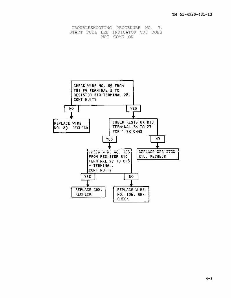
TROUBLESHOOTING PROCEDURE NO. 7.START FUEL LED INDICATOR CR8 DOES
NOT COME ON
4-9
TM 55-4920-431-13
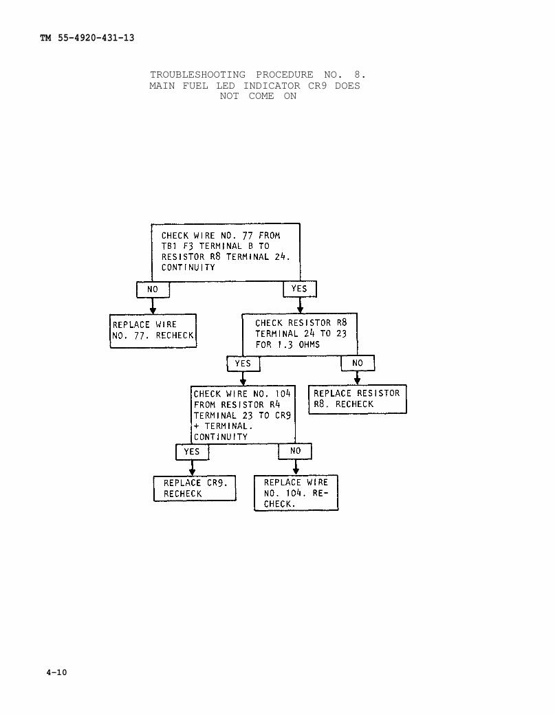
TROUBLESHOOTING PROCEDURE NO. 8.MAIN FUEL LED INDICATOR CR9 DOES
NOT COME ON
4-10
TM 55-4920-431-13
TROUBLESHOOTING PROCEDURE NO. 9.MAX FUEL LED INDICATOR CR10 DOES
NOT COME ON
4-11
TM 55-4920-431-13
TROUBLESHOOTING PROCEDURE NO. 10. REMOTELED INDICATOR CR13 DOES NOT COME ON
4-12
Section IV.
4-7. Access to Inside Case for
TM 55-4920-431-13
MAINTENANCE PROCEDURES
Maintenance. Gain access to inside the case formaintenance purposes, as follows:
a.
b.
c.
d.
e.
f.
g.
h.
Turn pressure equalizer knob to OPEN.
Open two butterfly fasteners on front of case. Open lid, fold back, andremove from case.
Turn pressure equalizer knob to CLOSE.
Remove ten screws (17, figure 5-1) and washers (18) securing front panelassembly (16) to case (26).
Lift front panel assembly from case and lay over for access to componentsfor maintenance.
After completion of maintenance, lift front panel assembly back into positionin case aligning holes for retaining screws.
Reinstall ten screws and washers.
Install lid on case. Close lid and secure butterfly fasteners.
4-8. Testing. The following paragraphs describe tests that may be performed inconjunction with troubleshooting to isolate a faulty component or wiring.
4-9. Test Switches. Refer to wiring diagram, figure FO-2. Test switches as follows:
a. Gain access to inside of case per paragraph 4-7.
Be sure outside electrical power is not appliedto tester during continuity checks. Damage tometers and other components can result.
b. Test MASTER Switch (S7).
1. Unsolder wire no. 109 at switch.
2. Connect VOM + lead to switch (S7) center terminal and - lead to switch(S7) lower terminal.
3. With switch toggle in down position, the VOM should read infinite ohms.With switch toggle in up position, the VOM should read zero ohms.
4. Disconnect VOM and
c. Test START/RUN/STOP
1. Connect VOM + lead(S1) lower terminal.
resolder wire no. 109.
Switch (S1).
to switch (S1) center terminal and - lead to switch
4-13
TM 55-4920-431-13
2. WithWith
switch toggle in down position, the VOM should read infinite ohms.switch toggle in up position, the VOM should read zero ohms.
3. Move VOM - lead to switch (S1) upper terminal. The VOM should readinfinite ohms.
4. Move switch toggle to down position. The VOM should read zero ohms.
5. Disconnect VOM.
d. Test LOCAL/REMOTE Switch (S6).
1. Unsolder wire no. 52 at switch.
2. Connect VOM + lead to switch (S6) center terminal and - lead to switch(S6) lower terminal.
3. With switch toggle in down position, the VOM should read infinite ohms.With switch toggle in up position, the VOM should read zero ohms.
4. Disconnect VOM and resolder wire no. 52 to lower terminal of switch(S6).
4-10. Test LED Indicators. If an LED indicator fails to light when it is supposed to,test in accordance with the troubleshooting procedures in Section III.
4-11. Test Meter Lamp Holder. Apply 24 VDC to J2-Z and J2-a. Both meter lamps(DS1 and DS2) should light. Isolate trouble to wiring or lamp holder. Repair wir-ing (para 4-27) or replace lamp holder (para 4-16), as required.
4-12. Test Fuses. Perform continuity test of each fuse to determine if they areblown. If blown, replace fuses (para 4-20).
4-13. Test Relay. Perform continuity test of relay (K1) as follows:
a. Gain access to inside of case per paragraph 4-7.
b. Set VOM to OHMCheck continuity
J2-cJ2-dJ2-eJ2-t
scale X1. Zero VOM. Refer to wiring diagram, figure FO-2.as follows:
to -post M2 J2-X to J2-Hto +post M2 J2-Y to J2-Gto +post M1 J2-T to J3-Gto -post M1 J2-U to J3-H
NOTE
Remove power between checks. Only (K1)is energized for following test.
4-14
c. Refer to wiring diagram, figure FO-2.Connect 28 vdc to unused terminal ofground lead to ground buss indicator
P4-A to - post M2P4-K to + post M2P4-G to + post M1P4-H to - post M1
d. Replace relay if defective (para 4-19).
TM 55-4920-431-13
Disconnect P4 from analog converter.LOCAL/REMOTE switch S6. Connectlights. Check continuity as follows:
P4-E to J2-HP4-F to J2-GP4-C to J3-GP4-D to J3-H
Reconnect P4 to analog convertor.
4-14. Test Harnesses. Perform continuity test of harness – P1, harness – P2, andharness - P5. Refer to schematic diagram, figure FO-1, and check each wire.
4-15. Replacement. The following paragraphs describe procedures for replacementof components.
4-16.
a.
b.
c.
d.
e.
f.
g.
h.
4-17.
a.
b.
c.
d.
e.
f.
Lampholder Replacement.
Gain access to inside of case per paragraph 4-7.
Unscrew electrical connector to lamp holder (21, figure 5-2) and remove.
Loosen retaining nut on lamp holder and remove nut.
Remove lampholder from panel.
Install replacement lampholder into panel.
Install retaining nut on lampholder and tighten.
Remove top of lampholder and install lamp. Reinstall onto base.
Reinstall front panel and case lid.
Binding Post Replacement.
Gain access to inside of case per paragraph 4-7.
Unsolder wires from binding post (10 or 11, figure 5-2).
Remove retaining nut mounting binding post to panel. Remove bindingpost and insulator from panel.
Install replacement binding post with insulator onto panel. Install retain-ing nut and tighten.
Solder wire leads to binding post.
Reinstall panel and case lid.
4-15
TM 55-4920-431-13
4-18.
a.
b.
c.
d.
e.
f.
g.
4-19.
a.
b.
c.
d.
e.
4-20.
a.
b.
c.
d.
4-21.
a.
b.
c.
d.
Analog Converter Replacement.
Gain access to inside of case per paragraph 4-7.
Disconnect electrical connector (P4) from control
Remove top four screws (20), washers (21), and
assembly (19, figure 5-1).
control assembly (19).
Install replacement control assembly (19) and secure with four screws (20)and washers (21).
Connect electrical connector (P4) to control assembly (19).
Verify meter operation in accordance with paragraph 4-30.
Reinstall panel and case lid.
Relay Replacement.
Gain access to inside case per paragraph 4-7.
Lift relay hold down spring (5, figure 5-3) from socket (4).
Pull relay (1) out of socket (4).
Install replacement relay (1) into socket (4). Reinstall relay hold downspring (5) over relay.
Reinstall panel and case lid.
Fuse Replacement.
Gain access to inside case per paragraph 4-7.
Lift fuse (7, figure 5-3) from fuse block (11).
Install replacement fuse.
Reinstall panel and case lid.
Meter Replacement.
Gain access to inside case per paragraph 4-7.
Refer to wiring diagram, figure FO-2 and identify wire leads to be disconnec-ted from meter. Wires 45, 46, and 47 connect to TEMP meter (M2). Wires48, 49, and 50 connect to SPEED meter (M1).
Loosen and remove nuts from meter posts. Remove wire leads from posts.
Remove three retaining screws and nuts mounting the SPEED meter (M1) (1,figure 5-2) or TEMP meter (M2) (2, figure 5-2) to the panel.
4-16
TM 55-4920-431-13
e.
f.
g.
h.
i.
j.
4-22.
a.
b.
c.
d.
e.
f.
g.
h.
4-23.
a.
b.
c.
d.
e.
f.
g.
4-24.
a.
Note the meter position and remove meter from panel.
Install replacement meter, noting previous meter position.
Install three retaining screws and nuts to secure meter to panel.
Refer to wiring diagram, figure FO-2. Connect wire leads to meter posts andinstall nuts on posts. Tighten nuts.
Verify meter in accordance with paragraph 4-30.
Reinstall panel and case lid.
Switch Replacement.
Gain access to inside case per paragraph 4-7.
Refer to wiring diagram, figure FO-2. Identify wire leads at switch to be re-placed.
Unsolder wire leads from switch terminals.
Remove retaining nut mounting switch (12, figure 5-2) to panel. Removeswitch noting index position.
Refer to wiring diagram, figure FO-2. Solder wire leads to switch terminals.
Reinstall panel and case lid.
LED Indicator Replacement.
Gain access to inside case per paragraph 4-7.
Refer to wiring diagram, figure FO-2. Identifyindicator (CR1 through CR12) to be replaced.
wire leads to defective LEDUnsolder wire leads.
Press on rear of LED indicator (17, 18, or 19, figure 5-2) to remove frompanel.
Install replacement LED indicator by pressing through front of panel.
Refer to wiring diagram, figure FO-2. Solder wire leads to LED indicator.
Install cap (13, 14, 15, or 16) on LED indicators.
Reinstall panel and case lid.
Instrument Case Replacement.
Remove ten screws (17, figure 5-1) and washers (18) securing front panelassembly (16) to case (26).
4-17
TM 55-4920-431-13
b.
c.
d.
e.
f.
g.
Lift front panel assembly (16) out of case (26).
Disconnect electrical connector (P4) from control assembly (19).
Remove four screws (24) securing plate assembly (23) to case (26).
Lift front panel assembly (16) and plate assembly (23) from case (26).
Remove screws (20), washers (21), spacers (22) and control assembly (19).
Install control assembly (19) into replacement case (26) and secure with screws (20), washers (21), andspacers (22).
h. Install plate assembly (23) in case (26) and secure with four screws (24).
i. Connect electrical connector (P4) to control assembly (19).
j. Install front panel assembly (16) into case (26) and secure with ten screws (17) and washers (18).
4-25. REPAIR. The following paragraphs describe repair of the tester.
4-26. HARNESS REPAIR. Refer to figure FO-1 for wiring of harness connectors. Replace damaged or deteriorated wire, sleeving, and pins. Refer to General Aircraft Maintenance Manual TM 55-1500-204-25/1 to
repair connectors. Use following materials as required (ref table 1-2).
Pins
Insulated Sleeving, Type F, Form U, Grade A, Class I, Category I, Black, per MIL-I-631
Thermocouple Wire K/ALKTW-20F-KK, Thermo Electric Co., Inc. Saddle Brook, NY
Shielded Pair Wire, Teflon Coated, Type E, per MIL-W-16878
4-27. TESTER WIRING. Refer to wiring diagram, figure FO-2. Replace all damaged or deteriorated wiring.Use following materials as required (ref table 1-2).
T/C Wire, M5846-1-B-1/24A and M5846-1-B-1/24C per MIL-W-5846/1
Wire, Type 3, 22 AWG, per MIL-W-16878
Strap, Tiedown, Adjustable, MS3367-1-9
Shrink Tubing
Crimp-On Terminal Lugs
4-28. PAINTING. Refinish exterior of case (26, figure 5-1) as required. Paint yellow, color number 13538 perFED-STD-595A. Renew lettering in gloss black, color number 17038 per FED-STD-595A.
4-29. FRONT PANEL MARKINGS. Renew nomenclature on front panel. Silkscreen black per MIL-STD-130.
4-18 Change 1
TM 55-4920-431-13
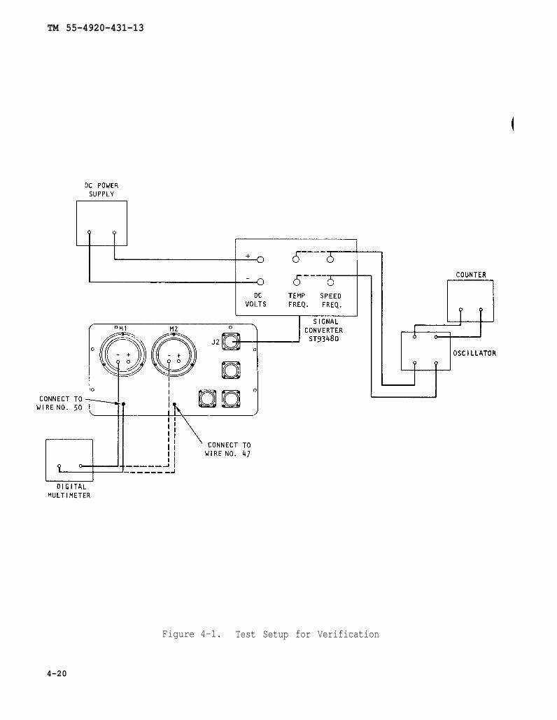
4-30. Verification. Verification of the meters shall be checked annually, and follow-ing replacement of the analog converter or a meter. If the condition of a tester isunknown, a verification shall be performed before using the tester. Perform verifi-cation
a.
b.
c.
d.
e.
f.
g.
h.
i.
j.
k.
l.
m.
n.
o.
p.
q.
as follows. Refer to figure 4-1 for test setup.
Gain access to inside of case per paragraph 4-7.
Disconnect negative terminal wire (wire no. 50) from SPEED meter.
Connect digital multimeter in series with the SPEED meter and disconnectedwire, observing polarity.
Set the multimeter mode selector switch to read amperes.
Be careful not to disconnect test wiring or short outleads. Damage to components or faulty readings canresult.
Lay front panel assembly on case.
Mechanically zero SPEED and TEMP meters.
Connect signal converter ST93480 to tester connector J2.
Position dc power supply adjacent to tester. Turn output knob fully counter-clockwise.
Connect power output terminals to dc voltage input terminals of signal con-verter ST93480 observing polarity.
High voltage is used in operation of test equipment.Death on contact may result if personnel fail toobserve safety precautions.
Be sure power switch is in off position and connect power cord to 100 voltsource.
Connect oscillator frequency output to speed frequency input terminals ofsignal converter ST93480.
Turn variable attenuator knob to maximum.
Turn attenuator select switch to 5 volt peak-to-peak setting.
Turn vernier frequency dial to zero Hertz.
Turn Hertz multiplier power switch to on.
Connect oscillator power cable to 110 volt source.
Turn gage select switch of frequency counter to AUTO.
4-19
TM 55-4920-431-13
Figure 4-1. Test Setup for Verification
4-20
TM 55-4920-431-13
r.
s.
t.
u.
v.
w.
x.
y.
z.
aa.
ab.
ac.
ad.
ac.
af.
ag.
ah.
ai.
aj.
ak.
al.
am.
Turn wave form select switch to sine-wave setting.
Turn sensitivity knob to mid-scale range setting.
Connect output terminals of oscillator to input terminals of counter.
Connect counter power cable to 110 volt source.
Place LOCAL/REMOTE switch on tester to REMOTE.
Turn dc power supply on.
Turn variable output voltage knob clockwise until output meter indicates 24volts.
Set counter power switch to on.
Set MASTER switch on tester to on (up). Verify that MAINindicator light comes on.
Adjust oscillator to each % RPM indication shown in table 4-2frequency and current readings.
Decrease the oscillator frequency to zero.
Set MASTER switch on tester to off (down).
Disconnect leads from speed frequency input terminals of signaland connect to temperature frequency input terminals.
Disconnect negative terminal wire (wire no. 47) from TEMP meter.
Connect digital multimeter in series with TEMP meter and disconnected wire.
Check that multimeter mode selector switch is set to read amperes.
Be careful not to disconnect test wiring or shortout leads. Damage to components or faulty read-ings can result.
Lay front panel assembly back on case.
Set MASTER switch on tester to on (up).
Adjust oscillator to each °F indication shown in table 4-3 and check inputfrequency and current readings.
Set MASTER switch on tester to off (down).
Disconnect meter leads from TEMP meter circuit.
4-21
TM 55-4920-431-13
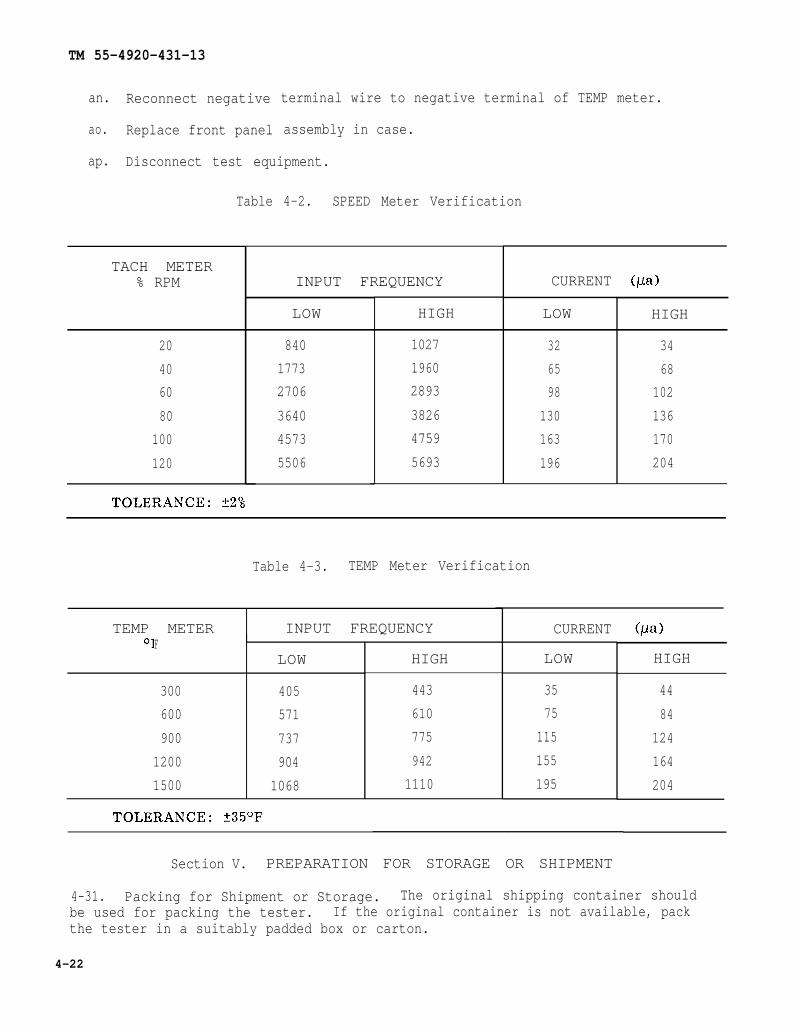
an. Reconnect negative
ao. Replace front panel
terminal wire to negative terminal of TEMP meter.
assembly in case.
ap. Disconnect test equipment.
Table 4-2. SPEED Meter Verification
TACH METER% RPM
20
40
60
80
100
120
INPUT FREQUENCY
LOW
840
1773
2706
3640
4573
5506
HIGH
1027
1960
2893
3826
4759
5693
CURRENT
LOW
32
65
98
130
163
196
HIGH
34
68
102
136
170
204
Table 4-3. TEMP Meter Verification
TEMP METER INPUT FREQUENCY F
LOW
300 405
600 571
900 737
1200 904
1500 1068
HIGH
443
610
775
942
1110
CURRENT
LOW
35
75
115
155
195
HIGH
44
84
124
164
204
Section V. PREPARATION FOR STORAGE OR SHIPMENT
4-31. Packing for Shipment or Storage. The original shipping container shouldbe used for packing the tester. If the original container is not available, packthe tester in a suitably padded box or carton.
4-22
TM 55-4920-431-13
CHAPTER 5
PARTS LIST
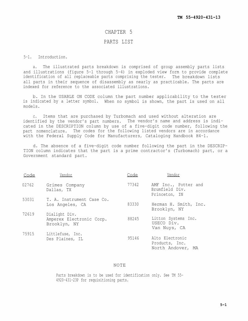
5-1. Introduction.
a. The illustrated parts breakdown is comprised of group assembly parts listsand illustrations (figure 5-1 through 5-4) in exploded view form to provide completeidentification of all replaceable parts comprising the tester. The breakdown listsall parts in their sequence of disassembly as nearly as practicable. The parts areindexed for reference to the associated illustrations.
b. In the USABLE ON CODE column the part number applicability to the testeris indicated by a letter symbol. When no symbol is shown, the part is used on allmodels.
c. Items that are purchased by Turbomach and used without alteration areidentified by the vendor’s part numbers. The vendor’s name and address is indi-cated in the DESCRIPTION column by use of a five-digit code number, following thepart nomenclature. The codes for the following listed vendors are in accordancewith the Federal Supply Code for Manufacturers, Cataloging Handbook H4-1.
d. The absence of a five-digit code number following the part in the DESCRIP-TION column indicates that the part is a prime contractor’s (Turbomach) part, or aGovernment standard part.
Code Vendor Code
02762 Grimes Company 77342Dallas, TX
53031 T. A. Instrument Case Co.Los Angeles, CA 83330
72619 Dialight Div.Amperex Electronic Corp. 88245Brooklyn, NY
75915 Littlefuse, Inc.Des Plaines, IL 95146
Vendor
AMF Inc., Potter andBrumfield Div.Princeton, IN
Herman H. Smith, Inc.Brooklyn, NY
Litton Systems Inc.USECO Div.Van Nuys, CA
Alto ElectronicProducts, Inc.North Andover, MA
NOTE
Parts breakdown is to be used for identification only. See TM 55-4920-431-23P for requisitioning parts.
5-1
TM 55-4920-431-13
Figure 5-1. APU Tester
5-2
TM 55-4920-431-13
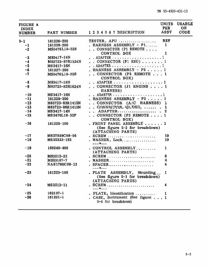
FIGURE & UNITS USABLEINDEX PER ONNUMBER PART NUMBER 1 2 3 4 5 6 7 DESCRIPTION ASSY CODE
a. This Maintenance Allocation Chart (MAC) assigns maintenancedance with the Three Levels of Maintenance concept for army aircraft.
functions in accor-These maintenance
levels: Aviation Unit Maintenance (AVUM), Aviation Intermediate Maintenance (AVIM) andDepot Maintenance are depicted on the MAC as:
AVUM which corresponds to the O code in the Repair Parts and SpecialTools List (RPSTL).
AVIM which corresponds to the F code in the Repair Parts and SpecialTools List (RPSTL).
DEPOT which corresponds to the D code in the Repair Parts and SpecialTools List (RPSTL).
b. The maintenance to be performed below depot and in the field is described asfollows:
1. Aviation Unit Maintenance (AVUM). AVUM activities will be staffed andequipped to perform high frequency “On-Equipment” maintenance tasks required to retainor return equipment to a serviceable condition. The maintenance capability of the AVUMwill be governed by the MAC and limited by the amount and complexity of support equipment,facilities required, and number of spaces and critical skills available. The range andquantity of authorized spare modules/components will be consistent with the mobility re-quirements dictated by the air mobility concept. (Assignment of maintenance tasks todivisional company size aviation units will consider the overall maintenance capability ofthe division, the requirement to conserve personnel and equipment resources and airmobility requirements).
(a) Company Size Aviation Units. Perform those tasks which consist pri-marily of preventive maintenance and maintenance repair and replacement functions asso-ciated with sustaining a high level of equipment operational readiness. Perform mainte-nance inspections and servicing to include daily, intermediate, periodic and specialinspections as authorized by the MAC or higher headquarters. Identify the cause ofequipment system malfunctions using applicable technical manual troubleshooting instruc-tions. Built-In-Test Equipment (BITE), installed instruments, or easy to use TestMeasurement and Diagnostic Equipment (TMDE). Replace worn or damaged modules/components which do not require complex adjustments or system alignments and whichcan be removed/installed with available skills, tools and equipment. Perform operationaland continuity checks and make minor repairs. Perform servicing, functional adjustments,and minor repair/replacement. Evacuate unserviceable modules/components and enditems beyond the repair capability of AVUM to the supporting AVIM.
(b) Less than Company Size Aviation Units. Aviation elements organic tobrigade, group, battalion headquarters and detachment size units are normally small and
A-1
TM 55-4920-431-13
have less than ten aircraft assigned. Maintenance tasks performed by the aircraft crewchief or assigned aircraft repairman will normally be limited to preventive maintenance,inspections, servicing, spot painting, stop drilling, minor adjustments module/componentfault diagnosis and replacement of selected modules/components. Repair functions willnormally be accomplished by the supporting AVIM unit.
2. Aviation Intermediate Maintenance (AVIM). AVIM provides mobile, responsive“One Stop” maintenance support (Maintenance functions which are not conducive to sustain-ing air mobility will be assigned to depot maintenance). Performs all maintenance functionsauthorized to be done at AVUM. Repair of equipment for return to user will emphasizesupport or operational readiness requirements. Authorized maintenance includes replace-ment and repair of modules/components and end items which can be accomplished efficientlywith available skills, tools, and equipment. Establishes the Direct Exchange (DX) programfor AVUM units by repairing selected items for return to stock when such repairs cannot beaccomplished at the AVUM level. Inspects, troubleshoots, tests, diagnoses, repairs,adjusts, calibrates, and aligns system modules/components. Module/component disassem-bly and repair will support the DX program and will normally be limited to tasks requiringcleaning and the replacement of seals, fittings and items of common hardware. Unservice-able reparable modules/components and end items which are beyond the capability of AVIMto repair will be evacuated to Depot Maintenance. This level will perform special inspec-tions which exceed AVUM capability. Provides quick response maintenance support, on-the-job training, and technical assistance through the use of mobile maintenance contactteams. Maintains authorized operational readiness float. Provides collections and classi-fication services for serviceable/unserviceable material. Operates a cannibalizationactivity in accordance with AR 750-50. (The aircraft maintenance company within themaintenance battalion of a division will perform AVIM functions consistent with air mobilityrequirements and conservation of personnel and equipment resources. Additional inter-mediate maintenance support will be provided by the supporting non-divisional AVIM unit).
A-2. Use of the Maintenance Allocation Chart.
a. The MAC assigns maintenance functions to the lowest level of maintenance based onpast experience and the-following
1. Skills available.
2. Time required.
consideration:
3. Tools and test equipment required and/or available.
b. Only the lowest level of maintenance authorized to perform a maintenance functionis indicated. If the lowest level of maintenance cannot perform all tasks of any singlemaintenance function (e.g., test, repair), then the higher maintenance level(s) that canaccomplish additional tasks will also be indicated.
c. A maintenance function assigned to a maintenance level will automatically beauthorized to be performed at any higher maintenance level.
d. A maintenance function that cannot be performed at the assigned level of mainte-nance for any reason may be evacuated to the next higher maintenance organization. Highermaintenance levels will perform the maintenance functionswhen required or directed by the appropriate commander.
A-2
of lower maintenance levels
TM 55-4920-431-13
e. The assignment of a maintenance function will not be construed as authorization tocarry the associated repair parts in stock. Authority to requisition, stock or otherwisesecure necessary repair parts will be as specified in the repair parts and special tools listappendix.
f. Normally there will be no deviation from the assigned level of maintenance. Incases of operational necessity, maintenance functions assigned to a maintenance level may,on a one-time basis and at the request of the lower maintenance level, be specificallyauthorized by the maintenance officer of the level of maintenance to which the function isassigned. The special tools, equipment, etc. required by the lower level of maintenance toperform this function will be furnished by the maintenance level to which the function isassigned. This transfer of a maintenance function to a lower maintenance level does notrelieve the higher maintenance level of the responsibility of the function. The higher levelof maintenance will provide technical supervision and inspection of the function being per-formed at the lower level.
g. Organizational through depot maintenance of the U.S. Army Electronics Commandequipment will be performed by designated U. S. Army Electronics Command personnel.
h. Changes to the MAC will be based on continuing evaluation and analysis byresponsible technical personnel and on reports received from field activities.
A-3. Definitions.
a. Inspect. To determine serviceability of an item by comparing its physical, mech-anical and electrical characteristics with established standards.
b. Test. To verify serviceability and detect incipient failure by measuring the mech-anical or electrical characteristics of an item and comparing those characteristics withprescribed standards.
c. Service. To clean, to preserve, to charge, and to add fuel, lubricants, coolingagents and air.
d. Adjust. To rectify to the extent necessary to bring into proper operating range.
e. Aline. To adjust specified variable elements of an item to bring to optimumperformance.
f. Calibrate. To determine the corrections to be made in the readings of instrumentsor test equipment used in precise measurement. Consists of the comparison of two instru-ments, one of which is a certified standard of known accuracy, to detect and adjust anydiscrepancy in the accuracy of the instrument or test equipment being compared with thecertified standard.
g. Install. To set up for use in an operational environment such as an em-placement, site or vehicle.
h. Replace. To replace unserviceable items with serviceable assemblies, subassem-blies or parts.
i. Repair. To restore an item to serviceable condition through correction of aspecific failure or unserviceable condition. This includes, but is not limited to, inspection,
A - 3
TM 55-4920-431-13
cleaning, preserving, adjusting, replacing, welding, riveting, and strengthening.
j. Overhaul. To restore an item to a completely serviceable condition as prescribedby maintenance serviceability standards prepared and published for the specific item to beoverhauled.
k. Rebuild. To restore an item to a standard as nearly as possible to the original ornew condition in appearance, performance, and life expectancy. This is accomplishedthrough the maintenance technique of complete disassembly of the item, inspection of allparts or components, repair or replacement of worn or unserviceable elements (items)using original manufacturing tolerances and specifications, and subsequent reassembly ofthe item.
A-4. Functional Groups. Standard functional groupings are not considered feasible foraviation ground support equipment due to variation and complexity. Thereforevariations to functional groupings may occur.
A-5. Maintenance Categories and Work Times. The maintenance categories (levels)AVUM, AVIM, and DEPOT are listed on the Maintenance Allocation Chart with individualcolumns that indicate the work times for maintenance functions at each maintenance level.Work time presentation such as 0.1 indicate the average time it requires a maintenancelevel to perform a specified maintenance function. If a work time has not been established,the columnar presentation shall indicate “--”. Maintenance levels higher than the level ofmaintenance indicated are authorized to perform the indicated function.
A-6. Tools and Test Equipment (Section III). Common tool sets (not individual tools),special tools, test and support equipment required to perform maintenance functions arelisted alphabetically with a reference number to permit cross-referencing to column 5 inthe MAC. In addition, the maintenance category authorized to use the device is listed alongwith the item National Stock Number (NSN) and, if applicable, the tool number to aid inidentifying the tool/device.
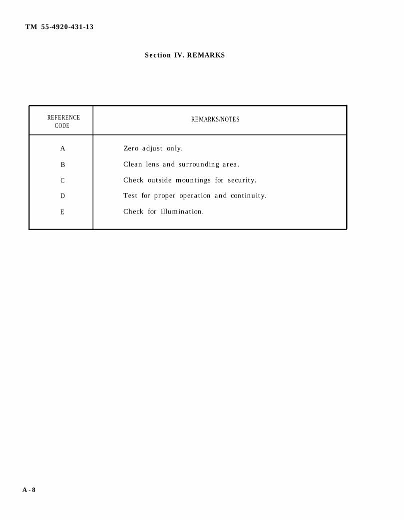
A-7. Remarks (Section IV). Remarks contained in column 6, with an alphabetical code,are listed to provide a ready reference to the definition of the remarks.
a. This Maintenance Allocation Chart (MAC) assigns maintenance functions in accordance with the ThreeLevels of Maintenance concept for army aircraft. These maintenance levels: Aviation Unit Maintenance(AVUM), Aviation Intermediate Maintenance (AVIM) and Depot Maintenance are depicted on the MAC as:
AVUM which corresponds to the O code in the Repair Parts and Special Tools List (RPSTL).
AVIM which corresponds to the F code in the Repair Parts and Special Tools List (RPSTL).
DEPOT which corresponds to the D code in the Repair Parts and Special Tools List (RPSTL).
b. The maintenance to be performed below depot and in the field is described as follows:
(1) Aviation Unit Maintenance (AVUM). AVUM activities will be staffed and equipped to perform highfrequency “On-Equipment” maintenance tasks required to retain or return equipment to a serviceablecondition. The maintenance capability of the AVUM will be governed by the MAC and limited by theamount and complexity of support equipment, facilities required, and number of spaces and criticalskills available. The range and quantity of authorized spare modules/components will be consistentwith the mobility requirements dictated by the air mobility concept. (Assignment of maintenance tasksto divisional company size aviation units will consider the overall maintenance capability of thedivision, the requirement to conserve personnel and equipment resources and air mobilityrequirements).
(a) Company Size Aviation Units. Perform those tasks which consist primarily of preventivemaintenance and maintenance repair and replacement functions associated with sustaining a highlevel of equipment operational readiness. Perform maintenance inspections and servicing to includedaily, intermediate, periodic and special inspections as authorized by the MAC or higherheadquarters. Identify the cause of equipment system malfunctions using applicable technicalmanual troubleshooting instructions. Built-In-Test Equipment (BITE), installed instruments, oreasy to use Test Measurement and Diagnostic Equipment (TMDE). Replace worn or damagedmodules/components which do not require complex adjustments or system alignments and whichcan be removed/installed with available skills, tools and equipment. Perform operational andcontinuity checks and make minor repairs. Perform servicing, functional adjustments, and minorrepair/replacement. Evacuate unserviceable modules/components and end items beyond the repaircapability of AVUM to the supporting AVIM.
(b) Less than Company Size Aviation Units. Aviation elements organic to brigade, group, battalionheadquarters and detachment size units are normally small and have less than ten aircraftassigned. Maintenance tasks performed by the aircraft crew chief or assigned aircraft repairmanwill normally be limited to preventive maintenance, inspections, servicing, spot painting, stopdrilling, minor adjustments module/component fault diagnosis and replacement of selectedmodules/components. Repair functions will normally be accomplished by the supportingAVIM unit.
Authorized maintenance includes replacement and repair of modules/components and end items which
maintenance support (Maintenance functions which are not conducive to sustaining air mobility will beassigned to depot maintenance). Performs all maintenance functions authorized to be done at AVUM.Repair of equipment for return to user will emphasize support or operational readiness requirements.
can) be accomplished efficiently with available skills, tools, and equipment. Establishes the DirectExchange (DX) program for AVUM units by repairing selected items for return to stock when suchrepairs cannot be accomplished at the AVUM level. Inspects, troubleshoots, tests, diagnoses, repairs,adjusts, calibrates, and aligns system modules/components. Module/component disassembly and repairwill support the DX program and will normally be limited to tasks requiring cleaning and thereplacement of seals, fittings and items of common hardware. Unserviceable reparablemodules/components and end items which are beyond the capability of AVIM to repair will beevacuated to Depot Maintenance. This level will perform special inspections which exceed AVUMcapability. Provides quick response maintenance support, on-the-job training, and technical assistancethrough the use of mobile maintenance contact teams. Maintains authorized operational readiness float.Provides collections and classification services for serviceable/unserviceable material. Operates acannibalization activity in accordance with AR 750-50. (The aircraft maintenance company within themaintenance battalion of a division will perform AVIM functions consistent with air mobilityrequirements and conservation of personnel and equipment resources. Additional intermediatemaintenance support will be provided by the supporting non-divisional AVIM unit).
B-2. USE OF THE MAINTENANCE ALLOCATION CHART.
a. The MAC assigns maintenance functions to the lowest level of maintenance based on past experience andthe following consideration:
(1) Skills available.
(2) Time required
(3) Tools and test equipment required and/or available.
b. Only the lowest level of maintenance authorized to perform a maintenance function is indicated. If thelowest level of maintenance cannot perform all tasks of any single maintenance function (e.g., test, repair), thenthe higher maintenance level(s) that can accomplish additional tasks will also be indicated.
c. A maintenance function assigned to a maintenance level will automatically be authorized to be performed atany higher maintenance level.
d. A maintenance function that cannot be performed at the assigned level of maintenance for any reason maybe evacuated to the next higher maintenance organization. Higher maintenance levels will perform themaintenance functions of lower maintenance levels when required or directed by the appropriate commander.
e. The assignment of a maintenance function will not be construed as authorization to carry the associatedrepair parts in stock. Authority to requisition, stock or otherwise secure necessary repair parts will be asspecified in the repair parts and special tools list appendix.
f. Normally there will be no deviation from the assigned level of maintenance. In cases of operationalnecessity, maintenance functions assigned to a maintenance level may, on a one-time basis and at the request ofthe lower maintenance level, be specifically authorized by the maintenance officer of the level of maintenance towhich the function is assigned. The special tools, equipment, etc. required by the lower level of maintenance toperform this function will be furnished by the maintenance level to which the function is assigned. This transferof a maintenance function to a lower maintenance level does not relieve the higher maintenance level of theresponsibility of the function. The higher level of maintenance will provide technical supervision and inspectionof the function being performed at the lower level.
g. Organizational through depot maintenance of the U.S. Army Electronics Command equipment will beperformed by designated U.S. Army Electronics Command personnel.
B-2 Change 1
TM 55-4920-431-13
h. Changes to the MAC till be based on continuing evaluation and analysis by responsible technical personneland on reports received from field activities.
B-3. DEFINITIONS.
a. Inspect. To detemine serviceability of an item by comparing its physical, mechanical and electricalcharacteristics with established standards.
b. Test. To verify serviceability and detect incipient failure by measuring the mechanical or electricalcharacteristics of an item and comparing those characteristics with prescribed standards.
c. Service. To clean, to preserve, to charge, and to add fuel, lubricants, cooling agents and air.
d. Adjust. To rectify to the extent necessary to bring into proper operating range.
e. Aline. To adjust specified variable elements of an item to bring to optimum performance.
f. Calibrate. To determine the corrections to be made in the readings of instruments or test equipment used inprecise measurement. Consists of the comparison of two instruments, one of which is a certified standard ofknown accuracy, to detect and adjust any discrepancy in the accuracy of the instrument or test equipment beingcompared with the certified standard.
g. Install. To set up for use in an operational environment such as an emplacement, site or vehicle.
h. Replace. To replace unserviceable items with serviceable assemblies, subassemblies or parts.
i. Repair. To restore an item to serviceable condition through correction of a specific failure or unserviceablecondition. This includes, but is not limited to, inspection, cleaning, preserving, adjusting, replacing, welding,riveting, and strengthening.
j. Overhaul. To restore an item to a completely serviceable condition as prescribed by maintenanceserviceability standards prepared and published for the specific item to be overhauled.
k. Rebuild. To restore an item to a standard as nearly as possible to the original or new condition inappearance, performance, and life expectancy. This is accomplished through the maintenance technique ofcomplete disassembly of the item, inspection of all parts or components, repair or replacement of worn orunserviceable elements (items) using original manufacturing tolerances and specifications, and subsequentreassembly of the item.
B-4. FUNCTIONAL GROUPS. Standard functional groupings are not considered feasible for aviation groundsupport equipment due to variation and complexity. Therefore variations to functional groupings may occur.
B-5. MAINTENANCE CATEGORIES AND WORK TIMES. The maintenance categories (levels) AVUM,AVIM, AND DEPOT are listed on the Maintenance Allocation Chart with individual columns that indicate thework times for maintenance functions at each maintenance level. Work time presentation such as 0.1 indicate theaverage time it requires a maintenance level to perform a specified maintenance function. If a work time has notbeen established, the columnar presentation shall indicate “-”. Maintenance levels higher than the level ofmaintenance indicated are authorized to perform the indicated function.
B-6. TOOLS AND TEST EQUIPMENT (Section III). Common tool sets (not individual tools), special tools, testand support equipment required to perform maintenance functions are listed alphabetically with a referencenumber to permit cross-referencing to column 5 in the MAC. In addition, the maintenance category authorized touse the device is listed along with the item National Stock Number (NSN) and, if applicable, the tool number toaid in identifying the tool/device.
B-7. REMARKS (Section IV). Remarks contained in column 6, with an alphabetical code, are listed to provide a ready reference to the definition of the remarks.
DISTRIBUTION:To be distributed in accordance with DA Form 12-31, Operator Maintenance
requirements for CH-47B/C & D aircraft.
This fine document...
Was brought to you by me:
Liberated Manuals -- free army and government manuals
Why do I do it? I am tired of sleazy CD-ROM sellers, who take publicly available information, slap “watermarks” and other junk on it, and sell it. Those masters of search engine manipulation make sure that their sites that sell free information, come up first in search engines. They did not create it... They did not even scan it... Why should they get your money? Why are not letting you give those free manuals to your friends?
I am setting this document FREE. This document was made by the US Government and is NOT protected by Copyright. Feel free to share, republish, sell and so on.
I am not asking you for donations, fees or handouts. If you can, please provide a link to liberatedmanuals.com, so that free manuals come up first in search engines:
<A HREF=http://www.liberatedmanuals.com/>Free Military and Government Manuals</A>