Operator’s Manual Torque Wrenches LP series WARNING To reduce risk of injury, everyone using, installing, repairing, maintaining, changing accessories on, or working near this tool must read and understand these instructions, as well as separately provided safety instructions part number 6159921190, before performing any such task. 6159921220 REV.04- 09/2017
Transcript
Operator’s ManualTorque Wrenches
LP series
WARNINGTo reduce risk of injury, everyone using, installing, repairing, maintaining, changing accessories on, or working near this tool must read and understand these instructions, as well as separately provided safety instructions part number 6159921190, before performing any such task.
6159921220 REV.04- 09/2017
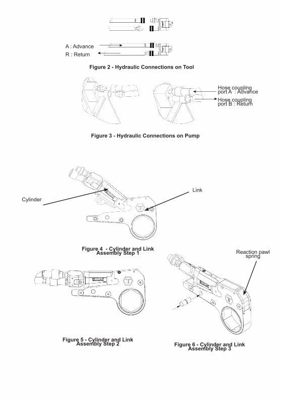
Figure 2 - Hydraulic Connections on Tool
Figure 3 - Hydraulic Connections on Pump
Figure 4 - Cylinder and Link Assembly Step 1
Figure 5 - Cylinder and Link Assembly Step 2 Figure 6 - Cylinder and Link
Assembly Step 3
A : AdvanceR : Return
Hose coupling port A : AdvanceHose coupling port B : Return
Link
Cylinder
Reaction pawl spring
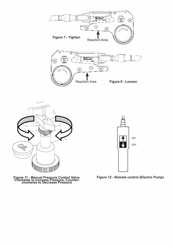
Figure 7 - Tighten
Figure 8 - Loosen
Figure 11 - Manual Pressure Control Valve, Clockwise to Increase Pressure, Counter-
clockwise to Decrease PressureFigure 12 - Remote control (Electric Pump)
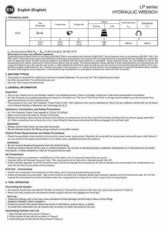
LpA Sound pressure dB(A), KpA = KWA = 3 dB Uncertainty. EN ISO 15744Declaration of noise and vibration statement Guaranteed sound power level Lw according to EN ISO 3744 in accordance with directive 2000/14/EC. Sound pressure level Lp according to EN ISO 11201, EN 500-4:2011.These declared values were obtained by laboratory type testing in accordance with the stated directive or standards and are suitable for comparison with the declared values of other machines tested in accordance with the same directive or standards. These declared values are not suitable for use in risk assessments and values measured in individual work places may be higher. The actual exposure values and risk of harm experienced by an individual user are unique and depend upon the way the user works, in what material the machine is used, as well as upon the exposure time and the physical condition of the user, and the condition of the machine. We, Chicago Pneumatic Tool Company LLC, cannot be held liable for the consequences of using the declared values, instead of values reflecting the actual exposure, in an individual risk assessment in a work place situation over which we have no control.
2. MACHINE TYPE(S)• This product is designed for installing and removing threaded fasteners. For use only with Titan hydraulic power packs.• No other use permitted. For professional use only.• Use with Titan hoses and accessories.
3. GENERAL INFORMATION
Inspection• Prior to use, inspect tool for any damage caused in the shipping process, if there is damage, contact your Titan sales representative immediately.• All Titan Products are supplied assembled and ready for immediate use. The use of Titan Power Pack is strongly recommended to provide the proper flow,
speed and accuracy of your hydraulic tools.• The accuracy of your new Titan Hydraulic Torque Tools is ±3%. Titan Hydraulic tools may be calibrated by Titan or by any calibration facility that can be traced
to the National Institute of Standards and Technology (N.I.S.T).
Hydraulics, Connections, and Safety Precautions• All Titan Hydraulic Torque Tools operate at 700 bar (10 000psi).• Make sure all hoses are rated for 700 bar (10 000 psi)• Before connecting or disconnecting hydraulic hoses release any pressure by turning the pump off and double checking that the pressure gauge reads Zero
(0). When connecting hose to the pump or tool, check fitting for cleanliness and ensure the fitting is engaged fully and hand tight.
WARNING:• Always ensure both hoses are securely connected.• Do not attempt to force the fitting using a wrench or any other means!
Electric Power Requirements and Safety Precautions• Check the specification plate located on the pump for proper power requirements. Operating the pump with the wrong power source will cause motor failure. If
you are unsure of the power requirements in your facility, seek a qualified electrician for guidance.
WARNING:• Do not remove the grounding prong from the electrical plug.• Electrical motors should not be used in volatile situations. Do not use an electrical pump in explosive atmospheres or in the presence of conduc-tive liquids. In these situations a Titan Air Pump should be used.
Air Connections• Please consult your compressor manufacturer’s air flow rating prior to using and pressurizing your pump.• Improper airflow will damage the pump motor. Titan recommends an air‐hose with a diameter greater than 3/4”.• A filter lubricator regulator unit (FLR) should be used. An FLR will regulate flow and pressure as well as lubricate and remove water from compressed air to
keep the air motor in your pump running properly.
FLR Unit - Connections• Consult your compressor manufacturer’s air flow rating prior to using and pressurizing your pump.• Airflow will damage the pump motor. Titan recommends an air‐hose with a diameter greater than lubricator regulator unit (FLR) should be used. An FLR will
regulate flow and pressure as well as lubricate water from compressed air to keep the air motor in your pump running properly.
4. TOOL OPERATION
Connecting the System• All hydraulic connections are rated for 700 Bar (10 000 psi). Connect the couplers on the hose, tool, and pump as shown in Figure 2.• Make sure male couplers are connected to female couplers and are fully engaged and hand tight.
Warning:• Tightening fittings with a tool may cause permanent thread damage and will lead to failure of the fitting.• ALWAYS CONNECT BOTH HOSES!!!!• Failure to connect the retract fitting may result in tool failure, serious injury, or death.• To avoid tool malfunction do not reverse the connector on either the pump or the tool.
Assembling Cylinder and Link1. Align Cylinder and Link as shown in Figure 4.2. Rotate cylinder till flush with link as shown in Figure 5.3. Insert mating pin till flush with the link as shown in Figure 6.
EN English (English) LP series
HYDRAULIC WRENCH
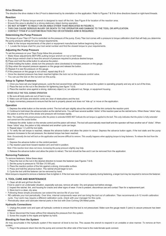
Drive DirectionThe direction the drive rotates in the LP‐tool is determined by its orientation on the application. Refer to Figures 7 & 8 for drive directions based on right‐hand threads.
Reaction• Every Titan LP‐Series torque wrench is designed to react off the link. See Figure 8 for location of the reaction area.• Ensure this area is abutted to a strong stationary object during operation.• DO NOT ATTEMPT TO REACT ON AN AREA OTHER THAN INDICATED IN FIGURE 8.• THIS CAN CAUSE SERIOUS INJURY OR DEATH TO THE OPERATOR AND DAMAGE TO THE TOOL OR APPLICATION.• CONTACT TITAN IF A CUSTOM REACTION PAD OR EXTENDED ARM IS REQUIRED.
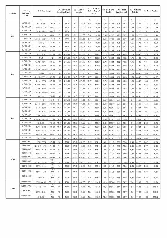
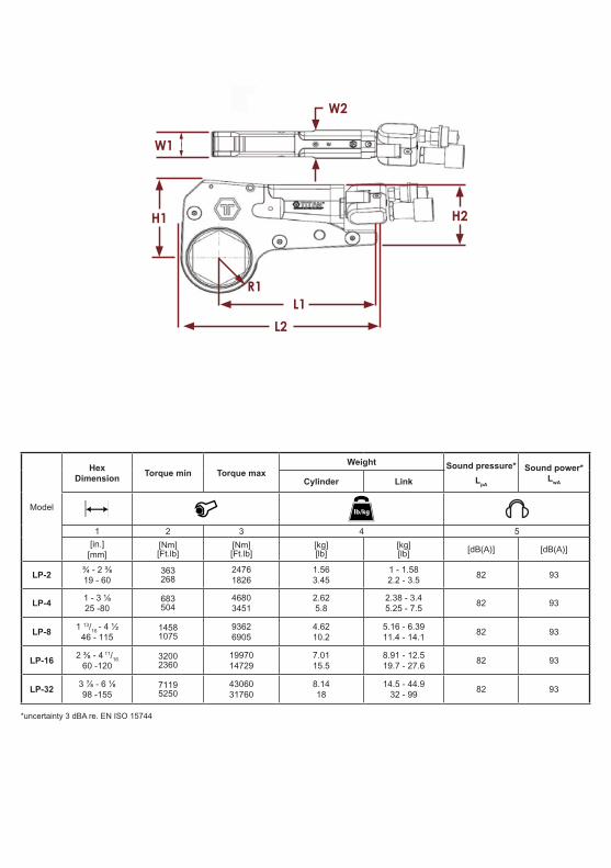
Determining the Pump PressureThe torque of your Titan LP‐Tool is controlled via the pressure of the pump. Every Titan tool comes with a pressure to torque calibration chart that will help you determine the pump pressure settings for your torque requirements.• Refer to the torque requirements of the plant or equipment manufacturer before beginning the job.• 1. Locate the torque chart for your tool serial number and find the closest torque to your requirements.
Adjusting the Pump PressureTo set the pressure on your Titan Pump follow this procedure:• Make these adjustments BEFORE putting torque wrench on nut or bolt head.A) See torque wrench chart to have the amount of pressure required to produce desired torque.B) Press and hold the white button to advance the piston.C) While holding the button, slowly turn the pressure valve (clockwise) to increase pressure on the gauge.D) Stop when the required pressure appears on the gauge and release the button.E) Repeat A to see the pressure on the gauge.F) If the pressure on the gauge is not correct, repeat step B to D• Once the desired pressure has been reached tighten the lock nut on the pressure control valve.• You can put the tool on the nut and run the pump.
Setup to Tighten Fasteners1. Once you have set your target pressure, cycle the tool several times without load to ensure the system is operating properly and any air is out of the lines.2. Place the tool on the nut in the direction for tightening (see figure 7 & 8).3. Place the reaction area against a strong, stationary object (i.e.) an adjacent nut, flange, or equipment housing.NEVER HOLD THE TOOL DURING OPERATION4. Be sure all body parts are out of harm’s way.5. Make sure all hoses and electric cords are clear of obstructions and the tool.6. Apply momentary pressure to ensure that the tool is properly placed and does not “ride up” or move on the application.
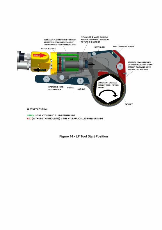
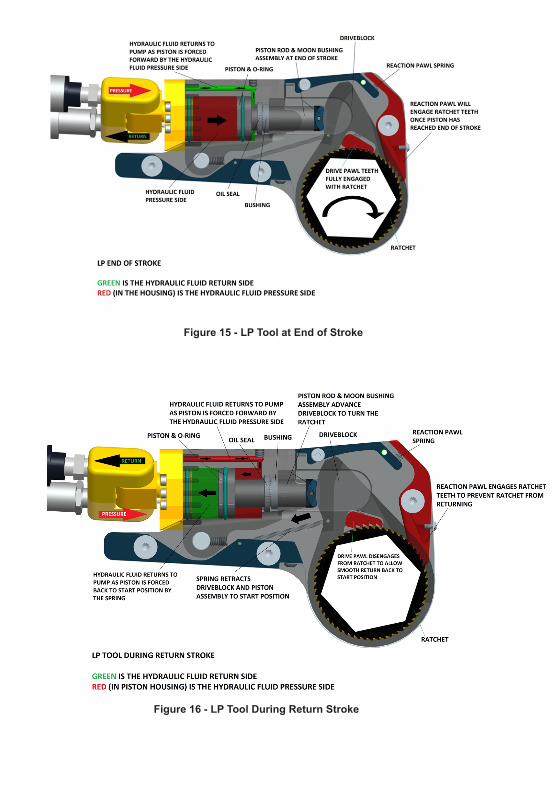
Operation1. Depress the white button on the remote control. The tool will spin slightly about the ratchet until the link contacts the reaction point.2. Continue to hold down the advance button as the ratchet turns. You will hear several audible “clicks” of the reaction pawl as the ratchet turns. When these “clicks” stop, the piston is at the end of the stroke and pressure will increase rapidly.Note: The reading of the preset pressure after the piston is extended DOES NOT indicate the set torque is applied to the bolt. This only indicates that the piston is fully extended and cannot turn the socket further.3. Release the white button on the remote control and the piston will retract. The tool will automatically reset itself and the operator will hear another set of “clicks”. When these “clicks” stop, the piston is fully retracted and another cycle can begin.4. Repeat steps 1‐3 until the tool stalls.5. To verify the set torque is reached, release the advance button and allow the piston to retract. Depress the advance button again, if the tool stalls and the pump pressure increases to the set pressure, the desired torque has been reached.Note: Occasionally the tool will lock on the application and become difficult to remove. This usually happens when applying torque to long fasteners. To release the tool from the fastener:1. Depress the advance button on the control pendant.2. Flip reaction pawl lever toward reaction arm and hold in position.Note: If the reaction lever does not move, increasing the pump pressure slightly may help.3. Release the advance button and allow the piston to retract. The tool should be free and it can be removed from the application
Removing FastenersTo remove fasteners, follow these steps:
1. Place the tool on the nut in the desired direction to loosen the fastener (see Figures 7 & 8).2. Set the pump to pressure to 700 Bar (10 000 psi).3. Place the reaction portion of the link against a strong, immovable surface.4. Press and hold the advance button. The ratchet should begin to turn.5. Cycle the tool until the fastener can be removed by hand.
More torque is required to remove a fastener than to tighten it. If the tool was near maximum capacity during fastening, a larger tool may be required to remove the fastener.
5. TOOL CARE AND MAINTENANCE1. Clean all dirt and grit from the linkIf tool is used in an underwater situation, especially sub‐sea, remove all water. Dry and grease tool before storage.2. Inspect the ratchet, link, and housing for cracks and other signs of wear. If one is present, discontinue use and contact Titan for a replacement part.3. Store tool in a clean, dry area.
• Following these simple procedures can extend the service life of your tool.• RE‐calibrate your tool periodically. Over time, internal components wear and can bring the tool out of calibration. Titan recommends a 6‐12 month calibration
cycle. Your work may require a different calibration cycle, check with your manager for this cycle.• Periodically clean and lubricate internal parts in the tool with Dow Corning GN Metal paste.
Hydraulic Connections1. Unplug the power cord and open all hydraulic controls to ensure that the tool is not pressurized. Make sure the gauge reads 0 (zero) to assure pressure has been released.2. Never disconnect the hoses without first releasing the pressure from the system.3. Screw the coupler to the nipple and tighten by hand.
Bleeding Air from the SystemAir may accumulate in the hydraulic system if the reservoir oil level is too low. This causes the wrench to respond in an unstable or slow manner. To remove air from system:
1. Plug in the pressure return line into the pump and connect the other side of the hose to the male‐female quick connect.
2. Run the pump for at least 5 minutes through several cycles.
Operating the PumpRead : Electric Hydraulic pump / Pneumatic Hydraulic Pumps - Operator's manual
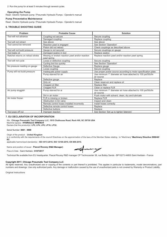
Problem Probable Cause SolutionTool will not advance Coupling not secure Secure coupling
Damaged coupling Replace couplingTool will not retract See above See aboveTool cannot be removed Reaction pawl is engaged See Section 'Operation'
Piston did not retract Check couplings as described aboveTool will not build pressure Gauge is not secured Secure couplings on gaugeTool leaks oil Damaged seal(s) in tool Replace seal(s)Ratchet returns on retract stroke Missing or broken reaction pawl and/or reaction
pawl springReplace reaction pawl and/or reaction pawl spring
Tool will not cycle Loose or defective coupling Secure couplingCycling tool too quickly See Section 'Operation'
No pressure reading on gauge Defective Gauge Replace gaugeLoose coupling Secure coupling
Pump will not build pressure Inadequate power supply Use proper power source according to motor specification plate.Pump starved for air Use minimum 1” diameter air hose attached to 100 psi/50cfm
air sourceDefective gauge ReplaceDirty oil Clean reservoir and replace oilClogged oil filter Replace filterClogged FLR Clean or replace FLR
Air pump sluggish Pump starved for ai Use minimum 1” diameter air hose attached to 100 psi/50cfm air source
Dirt in air motor Flush motor with solvent, clean, dry and lubricateAir motor frozen FLR is missing or broken Replace FLR
Obstruction in Air valve Inspect and cleanRemote control hoses installed incorrectly Install hoses correctlyDefective remote control hoses ReplaceDefective buttons Replace
Tool pops off nut Improper reaction See Section 'Set up to tighten fateners'
7. EU DECLARATION OF INCORPORATIONWe : Chicago Pneumatic Tool Company LLC, 1815 Clubhouse Road, Rock Hill, SC 29730 USA Machine type(s): HYDRAULIC WRENCHDeclare that the product(s): LP2, LP4, LP8, LP16, LP32.
Serial Number: 0001 - 9999
Origin of the product : United Kingdomis in conformity with the requirements of the council Directives on the approximation of the laws of the Member States relating : to “Machinery“ Machinery Directive 2006/42/EC applicable harmonised standard(s) : ISO 4413-2010, ISO 12100-2010, EN 809-2010.
Name and position of issuer : Pascal Roussy (R&D Manager)
Place & Date : Saint-Herblain, 31/07/2017
Technical file available from EU headquarter. Pascal Roussy R&D manager CP Technocenter 38, rue Bobby Sands - BP10273 44800 Saint Herblain - France
Copyright 2017, Chicago Pneumatic Tool Company LLC All rights reserved. Any unauthorized use or copying of the contents or part thereof is prohibited. This applies in particular to trademarks, model denominations, part numbers and drawings. Use only authorized parts. Any damage or malfunction caused by the use of unauthorized parts is not covered by Warranty or Product Liability.


![MOVING COIL ACTUATORS · 2 SMAC Product Overview Cylinder CAL12 Stroke [mm]; 10 Force [N]: 1.5 CAL36 Stroke [mm]: 15, 25, 50 Force [N]: 12 - 18 CAL75 Stroke [mm]: 15, 25, 50](https://static.documents.pub/doc/80x56/5f9e97e3d6481c332d3116ef/moving-coil-actuators-2-smac-product-overview-cylinder-cal12-stroke-mm-10-force.jpg)


![ElectriccylindersESBF,withspindledrivewithspindledrive Keyfeatures Ataglance ... BS Ballscrewspindle Size Stroke[mm] Spindlepitch [mm] Variant F Femalethread S1 ProtectionclassIP65](https://static.documents.pub/doc/80x56/5ac437547f8b9a220b8cabfc/electriccylindersesbf-withspindledrive-keyfeatures-ataglance-bs-ballscrewspindle.jpg)


![MOVING COIL ACTUATORS - DELTA EQUIPEMENT2 SMAC Product Overview Cylinder CAL12 Stroke [mm]; 10 Force [N]: 1.5 CAL36 Stroke [mm]: 15, 25, 50 Force [N]: 12 - 18 CAL75 Stroke [mm]: 15,](https://static.documents.pub/doc/80x56/5f9e97e3d6481c332d3116f2/moving-coil-actuators-delta-equipement-2-smac-product-overview-cylinder-cal12.jpg)