Operator's Manuam ® 10 in. COMPOUND MITER SAW Modem No. 137.212290 CAUTmON: Before using this Mker Saw, read this manual and follow all its Safety Rules and Operating Instructions o Safety mnstructions o mnstaliation o Operation o Maintenance o Parts List Customer Help Line 1 o800o843ol 682 Sears, Roebuck and Co., Hoffman Estates, IL 60179 USA Visit our Craftsman website: www.sears.com/craftsman Part No. 137212290001
Transcript
Operator's Manuam
®
10 in. COMPOUND MITER SAW
Modem No. 137.212290
CAUTmON:
Before using this Mker Saw,read this manual and follow
all its Safety Rules and
Operating Instructions
o Safety mnstructionso mnstaliation
o Operationo Maintenance
o Parts List
Customer Help Line1 o800o843ol 682
Sears, Roebuck and Co., Hoffman Estates, IL 60179 USAVisit our Craftsman website: www.sears.com/craftsman
Part No. 137212290001
ONE-YEAR FULL WARRANTY ON CRAFTSMAN TOOLIf this Craftsman tool fails due to a defect in material or workmanship within one year from the date of purchase,CALL 1-800-4-MY-HOME ®TO ARRANGE FOR FREE REPAIR.
If this tool is used for commercial or rental purposes, this warranty will apply for only ninety days from the date ofpurchase. This warranty applies only while this tool is in the United States.This warranty gives you specific legal rights, and you may also have other rights, which vary, from state to state.
Some dust created by power sanding, sawing, grinding, drilling and other construction activities contains chemicalsknown to cause cancer, birth defects or other reproductive harm. Some examples of these chemicals are:
, Lead from lead=based paints
CrystaI!ine silica from bricks, cement and other masonry productsArsenic and chromium from chemically treated lumber
Your risk from these exposures varies, depending on how often you do this type of work. To reduce your exposure to
these chemicals, work in a well ventilated area and work with approved safety equipment such as dust masks that arespecially designed to filter out microscopic particle&
MOTOR
Power Source .......................... 120V AC, 60Hz, 15 Amp Beve! 45° L .............................. 1=9/16 in. x 5=1/2 in.Arbor Shaft Size ...................... 5/8 in. 45 ° Miter and 45° Bevel .......... 1=9/16 in. x 3=1/2 in.
Cutting Capacity:Crosscut .................................. 2=5/8 in. x 5=1/2 in.Miter 45° R & L ........................ 2=5/8 in. x 3=1/2 in.
1_, WARNING I
To avoid electrical hazards, fire hazards or damage to the tool, use proper circuit protection°This tool is wired at the factory for 110_120 Vott operation, it must be connected to a 110_120 Volt / 15 Amperetime delay fuse or circuit breaker. To avoid shock or fire, reptace power cord immediately if it is worn, cut or
damaged in any way. Before using your too!, it is critical that you read and understand these safety rules.Failure to follow these rules could result in serious injury to you or damage to the tool
GENERAL SAFETY mNSTRUCTmONS
BEFORE USmNG THIS POWER TOOL
Safety is a combination of common sense, staying alertand knowing how to use your power tool.
l,&WARNINGnTo avoid mistakes that could cause serious injury, do notplug the too! in unti! you have read and understood thefollowing.
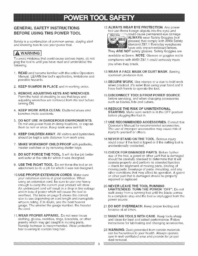
12.ALWAYS WEAR EYE PROTECTION Any powertoo! can throw foreign objects into the eyes andw_ _o_. could cause permanent eye damage_
ALWAYS wear Safety Goggles (notglasses) that comply with ANSI Safetystandard Z87.1 Everyday eyeglasseshave only impact-resistant lenses.
They ARE NOT safety glasses. Safety Goggles areavailable at Sears. NOTE: Glasses or goggles not in
compliance with ANSI Z87.1 could seriously injureyou when they break.
1. READ and become fami{iar with the entire OperatorsManual. LEARN the tool's application, limitations andpossible hazards.
2. KEEP GUARDS tN PLACE and in working order.
3. REMOVE ADJUSTING KEYS AND WRENCHES.Form the habit of checking to see that keys andadjusting wrenches are removed from the tool beforeturning ON.
4. KEEP WORK AREA CLEAN Cluttered areas andbenches invite accidents.
5. DO NOT USE iN DANGEROUS ENVIRONMENTS.Do not use power tools in damp locations, or exposethem to rain or snow. Keep work area well liL
6. KEEP CHILDREN AWAY. All visitors and bystandersshould be kept a safe distance from work area.
7. MAKE WORKSHOP CHILD PROOF with padlocks,master switches or by removing starter keys.
8. DO NOT FORCE THE TOOL. It wil! do the job betterand safer at the rate for which it was designed.
9. USE THE RIGHT TOOL. Do not force the too! or anattachment to do a job for which it was not designed.
10.USE PROPER EXTENSION CORDS. Make sureyour extension cord is in good condition. Whenusing an extension cord, be sure to use one heavyenough to carry the current your product will draw.An undersized cord win result in a drop in line voltageand in loss of power which wil! cause the tool tooverheaL The table on page 5 shows the correctsize to use depending on cord length and nameplateampere rating, if in doubt, use the next heaviergauge. The smaller the gauge number, the heavierthe cord.
1&WEAR A FACE MASK OR DUST MASK Sawingoperation produces dusL
14SECURE WORK. Use clamps or a vise to hold workwhen practical. It's safer than using your hand and itfrees both hands to operate the tool
15DISCONNECT TOOLS FROM POWER SOURCEbefore servicing, and when changing accessoriessuch as blades, bits and cutters.
16REDUCE THE RiSK OF UNINTENTIONALSTARTING. Make sure switch is in the OFF positionbefore plugging the too! in.
17.USE RECOMMENDED ACCESSORIES. Consutt thisOperator's Manual for recommended accessories.The use of improper accessories may cause risk ofinjury to yourself or others.
18NEVER STAND ON THE TOOL. Serious injurycould occur if the too! is tipped or if the cutting tool isunintentionally contacted_
1&CHECK FOR DAMAGED PARTS. Before furtheruse of the tool, a guard or other part that is damagedshould be carefully checked to determine that it willoperate properly and perform its intended function= check for alignment of moving parts, binding ofmoving parts, breakage of parts, mounting, and anyother conditions that may affect its operation. A guardor other part that is damaged should be properlyrepaired or replaced.
20NEVER LEAVE THE TOOL RUNNINGUNATTENDED. TURN THE POWER "OFF". Do notwalk away from a running tool until the blade comesto a complete stop and the tool is unplugged from thepowe r sou roe.
21 DO NOT OVERREACH Keep proper footing andbalance at al! times.
11 .WEAR PROPER APPAREL Do not wear looseclothing, gloves, neckties, rings, bracelets, or otherjewelry which may get caught in moving parts.Nonslip footwear is recommended. Wear protectivehair covering to contain long hair.
22.MA_NTAIN TOOLS W_TN CARE. Keep tools sharpand clean for best and safest performance. Followinstructions for lubricating and changing accessories.
2&WARNING: Dust generated from certain materialscan be hazardous to your health. Always operatesaw in well-ventilated area and provide for properdust removal.
SPECiFiC SAFETY mNSTRUCTmONS FOR
THiS COMPOUND MINTER SAW
1. USE ONLY CROSS-CUTTiNG SAW BLADES.When using carbide tipped blades, make sure theyhave a negative hook angle.IMPORTANT: DO NOT USE THIN KERF BLADES-they can deflect and contact guard and can causepossible injury to the operator.
2. DO NOT operate the miter saw until it is completelyassembled and installed according to theseinstructions.
3. tF YOU ARE NOT thoroughly familiar with theoperation of miter saws, seek guidance from yoursupervisor, instructor, or other qualified person.
4. ALWAYS hold the work firmly against the fence andtable. DO NOT perform any operation free hand (useclamp wherever possible).
5. KEEP BANDS out of the path of the saw blade. Ifthe workpiece you are cutting would cause yourhands to be within 6-3/4 inches of the saw blade, theworkpiece should be clamped in place before makingthe cuL
6. BE SURE the blade is sharp runs freely and is free ofvibration.
7. ALLOW the motor to come up to ful! speed beforestarting a cut.
8. KEEP THE MOTOR AIR SLOTS OLEAN and free ofchips or dust.
9. ALWAYS MAKE SURE all handles are tight beforecutting, even if the table is positioned in one of thepositive stops.
10.BE SURE both the blade and the co!lar are cleanand the arbor bolt is tightened securely.
11.USE only blade collars specified for your saw.
12.NEVER use blades larger in diameter than 10 inches.
13.NEVER apply lubricants to the blade when it isrunning.
14.ALWAYS check the blade for cracks or damagebefore operation. Replace a cracked or damagedblade immediately.
15.NEVER use blades recommended for operation atless than 4800 RPM.
1&ALWAYS keep the blade guards in place and use atal! times.
17NEVER reach around the saw blade.
18MAKE SURE the blade is not contacting theworkpiece before the switch is turned ON.
19.IMPORTANT: After completing the cut, release thetrigger and wait for the blade to stop before returningthe saw to the raised position.
20MAKE SURE the blade has come to a complete stopbefore removing or securing the workpiece, changingthe workpiece angle, or changing the angle of theblade.
21 .NEVER cut metals or masonry products with thistool. This miter saw is designed for use on wood andwood-like products.
22NEVER cut small pieces. If the workpiece being cutwould cause your hand or fingers to be within 6-3/4inches of the saw blade the workpiece is too small
2&PROVIDE adequate support to the sides of the sawtable for long work pieces.
24NEVER use the miter saw in an area with flammableliquids or gases.
25NEVER use solvents to clean plastic parts. Solventscould possibly dissolve or otherwise damage thematerial
26SHUT OFF the power before servicing or adjustingthe tool
27DISCONNECT the saw from the power source andclean the machine when finished using.
28MAKE SURE the work area is clean before leavingthe machine.
29SHOULD any part of your miter saw be missing,damaged, or fail in any way, or any electricalcomponent fail to perform properly, lock the switchand remove the plug from the power supply outleLReplace missing, damaged, or failed parts beforeresuming operation.
POWER SUPPLY AND MOTOR SPECIFICATIONSThe AC motor used in this saw is a universal,nonreversible type. See "MOTOR" in the "PRODUCTSPECIFICATIONS" section on page 2.
[A WARNING]
To avoid electrical hazards, fire hazards, or damage tothe too!, use proper circuit protection. Your saw is wiredat the factory for 120V operation. Connect to a 120V,15 Amp circuit and use a 15 amp. time delay fuse orcircuit breaker. To avoid shock or fire, if power cord isworn or cut, or damaged in any way, have it replacedimmediately.
ELECTRICAL REQUREMENTS - cont'dDOUBLE iNSULATEDThe power tool is double insulated to provide a doublethickness of insulation between you and tool's electricalsystem. All exposed metal parts are isolated fromthe internal metal motor components with protectinginsulation.
Replacement parts = When servicing use only identicalreplacement parts.
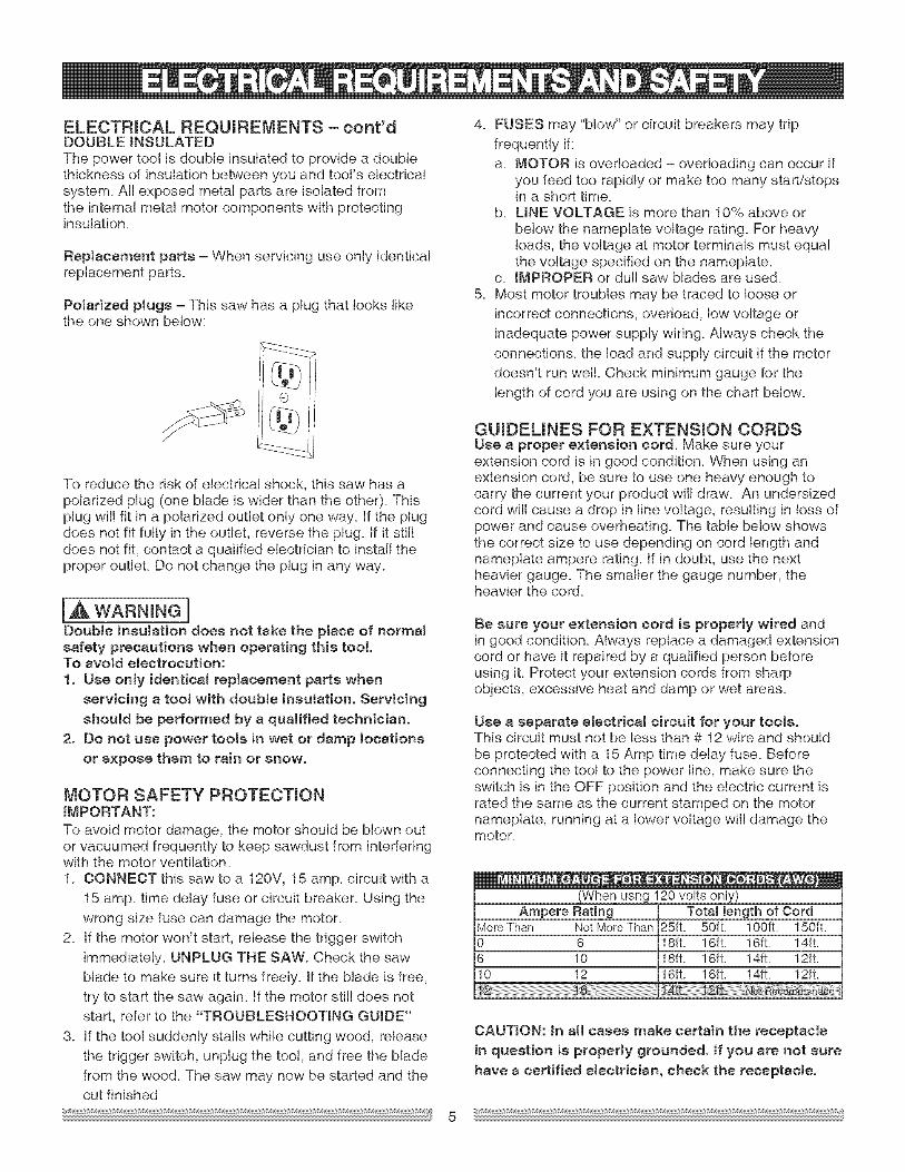
Polarized plugs = This saw has a plug that looks likethe one shown below:
To reduce the risk of electrical shock, this saw has apolarized plug (one blade is wider than the other). Thisplug wilt fit in a polarized outlet only one way. If the ptugdoes not fit fully in the outlet, reverse the plug. If it stilldoes not fit, contact a qualified electrician to install theproper outlet. Do not change the plug in any way.
la,WARNINGnDouble insulation does not take the place of normalsafety precautions when operating this tool.To avoid electrocution:1. Use only identical replacement parts when
servicing a toot with double insulation. Servicing
should be performed by a qualified technician.2. Do not use power tools in wet or damp locations
or expose them to rain or snow.
MOTOR SAFETY PROTECTmONiMPORTANT:To avoid motor damage, the motor should be blown outor vacuumed frequently to keep sawdust from interferingwith the motor ventilation.1. CONNECT this saw to a 120V, 15 amp. circuit with a
15 amp. time delay fuse or circuit breaker. Using the
wrong size fuse can damage the motor.2. If the motor won't start, release the trigger switch
immediately. UNPLUG THE SAW. Check the sawblade to make sure it turns freely, if the blade is free,try to start the saw again. If the motor still does notstart, refer to the "TROUBLESHOOTING GUIDE"
3. If the too! suddenly statls while cutting wood, releasethe trigger switch, unplug the tool, and free the bladefrom the wood. The saw may now be started and thecut finished
4_ FUSES may "blow" or circuit breakers may tripfrequently if:a. MOTOR is overloaded = overloading can occur if
you feed too rapidly or make too many start/stopsin a short time.
b. LiNE VOLTAGE is more than 10% above orbelow the nameplate voltage rating. For heavyloads, the voltage at motor terminals must equalthe voltage specified on the nameplate.
c. iMPROPER or duJl saw blades are used.5. Most motor troubles may be traced to loose or
incorrect connections, overload, low voltage orinadequate power supply wiring. Always check theconnections, the load and supply circuit if the motor
doesn't run well. Check minimum gauge for thelength of cord you are using on the chart below.
GUmDEUNES FOR EXTENSmON CORDSUse a proper e×tenaion cord. Make sure yourextension cord is in good condition. When using anextension cord, be sure to use one heavy enough tocarry the current your product will draw. An undersizedcord will cause a drop in line voltage, resulting in loss ofpower and cause overheating. The table below showsthe correct size to use depending on cord length andnameplate ampere rating. If in doubt, use the nextheavier gauge. The smaller the gauge number, theheavier the cord.
Be sure your extension cord is properly wired andin good condition. Always replace a damaged extensioncord or have it repaired by a qualified person beforeusing it. Protect your extension cords from sharpobjects, excessive heat and damp or wet areas.
Use a separate electrical circuit for your tools.This circuit must not be less than # 12 wire and shouldbe protected with a 15 Amp time delay fuse. Beforeconnecting the tool to the power line, make sure theswitch is in the OFF position and the electric current israted the same as the current stamped on the motornameplate, running at a lower voltage will damage themotor.
(When usng 120 volts only)Ampere Rating Total length of Cord
in question is properly grounded. If you are not sure
have a certified eJectrieian, check the receptacle.
RECOMMENDED ACCESSORIES
IA WARNING IUse only accessories recommended for this
miter saw. Foltow instructions that accompanyaccessories. Use of improper accessories maycause hazards.
, The usa of any cutting too! except 10 inch saw
blades which meet the requirements underrecommended accessories is prohibited. Donot use accessories such as shaper cutters or
dado sets. Ferrous metal cutting and the use of
abrasive wheels is prohibited,, Do not attempt to modify this toot or create
accessories not recommended for use with
this tool. Any such alteration or modification ismisuse and could result in a hazardous condition
leading to possible serious injury.
ACCESSORmES
Visit your Sears Hardware Department or see theSears Power and Hand Tool Catalog to purchaserecommended accessories for this power tool
IA WARNINGITo avoid the risk of personal injury, do not
modify this power tool or use accessories notrecommended by Sears.
IA WARNING I
Read warnings and conditions on your CARBIDETIPPED SAW BLADE. Do not operate the sawwithout the proper saw blade guard in place.
Carbide is a very hard but brittle material Careshould be taken while mounting, using, and storingcarbide tipped blades to prevent accidental damage.
Slight shocks, such as striking the tip whilehandling, can seriously damage the blade. Foreignobjects in the workpiece, such as wire or nails, can
also cause tips to crack or break off. Before using,always visually examine the blade and tips for bentblade, cracks, breakage, missing or loose tips, orother damage. Do not use if damage is suspected.
Failure to heed safety instructions and warnings canresult in serious bodily injury.
.)
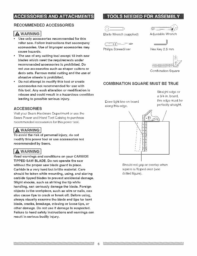
Blade Wrench (supplied) Adjustable Wrench
Philips Screwdriver Hex Key 2_5 mm
Combination Square
COMBINATmON SQUARE MUST BE TRUE
Draw light line on boardalong this edge.
Straight edge ora 3/4 in. board,this edge must be
perfectly straighL
\, /L
!
Should not gap or overlap when
square is flipped over (seedotted figure).
UNPACKING YOUR MINTER SAW
IA WARNINGnTo avoid injury from unexpected starting or
electrical shock, do not plug the power cord into asource of power during unpacking and assembly.This cord must remain unplugged whenever you are
working on the saw.
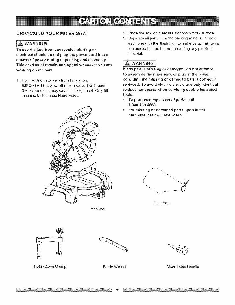
1. Remove the miter saw from the carton.
iMPORTANT: Do not lift miter saw by the Trigger
Switch handle, it may cause misalignmenL Only liftmachine by the base Hand Hold&
2. Place the saw on a secure stationary work surface.3. Separate ali parts from the packing material. Check
each one with the illustration to make certain all items
are accounted for, before discarding any packingmaterial
[A& WARNING]if any part is missing or damaged, do not attemptto assemble the miter saw, or plug in the power
cord until the missing or damaged part is correctlyreplaced. To avoid etectric shock, use only identicalreplacement parts when servicing douNe insulatedtools.
To purchase replacement parts, call1-800-469-4683.
, For missing or damaged parts upon initiat
purchase, caH 1-800-843-1882.
Machine
Dust Bag
Hold =Down Clamp Blade Wrench Miter Table Handle
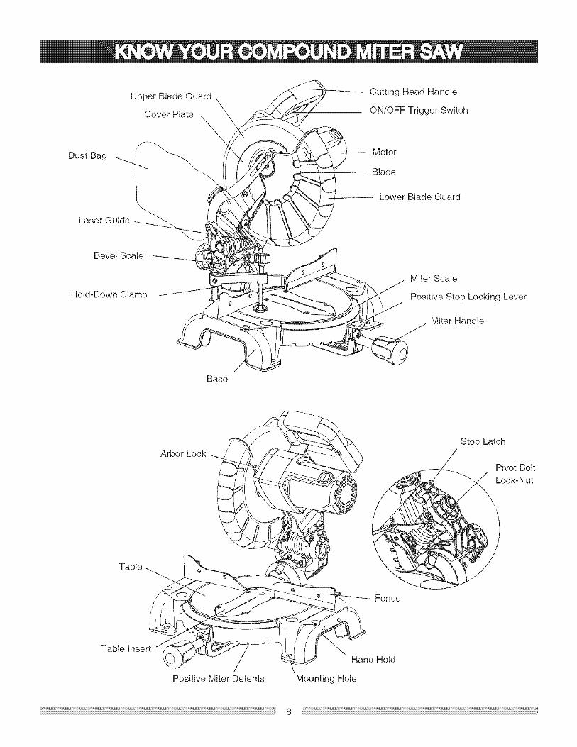
UpperBladeGuardCoverPlate
DustBag
LaserGuide
BevelScale
Hold-DownClamp
CuttingHeadHandle
ON/OFFTriggerSwitch
Motor
Blade
LowerBladeGuard
MiterScale
PositiveStopLockingLever
MiterHandle
Base
ArborLock
\
Fence
Stop Latch
Pivot BoltLock-Nut
Table Insert
/Positive Miter Detents
Hand Hold
Mounting Hole
COMPOUND MINTER SAW TERMS
ARBOR LOCK = Allows the user to keep the bladefrom rotating while tightening or loosening the arbor boltduring blade replacement or removal
BASE = Supports the table, holds accessories andallows for workbench or leg set mounting.
BEVEL LOCKING HANDLE = Locks the miter saw at a
desired bevel angle.
WARNING LABELS = Read and understand for yourown safety. Make sure al! labels are present on machineand legible.
WRENCH STORAGE = Convenient storage to preventmisplacing the blade wrench.
WOODWORKING TERMS
ARBOR = The shaft on which a blade is mounted.
BEVEL SCALE = To measure the bevel angle of thesaw blade 0° to 45° lefL
COVER PLATE SCREW = Loosen this screw and rotate
the plate for access to the blade arbor boll
FENCE = Helps to keep the workpiece from movingwhen sawing. Scaled to assist with accurate cutting.
HAND HOLD = For moving the saw when unplugged.
ON/OFF TRIGGER SWITCH = To start the tool,squeeze the trigger. Release the trigger to turn off themiter saw.
LOWER BLADE GUARD = Helps protect your handsfrom the blade in the raised position, it retracts as theblade is lowered.
MITER HANDLE = Use to lock and unlock the miter
table, and to rotate the saw to a right or left cuttingposition.
MITER SCALE = Measures the miter angle 0° to 45 ° leftand righL
POSJTtVE STOP LOCKING LEVER = With the miter
handle, locks the miter saw at a preset positive stop forthe desired miter angle.
MOUNTING HOLES = To mount the miter saw to astable surface.
STOP LATCH = Locks the miter saw in the lowered
position for compact storage and transportation.
SWITCH HANDLE = The cutting head handle containsthe trigger switch. The blade is lowered into theworkpiece by pushing down on the handle. The saw willreturn to its upright position when the handle is released.
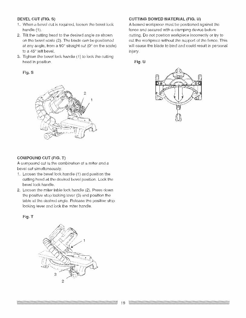
BEVEL CUT = An angle cut made through the face ofthe workpiece.
COMPOUND CUT = A simultaneous bevel and mitercut+
CROSS CUT = A cut made across the width of the
workpiece.
FREEHAND = Performing a cut without using a fence(guide), hold down or other proper device to prevent theworkpiece from twisting during the cutting operation+
GUM = A sticky s-ap from wood products+
HEEL = Misalignment of the blade.
KERF = The amount of material removed by blade cut.
MITER CUT = An angle cut made across the width ofthe workpiece.
RESIN = A sticky sap that has hardened+
REVOLUTIONS PER MINUTE (RPM} = The number ofturns completed by a spinning object in one minute.
SAW BLADE PATH = The area of the workpiece ortable top directly in line with the travel of the blade or thepart of the workpiece which will be cuL
SET = The distance between two saw blade tips, bentoutward in opposite directions to each other. The furtherapart the tips are, the greater the seL
WORKPtECE = The item being cuL The surfaces of aworkpiece are commonly referred to as faces, ends, andedges.
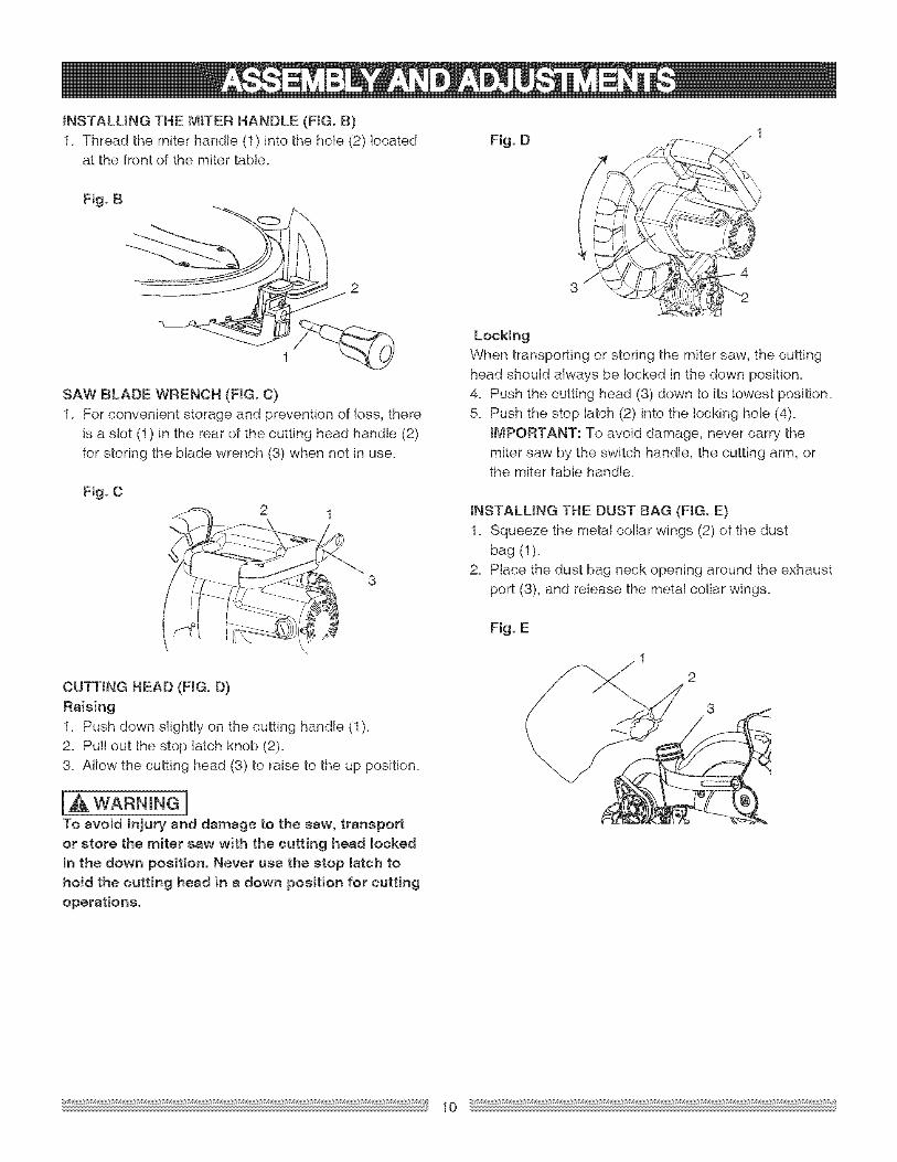
is a slot (1) in the rear of the cutting head handle (2)for storing the blade wrench (3) when not in use.
Fig. C
CUTTING HEAD (FIG. D)Raising
1. Push down slightly on the cutting handle (1).2. Pull out the stop latch knob (2).3. Allow the cutting head (3) to raise to the up position.
l,&WARNINGnTo avoid injury and damage to the saw, transport
or store the miter saw with the cutting head lockedin the down position. Never use the stop latch tohold the cutting head in a down position for cuttingoperations.
Locking
When transporting or storing the miter saw, the cuttinghead should always be locked in the down position.4. Push the cutting head (3) down to its lowest position.5. Push the stop latch (2) into the locking hole (4).
IMPORTANT: To avoid damage, never carry themiter saw by the switch handle, the cutting arm, orthe miter table handle.
iNSTALLiNG THE DUST BAG (FIG. E)1_ Squeeze the metal collar wings (2) of the dust
bag (1)_2_ Place the dust bag neck opening around the exhaust
port (3), and release the metal collar wings.
Fig. E
10
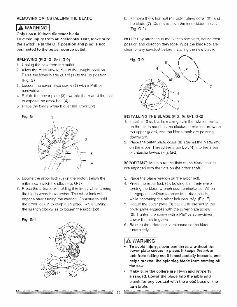
REMOVINGORINSTALLINGTHEBLADE
IA WARNINGnOnly use a 104rich diameter blade.To avoid injury from an accidental start, make sure
the switch is in the OFF position and plug is notconnected to the power source outlet.
8. Remove the arbor bolt (4), outer blade collar (6), and
the blade (7). Do not remove the inner blade collar.(Fig. G=2)
NOTE: Pay attention to the pieces removed, noting their
position and direction they face. Wipe the blade collarsclean of any sawdust before installing the new blade.
REMOWNG (FIG. G, G-l, G-2}1. Unplug the saw from the outleL2. Allow the miter saw to rise to the upright position.
Raise the lower blade guard (1) to the up position.
(Fig. G)3. Loosen the cover plate screw (2) with a Phillips
screwdriver.
4. Rotate the cover plate (3) towards the rear of the toolto expose the arbor bolt (4).
5. Place the blade wrench over the arbor bolt.
Fig. G 1
Fig. G-26
7
6
tNSTALUNG THE BLADE (FIG. G, G-I, G-2}1. install a 10 in. blade, making sure the rotation arrow
on the blade matches the clockwise rotation arrow on
the upper guard, and the blade teeth are pointingdownward.
2. Place the outer blade collar (6) against the blade andon the arbor. Thread the arbor bolt (4) into the arborcounterclockwise. (Fig. G-2)
IMPORTANT: Make sure the fiats of the blade collars
are engaged with the fiats on the arbor shall
6. Locate the arbor lock (5) on the motor, below themiter saw switch handle. (Fig. G-1 )
7. Press the arbor lock, holding it in firmly while turningthe blade wrench clockwise. The arbor lock wi!l
engage after turning the wrench. Continue to holdthe arbor lock in to keep it engaged, while turningthe wrench clockwise to loosen the arbor boll
Fig. G-1
11
3. Place the blade wrench on the arbor boll
4. Press the arbor lock (5), holding it in firmly whileturning the blade wrench counterclockwise. When
it engages, continue to press the arbor lock in,while tightening the arbor bolt securely. (Fig. F)
5. Rotate the cover plate (3) back until the slot in thecover plate engages with the cover plate screw
(2). Tighten the screw with a Phillips screwdriver.Lower the blade guard.
6. Be sure the arbor lock is released so the blade
turns freely.
[,&wARN Ne], To avoid injury, never use the saw without the
cover plate secure in place. It keeps the arborbolt from falling out if it accidentally loosens, andhelps prevent the spinning blade from coming offthe saw.
Make sure the collars are clean and properlyarranged. Lower the blade into the table and
check for any contact with the metal base or theturn table.
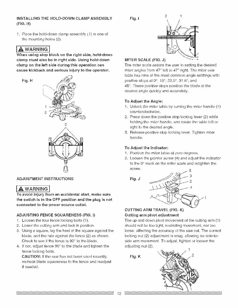
1_Placethehold=downclampassembly(1)in one ofthe mounting holes (2)_
IA WARN,NGnWhen using stop block on the right side, hold-down
clamp must also be in right side. Using hold-downclamp on the left side during this operation cancause kickback and serious injury to the operator.
Fig. H
1
2
2
ADJUSTMENT iNSTRUCTiONS
l_ WARN"NGnTo avoid injury from an accidental start, make surethe switch is in the OFF position and the plug is notconnected to the power source outlet.
ADJUSTING FENCE SQUARENESS (FIG. 01. Loosen the four fence locking bolts (1).2_ Lower the cutting arm and lock in position.
3_ Using a square, lay the heel of the square against theblade, and the rule against the fence (2) as shown.Check to see if the fence is 90° to the blade.
4_ If not, adjust fence 90° to the blade and tighten the
fence locking bolts.CAUTION: If the saw has not been used recently,recheck blade squareness to the fence and readjustif needed.
12
/
MITER SCALE (FIG. J)The miter scale assists the user in setting the desiredmiter angles from 47° left to 47 ° right. The miter sawtable has nine of the most common angle setttings with
positive stops at 0°, 15°, 22.5 °, 31 _6°, and45°. These positive stops position the blade at the
desired angle quickly and accurately.
To Adjust the Angle:
1. Unlock the miter table by turning the miter handle (1)counterc!ockwise.
2. Press down the positive stop locking lever (2) whileholding the miter handle, and rotate the table left or
right to the desired angle.3. Release positive stop locking lever. Tighten miter
handle.
To Adjust the Indicator:I. Position the miter table at zero degrees.2. Loosen the pointer screw (4) and adjust the indicator
to the 0° mark on the miter scale and retighten the
screw. 5
3Fig. J 2
CUTTING ARM TRAVEL (FIG. K)
Cutting arm pivot adjustmentThe up and down pivot movement of the cutting arm (1)should not be too tight, restricting movement, nor too
loose, affecting the accuracy of the saw cut. The correctlocking nut (2) adjustment is snug, allowing no side-to-side arm movement. To adjust, tighten or loosen theadjusting nut (2).
Fig. K
4
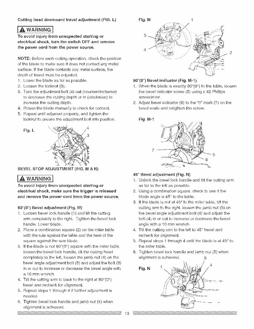
Cutting head downward travel adjustment (FIG. L)
IA WARNINGITo avoid injury from unexpected starting orelectrical shock, turn the switch OFF and remove
the power cord from the power source.
NOTE: Before each cutting operation, check the position
of the blade to make sure it does not contact any metalsurface. If the blade contacts any metal surface, thedepth of trave! must be adjusted.1. Lower the blade as far as possible.
2. Loosen the Iocknut (3).3. Turn the adjustment balt (4) out (counterclockwise)
to decrease the cutting depth or in (clockwise) toincrease the cutting depth.
4. Rotate the blade manually to check for contacL
5. Repeat until adjusted properly, and tighten the!ocknut to secure the adjustment bolt into position.
Fig. L4
3
BEVEL STOP ADJUSTMENT (FIG. M & N)
WARNINGITo avoid injury from unexpected starting or
electrical shock, make sure the trigger is releasedand remove the power cord from the power source.
90°(0 °) Bevel adjustment (Fig. M)1. Loosen bevel lock handle (1) and tilt the cutting
arm completely to the right. Tighten the bevel lockhandle. Lower blade.
2. Place a combination square (2) on the miter tablewith the rule against the table and the hee! of thesquare against the saw blade.
3. If the blade is not 900(0°) square with the miter table,loosen the bevel lock handle, tilt the cutting headcompletely to the left, loosen the jamb nut (4) on thebevel angle adjustment bait (3) and adjust the bolt (3)
in or out to increase or decrease the bevel angle witha 10 mm wrench.
4. Tilt the cutting arm to back to the right at 900(0°)
bevel and recheck for alignment.5. Repeat steps 1 through 4 if further adjustment is
needed.
6. Tighten bevel lock handle and jamb nut (4) whenalignment is achieved.
Fig. M
3
90°(0 °) Bevel indicator (Fig. M-I )
7 2
1. When the blade is exactly 900(0°) to the table, loosenthe bevel indicator screw (5) using a #2 Phi!lipsscrewdriver.
2. Adjust bevel indicator (6) to the "0" mark (7) on thebevel scale and retighten the screw.
Fig. M-l
45° Bevel adjustment (Fig. N)1. Unlock the beve! lock handle and tilt the cutting arm
as far to the left as possible.
2. Using a combination square, check to see if theblade angle is 45° to the table.
3. If the blade is not at 45 ° to the miter table, tilt the
cutting arm to the right, loosen the jamb nut (5) onthe bevel angle adjustment bolt (4) and adjust thebolt (4) in or out to increase or decrease the bevelangle with a 10 mm wrench.
4. Tilt the cutting arm to the left to 45° bevel andrecheck for alignment.
5. Repeat steps 1 through 4 until the blade is at 45° tothe miter table.
6. Tighten bevel lock handle and jamb nut (5) whenalignment is achieved.
Fig. N
5
13
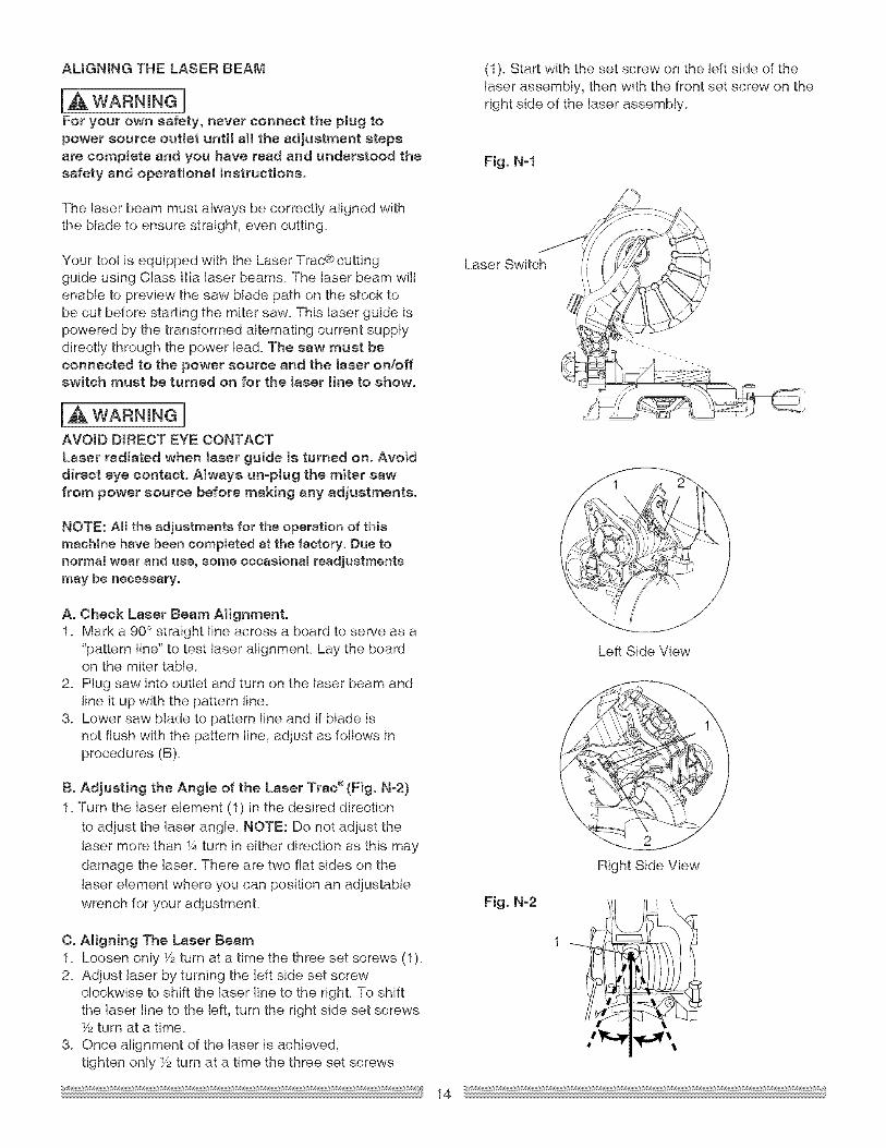
ALiGNiNGTHELASER BEAM
[A WARNING[For your own safety, never connect the plug topower source outlet unti[ all the adjustment stepsare complete and you have read and understood thesafety and operational instructions.
(1)_ Start with the set screw on the left side of thelaser assembly, then with the front set screw on theright side of the laser assembly.
Fig. N-1
The laser beam must always be correctly aligned withthe blade to ensure straight, even cutting.
Your tool is equipped with the Laser Trac® cuttingguide using Class ilia laser beams. The laser beam wilIenable to preview the saw blade path on the stock tobe cut before starting the miter saw. This laser guide ispowered by the transformed alternating current supplydirectly through the power lea& The saw must beconnected to the power source and the laser on/offswitch must be turned on for the laser line to show.
wARN NeIAVOID DIRECT EYE CONTACTLoser radiated when [aser guide is turned oil. Avoiddirect eye contact° Always un-piug the miter sawfrom power source before making any adjustments.
Laser " 'iSwitch i_
NOTE: All the adjustments for the operation of this
machine have been completed at the factory. Due to
normal wear and use, some occasional readjustments
may be necessary.
A. Check Loser Beam Alignment.1. Mark a 90° straight line across a board to serve as a
"pattern line" to test laser alignment. Lay the boardon the miter table.
2. Plug saw into outlet and turn on the laser beam andline it up with the pattern line.
3. Lower saw blade to pattern line and if blade isnot flush with the pattern line, adjust as follows inprocedures (B).
B. Adjusting the Angle of the Laser Trac®(Fig. N-2)
1. Turn the laser element (1) in the desired directionto adjust the laser angle. NOTE: Do not adjust thelaser more than _Aturn in either direction as this maydamage the laser. There are two flat sides on the
laser element where you can position an adjustablewrench for your adjustment.
C. Aligning The Laser Beam1. Loosen only Y2turn at a time the three set screws (1).2. Adjust laser by turning the left side set screw
clockwise to shift the laser line to the right. To shiftthe laser line to the left, turn the right side set screws_/2turn at a time.
3. Once alignment of the laser is achieved,tighten only Y2turn at a time the three set screws
Fig. N-2
Left Side View
Right Side View
14
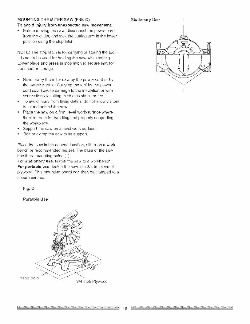
MOUNTING THE MITER SAW (FIG, O)To avoid injury from unexpected mew movement:
, Before moving the saw, disconnect the power cordfrom the outlet, and !ock the cutting arm in the lowerposition using the stop latch.
NOTE: The stop latch is for carrying or storing the tooLIt is not to be used for holding the saw while cutting.Lower blade and press in stop latch to secure saw for
transport or storage.
Never carry the miter saw by the power cord or bythe switch handle. Carrying the tool by the power
cord could cause damage to the insulation or wireconnections resulting in electric shock or fire.To avoid injury from flying debris, do not allow visitorsto stand behind the saw.
Place the saw on a firm, level work-surface wherethere is room for handling and properly supporting
the workpiece.Support the saw on a leve! work surface.Bolt or clamp the saw to its support.
Place the saw in the desired location, either on a work
bench or recommended leg seL The base of the sawhas three mounting holes (1).
For etetionery use, fasten the saw to a workbench.For po_ebte uee, fasten the saw to a 3/4 in. piece ofplywood. This mounting board can then be clamped to asecure surface.
Fig. 0
Portable Use
Stationery Uee
Hand Hold3/4 Inch Plywood
15
SAFETY mNSTRUCTmONS FOR BASmC SAWOPERATmON
BEFORE USING THE MITER SAW
IAWARNINGnTo avoid mistakes thatcould cause serious,
permanent injury, do not plug the toolin until thefollowing steps are completed:, Completely assemble and adjust the sew,
following the instructions. (ASSEMBLY ANDADJUSTMENTS)
, Learn the use and function of the ON/OFF switch,lock-off switch, upper and lower blade guards,stop latch, bevel lock handle, end cover platescrews.
, Review and understand all safety instructionsand operating procedures in this Operator'sManual (SAFETY & OPERATIONS)
, Reviewthe MAINTENANCE and
TROUBLESHOOTING GUIDE for your miter saw., To avoid injury or possible death from etectricaJ
shock:
Make sure your fingers do not touch the plug'smetal prongs when plugging or unplugging yourmiter saw. (ELECTRICAL REQUIREMENTS ANDSAFETY)
BEFORE EACH USE INSPECT YOUR SAW.
Disconnect the miter saw. To avoid injury fromaccidental starting, unplug the saw before anyadjustments, including set-up and blade changes.
, Compare the direction of rotation arrow on theguard to the direction arrow on the blade. Theblade teeth should always point downward st thefront of the saw.
, Tighten the arbor bolt., Tighten the cover plate screw., Check for damaged parts. Check for:
Alignment of moving psAsDamaged electric cordsBinding of moving parts
, Mounting holes, Function of arm return spring and lower
guard:Push the cutting arm all the way down, thenlet it rise until it stops. The lower guardshould fully ctose. Follow instructions inTROUBLESHOOTING GUIDE for adjustment ifnecessary.
, Other conditions that may affect the way themiter saw works.
Keep all guards in place, in working order andproper adjustment. If any part of this miter saw
is missing, bent damaged or broken in any way,or any electrical parts don't work, turn the sawoff and unplug it. Replace damaged, missing, ordefective parts before using the saw again.
, Maintain tools with care. Keep the miter sawclean for best and safest performance. Followinstructions for lubricating. Don't put lubricantson the blade while it's spinning.Remove adjusting wrench from the tool beforeturning it on.
, To avoid injury from jams, slips, or thrownpieces:
USE ONLY RECOMMENDED ACCESSORIES
Consult the ACCESSORIES and ATTACHMENTS
section of this Operators Manual forrecommended accessories. Follow the
instructions that come with the accessory. Theuse of improper accessories may cause risk ofinjury to persons.
, Choose the correct 10 inch diameter blade for the
material and the type of cutting you plan to do.Do not use thin kerf blades.
, Make sure the blade is sharp, undamaged and
properly aligned. With the saw unplugged, pushthe cutting arm sH the way down. Manually spinthe blade and check for clearance. Tilt the power-head to s 45° bevel and repeat the test.Make sure the btede and arbor collars are clean.
Make sure all clamps and !ocks ere tight andthere is no excessive play in any parts.
KEEPYOUR WORK AREA CLEAN
Cluttered areas and benches invite accidents.
[J& WARNING 1To avoid burns or other fire damage, never use themiter saw near fmsmmsble Hquids, vapors, or gases.
Plan ahead to protect your eyes, hands, face endesrs.
, Know your miter saw.Read and understand the Operator's Manual andlabels affixed to the tool Learn its applicationand limitations as wen as the specific potentialhazards peculiar to this tool. To avoid injury fromeccidentsJ contact with moving parts, don't dolayout, assembly, or setup work on the miter sawwhile any parts are moving.
, Avoid accidental startingMake sure the trigger switch is disengagedbefore plugging the miter saw into e power outtet.
16
PLANYOURWORK
Usetherighttool. Don'tforceatool orattachmentto doejob it was not designed to do.Use a different tool for any workpiece that can'tbe held in e solidly braced, fixed position.
CAUTION: This machine is not designed for cuttingmasonry, masonry products, ferrous metals (stee!,iron, and ironobesed metals°) Use this miter sew tocut only wood, wood-like products, or non-ferrousmetals. Other materiel may shatter, bind the blade,or create other dangers. Remove aH nails that maybe in the workpiece to prevent sparking that couldcause a fire. Remove dust beg when cutting non °ferrous metals.
DRESS FOR SAFETY
Any power tool can throw foreign objects into theeyes. This can result in permanent eye damage.Everyday eyeglasses have only impact resistentlenses and ere not safety glasses. Glasses orgoggtes not in compliance with ANSI Z87.1 couldseriously injure you when they break., Do not wear loose clothing, gloves, neckties or
jewelry (rings, watches)° They con get caught anddraw you into moving parts.
• Wear non-stip footwear., Tie back long heir.• Roll tong sleeves above the elbow.• Noise levels very widety. To avoid possible
hearing damage, wear ear plugs when using anymiter sew.
, For dusty operations,wear e dust mask alongwith safety goggles.
iNSPECTYOUR WORKPtECE
Make sure there ere no nails or foreign objects inthe part of the workpiece being cut.Plan your work to avoid smetl pieces that may bind,or that are too small to clamp and get a solidgrasp on.Plan the way you witl grasp the workpiece fromstarttofinish.Avoid awkward operationsend hand
positions.A sudden slipcould cause your fingersorhand to move into the blade.
DO NOT OVER-REACH
Keep good footing end balance. Keep your face
and body to one side, out of the line of e possiblekickback. NEVER stand in the line of the blade.
Make sure there ere no gaps between theworkpiece, fence end table that will let theworkpiece shift after it is cut.Keep the cut off piece free to move sidewaysafter it is cut off. Otherwise, it could get wedgedagainst the blade end thrown violently.Only the workpiece should be on the saws table.Secure work. Use ctemps or a vise to help hotdthe work when it's practical.
USE EXTRA CAUTION WITH LARGE OR ODDSHAPED WORKPIECES.
Use extra supports (tables, sawhorses, blocks,etc.) for workpieces large enough to tip.Never use another person as e substitute for etable extension, or as an additional support for eworkpiece that is longer or wider then the basicmiter saw table, or to help feed, support, or pullthe workpiece.Do not use this sew to cut sina!! pieces. If theworkpiece being cut would cause your hand orfingers to be within 6-3/4 inches of the saw bladethe workpiece is too smell. Keep hands endfingers out of the "no hands zone" area markedon the saws table.
• When cutting odd shaped workpieces, plan yourwork so it will not bind in the blade end causepossible injury. Molding, for example, must Hefiat or be hetd by e fixture or jig that will not let itmove when cut.Properly support round materia_ such as dowelrods, or tubing, which have e tendency to rollwhen cut, causing the blade to "bite".
[J_ WARNING 1
To avoid injury, follow all applicable safetyinstructions, when cutting non-ferrous metals:
Use only sew blades specifically recommendedfor non-ferrous meteJ cutting.Do not cut metal workpieces that must be handheld. C!amp workpieces securely.Cut non4errous metals onty if you are under thesupervision of an experienced person end thedust beg has been removed from the sew.
WHEN SAW iS RUNNING
[AWARNmNG]Do not eilow familiarity from frequent use of yourmiter sew to result in e careless mistake. A carelessfraction of e second is enough to cause e severeinjury.
Never cut freehand:Brace your workpiece firmly against the fenceend table stop so it will not rock or twist duringthe cut.
• Make sure there is no debris between theworkpiece and the table or fence.
Before cutting, if the sew makes an unfamiliar noiseor vibrates, stop immediately. Turn the sew OFF.Unplug the saw. Do not restart until finding andcorrecting the problem.
17
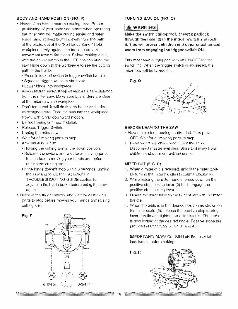
BODYANDBANDPOSITION(FIG.P}Neverplacehandsnearthecuttingarea.Properpositioningof yourbodyandhandswhenoperatingthemitersawwillmakecuttingeasierandsafer.Placehandatleast6=3/4in. away from the pathof the blade, out of the "No=Bands Zone." Bold
workpiece firmly against the fence to preventmovement toward the blade. Before making a cut,
with the power switch in the OFF position bring thesaw blade down to the workpiece to see the cuttingpath of the blade.
Press in lock=off switch in trigger switch handle.
Squeeze trigger switch to start saw.Lower blade into workpiece.
Keep children away. Keep all visitors a safe distancefrom the miter saw. Make sure bystanders are clearof the miter saw and workpiece.
Don't force too!. It will do the job better and safer atits designed rate. Feed the saw into the workpieceslowly with a firm downward motion.Before freeing jammed materia!.
Release Trigger Switch.Unplug the miter saw.Wait for atl moving parts to stop.
After finishing a cut:Holding the cutting arm in the down position.Release the switch, and wait for al! moving partsto stop before moving your hands and before
raising the cutting arm.If the blade doesn't stop within 6 seconds, unplugthe saw and follow the instructions inTROUBLESHOOTING GUIDE section for
adjusting the blade brake before using the sawagain.
, Release the trigger switch, and wait for a!l movingparts to stop before moving your hands and raisingcutting arm.
Fig. P
TURNING SAW ON (FIG. Q}
[A wARNINe]Make the switch child-proof. Insert e psdloekthrough the hole (2} in the trigger switch and lock
it. This will prevent children and other unauthorizedusers from engsging the trigger switch ON.
This miter saw is equipped with an ON/OFF triggerswitch (1). When the trigger switch is squeezed, themiter saw wil! be turned on.
Fig. Q2
1
BEFORE LEAWNG THE SAW
, Never leave too! running unattended. Turn powerOFF. Wait for alt moving parts to stop.
Make workshop child- proof. Lock the shop.Disconnect master switches. Store tool away fromchildren and other unqualified users.
MITER CUT (FIG. R)1. When s miter cut is required, unlock the miter table
by turning the miter handle (1) counterclockwise.
2. While holding the miter handle, press down on thepositive stop locking lever (2) to disengage thepositive stop locking lever.
3. Rotate the miter table to the right or left with the miterhandle.
4. When the table is in the desired position as shown onthe miter scale (3), release the positive stop locking
lever handle and tighten the miter handle. The tableis now locked at the desired angle. Positive stops areprovided at 0°,15 ° , 22.5 ° , 31.6 ° and 45 °.
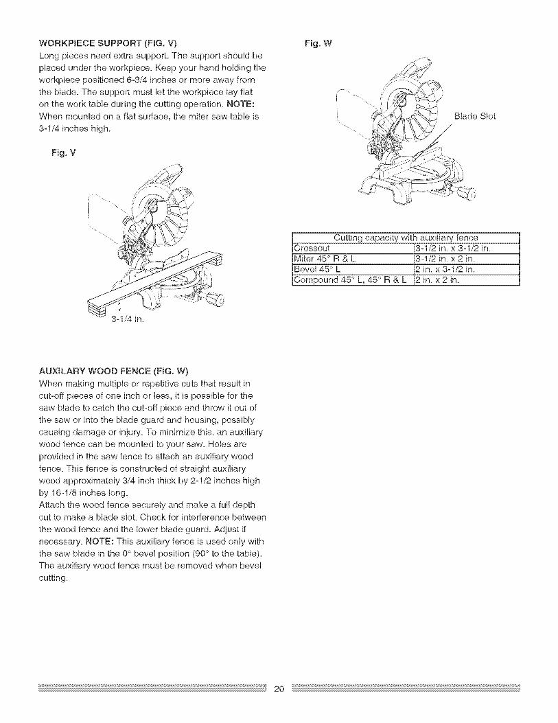
Cutting capacity with auxiliary fenceCrosscut 3ol/2 in. x 3-1/2 in.Miter 45° R & L 3-1/2 in. x 2 in.Bevel 45 ° L 2 in. x 3-1/2 in.Compound 45 °L,45 °R&L 2in. x2in.
3-1/4 in.
AUXILARY WOOD FENCE (FIG. W)
When making multiple or repetitive cuts that result incut-off pieces of one inch or less, it is possible for thesaw blade to catch the cut-off piece and throw it out of
the saw or into the blade guard and housing, possiblycausing damage or injury. To minimize this, an auxiliarywood fence can be mounted to your saw. Holes are
provided in the saw fence to attach an auxiliary woodfence. This fence is constructed of straight auxiliarywood approximately 3/4 inch thick by 2-1/2 inches highby 16-1/8 inches long.
Attach the wood fence securely and make a full depthcut to make a blade slot. Check for interference between
the wood fence and the lower blade guard. Adjust if
necessary. NOTE: This auxiliary fence is used only withthe saw blade in the 0° bevel position (90° to the table).The auxiliary wood fence must be removed when bevel
cutting.
2O
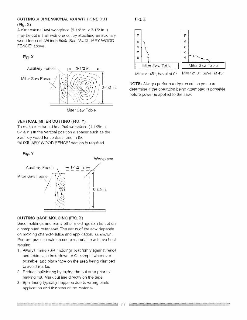
CUTTINGA BIJ"_ENSIONAL4X4WITHONECUT(Fig.X)A dimensional 4x4 workpiece (3ol/2 in_x 3ol/2 in_ )may be cut in half with one cut by attaching an auxiliarywood fence of 3/4 inch thick. See "AUXILIARY WOODFENCE" above.
Fig. X
Auxiliary Fence \ _ 3-1/2 in.
Miter Saw Fenc / ' _ __._ti
L I
Miter Saw Table
Fig. Z
FI
Miter Saw Table
Miter at 45 °, bevel at 0°
Fm
emnl
cm
el ---,Miter Sa_v Table
Miter at 0°, bevel at 45 °
NOTE: Always perform a dry run cut so you candetermine if the operation being attempted is possible
before power is applied to the saw.
VERTICAL MITER CUTTING (FIG. Y}To make a miter cut in a 2x4 workpiece (1-1/2in. x
3-1/2in.) in the vertical position a spacer such as theauxiliary wood fence described in the"AUXILIARY WOOD FENCE" section is required.
Fig. Y
Auxiliary Fenc_b,_
Miter Saw Fen_ I i
Workpiece
1ol/2 in. _
3ol/2 in_
1
CUTTING BASE MOLDING (FIG. Z}
Base moldings and many other moldings can be cut ona compound miter saw. The setup of the saw dependson molding characteristics and application, as shown.
Perform practice cuts on scrap material to achieve bestresults:
1. Always make sure moldings rest firmly against fenceand table. Use hold-down or C-clamps, whenever
possible, and place tape on the area being clampedto avoid marks.
2. Reduce splintering by taping the cut area prior to
making cut. Mark cut line directly on the tape.3. Splintering typically happens due to wrong blade
application and thinness of the material
21
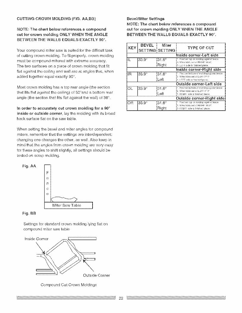
CUTTINGCROWNMOLDING(FIG. AA,BB)
NOTE: The chart below references s compoundcut for crown motding ONLY WHEN THE ANGLEBETWEEN THE WALLS EQUALS EXACTLY 90 °.
Your compound miter saw is suited for the difficult taskof cutting crown molding. To fit properly, crown molding
must be compound=mitered with extreme accuracy.The two surfaces on a piece of crown molding that fitfiat against the ceiling and wall are at angles that, whenadded together equal exactly 90°.
Most crown molding has a top rear angle (the section
that fits fiat against the ceiling) of 52°and a bottom rearangle (the section that fits fiat against the wall) of 38°.
tn order to accurately cut crown molding for s 90°inside or outside corner, lay the molding with its broadback surface fiat on the saw table.
Bevel/Miter Settings
NOTE: The chart below references s compoundcut for crown molding ONLY WHEN THE ANGLEBETWEEN THE WALLS EQUALS EXACTLY 90°.
KEY BEVELSETTING
33.9 °
IR 3&9 °
OL 3&9 °
OR J3&9°
Miter I,SETTING
R1.6 °ight
31.6 °Left
31.6 °Left
R1-6 °_ght
TYPE OF CUT
inside corner-Left side
L osition top of molding against fenceMiter tame set at RIGHT 31 6<
LEFT side is finished piece
hside corner-Right side
Position bottom of molding against fenceMiter tame set at LEFT 31 6°
3 LEFT side is finished piece
Outside corner-Left side
Position bottom of molding against fenceMiter table set at LEFT 31 6°
3 RIGHT side is firlished piece
Outside corner-Right side
Eli osition top of molding against fenceMiter table set at RIGHT 31 6'
RIGHT sk_e is finished piece
When setting the bevel and miter angles for compoundmiters, remember that the settings are interdependent;changing one changes the other, as well Also keep in
mind that the angles from crown molding are very easyfor these angles to shift slightly, al! settings should betested on scrap molding.
Fig. AA
Fig. BB
FIem
nl
clem
Miter Saw Table
Settings for standard crown molding lying fiat oncompound miter saw table
Inside Corner
Outside Corner
Compound Cut Crown Moldings
MAINTENANCE
IA DA"GERnNever put lubricants on the blade while it isspinning.
IAWARNINGnTo avoid fire or toxic reaction, never use gasoline,naphtha acetone, lacquer thinner or similar highlyvo!stile solvents to clean the miter saw.
electrical shock, unplug the power cord beforeworking on the saw.
IAwAR.I.GnFor your safety,thissaw isdouble-insulated.To
avoid electrical shock, fire or injury, use onlyparts identical to those identified in the parts list°Reassemble exactly as the original assembly toavoid electrical shock.
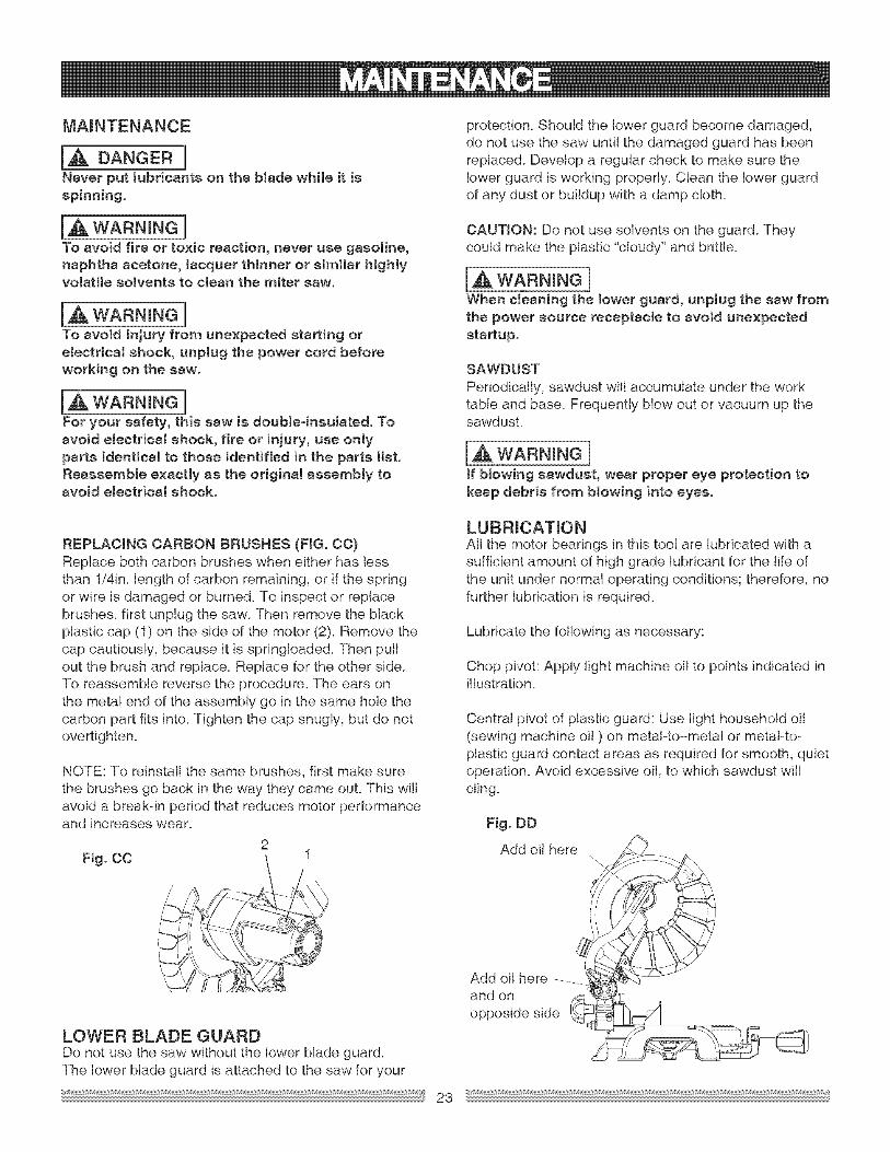
REPLACING CARBON BRUSHES (FIG. CO)Replace both carbon brushes when either has lessthan 1/4in. length of carbon remaining, or if the springor wire is damaged or burned. To inspect or replacebrushes, first unplug the saw. Then remove the blackplastic cap (1) on the side of the motor (2). Remove thecap cautiously, because it is springloaded. Then pullout the brush and replace. Replace for the other side.To reassemble reverse the procedure. The ears onthe metal end of the assembly go in the same hole thecarbon part fits into. Tighten the cap snugly, but do notovertighten.
NOTE: To reinsta!l the same brushes, first make surethe brushes go back in the way they came out. This wil!avoid s break-in period that reduces motor performanceand increases wear.
2Fig. CO 1
protection. Should the lower guard become damaged,do not use the saw until the damaged guard has beenreplaced. Develop s regular check to make sure thelower guard is working properly. Clean the lower guardof any dust or buildup with a damp cloth.
CAUTION: Do not use solvents on the guard. Theycould make the plastic "cloudy" and brittle.
WARNING]When ctesning the lower guard, unplug the saw fromthe power source receptacle to avoid unexpectedstartup.
SAWDUST
Periodically, sawdust will accumulate under the worktable and base. Frequently blow out or vacuum up thesawdusL
[,& WARNING]ff btowing sawdust, wear proper eye protection tokeep debris from blowing into eyes.
LUBRICATmONAtl the motor bearings in this tool are lubricated with asufficient amount of high grade lubricant for the life ofthe unit under normal operating conditions; therefore, nofurther lubrication is required.
Lubricate the following as necessary:
Chop pivot: Apply light machine off to points indicated inillustration.
Central pivot of plastic guard: Use light household oil
(sewing machine off ) on metal=to=metal or metal=to=plastic guard contact areas as required for smooth, quietoperation. Avoid excessive off, to which sawdust willcling.
Fig. DD
Add oil here
LOWER BLADE GUARDDo not use the saw without the lower blade guard.The lower blade guard is attached to the saw for your
4Add oilhere ....... I
and on _opposide side _
23
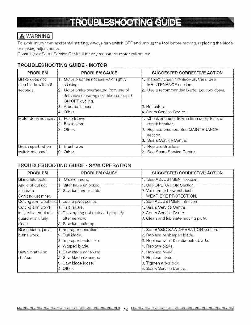
IA WARNINGnTo avoidinjuryfromaccidentalstarting,alwaysturnswitchOFF and unplugthetoolbeforemoving,replacingtheblade
or making adjustments_Consult your Sears Service Centre if for any reason the motor wi!! not run.
TROUBLESHOOTING GUIDE o MOTOR
PROBLEM
Brake does not
stop blade within 6seconds.
Motor does not start
PROBLEM CAUSE
1. Motor brushes not sealed or lightlysticking.
2. Motor brake overheated from use of
defective or wrong size blade or rapidON/OFF cycling.
Brush spark when 1. Brush worn.switch released. 2. Other.
TROUBLESHOOTING GUIDE o SAW OPERATION
PROBLEM PROBLEM CAUSE SUGGESTED CORRECTIVE ACTION
Blade hits table. 1. MisalignmenL 1. See ADJUSTMENT section.
Angle of cut not 1. Miter table unlocked. 1. See OPERATION Section.accurate. 2. Sawdust under table. 2. Vacuum or blow out dust,Can't adjust miter. WEAR EYE PROTECTION.Cutting arm wobbles. 1. Loose pivot points. 1. See ADJUSTMENT Section.
Cutting arm won't 1. Part failure. 1. Sears Service Centre.fully raise, or blade 2. Pivot spring not replaced properly 2. Sears Service Centre.
guard won't fully after service. 3. Clean and lubricate moving parts.close. 3. Sawdust build=up.
Saw vibrates or 1. Saw blade not round. 1. Replace blade.shakes. 2. Saw blade damaged. 2. Replace blade.
3. Saw blade loose. 3. Tighten arbor bolt.4. Other. 4. Sears Service Centre.
3. Retighten.4. Sears Service Centre.
1. Check and use15-Amp time delay fuse, orcircuit breaker.
2. Replace brushes. See MAINTENANCEsection.
3. Sears Service Centre.
1. Replace Brushes.2. See Sears Service Centre.
24
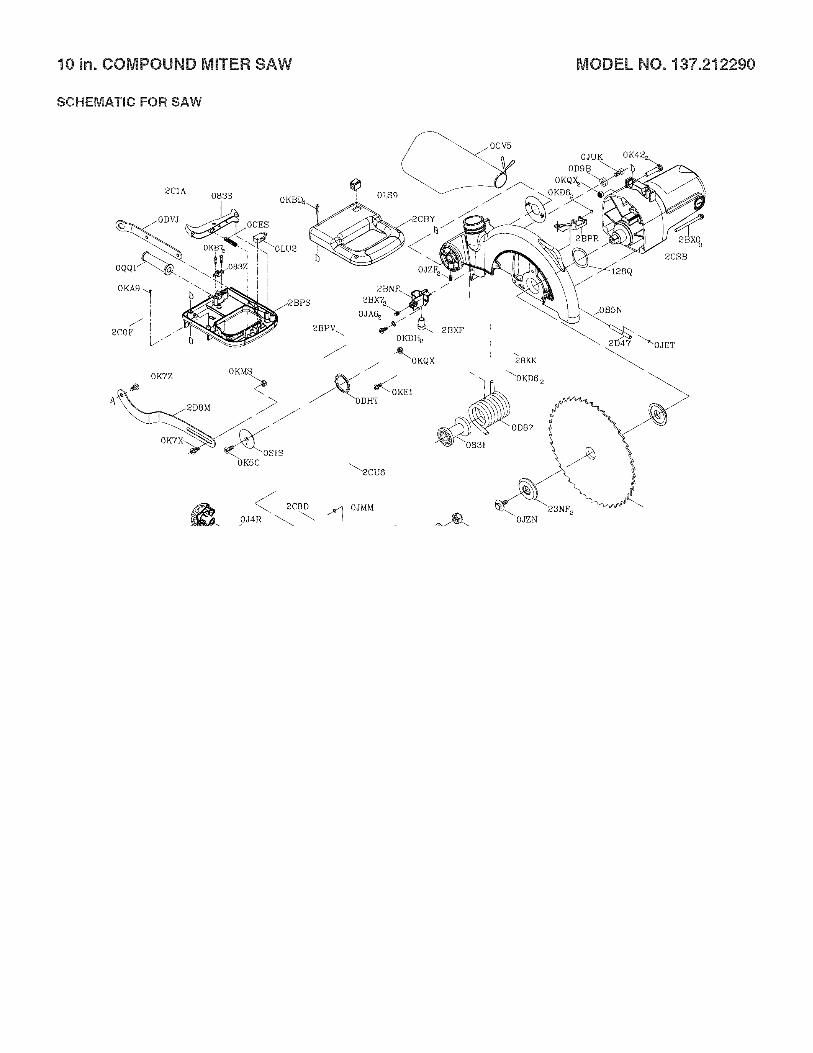
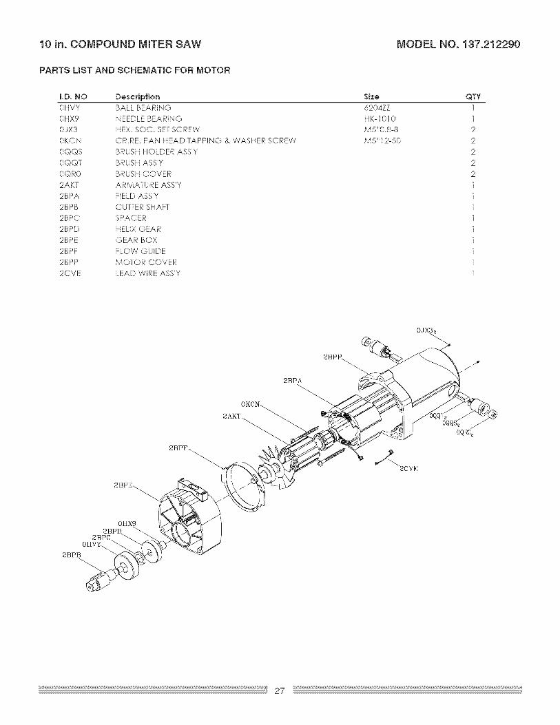
10 in. COMPOUND MITER SAW MODEL NO. 137.212290
IA WAR"I"GnWhen servicing use only CRAFTSMAN replacement parts. Use of any other parts many create a HAZARD or cause
product damage. Any attempt to repair or replace electrical parts on this Miter Saw may create a HAZARD unlessrepair is done by a qualified service technician. Repair service is available at your nearest Sears Service Centre.To purchase replacement parts, call 1°800°469°4663.