American Journal of Electrical Power and Energy Systems 2019; 8(2): 42-49 http://www.sciencepublishinggroup.com/j/epes doi: 10.11648/j.epes.20190802.11 ISSN: 2326-912X (Print); ISSN: 2326-9200 (Online) Optimal Location of Upfc to Improve Power System Voltage Stability Using Artificial Bee Colony Algorithm Bairu Vijay Kumar Department of Electrical and Electronics Engineering, Kakatiya Institute of Technology and Science, Warangal, India Email address: To cite this article: Bairu Vijay Kumar. Optimal Location of Upfc to Improve Power System Voltage Stability Using Artificial Bee Colony Algorithm. American Journal of Electrical Power and Energy Systems. Vol. 8, No. 2, 2019, pp. 42-49. doi: 10.11648/j.epes.20190802.11 Received: January 17, 2019; Accepted: March 7, 2019; Published: April 9, 2019 Abstract: In this paper a heuristic technique based optimal location of UPFC to improve the performance of power system is proposed. Here, the maximum power loss bus is identified as the most suitable location for fixing the UPFC. Generator outage affects the power flow constraints such as power loss, voltage, real and reactive power flow. Generator outage at different buses is introduced and the performance of the system is analyzed. The optimum location has been determined using the Artificial Bee Colony Algorithm (ABC) under this condition. By connecting UPFC at optimal location given by ABC algorithm, the power loss in the system is reduced and voltage profile is improved. Proposed work is implemented in the MATLAB and tested on IEEE 30 bus system. Initially the single generator outage is introduced at different buses in the system and afterwards double generator outage is introduced. In these conditions, the voltage profile and the power loss is analyzed at normal condition, outage condition and after connecting UPFC whose location given by proposed ABC algorithm. Performance of this algorithm is evaluated by comparing the results with those of different techniques. The comparison results demonstrate the superiority of the proposed approach and confirm its potential to solve the voltage stability problem. Keywords: UPFC, ABC Algorithm, Power Loss, Generator 1. Introduction The mount of electric power that can be transferred between two points through a transmission network is restricted by safety and stability constraints [1]. Around the world, Electric power systems have been forced to work more or less with their full capacities owing to the environmental and economic constraints in order to erect new generating plants and transmission lines [2-3]. Power flow in the lines should not be permitted to raise to a level where a random incident could cause the network fall down as a result of cascaded outages [4]. There have been many failures in the power system throughout the world due to voltage instability because of increasing system loads without sufficient transmission and/or generation enhancements [5]. When the voltages at the system buses are low, the losses will also be increased. For controlling the power transmission system, Flexible AC Transmission System (FACTS) is a stationary tool that is employed in order to mitigate the above problems [6]. FACTS devices are basically power electronic devices that have the capability to control various parameters of transmission lines, both in steady-state and in dynamic state [7]. Various kinds of FACTS devices offered for this specific purpose involves Static Var Compensator (SVC), Thyristor controlled series Capacitor (TCSC), Static Synchronous series compensator (SSSC), Static Synchronous Compensator (STATCOM), Unified Power Flow Controller (UPFC) and Interline Power Flow Controller (IPFC) [9]. UPFC was one of the FACTS device proposed by L. Gyugyiand it is a multiple-functional FACTS device with primary duty of power flow control. The secondary functions of the UPFC can be voltage control, transient stability improvement and power oscillation damping etc. [8, 10]. Novel opportunities for controlling power and improving the utilizable sizing of surviving transmission lines are released by the appearance of FACTS devices [11]. An optimal location of UPFC permits to control its power flows for a meshed network and as a result the system load ability can be raised [12]. However, a limited number of devices, beyond which this load ability cannot be improved, are observed [13]. Due to high capital investment, it is necessary
Transcript
American Journal of Electrical Power and Energy Systems 2019; 8(2): 42-49
http://www.sciencepublishinggroup.com/j/epes
doi: 10.11648/j.epes.20190802.11
ISSN: 2326-912X (Print); ISSN: 2326-9200 (Online)
Optimal Location of Upfc to Improve Power System Voltage Stability Using Artificial Bee Colony Algorithm
Bairu Vijay Kumar
Department of Electrical and Electronics Engineering, Kakatiya Institute of Technology and Science, Warangal, India
Email address:
To cite this article: Bairu Vijay Kumar. Optimal Location of Upfc to Improve Power System Voltage Stability Using Artificial Bee Colony Algorithm. American
Journal of Electrical Power and Energy Systems. Vol. 8, No. 2, 2019, pp. 42-49. doi: 10.11648/j.epes.20190802.11
Received: January 17, 2019; Accepted: March 7, 2019; Published: April 9, 2019
Abstract: In this paper a heuristic technique based optimal location of UPFC to improve the performance of power system is
proposed. Here, the maximum power loss bus is identified as the most suitable location for fixing the UPFC. Generator outage
affects the power flow constraints such as power loss, voltage, real and reactive power flow. Generator outage at different
buses is introduced and the performance of the system is analyzed. The optimum location has been determined using the
Artificial Bee Colony Algorithm (ABC) under this condition. By connecting UPFC at optimal location given by ABC
algorithm, the power loss in the system is reduced and voltage profile is improved. Proposed work is implemented in the
MATLAB and tested on IEEE 30 bus system. Initially the single generator outage is introduced at different buses in the system
and afterwards double generator outage is introduced. In these conditions, the voltage profile and the power loss is analyzed at
normal condition, outage condition and after connecting UPFC whose location given by proposed ABC algorithm.
Performance of this algorithm is evaluated by comparing the results with those of different techniques. The comparison results
demonstrate the superiority of the proposed approach and confirm its potential to solve the voltage stability problem.
Keywords: UPFC, ABC Algorithm, Power Loss, Generator
1. Introduction
The mount of electric power that can be transferred
between two points through a transmission network is
restricted by safety and stability constraints [1]. Around the
world, Electric power systems have been forced to work
more or less with their full capacities owing to the
environmental and economic constraints in order to erect new
generating plants and transmission lines [2-3]. Power flow in
the lines should not be permitted to raise to a level where a
random incident could cause the network fall down as a
result of cascaded outages [4]. There have been many failures
in the power system throughout the world due to voltage
instability because of increasing system loads without
Step 2: Generate the random number of population input
voltage and the power loss.
Step 3: The employ bee phase, which evaluates the fitness
of the population; the required fitness function is given in the
following equation (9).
1
cos( )
N
i j ij ij i j
n
Max V V Y α δ δ=
Φ = − −
∑ (9)
Step 4: Set the iteration count as 1, i.e., iteration I=1.
Step 5: Repeat
Step 6: The onlooker bee attains the elite fitness function
of the bus system and improve the velocity of the populations
using the following equation (10).
, , , , ,( )i j i j i j i j k jV x x x= + Φ − (10)
Where, k is the solution the neighborhood of i , Ψ is a
random number in the range [-1, 1], (1, 2,3 )k n= … and
(1, 2,3 )j n= … are the randomly chosen index and ,i jV is
the neighborhood solution of iX .
Step 7: Apply the selection process to find the better
fitness of the new solutions and determine the probability.
American Journal of Electrical Power and Energy Systems 2019; 8(2): 42-49 46
1
n
i
probability
=
Φ=Φ∑ (11)
Step 8: If better solutions are not achieved, abandon the
solutions and produce the random number of scout bee
solution using the following equation (12).
maxmin min[0,1]( )j jj j
ix x rand x x= + − (12)
Step 9: Memorize the best solution achieved so far.
Step 10: To check the iteration range, if the iteration not
achieves the maximum range increase the iteration count
I=I+1 or else terminate the process.
Once the above process is finished, the system is ready to
produce the maximum power loss bus for the specified generator
bus outage condition. Once the UPFC is connected at optimum
location given by the algorithm, power loss is minimized,
voltage profile is improved thus power system stability
improved. The proposed algorithm is implemented in the
MATLAB platform and its performance is checked with various
operating conditions. It is given in the following section 4.
4. Results and Discussions
The proposed algorithm is implemented in the MATLAB
platform. The numerical results of the proposed method is
presented and discussed in this section. The obtained results
are compared with various operating environments. Here, the
ABC algorithm is applied to the IEEE standard bench mark
system like IEEE 30 bus system.
Figure 2. Structure of the IEEE 30 bus system.
Validation of IEEE 30 bus system
The Structure of the IEEE 30 bus system is shown in
Figure 2. IEEE-30 bus benchmark system consists of six
generator buses, 21 load buses and 42 transmission lines.
Initially, the system base case load flow analysis is done by
the standard Newton-Raphson (N-R) algorithm. Here, the
IEEE 30 bus system standard data isused. Afterwards, the
generator outages (single and double) are introduced and the
corresponding stability is analyzed. Due to the generator
outages the system loses the stability, which can be identified
by the load flow analysis of the system after the generator
outage. Stability conditions can be restored by connecting
optimum sizing of UPFC placed at optimal location, which
can be determined by the proposed ABC algorithm.
4.1. Single Generator Outage
In this case at a time one generator is given outage and
corresponding stability is analyzed.
Figure 3. Voltage profile for 2nd bus generator outage condition with ABC
algorithm.
Figure 4. Voltage profile for 6th bus generator outage conditionwith ABC
algorithm.
The voltage profile variation for IEEE-30 bus system at
single generator outage is shown in Figure 3. Here, second
bus generator is given outage. The voltage profile is shown
for normal condition, during the generator outage and after
connecting the UPFC whose location is determined using
ABC algorithm. The voltage profile variations of the same
system for sixth bus generator outages is shown in Figure 4.
47 Bairu Vijay Kumar: Optimal Location of Upfc to Improve Power System Voltage Stability Using Artificial Bee Colony Algorithm
From the voltage profile analysis, it is found that the voltage
profile is disturbed for the generator outage condition. But
the voltage profile is restored to the normal condition after
connecting UPFC.
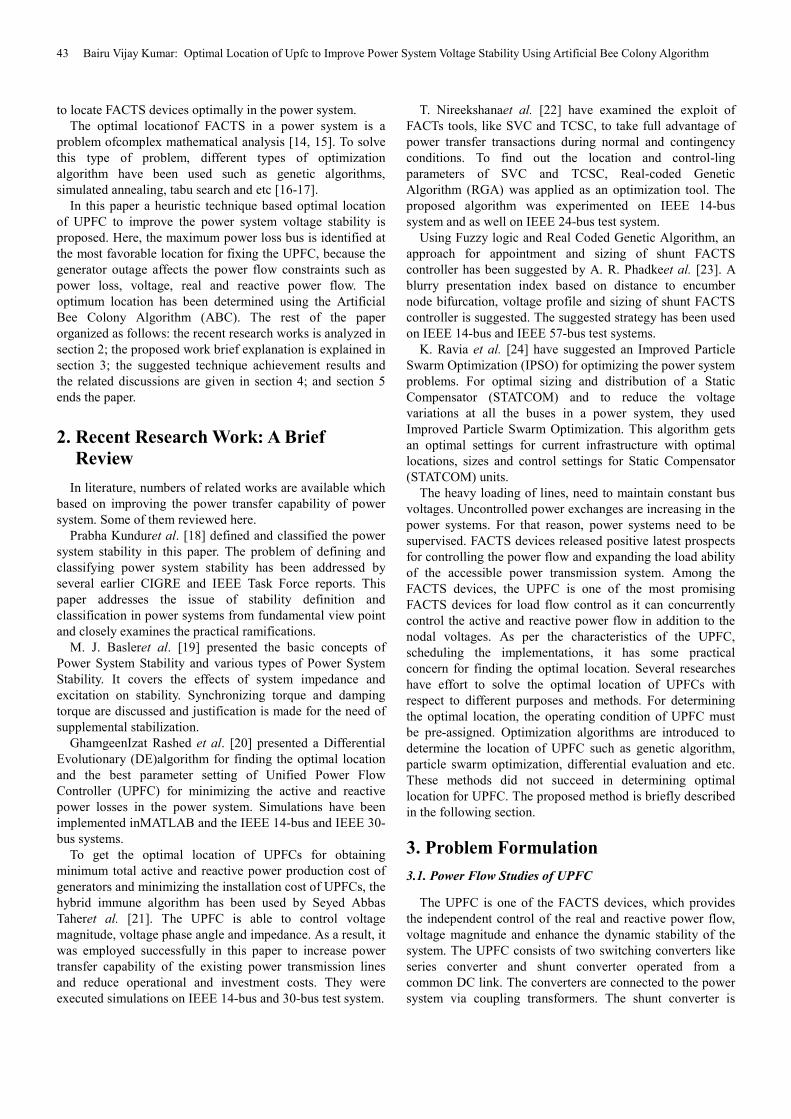
Table 1. Power loss comparison for single generator outage condition using ABC algorithm.
Outage of
generatorat bus no.
Power loss in MW
During normal condition During generator outage condition After connecting UPFC whose
location is given by ABC algorithm
2 10.809 12.768 9.858
Table 1 gives power loss comparison for different
conditions i.e. Power loss at normal condition, generator
outage condition and after connecting the UPFC at optimal
location which is determined using ABC algorithms. Here, it
is observed that the power loss is increased to 12.768 MW
during single generator outage condition and the power loss
is reduced to 9.858MWafter connecting UPFC whose
location is determined by proposed ABC algorithm. This
shows effectiveness of proposed algorithm.
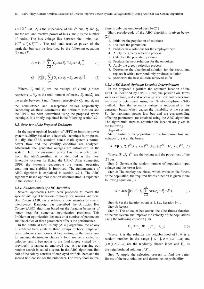
4.2. Double Generator Outage Condition
In this case at a time two generators are given outages and
corresponding stability is analyzed.
Figure 5. Voltage profile for generators outage at buses 2 and 6 with ABC
algorithm.
Figure 6. Voltage profile for generators outage at buses 2 and 13 with ABC
algorithm.
The voltage profile variation for IEEE-30 bus system at
double generator outage is shown in Figure 5. Here
generators at buses 2 & 6 are given outage. The voltage
profile is shown for normal condition, during the double
generator outage and after connecting the UPFC whose
location is determined using ABC algorithm. Figure 6 shows
voltage profile variations for double generator outage at
buses 2 & 13. From the voltage profile analysis, it is found
that the voltage profile at the buses is disturbed for the
generator outage, but the voltage profile is restored to normal
condition after connecting the UPFC. Table 2 gives power
loss comparison under double generator outages for different
conditions i.e. Power loss at normal condition, Power loss at
double generator outage condition, Power loss after
connecting the UPFC at optimal location which is determined
using ABC algorithm. Here, it can be observed that power
loss is increased to 14.005MW during double generator
outage and it is reduced to 9.862 MW after connecting UPFC
whose location and sizing are given by proposed ABC
algorithm. Figures 3 to 6 and Tables 1 to 2 clearly show the
effectiveness and superiority of the proposed ABC algorithm
to restore power system stability under generator outage
conditions.
Table 2. Power loss comparison for double generator outage using Hybrid
ABC-GSA algorithm.
Outage of generators
at bus nos.
Power loss in MW
During normal
condition
During generator
outage condition ABC
6 13 10.809 14.005 9.862
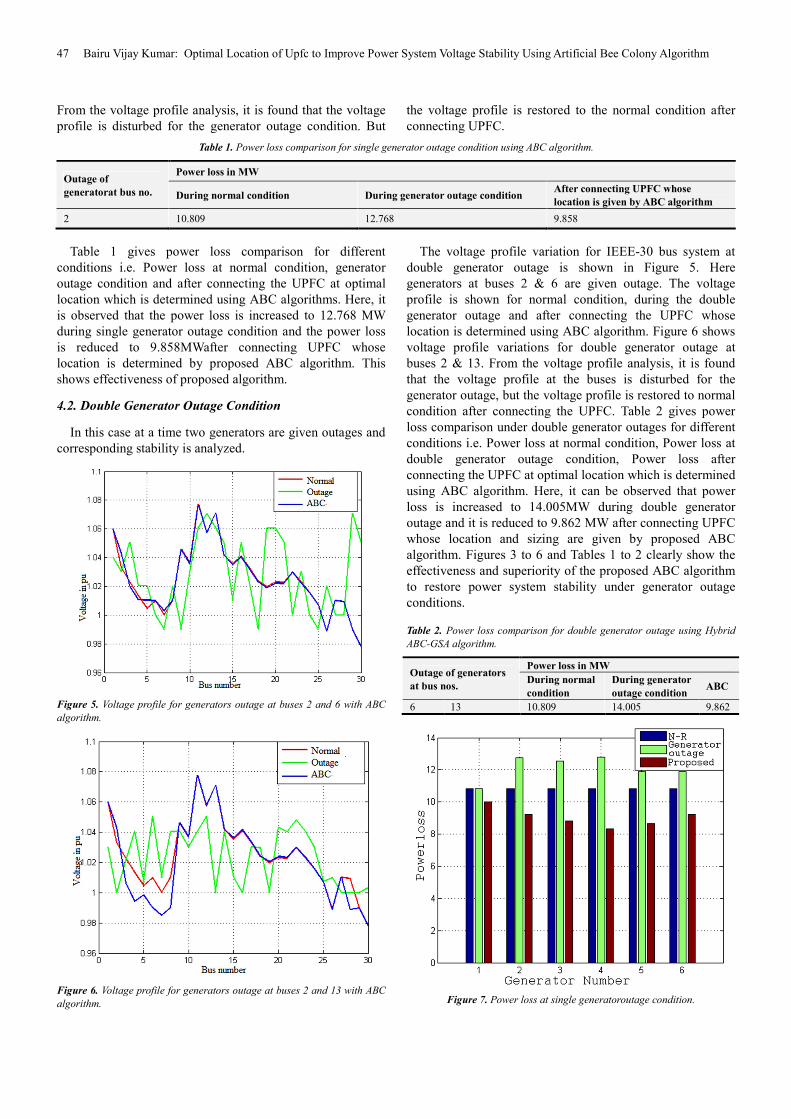
Figure 7. Power loss at single generatoroutage condition.
American Journal of Electrical Power and Energy Systems 2019; 8(2): 42-49 48
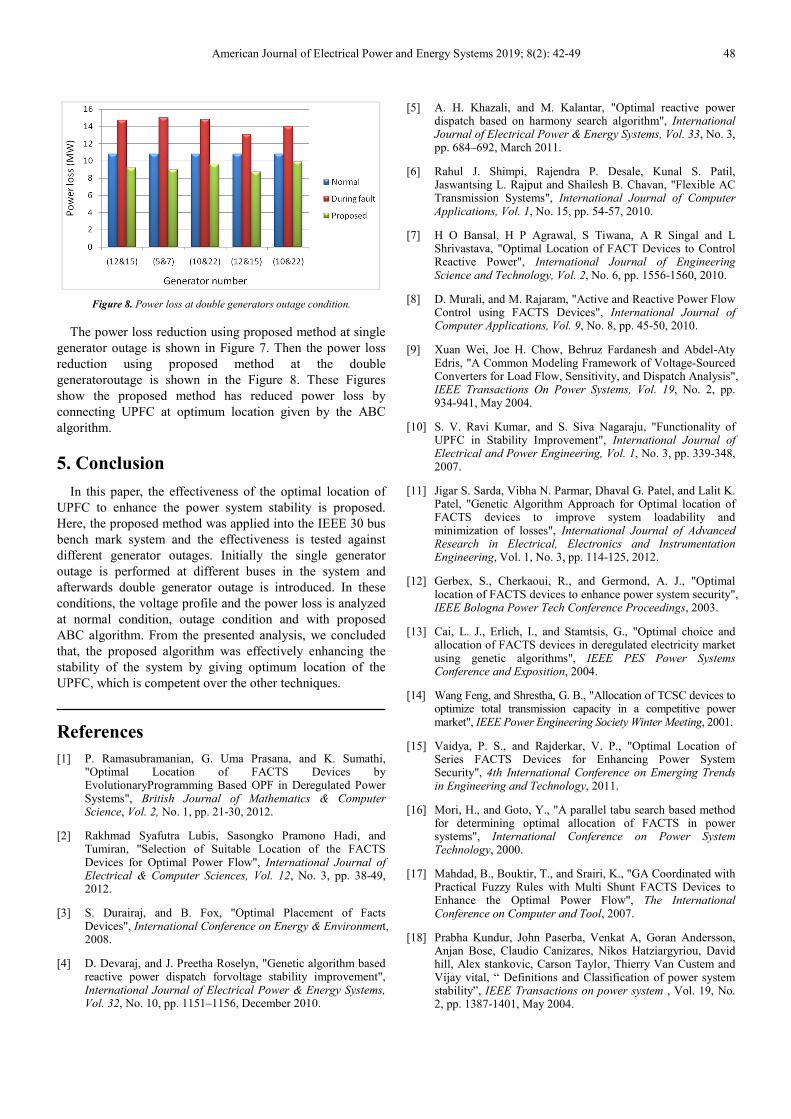
Figure 8. Power loss at double generators outage condition.
The power loss reduction using proposed method at single
generator outage is shown in Figure 7. Then the power loss
reduction using proposed method at the double
generatoroutage is shown in the Figure 8. These Figures
show the proposed method has reduced power loss by
connecting UPFC at optimum location given by the ABC
algorithm.
5. Conclusion
In this paper, the effectiveness of the optimal location of
UPFC to enhance the power system stability is proposed.
Here, the proposed method was applied into the IEEE 30 bus
bench mark system and the effectiveness is tested against
different generator outages. Initially the single generator
outage is performed at different buses in the system and
afterwards double generator outage is introduced. In these
conditions, the voltage profile and the power loss is analyzed
at normal condition, outage condition and with proposed
ABC algorithm. From the presented analysis, we concluded
that, the proposed algorithm was effectively enhancing the
stability of the system by giving optimum location of the
UPFC, which is competent over the other techniques.
References
[1] P. Ramasubramanian, G. Uma Prasana, and K. Sumathi, "Optimal Location of FACTS Devices by EvolutionaryProgramming Based OPF in Deregulated Power Systems", British Journal of Mathematics & Computer Science, Vol. 2, No. 1, pp. 21-30, 2012.
[2] Rakhmad Syafutra Lubis, Sasongko Pramono Hadi, and Tumiran, "Selection of Suitable Location of the FACTS Devices for Optimal Power Flow", International Journal of Electrical & Computer Sciences, Vol. 12, No. 3, pp. 38-49, 2012.
[3] S. Durairaj, and B. Fox, "Optimal Placement of Facts Devices", International Conference on Energy & Environment, 2008.
[4] D. Devaraj, and J. Preetha Roselyn, "Genetic algorithm based reactive power dispatch forvoltage stability improvement", International Journal of Electrical Power & Energy Systems, Vol. 32, No. 10, pp. 1151–1156, December 2010.
[5] A. H. Khazali, and M. Kalantar, "Optimal reactive power dispatch based on harmony search algorithm", International Journal of Electrical Power & Energy Systems, Vol. 33, No. 3, pp. 684–692, March 2011.
[6] Rahul J. Shimpi, Rajendra P. Desale, Kunal S. Patil, Jaswantsing L. Rajput and Shailesh B. Chavan, "Flexible AC Transmission Systems", International Journal of Computer Applications, Vol. 1, No. 15, pp. 54-57, 2010.
[7] H O Bansal, H P Agrawal, S Tiwana, A R Singal and L Shrivastava, "Optimal Location of FACT Devices to Control Reactive Power", International Journal of Engineering Science and Technology, Vol. 2, No. 6, pp. 1556-1560, 2010.
[8] D. Murali, and M. Rajaram, "Active and Reactive Power Flow Control using FACTS Devices", International Journal of Computer Applications, Vol. 9, No. 8, pp. 45-50, 2010.
[9] Xuan Wei, Joe H. Chow, Behruz Fardanesh and Abdel-Aty Edris, "A Common Modeling Framework of Voltage-Sourced Converters for Load Flow, Sensitivity, and Dispatch Analysis", IEEE Transactions On Power Systems, Vol. 19, No. 2, pp. 934-941, May 2004.
[10] S. V. Ravi Kumar, and S. Siva Nagaraju, "Functionality of UPFC in Stability Improvement", International Journal of Electrical and Power Engineering, Vol. 1, No. 3, pp. 339-348, 2007.
[11] Jigar S. Sarda, Vibha N. Parmar, Dhaval G. Patel, and Lalit K. Patel, "Genetic Algorithm Approach for Optimal location of FACTS devices to improve system loadability and minimization of losses", International Journal of Advanced Research in Electrical, Electronics and Instrumentation Engineering, Vol. 1, No. 3, pp. 114-125, 2012.
[12] Gerbex, S., Cherkaoui, R., and Germond, A. J., "Optimal location of FACTS devices to enhance power system security", IEEE Bologna Power Tech Conference Proceedings, 2003.
[13] Cai, L. J., Erlich, I., and Stamtsis, G., "Optimal choice and allocation of FACTS devices in deregulated electricity market using genetic algorithms", IEEE PES Power Systems Conference and Exposition, 2004.
[14] Wang Feng, and Shrestha, G. B., "Allocation of TCSC devices to optimize total transmission capacity in a competitive power market", IEEE Power Engineering Society Winter Meeting, 2001.
[15] Vaidya, P. S., and Rajderkar, V. P., "Optimal Location of Series FACTS Devices for Enhancing Power System Security", 4th International Conference on Emerging Trends in Engineering and Technology, 2011.
[16] Mori, H., and Goto, Y., "A parallel tabu search based method for determining optimal allocation of FACTS in power systems", International Conference on Power System Technology, 2000.
[17] Mahdad, B., Bouktir, T., and Srairi, K., "GA Coordinated with Practical Fuzzy Rules with Multi Shunt FACTS Devices to Enhance the Optimal Power Flow", The International Conference on Computer and Tool, 2007.
[18] Prabha Kundur, John Paserba, Venkat A, Goran Andersson, Anjan Bose, Claudio Canizares, Nikos Hatziargyriou, David hill, Alex stankovic, Carson Taylor, Thierry Van Custem and Vijay vital, “ Definitions and Classification of power system stability”, IEEE Transactions on power system , Vol. 19, No. 2, pp. 1387-1401, May 2004.
49 Bairu Vijay Kumar: Optimal Location of Upfc to Improve Power System Voltage Stability Using Artificial Bee Colony Algorithm
[19] Basler, M. J. Schaefer, R. C. Understanding Power System Stability. IEEE Transactions on Industry Applications. March/April 2008; 44(2): 463-474.
[20] Ghamgeen Izat Rashed, Yuanzhang Sun, Khalid A. Rashed, and H. I. Shaheen, “Optimal Location of Unified Power Flow Controller by Differential Evolution Algorithm Considering Transmission Loss Reduction”, IEEE POWECON 2012, pp1-6.
[21] Seyed Abbas Taher, and Muhammad KarimAmooshahi, "New approach for optimal UPFC placement using hybrid immunealgorithm in electric power systems", Electrical Power and Energy Systems, Vol. 43, pp. 899-909, 2012.
[22] T. Nireekshana, G. Kesava Rao, and S. Siva Naga Raju, "Enhancement of ATC with FACTS devices using Real-code Genetic Algorithm", Electrical Power and Energy Systems, Vol. 43, pp. 1276–1284, 2012.
[23] A. R. Phadke, and Manoj Fozdar, K. R. Niazi, "A new multi-objective fuzzy-GA formulation for optimal placement and sizing of shunt FACTS controller", International Journal of Electrical Power & Energy Systems, Vol. 40, No. 1, pp. 46–53, September 2012.
[24] K. Ravia and M. Rajaram, "Optimal location of FACTS devices using Improved Particle Swarm Optimization", International Journal of Electrical Power & Energy Systems, Vol. 49, pp. 333–338, July 2013.
[25] AbdelazizLaifa and Mohamed Boudour, "Optimal Placement and Parameter Settings of Unified Power Flow Controller
Device using a Perturbed Particle Swarm Optimization", IEEE International Energy Conference and Exhibition, pp. 205-210, 2010.
[26] D. Karboga and B. Basturk, “A Powerful and efficient algorithm for numerical function optimization: Artificial bee colony (ABC) algorithm”, Applied Soft Computing, Vol. 8, No. 1, pp. 687-697, 2008.
[27] D. Karboga and Bahriye Akay, “A comparative study of Artificial Bee Colonyalgorithm”, Applied Mathematics and Computation, Vol. 214, No. 1, pp. 108-132, 2009.
Biography
Bairu Vijay Kumar was born in Warangal,
India, in April 1978. He received the B. Tech
degree in Electrical & Electronics
Engineering, M. Tech degree in Power
Systems Engineering and Ph.D in electrical
engineering from National Institute of
Technology, Warangal, India, in 2002, 2008
and 2015 respectively. He is currently working as Asst. professor
in EEED of Kakatiya institute of Technology &Science, Warangal,
India. He published papers in various Sci indexed and other peer
reviewed journals. His Current research interest includes
Enhancement of Power System Stability using FACTS devices and


![Deciding optimal location for placing FACTS devices [UPFC, IPQC, DPFC] using Bang-Bang control technique](https://static.documents.pub/doc/80x56/577cc8811a28aba711a300aa/deciding-optimal-location-for-placing-facts-devices-upfc-ipqc-dpfc-using.jpg)


